1
TECHNICAL DATASHEET #TDAX021500
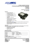
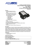
HYDRAULIC FAN CONTROLLER
Application Platform
3 Temperature Sensors
4 Digital Command Interfaces
1 PWM Input and 1 Analog Input
1 Proportional or ON/OFF Current Output
RS232 Port
P/N: AX021500
Description:
The hydraulic fan controller provides precise, repeatable control of 1
proportional or on/off solenoid valve to adjust the speed of a hydraulic fan.
Fan speed is inversely proportional to the current through the valve. Valve
current control is based on up to three 2-wire temperature sensor inputs.
An additional analog input can be used for an override input or other
function. A +5V reference powers the override potentiometer. One digital
input can be used as manual control input to allow the fan speed in this
mode to be set by the Override Potentiometer or analog input. A PWM
input is available for interface to an engine ECM (electronic control module)
or PWM temperature sensor. Three digital inputs allow for speed advance,
speed retard and fan reverse functions (or other functions). The robust
design accepts 9…32V power supply input and is packaged in an IP67
rated housing with 24-pin connectors. The controller is designed for remote mounting. RS-232 port interfaces to
PC with Tera Term freeware for user configuration and diagnostics. Other hydraulic control applications beyond
fan controls can be accommodated with this hardware and application-specific software.
Applications include: Hydraulic Fan Drives; and Industrial and off-highway (mobile) applications for control of
hydraulic valves.
Features:
•
•
•
•
•
•
•
•
•
•
•
•
•
Independent output drives 1 solenoid valve (on/off or proportional)
Up to 3 analog temperature sensor inputs with +5V reference power
One PWM input interfaces to an ECM or PWM temperature sensor
Three active low digital inputs (interface to switches, fan reverse and other fan control commands, etc.)
One digital input can be used as manual control input to allow the fan speed in this mode to be set by
the Override Potentiometer or analog input.
Universal analog input (0-5V, 0-10V, 4-20 mA, 0-20 mA)
+5V reference can power a potentiometer
Interfaces to a 9…32VDC power supply with reverse polarity protection
Thermal overload and overvoltage protection provided
User configurability is provided within factory preset ranges based on the application
Rugged IP67 rated packaging with plug-in connections
Operational from -40 to 85°C (-40 to 185°F)
RS232 interface to PC or laptop for user configuration and diagnostics
Ordering Part Numbers:
Controller: AX021500
(For application-specific s/w please contact Axiomatic for a part number.)
Accessories:
AX070000 Mating Plug Kit with DB-9
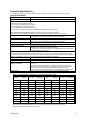
Technical Specifications:
The specifications represent a particular hardware platform. (Application-specific s/w will be provided on request).
Input Specifications
Power Supply Input - Nominal
12 or 24VDC nominal; 9…32 VDC power supply range
Reverse Polarity Protection
Provided
Analog Inputs
Delphi sensors are accepted (see Table 1).
p/n 12146897 coolant/fluid temperature sensor
p/n 12110446 sealed air temperature sensor
p/n 121295956 exposed air temperature sensor
The controller also accepts Honeywell NTC thermistors p/n 50006023-001 (see Table 2).
The user may also select different sensors. Sensors with a linear response are preferred.
Upon ordering, provide details of the selected sensors’ specifications for factory programming the controller.
Temperature Sensor Inputs
3 temperature sensor inputs
User specifies sensor, range of temperature control and setpoints
Sensors’ Ground
Common ground connection provided.
Analog Input 1
0-5V, 0-10 VDC, 4-20 mA, 0-20 mA
Option: 0.25 – 4.75 V potentiometer (5K to 10K) (software feature)
Analog Ground
Analog ground provided
PWM Input
PWM Temperature Input
PWM pulse – normal/reverse polarity up to 3 kHz
Adjustable from 0-100% Duty Cycle (5-95% default)
For example, the controller could interface to a PWM signal from an engine ECM or
an external PWM temperature sensor.
Digital Inputs
The controller accepts switched inputs or other digital inputs. For example, in a hydraulic fan drive application, digital
inputs can be specified to perform these functions: fan direction CW/CCW, climate control ON/OFF, reduce flow (speed
retard); speed advance. Fan reverse has an additional programmed parameter of hold time.
Digital Input 1
Active Low
Digital Input 2
Active Low
Digital Input 3
Active Low
Digital Input 4
Manual Control (MC)
MANUAL CONTROL
Active Low
The manual control input switches the controller into the manual control mode.
The fan speed in this mode is set by the Override Potentiometer or analog input.
If MC is active, the fan speed is determined ONLY by the Override Input.
If MC is passive, the fan speed is determined by the temperature and PWM inputs.
Digital Ground
Common digital ground connection provided (shared as PWM input GND)
Table 1: Delphi Sensor Temperature vs. Output (Resistance) Table
Temp
[Deg C]
Resistance
[ohms]
Res
[+/- %]
Ref Acc
[+/- Deg C]
Temp [Deg
C]
Resistance
[ohms]
Res
[+/- %]
Ref Acc
[+/- Deg C]
20
3511
2.64
0.60
75
395
2.07
0.60
25
2795
2.50
0.60
80
334
2.04
0.60
30
2240
2.45
0.60
85
283
2.00
0.60
35
1806
2.40
0.60
90
241.8
2.10
0.70
40
1465
2.36
0.60
95
207.1
2.21
0.70
45
1195
2.31
0.60
100
178.0
2.31
0.80
50
980
2.27
0.60
105
153.6
2.42
0.80
55
809
2.23
0.60
110
133.1
2.52
0.90
60
671
2.19
0.60
115
115.7
2.61
0.90
65
559
2.15
0.60
120
100.9
2.68
1.00
70
469
2.11
0.60
Note: The table only applies between 20˚C to 120˚C. Temperatures below this range are set to 20˚C,
and temperatures above this range are set to 120˚C.
TDAX021500
2
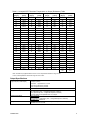
Table 2: Honeywell NTC Thermistor Temperature vs. Output (Resistance) Table
Temp
[Deg C]
Resistance
[ohms]
Temp
[Deg C]
Resistance
[ohms]
Temp
[Deg C]
Resistance
[ohms]
Temp
[Deg C]
Resistance
[ohms]
20
1249.5
45
436.6
70
175.2
95
78.8
21
1194.5
46
420.0
71
169.3
96
76.5
22
1142.1
47
404.0
72
163.7
97
74.3
23
1092.3
48
388.6
73
158.3
98
72.1
24
1045.0
49
374.0
74
153.1
99
70.0
25
1000.0
50
360.0
75
148.1
100
68.0
26
957.2
51
346.6
76
143.3
101
66.0
27
916.4
52
333.8
77
138.6
102
64.2
28
877.6
53
321.5
78
134.1
103
62.3
29
840.7
54
309.7
79
129.8
104
60.6
30
805.5
55
298.4
80
125.7
105
58.9
31
772.0
56
287.6
81
121.7
106
57.2
32
740.0
57
277.3
82
117.9
107
55.6
33
709.6
58
267.3
83
114.2
108
54.1
34
680.6
59
257.8
84
110.6
109
52.6
35
652.8
60
248.7
85
107.2
110
51.2
36
626.5
61
239.9
86
103.8
111
49.8
37
601.3
62
231.5
87
100.6
112
48.4
38
577.2
63
223.4
88
97.6
113
47.1
39
554.3
64
215.7
89
94.6
114
45.8
40
532.3
65
208.2
90
91.7
115
44.6
41
511.4
66
201.1
91
89.0
116
43.4
42
491.4
67
194.2
92
86.3
117
42.3
43
472.3
68
187.6
93
83.7
118
41.1
44
545.0
69
181.3
94
81.2
119
40.1
120
39.0
Note: The table only applies between 20˚C to 120˚C. Temperatures below this range are set
to 20˚C, and temperatures above this range are set to 120˚C.
Output Specifications
Maximum Current Output
(High frequency PWM output)
Reference Voltage
Output Current Adjustments
Superimposed Dither
Ramp Rate
TDAX021500
High side driver
1 output (up to 2A)
Solenoid A: 1 proportional or 1 on/off
Overcurrent protection is provided
Short circuit protection is provided.
+5V, 50 mA
I-max. (specified by user – configurable setpoint in software)
I-set (specified by user – configurable setpoint in software)
I-min. (specified by user – configurable setpoint in software)
All current settings are adjustable from 0 to 2 Amps.
Dither Amplitude:
10% I-max. (fixed)
Dither Frequency: (specified by user – configurable setpoint in software)
Adjustable from 700-350 Hz
Ramps to I-set: (specified by user – configurable setpoint in software)
Adjustable from 0-5 seconds.
3
Configurable Parameters
The following table illustrates typical fan control software available on request.
Alternatively, application-specific software can be provided.
Description
Default
Range
(Specified when order)
(Specified when order)
NTC
NTC
NTC
TBA
TBA
TBA
TBA
TBA
TBA
60
{NTC, PTC_RTD,
Delphi, Not _Active}
Enumerator
Temp. Sensor 1 Low
Temp. Sensor 1 High
Temp. Sensor 2 Low
Temp. Sensor 2 High
Temp. Sensor 3 Low
Temp. Sensor 3 High
Analog Input Filter Frequency
Al1_type
Al2_type
Al3_type
AI1_low
AI1_high
AI2_low
AI2_high
AI3_low
AI3_high
Al_ff
20-120
20-120
20-120
20-120
20-120
20-120
{50, 60}
ºC
ºC
ºC
ºC
ºC
ºC
PWM Input Low
PWM Input High
PWM Input Type
PWM_low
PWM_hi
PWM_type
5
95
Normal
Input Priority
Al_pri
No_Priority
% Speed Advance
% Speed Retard
Invert Output Current
(Fan Reverse)
I-set Ramp Time
Minimum Current
Setpoint Current
Maximum Output Current
Fan Reverse Hold Time
RPM_adv
RPM_ret
I_inv
I_ramp
I_min
I_set
I1_max
t_rev
Temp. Sensor Type
Variable Name
Unit
Enumerator,
Values are in
Hz
TBA
TBA
TBA
0-100
0-100
{Normal, Reversed,
Not_Active}
{TS1, TS2, TS3,
PWMI, No_Priority}
0-100
0-100
T/F
% D.C.
% D.C.
Enumerator
%
%
-
TBA
TBA
TBA
TBA
TBA
0-5
0-2000
0-2000
0-2000
0-20
sec
mA
mA
mA
sec
Enumerator
General Specifications
Microprocessor
Control Logic
Interface
Electrical Connections
Packaging and Dimensions
Operating Conditions
Vibration
Protection
Weight
Mounting
TDAX021500
MC56F8322
Application – specific software provided
The controller can be factory programmed with a range of temperatures (minimum
and maximum temperature setpoints) or a single temperature setpoint.
The priority of the digital inputs is factory programmed.
RS-232 on-board connection is available for setpoint configuration,
software upgrade and diagnostics.
RS232 serial communication interfaces to a serial port (i.e. COM1) on a PC
(115200 Baud Rate, N81, Xon/Xoff Flow Control)
TM
Tera Term or Microsoft HyperTerminal or an equivalent data terminal
24 pin
Deutsch DTM series 24 pin receptacle (DTM13-12PA-12PB-R008)
Mating plug: Deutsch DTM06-12SA and DTM06-12SB
with 2 wedgelocks (WM12S) and 24 contacts (0462-201-20141).
20 AWG wire is recommended for use with contacts 0462-201-20141.
Mating plugs are provided with prototypes only.
Use dielectric grease on the pins when installing the controller.
High Temperature Nylon housing
Deutsch IPD PCB Enclosure (EEC-325X4B)
4.62 x 5.24 x 1.43 inches 117.42 x 133.09 x 36.36 mm
(W x L x H excluding mating plug)
OEM specific packaging and connection styles are available.
-40 to 85°C (-40 to 185°F)
Vibration compliance is suitable for mobile equipment applications.
IP67; Unit is conformally coated within the housing. Plugs carry an IP69 rating.
Contact Axiomatic.
Contact Axiomatic.
4
Connections (Typical):
Refer to installation instructions for a specific part number for actual pin out.
Grey Connector
Pin #
1
2
3
4
5
6
7
8
9
10
11
12
Function
+5V Reference (Protected)
Analog Input (Potentiometer)
Analog GND or RS-232 GND (DB-9 Female, pin 5)
Solenoid ANot Used
Battery Battery +
Not Used
Solenoid A+
RS-232 Receive (DB-9 Female, pin 3)
RS-232 Transmit (DB-9 Female, pin 2)
Not Used
TDAX021500
Black Connector
Pin #
1
2
3
4
5
6
7
8
9
10
11
12
Function
Temperature Sensor 1
Temperature Sensor 2
Temperature Sensor 3
Temperature Sensors’ GND
Digital GND or RS-232 GND (DB-9 Female, pin 5)
PWM Input
Digital Input 1
Digital Input 2
Digital Input 3
Digital Input 4 (Manual Mode)
Not Used
Not Used
5
RS-232 communications:
For further details refer to the user manual for the specific part number.
Using a PC and Tera term freeware, the user can select between displaying system parameters,
changing system parameters, setting the default values, loading new software and showing the
internal state of the controller (diagnostics).
NB. Tera term is freeware and is downloadable from
http://hp.vector.co.jp/authors/VA002416/teraterm.html.
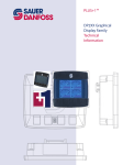
1. Setting Up PC Communications to the Controller
•
•
•
•
Connect an RS-232 to DB-9 cable adaptor to the controller and a PC.
Use a stable power supply. With the power supply OFF, connect the controller Power- to
the power supply Ground, and the Power+ to the power supply +.
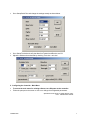
Open Tera Term Pro, and set it up as shown below.
(Free downloadable from http://hp.vector.co.jp/authors/VA002416/teraterm.html)
Select Serial with the appropriate COM port.
TDAX021500
6
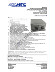
•
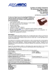
Go to Setup/Serial Port and change the settings exactly as shown below.
•
•
Go to Setup/Terminal and verify that New-line Transmit and Receive are CR.
Adjust the window size as desired by checking ‘Term size = win size’.
2. Configuring the Controller - Main Menu
•
•
To access the main menu for existing software, turn ON power to the controller.
Follow the prompts on the screen to view or to change the configurable parameters.
Specifications are subject to update without notice.
Form: TDAX021500-12/04/07
TDAX021500
7