1
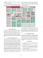
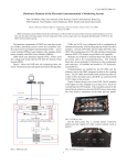
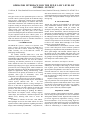
OPERATOR INTERFACE FOR THE PEP-II LOW LEVEL RF CONTROL SYSTEM* S. Allison, R. Claus Stanford Linear Accelerator Center, Stanford University, Stanford, CA 95309 U.S.A. Abstract This paper focuses on the operational aspects of the low level RF control system being built for the PEP-II storage rings at SLAC. Subsystems requiring major operational considerations include displays for monitor and control from UNIX workstations, slow feedback loops and control sequences residing on microprocessors, and various client applications in the existing SLAC Linear Collider (SLC) control system. Since commissioning of PEP-II RF is currently in-progress, only those parts of the control system used during this phase are discussed is detail. Based on past experience with the SLC control system, it is expected that effort expended during commissioning on a solid user interface will result in smoother transition to full reliable 24-hour-a-day operation. I. INTRODUCTION The PEP-II RF system 1 consists of 5 klystrons, each with 4 cavities, for the high energy ring (HER) and 3 klystrons, each with 2 cavities, for the low energy ring (LER). Currently, two of the HER RF stations are undergoing commissioning2 . For controls, each RF station has a VXI crate containing a VXI-based microprocessor running VxWorks, Allen-Bradley (AB) VME scanner card, and a collection of custom VXI modules used for low level RF controls, monitoring, and machine protection on arc and power faults. Outside the VXI crate, AB hardware is used for both the high voltage power supply (HVPS) and machine protection on slower changing inputs. UNIX workstations and a DEC computer are used for the operator interface and higher level applications. During commissioning, UNIX workstations are the primary X-terminals in use. During operation, other types of X-terminals, some with touchpanels, will supplement the workstations. The interface between the user and the hardware is constructed using the Experimental Physics and Industrial Control System (EPICS) took kit3 . To meet requirements, additional software is being developed inhouse or at other labs to supplement the standard EPICS software distribution. The tasks running on each RF VXI processor, also known as an Input Output Controller (IOC), provide data-scanning for updating the database, data archival for bumpless reboot, message logging, control loops, state transitions, calibration sequences, and channel access, allowing other hosts to access the database. In addition to software on the IOC, other EPICSbased packages are used on the UNIX stations for client operator interface (OPI) applications including the EPICS display editor and manager (EDD/DM)4 , a stripchart tool, 0-7803-4376-X/98/$10.00 1998 IEEE and various channel access tools. Existing SLC control system applications are being modified to perform channel access and to incorporate EPICS messages into the SLC message log. II. IOC SOFTWARE The RF IOC software was developed for an efficient and easily maintainable hardware interface. For the custom VXI modules, one EPICS record per module was developed, encapsulating all data and functions of that module. For the AB interface, software developed at APS and LANL was implemented as-is or modified slightly for the machine protection and high voltage systems5 . For the AB stepper motor card, device support software for the existing stepper motor record was developed. Additional software on top of this lower-level interface is being added to allow a user without detail knowledge of the control hardware to operate the RF station. The EPICS database is the bedrock of the RF control sys-tem. Some subsystems such as machine protection monitoring are implemented with just database records. To allow quick changes with minimal software impact, all RF stations use the same database and startup files, with distinctions defined by environment variables. The following packages are being added to supplement the basic database and provide a more usable system: Subroutine, Calculation, and Sequence Records Subroutine and calculation records provide data processing and analysis. An example of their usage is in the calculation of phase, power, and other related parameters from input in-phase and quadrature count values at 24 locations in the RF station at 2 hz. Also, for each component of the RF station, records providing summaries of severities and trips are processed on change and allow quick determination of trouble spots. Sequence records perform a series of simple control steps in a particular order with optional delays. Functions performed by sequence records include station reset, which executes the 12 steps needed to reset after a trip, reinitialization of the cavity tuner stepper motors, calibration of various system coefficients, and DAC update. SEQUENCE TASKS For more complex control sequences and loops, sequence tasks are being developed instead of a series of subroutine and sequence database records. Sequence tasks include one per *Work supported by Department of Energy, contract DE-AC03-76SF00515 cavity for cavity tuning, high voltage control for either station processing or to maintain the klystron drive power, DAC calibration, and station state control for transitioning to a desired run mode such as 2470 OFF, ON, PARK for allowing beam through the cavities while the station is offline, and TUNE or FM for station processing while no beam. For all sequence tasks, common features are incorporated especially for the user interface. Metered descriptive error messages are logged on abnormalities such as hardware errors and trips. Informational messages are logged on state changes, atlimit conditions, and other warnings. These conditions are also updated in the database as strings for real-time display. For control loops, ring buffers containing the most recent values of the loop parameters are kept as compress records in the database for diagnostic display purposes. Standard data-base records are provided so that the user can to turn the loop on and off, reset the loop to known good values, and change the loop period, gain, maximum actuator delta allowed in one cycle, and any other loop-specific constant. Bumpless Reboot Bumpless reboot is an IOC software package developed at LANL that saves all input constants, states, and other data as they are changed and then restores them as part of IOC initialization performed during reboot. This package is not part of the standard EPICS distribution but is considered critical for RF station operation and thus was implemented early in the project. To enhance the user interface, an optional informational message is now logged whenever an input is changed, providing a trail for debugging and determining system usage. Since so many fields in the database are modifiable, it is unreasonable to save every possible value since this would affect IOC performance due to the overhead of database monitoring and file IO. As a result, users must identify up-front what items they plan to change on the fly. As yet, this limitation has not proved to be too restricting Message Logging In addition to messages logged by subroutine records, sequence tasks, and bumpless reboot, errors are also logged by various EPICS system and database tasks. The message logging mechanism provided by the standard EPICS distribution does not integrate well with the existing SLC message logging, a system familiar to the users and heavily used. As a result, a remote procedure call (RPC) client task was developed which forwards all messages to a server in the SLC control system. III. OPI APPLICATIONS The PEP-II control system is built from both EPICS and the SLC control system. Both systems are high performance, distributed database-driven systems using microprocessors running real-time operating systems and performing control and monitoring of nearby hardware. Both provide similar basic client applications such as data archival, alarming, correlation plots, backup and restore, and knob- bing. Since users are already familiar with SLC applications, the only EPICS UNIX OPI tools enlisted for PEPII are those with either no equivalent or with highlydesirable features not available in the SLC control system. Currently, these tools include EDD/DM from LANL and a strip chart tool from TJNAF. EPICS channel access tools are also used by MATLAB data analysis programs written and used only by the RF engineers. EDD/DM EDD/DM provides real-time graphical displays. Though already rich in options, additional features are being added to EDD/DM by LANL to meet PEP-II requirements. Because of the variety of X-terminals in use, displays are now automatically scaled depending on screen size. To match similar capabilities on the SLC control system, the user now has the ability to select a printer or save-to-file. New kinds of buttons for selecting files, toggling a binary state, and printing have been added. The name behind any dynamic button is now made visible on request and put into the workstation paste buffer for use by other applications. The same displays are used, whenever possible, for all stations, with distinctions defined by macros. Except for diagnostic displays, all displays have a similar look and are consistent in the use of color-coding, button and datadisplay sizes, and placement of common items on all displays like the title, exit, print, and help buttons. The displays are hierarchical so the user starts at the high-level displays, which show overall summaries and statuses, and works down to the lower-level displays, providing more detail for a smaller part of the machine. In general, when going from one display to another, the parent display is killed to prevent clutter and manage resources. Buttons on the lower-level displays allow the user to go back up. Since displays must work on touchpanel X-terminals by people standing in a crowded and cluttered control room, the mouse usage is minimized by employing more realestate for display and control selections rather than using mousedriven popup or pulldown menus. The size of many control buttons and spacing between buttons are made for fingers rather than cursors. Currently, the displays have too much information and very few graphics per page, convenient for commissioning but not ideal for normal operation since the displays take too long to activate and are too dense. Colors are limited to a handful and, if possible, are combined with other attributes such as text and flashing for color-challenged users. For both summaries and individual items, green means OK, yellow means warning but with time for action, flashing yellow means a trip is imminent, red indicates the item is currently tripped and keeping the station off, flashing red indicates the item is the first to trip the station, and magenta means a hardware or software problem. Currently, all display backgrounds are light-colored with informational text in darker colors 2471 though this may change once operation is transferred to the dimly lit control room. In general, monitored data is displayed in black text with the current status shown using a colored rectangular box around the value. A small “DB” box resides next to STRIP CHART TOOL The strip chart tool is used during commissioning to monitor RF processing parameters such as cavity vacuums and gap voltages. Buttons on EPICS display allow users to start a variety of canned strip charts. Once active, the users may change any plot setup parameter for tailoring to their specific needs. This tool is quite popular and there are plans to allow it access to SLC control system data. IV. SLC CONTROL SYSTEM Channel access has been incorporated into a subset of SLC control system client applications to access the RF databases. EPICS database record naming conventions were developed so that the existing user interface could be adopted with few changes. During commissioning, the two mostly widely used applications are data archival and message logging. Other applications such as configuration save/restore, correlation plots, alarm handling, and multiknobs will be used later during full operation. For data archival, a channel access history buffer process was developed that periodically samples a subset of RF analog data points and saves them to files in the same format as SLC data. The user can then request plots of specific channels for any time period using the existing interface for SLC history. Canned plots of the more popular histo- the value which the user can select to get detailed database and other related information. These database displays have proved to be valuable for quick debugging and verification during commissioning. An example display follows: ries are available with one button push. An RPC server task was developed to receive messages from the IOCs and forward them to the SLC message handling facility. The existing message display system, with its rich set of features, can then be used to search for and list specific messages. V. ACKNOWLEDGEMENTS We would like to acknowledge P. Corredoura, T. Himel, D. Kerstiens, K. Krauter, R. Sass, and M. Zelazny for their efforts in either specifying or implementing the EPICS user interface. We would like to thank the SLC controls group for their help and patience during integration, and the EPICS collaboration for their invaluable assistance. REFERENCES [1] P. Corredoura et.al., “Low Level System Design for the PEP-II B Factory”, Proceedings of the 1995 IEEE Particle Accelerator Conference. [2] P. Corredoura et.al., “Commissioning Experience with the PEP-II Low-Level RF System”, these Proceedings. [3] Dalesio et.al., “The Experimental Physics and Industrial Control System Architecture: Past, Present, and Future”, ICALEPCS, October 1993. [4] P. Stanley, “EDD/DM User’s Manual 2.4”, March 1997. [5] Stein et.al., “Data Exchange from Allen-Bradley PLCBased Systems to EPICS, ICALEPCS, October 1995. 2472