1
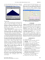
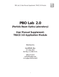
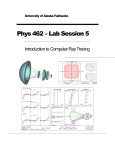
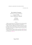
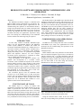
Proceedings of EPAC 2006, Edinburgh, Scotland
THPCH112
HIGH-LEVEL SOFTWARE FOR DIAMOND COMMISSIONING AND
OPERATION
R. Bartolini, C. Christou, I.P.S. Martin, J. Rowland, B. Singh
Diamond Light Source, Oxfordshire, UK.
The Diamond accelerator complex is controlled with
EPICS. Whilst generic applications are provided by the
EPICS toolkit, accelerator physics applications for the
commissioning and operation of the Diamond booster,
storage ring and transfer lines are mainly developed with
MATLAB. The MATLAB Middle Layer tools developed
at ALS and SPEAR3 have been extensively used and
extended with many new applications. Experience using
these tools during the commissioning of the Diamond
booster, transfer lines and storage ring are reported.
The flexible nature of the Middle Layer has allowed the
treatment of transfer lines, booster and storage ring to be
standardised, with many of the applications developed for
one part of the machine directly transferable to the rest.
The Middle Layer has also provided a systematic way of
managing machine data, and was easily extended to
separate data from transfer lines, booster and storage ring.
The Middle Layer communicates with the machine
from within MATLAB using either MATLAB Channel
Access (MCA) [6] or more recently LabCA [7]. Both
these packages can also be used directly as required.
INTRODUCTION
COMMISSIONING AND OPERATIONAL
APPLICATIONS
Abstract
As with many facilities worldwide, Diamond Light
Source uses the Experimental Physics and Industrial
Control System (EPICS) to monitor and control all
accelerator and beamline hardware [1]. Channel Access is
used as the interface to machine process variables (PVs),
and simple tasks such as monitoring, alarm handling,
display and setting of PVs are performed using EDM
panels and striptools. However, for more complex
accelerator physics applications, a collection of scripts
written in MATLAB and Python are used.
Early development of all high-level software was
possible with development of a so-called “virtual
accelerator” used to simulate the response of the electron
beam to changes in power supply currents [2]. The virtual
accelerator consists of the TRACY-II tracking code [3],
wrapped into EPICS device support. Using the virtual
accelerator, high-level applications were developed, tested
and de-bugged at an early stage, and as such were
available for day one of commissioning.
The accelerator physics tools for Diamond make
extensive use of the Middle Layer [4] and Accelerator
Toolbox (AT) [5] software packages developed in parallel
at the ALS and SPEAR3. These packages have been
adapted for use at Diamond and extended to cover
operation of the booster and transfer lines.
In addition to the existing tools that come as standard
with Middle Layer, many new applications have been
developed for the commissioning and operation of the
Diamond accelerators.
Transfer Lines
Beam emittance and Twiss parameters in both transfer
lines are measured using the emgtool GUI, a screenshot of
which is shown in Fig. 1 [8]. This application scans the
gradients of the first two quadrupoles in the transfer line,
recording the change in beam size using an OTR screen.
Fits are then made to the data using 2D Gaussian
distributions to extract the required values.
EXISTING MATLAB TOOLS
The Middle Layer is a library of routines that
communicate with either the machine hardware or the AT
model. It provides the user with a set of MATLAB
routines for standard operational tasks such as accessing
EPICS PVs, data measurement, storage and retrieval, unit
conversion, and orbit and optics correction. The software
is now mature and in routine use at several other facilities,
a key consideration when selecting it for use at Diamond.
07 Accelerator Technology
T04 Accelerator/Storage Ring Control Systems
Fig 1: Screenshot of tool for measuring the emittance and
Twiss parameters for the beam leaving the linac.
Using the measured Twiss values at the exit of the
linac, the corresponding Twiss parameters and dispersion
3065
THPCH112
Proceedings of EPAC 2006, Edinburgh, Scotland
function at the OTR screen after the first dipole in the
LTB are calculated by propagation with transfer matrices.
This enables the beam energy spread to be measured by
making additional fits to the beam size on the second
screen using the dispg application. The accuracy of this
measurement can be increased by varying the dispersion
function and beam size at the screen location using the
first 4 quadrupoles. The dispg application is now used
routinely when optimising both the energy and the energy
spread of the linac.
Online matching of the optics in the first transfer line is
performed using LTBQg which performs a least-squares
minimisation of the beam size along the transfer line
whilst constraining the Twiss parameters at the entrance
and exit to the pre-defined and desired values
respectively. Quadrupole gradients calculated using
external matching codes can also set to the machine
directly using LTBquadgui, and corresponding optics
accessed from the AT model.
Several applications exist for control of the beam
trajectory in the transfer lines. The first allows the user to
vary corrector magnet currents directly, whilst allowing
the BPM readings to be simultaneously monitored. A
script has been written to correct the beam trajectory to
the centre of the quadrupoles in a piecewise fashion along
the lines, and this has been used to check magnet and
BPM offsets. Trajectory correction to the BPM centres
using SVD can also be performed using the existing
Middle Layer PlotFamily application.
Control of the beam position and angle exiting the
transfer lines is performed by varying the last two
corrector magnet strengths simultaneously (see Fig. 2).
The applications developed to do this use the AT model to
calculate beam position and angle response at the septum
to changes in corrector magnet strength, and invert this
matrix using SVD to give the user full control over the
beam trajectory. This capability proved valuable during
commissioning, particularly for the set up of on- and offaxis injection into the storage ring.
Booster
The Diamond booster is a 100 MeV to 3 GeV ramping
synchrotron, cycling at 5 Hz. Many new high-level scripts
have been developed in MATLAB to be compatible with
the data format required for this machine, such as
functions to access vectors of BPM values during the
ramp and the waveforms and operating parameters of the
digital power supplies. These functions have all been
designed to be compatible with existing Middle Layer
functions.
Orbit correction during the ramp is possible due to the
ramping capabilities of the booster corrector magnets. The
application boosterorbitcorrectiongui automates this
process by acquiring vectors of BPM readings during the
ramp and performing an SVD of the orbit response matrix
to calculate vectors of corrector strengths as a function of
time. These vectors are then interpolated and scaled to the
main dipole current before uploading the ramp waveforms
to the individual corrector power supplies.
Python scripts have been developed to perform many
tasks for Diamond, and it is envisaged these will be
extended to provide applications for many of the routine
operational tasks. These scripts use powerful graphics
libraries to display real-time machine data such as first
turn orbit, closed orbit during the ramp and tune
measurements at injection calculated from the FFT of
free-running turn-by-turn data.
Fig 3: Screenshot of tool for plotting the closed orbit
during the booster ramp.
Fig 2: Screenshot of tool for controlling the position and
angle of the beam leaving the BTS.
3066
Tracking of the tunes during the ramp was key to
understanding and optimising booster performance during
commissioning. The horizontal and vertical fractional
tunes at injection and during the ramp can be measured
simultaneously using the two types of BPM turn-by-turn
data, and a MATLAB script has been written to acquire,
download and process the data before displaying the tune
signals as a function of time [9].
The booster RF cavity voltage ramp is also controllable
through EPICS. The MATLAB application developed for
this task contains in-built functions which allow the user
to create any desired linear, triangular, sinusoidal, sawtooth or arbitrary ramp waveform, or alternatively allows
any pre-defined ramp to be loaded from file (see Fig. 4).
07 Accelerator Technology
T04 Accelerator/Storage Ring Control Systems
Proceedings of EPAC 2006, Edinburgh, Scotland
Once the required RF voltage ramp has been established,
the application can then be used to upload the waveform
to the low-level RF controller [10].
THPCH112
Analysis and control of the storage ring optics is to be
carried out using the sropticsgui application. This
program allows the user to determine the linear optics
from any given set of quadrupole strengths using the AT
model, or conversely calculate quadrupole strengths
required to operate at any given tune point. A screenshot
of this application is shown in Fig. 5.
Fig 4: Screenshot of the RFramp application.
Storage Ring
Many of the tasks required in the storage ring can be
carried out using existing Middle Layer functions, the
majority of which are executable from within the
PlotFamily GUI. Beam-based alignment, orbit, tune and
chromaticity measurement and correction can all be
performed
using
these
tools.
Linear
optics
characterisation is to be carried out using LOCO [11], and
a GUI is available for this task.
During commissioning of the storage ring, first-turn
trajectory correction was performed using the
storageringcorrectorgui. This application is similar to
ones used in the transfer lines, in that it provides the user
with a direct interface to all corrector magnet currents,
simultaneously displaying all BPM first-turn readings.
A flexible orbit correction program has been developed
for storage ring commissioning. This program allows the
user to define which orbit data is used for orbit correction.
The user can choose between first turn data, orbit data
averaged over any number of turns or orbit data corrected
for saturated and non-linear BPM readings, all of which
can be averaged over many samples. The application also
allows the user to choose in which plane to apply
correction, to select a threshold for singular value
rejection and to apply only a fraction of the calculated
correction. This application was found to be particularly
useful during the early stages of storage ring
commissioning, when limited numbers of turns were
available, beam position varied shot-to-shot and
uncorrected beam amplitudes were large.
As in the booster, continuous tune measurements are
provided graphically from the free-running BPM turn-byturn data using an FFT. Closed orbit and first turn after
injection are displayed using Python tools. Simple
channel access calls to the BPM electronics will also
allow the user to view any desired turn number instead of
the first turn, a feature which proved valuable during
commissioning when investigating closure of the
injection bump.
07 Accelerator Technology
T04 Accelerator/Storage Ring Control Systems
Fig 5: Screenshot of sropticsgui application.
SUMMARY
High-level software development for the Diamond
accelerators has provided a set of tools for the
commissioning and operation of the machine which have
proved to be flexible and robust. These programs are
straightforward to develop and are adaptable as
circumstances require, often ‘on the fly’ during
commissioning shifts. Production of high-level software
is continuing for the remainder of the commissioning
period and for routine operation.
The authors would like to thank G. Portmann, A.
Terebilo, D. Robin, J. Safranek and J. Corbett for a
friendly and open collaboration regarding Middle Layer,
AT and LOCO. Contributions from all members of the
Diamond commissioning team in testing and developing
the high level software are also gratefully acknowledged.
REFERENCES
[1] www.aps.anl.gov/epics/
[2] R. Bartolini et al., Proc. PAC 2005, p. 3188-3190
[3] J. Bengtsson., “TRACY-2 User’s Manual”,
unpublished
[4] G. Portmann et al., Proc. PAC 2005, p.4009-4011
[5] A. Terebilo, Proc. PAC 2001, p.3203-3205
[6] A. Terebilo, Proc. ICALEPCS 2001, p. 543-544
[7] T. Straumann, “labCA – An EPICS Channel Access
Interface for SCILAB and MATLAB”,
www.slac.stanford.edu/comp/unix/package/epics/ext
ensions/labca/manual/
[8] C. Christou et al. “Commissioning of the Diamond
Pre-injector Linac”, these proceedings
[9] R. Bartolini et al., “Turn By Turn Data Acquisition
and Post Processing for the Diamond Booster and
Storage Ring”, these proceedings
[10] C. Christou et al., “The Diamond Light Source
Booster RF System”, these proceedings
[11] J. Safranek, Proc. EPAC 2002, p.1184-1186
3067