1
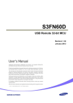
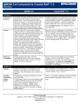
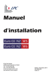
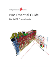
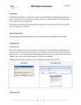
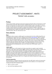
CEDR Transnational Road Research Programme Call 2012: Safety: Use of Vehicle Restraint Systems Funded by Belgium/Flanders, Germany, Ireland, Norway, Sweden, United Kingdom SAVeRS User manual for the SAVeRS Tool Deliverable D4.2 May 2015 Partners: University of Florence, Italy TRL Ltd, United Kingdom Swedish National Road and Transport Research Institute, Sweden Trinity College Dublin, Ireland Slovenian National Building and Civil Engineering Institute, Slovenia AIT Austrian Institute of Technology GmbH, Austria Parsons Brinckerhoff, United Kingdom Belgian Road Research Centre, Belgium CEDR Call 2012: Safety: Use of Vehicle Restraint Systems CEDR Call2012: Safety: Use of Vehicle Restraint Systems SAVeRS Selection of Appropriate Vehicle Restraint Systems User manual for the SAVeRS Tool Due date of deliverable: 31.12.2014 Actual submission date: 03.03.2015 Start date of project: 01.01.2013 End date of project: 31.12.2014 Authors of this deliverable: Bine Pingal, Slovenian National Building and Civil Engineering Institute, Slovenia Francesca La Torre, University of Florence, Italy PEB Project Managers: Alastair De Beer, National Road Authority, Ireland Mats Pettersson, Swedish Transport Administration, Sweden Version: May, 2015 i CEDR Call 2012: Safety: Use of Vehicle Restraint Systems Table of contents 1 2 INTRODUCTION ............................................................................................................... 3 VRS CLASS SELECTION................................................................................................. 5 2.1 STARTING THE VRS SELECTION ........................................................................... 5 2.2 ASSESSMENT OF SAFETY BARRIERS .................................................................. 7 2.3 ASSESSMENT OF CRASH CUSHIONS ................................................................. 22 2.4 ASSESSMENT OF TERMINALS ............................................................................. 26 3 SAFETY BARRIERS PLACEMENT ................................................................................ 30 4 MOTORCYCLE PROTECTION SYSTEMS .................................................................... 38 ii CEDR Call 2012: Safety: Use of Vehicle Restraint Systems 1 INTRODUCTION Dear user of the SAVeRS tool! Although we did our best to design the application as user friendly and as simple as possible, so that it should guide the user through its steps intuitively, we recognise the need to have a written manual at hand if the need arises. It will help you step-bystep to turn-on and use the application, and also shortly explain the main data, needed to calculate the output. You are kindly encouraged to read the SAVeRS Guideline before using the tool. NOTE: this tool is intended as a support to the designers and the decision makers but is not intended to replace the necessary designers’ expertise in selecting the most appropriate VRS or in defining where a VRS is needed. The SAVeRS team assumes no responsibility for any decision taken according to the SAVeRS Tool output. 3 CEDR Call 2012: Safety: Use of Vehicle Restraint Systems The tool consists of 3 different calculation procedures: To run any of the procedures included in the tool you need to enable the macros in your excel if these are not automatically enabled. If you get an error indicating that the system cannot run macros due to a protection, restart the program and enable the content in the top line as shown below. For any inquiry or feedback please refer to [email protected] Let’s get started! 4 CEDR Call 2012: Safety: Use of Vehicle Restraint Systems 2 VRS CLASS SELECTION 2.1 STARTING THE VRS SELECTION Step 1 Rename the xlsm file with your project’s name. Run the xlsm file and enable the macros as explained above. Step 2 Open the detailed analysis spreadsheet by clicking on the “VRS Class selection (barriers/crash cushions/terminals)” button. Confirm the information window by clicking “OK”. SCREENVIEW 1 5 CEDR Call 2012: Safety: Use of Vehicle Restraint Systems Note: This section of the tool is NOT designed to recommend using/not using a VRS and it also doesn’t suggest a place where to put it. It is intended as a tool for comparing different classes and types of VRS, once it has already been decided that a VRS will be put in place. If you wish to see or review the criteria that define where a placement of VRS is recommended, open the “Safety Barriers Placement” or the “Guidelines” by clicking on the appropriate button. In the top section of the VRS selection procedure a description of the different types of cells is given. Beside there are 4 options (buttons): Run crash calculation Reset for a new calculation Evaluate Crash Cushions Evaluate Terminals The use of the different buttons is described later in the manual. SCREENVIEW 2 NOTE: You need to have completed the crash calculation for the barriers prior to assessing crash cushions and terminals. If you have already completed the crash calculation (step 3) and you wish to evaluate crash cushions, please proceed to chapter 2.3 of this manual. If you have already completed the crash calculation (step 3) and you wish to evaluate terminals, please proceed to chapter 2.4 of this manual. 6 CEDR Call 2012: Safety: Use of Vehicle Restraint Systems 2.2 ASSESSMENT OF SAFETY BARRIERS Step 3 In the “Road and traffic” section, start with choosing a crash model. Click on a green cell and choose a crash model from the list by clicking on the grey arrow that appears at the right-bottom corner of the cell. Select a model and confirm by clicking on it. Use the same procedure to choose a road type (single/dual carriageway). Then go on and input individual numbers for different required data. Choose “class of containment level” for the VRS using the same procedure as before with the dropdown menu. Note1: if none of the offered crash models meets your requirements, you can make your own model by clicking “Add a new crash model” button. You will be redirected to a new window where you have to input the required data. The ones marked in red are necessary to properly run the tool. If you are setting only the model for one type of road (single or dual carriageway) you can ignore the red cells in the other part of the sheet. Note2: If you do not input a certain data required for the calculation in the “Road and traffic” section, a pop-up window will appear, notifying you to either input the data or that the value will automatically be set to 0 in order to enable the calculation. You can read a short description of data labels in the list below. List and short glossary of data labels: Number of lanes: number of lanes in the analysed carriageway Average annual daily traffic (AADT): number of vehicles per day (average per carriageway) Heavy goods vehicles (HGV) proportion: percentage of HGVs in the AADT 7 CEDR Call 2012: Safety: Use of Vehicle Restraint Systems Traffic growth expected: estimated traffic growth per year for design years (in %) Volume exceeds 1000 veh/h/ln (%): Proportion of the total AADT that travels during hours where the average volume per hour exceeds 1000 vehicles per hour per lane (%) (only used for motorways) Segment length (m): total length of segment of the road that the user wants to analyse (in m). The tool assumes that the barrier length is equal to the segment length. Curve radius (m): radius of a specific curve in the analyzed road segment (horizontal curvature); in meters. This is used to assess the total number of crashes and it is always a positive number (independently of the edge analysed). Curve length (m): length of the specific curve above including the spirals (clothoids) length; in meters. If the segment analyzed is only part of a curve the whole curve length has to be used as input. Gradient (%): average longitudinal inclination the road segment (negative if downhill); in percentage Outside shoulder width (m): width of the shoulder on the outer side of the carriageway Inside shoulder width (m): width of the shoulder on the inner side of the carriageway towards the median (only for motorways) Speed limit: legal or posted speed limit on a given road km/h (only for the Swedish 2 lane model) 8 CEDR Call 2012: Safety: Use of Vehicle Restraint Systems Spirals (for two-lane rural roads): transition curve (also called clothoids) between a straight and a curve or between two curves (only for the 2 lane models) Percentage of rumble strips (%): presence of rumble strips in the straight portions of the analysed segment; in percentages compared to the length of the straights Lane width (m): width of the driving lane; in meters Class of containment level: containment level of the VRS defined according to EN1317-2:2010 – Note: for choosing this input, use the same procedure as when choosing crash model or road type – drop down menu. Start year: first year of the design period (included) End Year: last year of the design period (included). The number of design years (design period) will be calculated by the tool as (end year-start year) + 1 Interest-inflation Rate: this terms is needed for the cost actualization and is given as the difference between the interest rate and the inflation rate 9 CEDR Call 2012: Safety: Use of Vehicle Restraint Systems SCREENVIEW 3 After you have input all the required data, click the blue “Run crash calculation” button at the top of the page. Step 4 In the “Predicted crash condition” section the results of the crash calculation are shown, based on your previous choice of crash model. However you can choose to replace the calculated ROR crashes by clicking on the red “REPLACE calculated ROR crashes” button. A new window will then appear where you input the passenger car and HGV total expected crashes in the design period on the analysed edge and confirm your choice with “OK”. Note: if you wish to restore the pre-calculated data for ROR crashes, click the grey “RESTORE calculated ROR crashes” button. The values will be restored to SAVeRS default. Proceed with choosing the “crash distributions” for passenger cars and for HGV by using the “drop-down menu” as before. In the V0 release there are 6 distributions for HGVs and 6 distributions for passenger cars (PC). For the selection of the most appropriate distribution the following table can be used as a guideline but a different selection can be made based on local speed and traffic conditions. When 2 alternatives are given the less severe is written in green while the more severe is written in red. Any selection can be replaced by choosing the USER DEFINED option but in this case the user has to define a specific IKE distribution. 10 CEDR Call 2012: Safety: Use of Vehicle Restraint Systems Type of road Motorway with a speed limit above 100 km/h Divided Highway or motorway with a speed limit of 100 km/h or below Undivided two-lane twoways rural roads Lanes Edge 2 Roadside 2 Median 3 Roadside 3 Median 2 Roadside 2 Median 3 Roadside 3 Median 2 Roadside HGV distribution PC distribution Motorway Roadside_2 lanes Germany Dual Carr_Motorway or US Dual Carriageways Germany Dual Carr_Motorway or US Dual Carriageways Germany Dual Carr_Motorway or US Dual Carriageways Germany Dual Carr_Motorway or US Dual Carriageways Germany Dual Carr_Highway or US Dual Carriageways Germany Dual Carr_Highway or US Dual Carriageways Germany Dual Carr_Highway or US Dual Carriageways Germany Dual Carr_Highway or US Dual Carriageways Germany Single Carriageways (*) or US Single Carriageways Motorway Median_2 lanes Motorway Roadside_3 lanes Motorway Median_3 lanes Motorway Roadside_2 lanes Motorway Median_2 lanes Motorway Roadside_3 lanes Motorway Median_3 lanes RSAPV3 Undivided_fric=0.45-0.6 (*) The German distribution shows a higher probability of having and IKE above the VRSCL only for the N1 class. Once the IKE distributions have been selected, click the blue “Run IKE calculation” button shown in the Screenview 4.1 and the crash statistics will be shown in the right portion of the predicted crash conditions section, as shown in the Screenview 4.2. SCREENVIEW 4.1 11 CEDR Call 2012: Safety: Use of Vehicle Restraint Systems SCREENVIEW 4.2 List and short glossary of data labels in the predicted crash conditions section: ROR likelihood cars: computed likelihood that the ROR crash of a passenger car will happen on the road with given parameters ROR likelihood trucks & buses (HGV): computed likelihood that the ROR crash of a HGV (trucks/buses) will happen on the road with given parameters ROR crashes: single vehicle run-off-road crashes Encroachment HGV Multiplier: this term is the ratio between the HGV ROR risk (number of HGV ROR crashes divided by the HGV km travelled) and the total ROR risk (number of ROR crashes divided by the total km travelled). For more details refer to chapter 3.3.2 and 3.3.3 of the Guideline. This value is linked to the model chosen and therefore it can be changed only by defining a new model (see Step 3) or by manipulating the existing ones (not recommended). Crash distribution: Impact Kinetic Energy distribution for passenger cars and for HGVs. For more 12 CEDR Call 2012: Safety: Use of Vehicle Restraint Systems details refer to chapter 3.1 of the Guideline. You can choose one of the pre-existing distributions or define a new one. To do this, click on the “Edit USER Defined passenger car impact” or “Edit USER Defined HGV impact”. Overall design level (cars+HGV): % of crashes that are potentially contained by the barrier (with IKE not above the containment level of the barrier). Design level: % of crashes that are potentially contained by the barrier (with IKE not above the containment level of the barrier) for a specific vehicle category (cars or HGV). Potential penetrations: number of crashes in the design period that will potentially penetrate the barrier (with IKE above the VRS containment level). Potential penetrations return time (years): this is calculated as 1/(number of potential penetrations/design period) Potentially contained crashes: number of crashes in the design period that are potentially contained by the barrier (with IKE not above the VRS containment level). Potential penetrations return time/km (years/km): this is calculated as 1/(number of potentially contained penetrations/(design period x project length in km)) 13 CEDR Call 2012: Safety: Use of Vehicle Restraint Systems Step 5 In the “Severity distribution function” section you have to choose the roadside configuration, using the drop down menu. You can also choose an option “user defined”. To change user defined distributions or hazard aggressiveness factors click on “manage severity distribution”. A new spreadsheet “Severity Distribution Functions” will appear. Be aware that changing any data in this spreadsheet directly influences the calculation procedure of the application. If you select “Verge (roadside)” as a roadside you will also be required to define a hazard type. If the roadside is a tall bridge or a median the roadside hazard type is not applicable and you will not be able to select it. A “tall bridge” is considered a bridge with a drop from the edge to the ground below equal or greater than 10 m. In version V0 of the tool the following set of hazards are considered but a user defined aggressiveness factor can be used. Hazard type Aggressiveness factor No specific hazard 1 Brick/Masonry Wall 1.3 Bridge structure/abutment/rigid wall 1.7 Cabinets (communications/power/electricity supply) 2 Chain link/Welded Mesh/Palisade 0.8 Close boarded fence 0.9 Culvert 1.8 Ditch 0.8 Environmental/noise Barrier (concrete/timber) 1.8 Environmental/noise Barrier (earth) 0.8 Lagoon/Water > 1.00 m depth 1.5 Rigid sign/lighting/electricity post/pole and similar (non passively safe) 1.8 Rock 2.5 14 CEDR Call 2012: Safety: Use of Vehicle Restraint Systems 1.5 Slope_Steep/high slope 2 Slope_Very steep/high slope 2.5 Slope_Extremely steep/high slope 2 Tree For the definition of the slope configuration the criteria given below could be used (based on the UK RRRAP method) but different definitions could be applied considering also the requirements of different national standards. Slope Falling 1:1 or steeper Falling 1:1.5 - 1:1 Falling 1:2 - 1:1.5 Falling 1:2.5 - 1:2 Falling 1:2 - 1:3 Rising 1:1.5 or steeper Height equal or above (m) Slope risk 1.0 1.5 2.0 2.5 5.0 0.5 Slope_Extremely steep/high slope Slope_Very steep/high slope Slope_Very steep/high slope Slope_Very steep/high slope Slope_Steep/high slope Slope_Steep/high slope All other embankment/cut conditions, if a barrier is required, can be considered as “no specific hazard”. After selecting the roadside configuration and the hazard (if applicable) click on the “Runs severity distribution calculation” button and the results of the severity distribution analysis will be shown. You can read a short description of the data labels of the Severity Distribution section in the list below. List and short glossary of data labels: Type of roadside: choose from the dropdown menu; bridge (high/low risk), median or verge Fatality (K): proportion of crashes with fatalities among humans out of all reported crashes; in percentage 15 CEDR Call 2012: Safety: Use of Vehicle Restraint Systems Incapacitating injury (A): proportion of crashes with severe, incapacitating injuries to humans out of all reported crashes; in percentage Non-incapacitating injury (B): proportion of crashes with minor, nonincapacitating injuries to humans out of all reported crashes; in percentage Possible injury (C): proportion of crashes with possible injuries to humans out of all reported crashes; in percentage % of events (contained): distribution of the contained by severity % of events (penetrated): distribution of the events that potentially penetrate the barrier by severity Number of events in design life: total events by severity that are expected in the design period Return time of a fatal crash (years): 1/(expected number of fatal crashes x design period) Return time of a fatality / km (years): 1/(expected number of fatal crashes x design period x project length in km) events potentially Equivalent fatal crashes per km per year Total societal costs/unit fatal cost divided by the design period and the project length in km. 16 CEDR Call 2012: Safety: Use of Vehicle Restraint Systems SCREENVIEW 5 Step 6 In the “cost benefit” section you can choose the country for which the costs related to VRS maintenance and construction are available. Choose one using drop-down menu. Under “solutions” you choose the exact type of a VRS, for which the costs will be shown. Choose one per line using the drop-down menu. Not all lines need to be filled. NOTE: when an analysis is conducted for a certain VRS class (e.g. H2) and a given country is selected (e.g. Italy), all the barriers for that VRS class and that country (e.g. all H2 barriers listed for Italy) will be shown. Prior to selecting a solution the user MUST check: the compatibility with the required usage (e.g. if the barrier is to be installed on a bridge or on the top of a wall a roadside barrier tested for installation on soil cannot be used); 17 CEDR Call 2012: Safety: Use of Vehicle Restraint Systems the compatibility of the working width with the available space if different solutions are given for barriers with different working widths. If you want to add barrier types click on the “Add barrier types to the drop” button. A new spreadsheet “Barriers” will appear. Be aware that changing any data in this spreadsheet directly influences the calculating procedure of the application. The data labelled as “SAVeRS” in the last column cannot be edited in order to ensure the Road Administration that if one of these solutions is picked the input values are not manipulated. If you are a Road Administration and would like to amend one of these values of add new solutions blocked and labelled as “SAVeRS” please write to [email protected] and we will amend the data and issue a new release. In this spreadsheet you can also add a new country dataset by clicking on the red button at the bottom of the sheet. The system will ask you to indicate the country and the currency. You cannot edit directly the table. You can read a short description of the data labels in the list below. List and short glossary of data labels: Solutions: a set of VRS according to countries for which different lifetime and construction costs are available Crashes: the total number of ROR crashes calculated in step 4 18 CEDR Call 2012: Safety: Use of Vehicle Restraint Systems Injury costs: calculated costs of injury crashes (mathematical formula explained in the spreadsheet at the bottom) Construction cost: estimated costs of constructing a new VRS Crash repair: cost of the VRS repair due to crashes (total in the design period) Maintenance cost: cost of maintenance of the VRS through its lifetime Lifetime cost: cost of a construction and predicted maintenance activities throughout the whole expected lifetime of a VRS (mathematical formula explained in the spreadsheet at the bottom) Currency: currency of the country that the costs are calculated for Class: containment level of the according to EN1317-2:2010 Country: country for which VRS costs are calculated for SCREENVIEW 6a 19 VRS defined CEDR Call 2012: Safety: Use of Vehicle Restraint Systems The unit costs of the barriers used are summarized in the last table of the sheet as shown in Screenview 6b. SCREENVIEW 6b Printing the results To print the results of the calculation in a pdf file just click on the “Prints results in pdf” file at the end of the page. Note: the tool will suggest a name which is based on the EXCEL file name. If the file exists it will be overwritten without any warning. The file is usually saved in your “Documents” folder but this could vary depending on the configuration of your computer. The final table of the detailed analysis can also be copied and pasted in another excel or word file to compare barriers of different classes (for each run only one VRS class can be analysed). Resetting the calculation If you wish to make another calculation, or you wish to empty all the cells, simply click the grey “Reset for a new calculation” button at the top of the page. Then start the data input as described from Step 3 onwards. After you have input all required data in the “Road and traffic” section, you have to click on the “run crash calculation” button and the other sections will appear. Continue with the procedure as described from Step 4 onwards. 20 CEDR Call 2012: Safety: Use of Vehicle Restraint Systems Note: when you reset for a new calculation or you change any of the input data, sections 2-4 will disappear. Only section “Road and traffic” will be visible. Buttons at the bottom of the spreadsheet There are additional 3 buttons at the bottom of the “Detailed analysis” spreadsheet. Show CMF sheets – click this option if you wish to access and modify default CMF calculations. Two new spreadsheets “CMF Motorways” and “CMF Rural Roads” will appear. Be aware that changing any data in these spreadsheets directly influences the calculating procedure of the application. Show all hidden sheets – click this option if you wish to see, access and manipulate all the data that are needed for the calculation process in the application. Be aware that changing any data in these spreadsheets directly influences the calculating procedure of the application. The white and grey cells are blocked and the user will not be able to change them. Hide all sheets – click this option to hide all sheets that are not necessary for the use of the application. The application will still run in the background. SCREENVIEW 7 21 CEDR Call 2012: Safety: Use of Vehicle Restraint Systems 2.3 ASSESSMENT OF CRASH CUSHIONS When after Step 3 of the barriers assessment you decide to click the green “Evaluate crash cushions” button, a new spreadsheet will automatically appear. It consists of 3 basic sections: Upper section Predicted crash conditions Predicted crash speed conditions Step 1 In the upper section the inputs for the evaluation of crash cushions are given. The grey cells are taken directly from the detailed assessment of the barriers. The user has to provide inputs in the light orange cells. You can read a short description of the data labels in the list below. List and short glossary of data labels: Number of crash cushions: number of cushions you have in your segment Shoulder width (m): with of the shoulder adjacent to the cushion Barrier offset (m): if the side of the cushion is not on the outer edge of the shoulder the distance between the edge of the shoulder and the closest edge of the cushion has to be given. Influence length per crash cushion (m): length of a section in approach to the crash cushion where a ROR can affect the cushion (in meters). The default is calculated as the 22 CEDR Call 2012: Safety: Use of Vehicle Restraint Systems lower value of the Run Out Length except where the crash cushion is located in a diverge area. In the latter case the upper value is taken. Please refer to the Guide for more details. Design speed: the design speed is usually higher than the posted speed. For existing roads it might be unknown and some countries provide indications on how to determine it (e.g. the posted speed limit + 10 km/h or 85th percentile of the actual speed distribution). Diverge area: an area where motorway separates in two trajectories in the same direction Segment length: overall analysis length (this is taken from the Detailed Analysis sheet) Road type: single/dual carriageway road (this is taken from the Detailed Analysis sheet) SCREENVIEW 1 Step 2 In the “predicted crash condition section” you only view results of the pre-calculated data and you are not supposed to input any new data. You can read a short description of the data labels in the list below. 23 CEDR Call 2012: Safety: Use of Vehicle Restraint Systems SCREENVIEW 2 List and short glossary of data labels: Diverge area multiplier: factor that accounts for the increased number of crashed in diverge areas, only applicable for motorways (for more details refer to chapter 5.1 of the Guideline) ROR likelihood cars: computed likelihood that the ROR crash of a passenger car will happen on the analysed road in the cushion approach sections ROR likelihood trucks & buses (HGV): computed likelihood that the ROR crash involving a HGV (trucks/buses) will happen on the analysed road in the cushion approach sections ROR likelihood TOTAL: total likelihood that the ROR crash will happen on the analysed road in the cushion approach sections Possible cushion related crashes: computed likelihood of cushion related crash on the analysed road in the cushion approach sections Possible cushion related crashes per year per single device: computed likelihood of cushion related crash on the analysed road in the cushion approach sections per year per single device 24 CEDR Call 2012: Safety: Use of Vehicle Restraint Systems Return time of a possible cushion related crash (years per device): 1/Possible cushion related crashes per year per single device Step 3 In section “predicted crash speed conditions” you have to choose the crash cushion class by using the drop-down menu. Other data are pre-calculated and do not require additional input. You can a read short description of the data labels in the list below. List and short glossary of data labels: Crash cushion class: class of a crash cushion according to EN1317-3:2010 Car crash distribution: crash distribution selected in the barrier analysis for passenger cars Car crashes above max test speed: computed likelihood of a crash happening at a speed higher than the maximum speed the crash cushion is tested for Total in the design life: computed likelihood of a crash happening at a speed higher than the maximum speed the crash cushion is tested for, in the whole expected lifetime of a crash cushion Return time (years for the project): 1/(total in the design life x design period) Return time (years per device): 1/(total in the design life x design period x number of devices) 25 CEDR Call 2012: Safety: Use of Vehicle Restraint Systems SCREENVIEW 3 Printing the results To print the results of the calculation in a pdf file just click on the “Prints results in pdf” file at the end of the page. Note: the tool will suggest a name which is based on the EXCEL file name. If the file exists it will be overwritten without any warning. 2.4 ASSESSMENT OF TERMINALS When after Step 3 of the barriers assessment you decide to click the green “Evaluate terminals” button, a new spreadsheet will automatically appear. It consists of 3 basic sections: Upper section Predicted crash conditions Predicted crash speed conditions As the evaluation procedure and spreadsheet for evaluating terminals is almost exactly the same as for evaluating crash cushions, please refer to the above described steps (in the evaluation of crash cushions) for making the evaluation of terminals. You can read short a description of the data labels in the list below. List and short glossary of data labels: Number of terminals: number of terminals you have in your segment Shoulder width (m): with of the shoulder adjacent to the cushion 26 CEDR Call 2012: Safety: Use of Vehicle Restraint Systems Barrier offset (m): if the side of the terminal is not on the outer edge of the shoulder the distance between the edge of the shoulder and the closest edge of the terminal has to be given. Influence length per terminal (m): length of a section in approach to the terminal where a ROR can affect the device (in meters). The default is calculated as the lower value of the Run Out Length. Please refer to the Guide for more details. Design speed: the design speed is usually higher than the posted speed. For existing roads it might be unknown and some countries provide indications on how to determine it (e.g. the posted speed limit + 10 km/h or 85th percentile of the actual speed distribution). Segment length: overall analysis length (this is taken from the Detailed Analysis sheet) Road type: single/dual carriageway road (this is taken from the Detailed Analysis sheet) SCREENVIEW 1 ROR likelihood cars: computed likelihood that a ROR crash of a passenger car will happen on the analysed road in the terminal approach sections 27 CEDR Call 2012: Safety: Use of Vehicle Restraint Systems ROR likelihood trucks & buses (HGV): computed likelihood that a ROR crash involving a HGV (trucks/buses) will happen on the analysed road in the terminal approach sections ROR likelihood TOTAL: total likelihood that a ROR crash will happen on the analysed road in the terminal approach sections Possible terminal related crashes: computed likelihood of terminal related crash on the analysed road in the terminal approach sections Possible terminal related crashes per year per single device: computed likelihood of terminal related crash on the analysed road in the terminal approach sections per year per single device Return time of a possible terminal related crash (years): 1/ Possible terminal related crashes per year per single device SCREENVIEW 2 Terminal class: terminal class according to ENV 1317-4 Car crash distribution: crash distribution selected in the barrier analysis for passenger cars 28 CEDR Call 2012: Safety: Use of Vehicle Restraint Systems Car crashes above max test speed: computed likelihood of a crash happening at speeds higher than the terminal is tested for Total in the design life: computed likelihood of a crash happening at speeds higher than the terminal is tested for, in the whole expected lifetime of a terminal Return time (years for the project): 1/(total in the design life x design period) Return time (years per device): 1/(total in the design life x design period x number of devices) SCREENVIEW 3 Printing the results To print the results of the calculation in a pdf file just click on the “Prints results in pdf” file at the end of the page. Note: the tool will suggest a name which is based on the EXCEL file name. If the file exists it will be overwritten without any warning. The file is usually saved in your “Documents” folder but this could vary depending on the configuration of your computer. 29 CEDR Call 2012: Safety: Use of Vehicle Restraint Systems 3 SAFETY BARRIERS PLACEMENT Step 1 Rename the xlsm file with your projects name. Run the xlsm file and enable the macros as explained above. Note: you can use the same file used for the VRS selection as this part of the tool will not overwrite any data from the VRS selection section. Step 2 Open the safety barriers placement spreadsheet by clicking on the “Safety Barriers Placement” button. SCREENVIEW 1 Note: This section of the tool is NOT designed to recommend using/not using a VRS and it also doesn’t suggest a place where to put it. It is intended as a tool for comparing different standards for the definition of the clear zone and to evaluate the range of potential length of needs. The user should read section 2 of the Guideline prior to using this section of the tool. 30 CEDR Call 2012: Safety: Use of Vehicle Restraint Systems Step 3 The barrier placement procedure conducts two evaluations: the clear zone evaluation where the available distance between the travelled way and the hazard is compared with the clear zone required by the different standards analysed in Deliverable D1.1 of the SAVeRS Project. For more details on each method please refer to that deliverable (downloadable @ www.saversproject.com); the Length of Need (LON) evaluation based on the criteria described in chapter 2.6 of the Guideline. The input section in the top left (see screenview 2) refers to the evaluation of the clear zone and the inputs are described below. List and short glossary of data labels: Road type: road configuration which can be dual (divided) or single (undivided) carriageway Directions: this is to choose between dual and single carriageway and it is required for the LON calculation Segments: the transversal section between the travelled way and the hazard needs to be described in terms of single segments with a constant slope, as shown in the screenview 3. The first segment is always the shoulder. The transversal slope has to be selected from a dropdown menu. In the different methods slopes higher than 1:3 (in embankments) and 1:2 (in cuts) are not allowed. For higher 31 CEDR Call 2012: Safety: Use of Vehicle Restraint Systems slopes you cannot use this tool. The total distance is calculated automatically. Difference in height between the hazard base and the pavement edge (dH in m): difference in elevation between the road edge and the hazard base (see screenview 3). When the road is higher than the hazard base this value is negative. Type of obstacle: select one in the drop down menu between isolated point as a single sign / multiple point as a line of trees / linear as an acoustic barrier Curvature: select one in the drop down menu. If you are analysing a straight skip the next two inputs Edge: if you are analysing a curve you need to specify if you are analysing the inner edge (where the radius is smaller) or the outer (where the radius is larger) of the specific carriageway Radius: if you are analysing a curve you need to specify the design radius (usually in the axle of the carriageway) Speed limit: legal or posted speed limit Design speed: the design speed is usually higher than the posted speed. For existing roads it might be unknown and some countries provide indications on how to determine it (e.g. the posted speed limit + 10 km/h or 85th percentile of the actual speed distribution). This value is required also for the LON calculation 32 CEDR Call 2012: Safety: Use of Vehicle Restraint Systems AADT: annual average daily traffic for the entire carriageway (for divided motorways it is only the traffic in one direction). This value is required also for the LON calculation SCREENVIEW 2 33 CEDR Call 2012: Safety: Use of Vehicle Restraint Systems SCREENVIEW 3 To run the clear zone evaluation click on the “Run the CLEAR ZONE evaluation” button. The output of the clear zone evaluation is a check with reference to all the different standards and a set of warnings, as in the example below. 34 CEDR Call 2012: Safety: Use of Vehicle Restraint Systems SCREENVIEW 4 Every time you change an input the output section will be cleared. If you want to clear also the input section, click on “Reset for a new calculation”. 35 CEDR Call 2012: Safety: Use of Vehicle Restraint Systems The Length of Need (LON) section is below the figure and is shown in screenview 5. SCREENVIEW 5 To run the LON calculation the design speed and the AADT need to be defined as describe above together with additional inputs that are summarized below. List and short glossary of data labels: Distance between the front of the barrier and the front of the obstacle Distance measured transversal to the road section from the front of the barrier facing the traffic to the side of the hazard closest to the travelled way Distance between the front of the barrier and the rear of the obstacle Distance measured transversal to the road section from the front of the barrier facing the traffic to the side of the hazard farthest to the travelled way Working width of the barrier Value in m (not class) of the working width determined in the Type Testing of the barrier to be installed (as in EN1317-2:2010) Distance between the front of the barrier and the adjacent travelled lane Distance measured transversal to the road section from the edge of the lane closest to the hazard to the side of the safety barrier facing the traffic Distance between the front of the barrier and the opposing travelled Distance measured transversal to the road section from the closest edge of the 36 CEDR Call 2012: Safety: Use of Vehicle Restraint Systems lane opposite lane to the side of the safety barrier facing the traffic (this is required only for bidirectional roads) To run the LON evaluation click on the “Run the Length of Need evaluation” button. The output of the LON evaluation is the range of required LONs as described in the Guideline, as shown in the example below. NOTE: the LON is the extension of VRS where the barrier has to offer the full containment. Before that you need a terminal and an anchoring section could be required depending on the VRS specifications and on the type of terminal used. Every time you change an input the output section will be cleared. Printing the results To print the results of the calculation in a pdf file just click on the “Prints results in pdf” file at the end of the page. Note: the tool will suggest a name which is based on the EXCEL file name. If the file exists it will be overwritten without any warning. The file is usually saved in your “Documents” folder but this could vary depending on the configuration of your computer. 37 CEDR Call 2012: Safety: Use of Vehicle Restraint Systems 4 MOTORCYCLE PROTECTION SYSTEMS Step 1 Rename the xlsm file with your projects name. Run the xlsm file and enable the macros as explained above. Note: you can use the same file used for the VRS selection as this part of the tool will not overwrite any data from the VRS selection section. Step 2 Open the MPS spreadsheet by clicking on the “Motorcycles Protection Systems” button. SCREENVIEW 1 The MPS section has a single area: the user is required to provide a set of inputs as shown in screenview 2 where the different inputs are described here in summary. 38 CEDR Call 2012: Safety: Use of Vehicle Restraint Systems List and short glossary of data labels: Infrastructure analysed: this is different from the road configuration and it allows also analysing junctions as these are extremely critical for powered two wheelers Curvature: select one in the drop down menu. If you are analysing a straight skip the next two inputs Edge: if you are analysing a curve you need to specify it you are analysing the inner edge (where the radius is smaller) or the outer (where the radius is larger) of the specific carriageway Radius: if you are analysing a curve you need to specify the design radius (usually in the axle of the carriageway) A set of potential high risk conditions are also listed (refer to section 6 of the Guideline for more details). For each of these menus, the user has to pick “YES”, “NO” or “NOT APPLICABLE”. The analysis will not run if a selection is not made for all the menus. 39 CEDR Call 2012: Safety: Use of Vehicle Restraint Systems SCREENVIEW 2 To run the MPS evaluation click on the “Run MPS needs evaluation” button. 40 CEDR Call 2012: Safety: Use of Vehicle Restraint Systems The output can be of the following: To clear the input screen, click on the “Reset for a new evaluation” button. Printing the results To print the results of the calculation in a pdf file just click on the “Prints results in pdf” file at the end of the page. Note: the tool will suggest a name which is based on the EXCEL file name. If the file exists it will be overwritten without any warning. The file is usually saved in your “Documents” folder but this could vary depending on the configuration of your computer. 41