Download PUB LDS 931 SaferBraIn_D3.4 Decision support system

Transcript
Loughborough University
Institutional Repository
Innovative guidelines and
tools for vulnerable road
users safety in India and
Brazil [SaferBraIn]: D3.4
Decision Supporting System
This item was submitted to Loughborough University's Institutional Repository
by the/an author.
Citation:
TRIPODI, A. ...
et al, 2011.
Innovative guidelines and tools for
vulnerable road users safety in India and Brazil [SaferBraIn]:
D3.4 Decision
Supporting System, 87pp.
Additional Information:
•
D3.4 Decision Supporting System
Metadata Record: https://dspace.lboro.ac.uk/2134/19158
Version: Accepted for publication
Publisher: European (7th RTD Framework Programme)
Rights: This work is made available according to the conditions of the Creative
Commons Attribution-NonCommercial-NoDerivatives 4.0 International (CC BYNC-ND 4.0) licence. Full details of this licence are available at: https://creativecommons.org/licenses/bync-nd/4.0/
Please cite the published version.
SEVENTH FRAMEWORK PROGRAMME
THEME 7 – TRANSPORT (INCLUDING AERONAUTICS)
Collaborative Project
Project Acronym: Safer BraIn
Project Coordinator: CTL – Centro di Ricerca per il Trasporto e la Logistica – Roma
(Italy)
Proposal full title: Innovative Guidelines and Tools for Vulnerable Road Users
Safety in India and Brazil
Grant Agreement n°: 233994
Document Title: Decision Support System
Author(s): Antonino Tripodi (CTL), Claire Quigley, Ruth Sims (Loughborough), Martijn
van de Leur, Angela van der Kloof (Mobycon), Alessandro Fornasiero, Roberto
Carroccia (ITRoma)
Summary: The document provides an overview of objectives, characteristics, functions
of the DSS, as well as a guide for its use.
Status: Final
Distribution: All Partners
Document ID: SB-CTL-WP3_D3.4
Date: March 2011
Project start: 1st October 2009
Duration: 30 Months
SB-CTL-WP3_D3.4
Grant Agreement n°233994
Executive summary
The SaferBraIn project is a Specific International Cooperative Actions developed as part of
the European Commission 7th Framework Programme. The main aim of the project is to
increase the level of safety of the whole road transport system and its components in
Emerging Economies, focussing the attention on Vulnerable Road Users (pedestrians and
cyclists).
Specifically, SaferBraIn develops innovative methodologies and tools for planning, designing
and maintaining safe infrastructures in India and Brazil.
In the Work Package 3 of SaferBraIn, an innovative GIS-based Decision Support System
oriented towards pedestrians and cyclists’ safety has been developed.
Basing on existing tools used in Europe and USA, the SaferBraIn DSS has been created in
order to support decision-makers and technicians to define safety treatments for:
•
Preventive Approach – i.e. verification of safety conditions and definition of
improvements for infrastructures under design (Road Safety Audit) or for existing
infrastructures (Road Safety Inspection).
•
Corrective Approach – i.e. correction of unsafe conditions of infrastructures where
road accidents are frequent and/or serious, basing on definition of accident causes
and identification of possible countermeasures.
The DSS can also support the selection of the more effective treatments basing on
evaluation of impacts and costs of countermeasures (for corrective approach) or on
estimation of most risky situations (for preventive approach).
SaferBraIn DSS has been specifically designed to focus on pedestrian and cyclist safety in
Brazil and India but can be easily adapter to other social and behavioural conditions or to
other regions.
The tool is in line with the indications of the Directive 2008/96/EC on road infrastructure
safety management, especially concerning road safety impact assessment for infrastructure
projects (Article 3), Road safety audits for infrastructure projects (Article 4) and safety
inspections (Article 6).
SaferBraIn DSS has been developed as a web application accessible for free from the
project web site (www.saferbrain.eu). The tool is composed by three main modules providing
support to users in preventing potential unsafe situations or in selecting measures to correct
unsafe situations.
The DSS allows the users to add accident data in a specific database, to geo-reference the
information and to visualize them through “Google Earth”.
The data can then be used (in the corrective approach) to realise accident analysis on risky
areas and thus to select adequate countermeasures. The DSS also supports the users in
choosing the most effective countermeasures (e.g. those having the highest benefits – costs
ratio). A comprehensive set of possible accident causes and relative countermeasures are
included in the tool and differentiated according to different situations (e.g. different
countries).
The DSS also allows the user to realise safety analysis without basing on accident data
(preventive approach). In this case the tool supports the execution of road safety audits or
inspections, respectively of a project or of an existing site. Specific check-lists can be easily
managed for different cases (e.g. different type of projects or of road users) and different
regions (e.g. different countries). The tool also allows to store different information
concerning the areas analysed, like for instance photos or designs, and to geo-reference
them.
March 2011
Page 2 of 87
CTL – ITRoma – Lough – Mob
SB-CTL-WP3_D3.4
Grant Agreement n°233994
Table of Contents
Executive summary ............................................................................................................2 List of Terms ......................................................................................................................6 1. 2. Introduction..................................................................................................................................... 7 Objectives, measures and expected results of the DSS................................................................... 7 2.1 DSS objectives............................................................................................................................ 8 2.2 DSS measures and functionalities .............................................................................................. 9 2.2.1 Corrective approach................................................................................................9 2.2.2 Preventive approach .............................................................................................11 2.3 DSS expected results ................................................................................................................ 11 2.4 Definition of minimum standards to evaluate that DSS works correctly ................................. 12 2.4.1 Minimal functional characteristics .......................................................................13 2.4.2 Technical characteristics.......................................................................................13 2.4.3 Extra functions......................................................................................................13 3. Technical analysis of existing DSSs ............................................................................................. 15 3.1 Introduction .............................................................................................................................. 15 3.1.1 DSS classification by typology.............................................................................17 3.2 Mathematical models and methodologies ................................................................................ 19 3.2.1 Mathematical models............................................................................................19 3.2.2 Methodologies ......................................................................................................19 3.3 Software Tools.......................................................................................................................... 19 3.3.1 Tools dedicated to VRUs accident analysis .........................................................19 3.3.2 Tools not specialized in VRUs accident analysis.................................................21 3.4 Conclusions .............................................................................................................................. 23 4. DSS architecture and functions..................................................................................................... 27 4.1 Functional capabilities and performances ................................................................................ 27 4.2 DSS user interface .................................................................................................................... 29 4.2.1 Introduction ..........................................................................................................29 4.2.2 Proposed Structure and Interface Forms in the DSS ............................................29 4.2.3 User Interface Design Recommendations for the DSS ........................................45 5. Guide about DSS........................................................................................................................... 47 5.1 DSS Architecture ...................................................................................................................... 47 5.2 Accident data entry module ...................................................................................................... 47 5.2.1 User interface........................................................................................................47 5.2.2 Accident data ........................................................................................................48 5.3 Corrective analysis module ...................................................................................................... 53 5.3.1 Preface ..................................................................................................................53 5.3.2 Methodological Approach ....................................................................................54 5.3.3 User interface........................................................................................................56 5.4 Accident reports........................................................................................................................ 69 5.5 Predictive analysis module ....................................................................................................... 70 5.5.1 Road safety audit/inspection projects ...................................................................70 6. Conclusions................................................................................................................................... 75 References.............................................................................................................................................. 76 Annex I: Collision Types Matrix used in the UK OTS Study ............................................................... 77 Annex II: Pre-Accident Driving Situations Developed in TRACE....................................................... 78 Annex III: Grid of Contributory Factors Developed in TRACE ........................................................... 79 Annex IV: STATS19 Contributory Factors Matrix............................................................................... 82 Annex V: DSS requirements about the variables and data type ............................................................ 83 March 2011
Page 3 of 87
CTL – ITRoma – Lough – Mob
SB-CTL-WP3_D3.4
Grant Agreement n°233994
Tables Index
Table 3-1 Initial review table................................................................................................................. 15 Table 3-2 Tools distinction by topology................................................................................................ 18 Table 3-3 Tools distinction according to GIS support........................................................................... 18 Table 3-4 Synthesis of main characteristics of tools ............................................................................. 24 Table 4-1 Suggested input variables and levels for the “Accident Details” form ................................. 34 Table 4-2 Suggested variables and input levels for the “Road User Details” form .............................. 34 Table 4-3 Suggested variables and input levels for the ‘Contributory Factors’ form ........................... 36 Table 4-4 Example layout of table of risk for preventative output........................................................ 42 Table 4-5 Example layout of table for overall output............................................................................ 45 March 2011
Page 4 of 87
CTL – ITRoma – Lough – Mob
SB-CTL-WP3_D3.4
Grant Agreement n°233994
Figures Index
Figure 3-1 – PCA block diagram........................................................................................................... 25 Figure 3-2 – PCA interface example ..................................................................................................... 26 Figure 4-1 – Proposed overview of data input and output sequence ..................................................... 30 Figure 4-2 – Overview of RRRAP Interface ......................................................................................... 31 Figure 4-3 – Example of window of PCA ............................................................................................. 32 Figure 4-4 – Example of road elements selection in PCA..................................................................... 33 Figure 4-5 – Example data input in PCA............................................................................................... 35 Figure 4-6 – Example of Crash Pattern window in PCA....................................................................... 37 Figure 4-7 – Example of Crash Pattern description in PCA.................................................................. 37 Figure 4-8 – Example of Google Earth map.......................................................................................... 38 Figure 4-9 – Example of accident details in a Google Earth map ......................................................... 39 Figure 4-10 – Example of causes and countermeasures for PCA ......................................................... 40 Figure 4-11 – Example of report of PCA .............................................................................................. 40 Figure 4-12 – Example input interface of RSA ..................................................................................... 41 Figure 4-13 – Example analysis in RSA................................................................................................ 42 Figure 4-14 – Detail taken from RRRAP output containing level of risk information ......................... 43 Figure 4-15 – Example of output from RSA ......................................................................................... 44 Figure 5-1 - Simplified architecture of SaferBraIn DSS ....................................................................... 47 Figure 5-2 - Main form .......................................................................................................................... 48 Figure 5-3 - Crash pattern selection form.............................................................................................. 49 Figure 5-4 - Local data form.................................................................................................................. 50 Figure 5-5 - Example of Vehicle data form........................................................................................... 51 Figure 5-6 - Form to export data............................................................................................................ 52 Figure 5-7 - Example of accidents to export ......................................................................................... 53 Figure 5-8 - Block diagram of PCA analysis process............................................................................ 55 Figure 5-9 - Example of web form in PCA module .............................................................................. 57 Figure 5-10 - Examples of another web form in PCA module.............................................................. 57 Figure 5-11 - Menu available after SaferBraIn DSS login .................................................................... 58 Figure 5-12 - Example of accident data displayed on Google Earth Maps ........................................... 59 Figure 5-13 - Form to manage PCA projects......................................................................................... 60 Figure 5-14 - Web form for initial PCA project settings....................................................................... 61 Figure 5-15 - Crash pattern window, for disaggregated analysis approach .......................................... 64 Figure 5-16 - Crash Pattern description................................................................................................. 64 Figure 5-17 - Example of Possible Causes Form .................................................................................. 65 Figure 5-18 - Example of Possible Countermeasures Form .................................................................. 66 Figure 5-19 - Example of Countermeasures Package Form .................................................................. 67 Figure 5-20 - Example of Economics Situation Form........................................................................... 68 Figure 5-21 - Example of completed economic analysis for a selected countermeasures package ...... 68 Figure 5-22 - Example of summary report ............................................................................................ 69 Figure 5-23 - Example of a report "Accidents by severity” .................................................................. 70 Figure 5-24 - Road safety project details............................................................................................... 71 Figure 5-25 - RS project details/documentation .................................................................................... 72 Figure 5-26 - Project characteristics ...................................................................................................... 73 Figure 5-27 - Project checklist............................................................................................................... 73 Figure 5-28 – Example of project report ............................................................................................... 74 March 2011
Page 5 of 87
CTL – ITRoma – Lough – Mob
SB-CTL-WP3_D3.4
Grant Agreement n°233994
List of Terms
Abbreviation
Definition
DSS
Decision Support System
VRU
Vulnerable Road User
TRACE
Traffic Accident Causation in Europe
APM
Accident Prediction Models
ASP.NET
Application Service Page
DSS
Decision Support System
DSST
Decision Support Safety Tool
GIS
Geographic Information System
IHSDM
Interactive Highway Safety Design Model
ISIDE
Instrument for Safety Improvement Design and Evaluation
PBCAT
Pedestrian and Bicyclist Crash Analysis Tool
PCA
Pedestrian and Cyclist Analysis
RIA
Road Impact Assessment
RRRAP
Road Restraint Risk Assessment Process
RSPF
Road Safety Performance Functions
SAFENET
Software for Accident Frequency Estimation for NETworks
SEROES
SEcondary ROad Expert System
RSA
Road Safety Audit
RSI
Road Safety Inspection
March 2011
Page 6 of 87
CTL – ITRoma – Lough – Mob
SB-CTL-WP3_D3.4
Grant Agreement n°233994
1. Introduction
The aim of Work Package 3 of SaferBrain is the definition of suitable measures,
methodologies and tools to improve (safety) management of vulnerable road users in
Emerging Economies.
One of the objectives is the definition of the requirements and functions for a GIS-based
Decision Supporting System (DSS) focusing, which will facilitate the consideration of
vulnerable user’s road safety in Emerging Economies. The DSS is suitable for the definition
of the most suitable strategies and the identification of the most effective/efficient
countermeasures, supporting the local technicians and decision-makers in:
•
Accident analysis
•
Identification of main causes of accidents
•
Identification of possible countermeasures
•
Choice of most efficient countermeasures on the basis of cost-benefit analysis and
cost-effective analysis
•
Monitoring of results
This deliverable describes the DSS main characteristics (i.e. objectives and expected
results), as well as its technical features and the methodologies and tool on which its
development has been based. The document also provides a guide about the DSS use.
The aim of this deliverable is also to synthesize the activities related to the development of
the DSS.
Chapter 2 provides an overview of the DSS objectives, measures and expected results,
describing its main use cases (preventive and corrective approaches). Chapter 3 provides a
synthesis of existing DSSs (deeply analysed in previous Deliverables) and of the choices
made for developing the DSS of SaferBraIn. Chapter 4 reports the DSS architecture and
functions (i.e. performances, user interface, etc.). Chapter 5 provides a guide about the DSS
use, while Chapter 6 provides short conclusions about the document.
2. Objectives, measures and expected results of the DSS
The main objective of WP3 is the definition of suitable measures, methodologies and tools to
improve the management of Vulnerable Road User (VRU) safety in Emerging Economies.
The main output of WP3 consists in realising a specific tool for supporting the improvement
of safety conditions for Vulnerable Road Users.
The tool has been developed based on European and USA experiences aimed at improving
VRUs safety, with special focus on:
−
existing practices in terms of measures, methodologies and tools;
−
innovative methodologies in road safety management, infrastructure design and
safety audit.
The tool that has been developed is a Vulnerable Road User GIS-based Decision Supporting
System, allowing the improvement of decision-making in VRUs safety in Emerging
Economies.
Thus, WP3 documents the evaluation of the applicability of European and USA experiences
to Emerging Economies and will develop methodologies for conceiving and maintaining road
infrastructure
March 2011
Page 7 of 87
CTL – ITRoma – Lough – Mob
SB-CTL-WP3_D3.4
Grant Agreement n°233994
The following sections provide an overview of the objectives, measures, functionalities and
expected results of the DSS.
2.1
DSS objectives
The Vulnerable Road User GIS-based Decision Supporting System (DSS) has been
developed as a tool allowing possible interventions that could improve VRU safety. These
possible interventions are selected by means of safety analysis focused on pedestrians and
cyclists.
The DSS aims to support the decision process for the safety of VRUs both for new
infrastructures (design phase) and existing ones (planning phase, both if data on accidents
are available or not).
The analysis process helps the user in studying the characteristics of pedestrian and/or
cyclist accidents and of the infrastructure, and in defining the most effective
countermeasures to be adopted to reduce the risk of accident.
The DSS has been developed specifically for Brazilian and Indian cases. While the
characteristics, mechanisms and functional possibilities of the tool are univocal, possible
differentiations in term of countermeasures to be recommended for Brazil and for India have
been introduced, based on the results of transferability analysis. This approach also
guarantees the easy adaptation of the tool to other Emerging Economies.
The DSS supports technicians and decision-makers in:
−
accident analysis (involving pedestrians and/or cyclists);
−
road safety audit and inspection (from the point of view of pedestrians and/or
cyclists).
The tool allows support of the analysis of VRUs safety conditions according to two possible
approaches:
−
Corrective approach, aiming to improve safety conditions of an infrastructure (or of an
area), basing on removal of causes that generates accidents, by mean of punctual
interventions. In this case a crash analysis tool has been implemented which, starting
from accident causes, define the possible countermeasures to be adopted.
−
Preventive approach, aiming to eliminate the conditions that can favour accidents (i.e.
reduce the risk of accidents), basing on the improvement of the safety conditions of
an infrastructure. In this case, a tool supporting the risk assessment (road safety
audit/inspection) of an infrastructure (i.e. existing or not) has been implemented.
The target user group of the DSS are all the local (i.e. Brazilian and Indian) technicians and
decision-makers (professionals and practitioners) working in the field of Road Safety. Using
the tool requires experience and qualifications related with road safety such as assessment
of operational and safety performance, identification of target accidents, identification of
potential countermeasures and their applicability in solving specific road safety problems
(i.e., target accidents and others), and evidence-based outcomes of such countermeasures
implementations under different environment conditions.
Qualifications are especially required to:
−
make choices on the type of target accidents and their causes;
−
make choices on the type of countermeasures to be proposed;
−
evaluate the outcomes of the tool assuming implementation;
March 2011
Page 8 of 87
CTL – ITRoma – Lough – Mob
SB-CTL-WP3_D3.4
Grant Agreement n°233994
−
find road safety issues of an infrastructure (i.e. audit);
−
provide suggestions to improve safety conditions.
Thus. specific expertise about road safety topics is required to use the tool. Being a support
tool, the results of the analysis are influenced by the level of experience of the user (in fact,
by selecting a inappropriate treatments could lead to potentially negative impacts).
2.2
DSS measures and functionalities
The DSS for VRUs safety improvement includes measures and functionalities allowing the
realisation of safety analysis both using the corrective and preventive approach.
2.2.1 Corrective approach
The functionalities implemented to support analysis for the corrective approach are:
−
−
−
−
A database for accident data storage, structured according to a high level of detail.
o
A database for storing accident data pertaining to VRUs’ and the typical
accident scenarios across various road networks. The database for the
accident data storage is structured in a systematic way to aid data analysis.
o
The database allows for data to be recorded according to the level of detail
obtained from the specific accidents.
Set of possible accident types.
o
The database allows observations to be drawn enabling the accidents to be
clustered to form “accident types” (or target accidents, forming patterns).
o
A system where the accident type is uniformly categorised enables the user of
the DSS to review the “accident types”, which will help to identify the most
relevant countermeasures or safety features that will reduce the accident risk.
Set of possible causes associated to the accident types.
o
A list of possible accident causes which can be associated with the accident
types is available. The causes focus on road infrastructure issues and how
they interact with the human behavioural aspects. Vehicle interaction factors
are considered, although these are not the main focus of the SaferBraIn work.
o
It is possible to associate the conflicts between VRUs and other road users
which lead to an accident with the list of pre-defined accident causes, which
provides a representation of the accident scenarios and therefore a greater
understanding of specific accident types and subsequently potential
countermeasures.
Set of possible countermeasures associated to the causes.
o
March 2011
A list of possible countermeasures is included in the DSS. Associations
between the countermeasures and the accident causes were developed and
included in the DSS. This means that for each variation of accident cause/s
(and therefore potential accident type), the most appropriate countermeasures
are identified. This process provides the end user with options or suggestions
for an appropriate corrective action or actions for the accident type (i.e.
Page 9 of 87
CTL – ITRoma – Lough – Mob
SB-CTL-WP3_D3.4
Grant Agreement n°233994
possible ways of reducing the likelihood of an accident of a specific type from
reoccurring).
o
A countermeasure is recommended if it will add benefit to the road users and
therefore reduce the accident risk, taking into account the road users needs.
o
Countermeasures include:
•
•
•
•
•
•
−
−
Set of impacts (e.g. costs, crash reduction factors, etc.) associated to the
countermeasures.
o
It is possible for the DSS end user to evaluate the impact of each
countermeasure using key features relating to the countermeasures or
combinations of treatments and the road network. These features could
include the cost to implement the countermeasure, the ease of installation (i.e.
will the road need to be closed for a long period of time?), the appropriateness
of the countermeasure for each type of road in the road network and other
relevant cost-related issues.
o
The impact of the human cost (e.g. cost of deaths and serious injuries to
society) is also considered in the DSS for each countermeasure. The potential
effect that each countermeasure could have on the human cost (positive and
negative) is included and calculated as a crash reduction factor.
Functions for evaluating efficiency and effectiveness of countermeasures (costbenefit method, cost-effectiveness method).
o
−
general engineering measures (e.g. shared space);
specific engineering measures (e.g. segregated cycle paths,
pedestrian traffic signals, design for lower operating speeds);
signage and marking measures (e.g. warning signs for pedestrian
traffic or the removal of unnecessary signs to improve visibility),
lighting issues (improved lighting at crossing points),
road environment maintenance (e.g. clearly visible road markings or
crossing facilities, trimmed trees),
education of road users will also be considered to ensure acceptance
of the altered/new traffic system/device.
From all the available impact information relating to each countermeasure, an
analysis of cost and benefit can be estimated.
Functions to display results in digital maps (i.e. use of GIS).
o
This function allows interactive mapping software to display the location of
accidents graphically to show how accidents may be clustered.
o
The software also permits the DSS end user to select accident types of
interest. These will then be plotted on the road network, so similar solutions
within a road network could be considered (systemic treatments).
All the characteristics are developed specifically for pedestrians and cyclists safety issues
and adapted to Brazilian and Indian cases. The DSS also gives the possibility to refer to
specific regions or cases (e.g. countermeasures for Brazil, for India, for other countries or
generic).
March 2011
Page 10 of 87
CTL – ITRoma – Lough – Mob
SB-CTL-WP3_D3.4
2.2.2
Grant Agreement n°233994
Preventive approach
The functionalities to be implemented for the preventive approach are suitable to support the
analysis of existing infrastructures (i.e. on-site verification of VRU safety) and non-existing
infrastructures (i.e. on-paper verification of VRU safety).
The functionalities include:
−
Guidelines for performing road safety audits or inspections of pedestrian and cyclist
issues.
o
Guidelines for best practices when performing safety audits/inspections
paying particular attention to pedestrian and cyclist issues. This includes the
presence or absence of specific facilities, any feature which poses a risk for a
VRU or lead to a potential conflict for the VRU.
o
List of experts who should be involved in the process (e.g. professions with
given qualifications, etc).
−
Set of structured check or prompt lists for pedestrian and cyclist issues.
−
Functions for describing issues and suggestions to improve safety conditions.
o
−
Defining a number of typical safety issues linked to the checklists, which
outline what the safety issue is on the road network and the possible outcome
of this safety issue (i.e. accident type).
Functions to associate safety evaluation (e.g. risk evaluation related to probability,
exposure, and consequences) to the issues.
o
The DSS will allow the end user to enter basic exposure information regarding
the road network under investigation, such as basic infrastructure, traffic flow
data, type of traffic use.
−
Set of qualitative benefits associated to countermeasures (suggestions).
−
Functions to sort and prioritize risky issues to be solved.
All the characteristics will be developed specifically for pedestrian and cyclist safety issues
and adapted to Brazilian and Indian cases. The DSS also gives the possibility to refer to
specific regions or cases (e.g. check-lists for Brazil, for India, for other countries or generic).
2.3
DSS expected results
The DSS provides the following expected results:
−
−
Support the definition of most suitable countermeasures or strategies to be adopted
for VRUsafety improvement:
o
Calculation of a reference situation: it describes the traffic and road safety
situation for a particular year/s (most actual year of accident data).
o
Calculation of the baseline prognosis: the expected numbers of injury crashes
for that year, not taken into account the safety effects of countermeasures.
o
Support in setting road safety targets for a specific year/s (reduction of the
amount of deaths and If possible hospital injured).
Identify most effective and efficient countermeasures to be adopted as corrective
actions on existing infrastructures.
March 2011
Page 11 of 87
CTL – ITRoma – Lough – Mob
SB-CTL-WP3_D3.4
Grant Agreement n°233994
o
Calculation of the measure prognoses: the effects of measures applied are
calculated with regard to the baseline prognosis (based on the reduction
factors of the selected sets of measures).
o
Cost-benefit analysis.
−
Identify possible VRU safety improvements to be adopted as preventive actions both
on existing and non-existing infrastructures.
−
Support local (Brazilian and Indian) technicians and decision-makers in accident
analysis and road risk reduction.
−
Support local (Brazilian and Indian) technicians and decision-makers in the
search/selection for the most cost-efficient road safety measures.
Specifically the DSS allows the user to:
−
Identify main causes of accidents basing on VRU accident data recorded (when
available).
−
Identify possible countermeasures (according to the identified causes).
−
Support realisation of road safety audit and inspection (use of check lists or prompt
lists).
−
Support synthesis of road safety audit/inspection results (e.g. organisation of results
according to most risky elements).
−
Monitor results of analysis and of application of countermeasures.
It also allows for the calculation of the following effects:
−
Amount of deaths (per road category, intersection and/or area).
−
Risk per road category, intersection and/or area.
The DSS will provide an overview of cost of the measures, such as:
2.4
−
Implementation of measures (in euro’s per km road length or euro’s per entity).
−
Exploitation costs (in Euro’s per km road length or Euro’s per entity).
Definition of minimum standards to evaluate that the DSS works correctly
This section provides the necessary information for the assessment of minimum standards
for the DSS in order to check the proper functioning.
The methodology to be chosen must provide the use of Unit Tests (verification of single parts
of code), to start verification of operation from the early stages of development (TDD, Test
Driven Development).
Using this methodology allows Unit Tests to be written for individual features before the
actual implementation of functionality. The pilot examines the application with an approach to
"outside-in", offering the possibility of considerably simplifying in the design phase. The
application code and the code of the Unit Test is managed and controlled through the use of
tools for monitoring the source code.
The test should be performed on both the functionality and the characteristics of the user
interface.
March 2011
Page 12 of 87
CTL – ITRoma – Lough – Mob
SB-CTL-WP3_D3.4
Grant Agreement n°233994
The procedures to implement the tests are directly related to the development methodology
that is used for writing code; concerning this it should be noted that the software is
implemented on the basis of an existing application, on which the new features are added.
This implies a constraint in the choice between available technical solutions. In fact, every
new implementation should take into account the existing architecture on which it must
adapt.
The evaluation of the software is done by checking the presence and proper functioning of
every single function and technical requirements.
2.4.1
Minimal functional characteristics
The minimal functional features are all operations that the software must do.
−
−
2.4.2
Data management and analysis:
o
VRU’s accident data management,
o
Geo-referencing of accidents on a geo-referenced road network,
o
Identification of critical infrastructure elements,
o
Classification by type of accident,
o
Identification of countermeasures,
o
Benefits/costs report based on proposed/selected countermeasures.
Usability:
o User friendly GUI,
o
Interactive help-on-line,
o
Wizards and short-cuts features.
Technical characteristics
The technical characteristics concern the environment where the software can be used and
the way it can be implemented.
−
−
Environment
o
Desktop application for MS Windows XP, Vista and 7
o
Compatible with 32 bit version of OS
o
Free client database RDBMS engine
Implementation
o
Source code tracking and monitoring
The presence of extra features not required are identified and evaluated from the design
document of the DSS.
2.4.3
Extra functions
Starting from the minimum functions, some interesting features have been identified; they
should be taken into consideration when designing software.
In particular:
March 2011
Page 13 of 87
CTL – ITRoma – Lough – Mob
SB-CTL-WP3_D3.4
Grant Agreement n°233994
−
PDAs application (OS Windows Mobile) for the asset management of safety
inspection.
−
Automatic procedures and wizards to simplify the use of functions.
March 2011
Page 14 of 87
CTL – ITRoma – Lough – Mob
SB-CTL-WP3_D3.4
Grant Agreement n°233994
3. Technical analysis of existing DSSs
3.1
Introduction
Starting from the “Initial review of existing Decision Support Systems” (see SaferBraIn D3.1)
and from the first conclusions described in the initial review table (see Table 3-1), 18 road
safety related Decision Support Systems have been analysed. The classification of the data
needs and applicability at local level is the same earlier defined in the RIPCORD-ISEREST
project and consists of:
−
−
Data needed to work with DSS’s, are classified as follow:
o
Accident data on paper (low data need).
o
GIS-data about the road network and accident data, including a database
behind the GIS-data (middle data need).
o
Information about roads and intersections and their environment in GIS (high
data need).
Applicability at local level based on:
o
The relevancy of the information on local level (e.g. the output).
o
The average knowledge of road managers at local level about e.g. road safety
and accident analysis. That means if they are able to understand the
mathematical models behind the DSS and if they can understand/interpret the
results of working with the DSS.
Table 3-1 Initial review table
DSS name
APM
RIA
SEROES
RSPF
DSST
VVR-GIS 3.0
Risk Mapping
Star Rating
EUSKA
Road Safety Toolkit
PCA
ISIDE
PBCAT
PEDSAFE
BIKESAFE
IHSDM
RRRAP
Accident Predictive Models SafeNET
Road Safety Audit Interactive
Checklist
March 2011
Data need
(low / high amount of data)
High
High
Low
High
High
High
High
High
High
Low
Low
High
High
Low
Low
High
Low
Applicability on local level
(low / medium / high)
Medium
Medium
High
Low
High
High
Medium
Medium
High
High
High
High
High
High
High
High
Medium
Low / High (different levels)
High
Low
High
Page 15 of 87
CTL – ITRoma – Lough – Mob
SB-CTL-WP3_D3.4
Grant Agreement n°233994
In this analysis, the tools were grouped according to their type, distinguishing between:
mathematical models, methodologies and software.
Mathematical model is a description of a system, a process or a phenomenon through a
mathematical expression. It is achieved throughout a modelling process to define the
dependencies between the independent variables, the coefficients that describe the model
and the target function. The modelling process is usually not an easy task because it needs
to find the variables on which the model depends and to tune the coefficients to best fit to the
behaviour model representing the phenomena to be described.
The mathematical expression that represents the model may be linear or not linear,
deterministic or probabilistic (stochastic), static (time independent) or dynamic (time
dependent).
For instance, APM (Accident Predictive Model) is a stochastic non-linear static model that
estimates the expected number of accidents on a road (type) as a function of traffic volume
and a set of risk factors.
Methodology, in this context, is a simple set of methods or procedures defining a process to
be followed to gain answers to specific issues.
For instance, two type of RIA (Road Safety Impact Assessment) methodology are usually
defined.
A first type of RIA is used for (major) road works, a new bridge, tunnel, etc. In general four
ways of assessing the impact can be identified:
1. Expert opinion
2. Handbooks
3. Including (local) network
4. Cost/benefit analysis
It is best to use as much scientific evidence as possible, using handbooks, cost/benefit
analyses and taking into account network effects.
The second type of RIA is used on a network or area level. This is more common in the
(scientific) literature. In general five steps can be identified:
1. Baseline situation.
2. Future situation without measures (considering future traffic and VRU volumes and
future developments).
3. Applying road safety measures.
4. Cost/Benefit Analysis for selection of countermeasures / projects.
5. Optimisation of budgets for safety motivated projects.
Software represent some computer application tools implemented in specific programming
languages, that have a graphical interface to interact with the user and let him to make some
analysis, based upon some mathematical models or methodologies, and that give results to
help the policy makers and road authorities in taking decision in order to manage road safety.
March 2011
Page 16 of 87
CTL – ITRoma – Lough – Mob
SB-CTL-WP3_D3.4
Grant Agreement n°233994
In the case of software tools, the availability of a reusable product and the versatility of each
product were rated, both from a functional and commercial point of view.
According to the project purpose and the overall objectives, greater importance was given to
the software tool that is designed for analysis of traffic accidents involving cyclists and
pedestrians and that already is natively integrated in a GIS.
3.1.1
DSS classification by typology
A first distinction can be made between mathematical models, methodologies and software
toolkits, as showed in Table 3-2.
March 2011
Page 17 of 87
CTL – ITRoma – Lough – Mob
SB-CTL-WP3_D3.4
Grant Agreement n°233994
Table 3-2 Tools distinction by topology
Type
Mathematical
models

Toolkits
APM
RIA
SEROES
RSPF
DSST
VVR-GIS 3.0
Risk Mapping
Star Rating
EUSKA
Road Safety Toolkit
PCA
ISIDE
PBCAT
PEDSAFE
BIKESAFE
IHSDM
RRRAP
Accident Predictive Models –
SafeNET
Road Safety Audit Interactive
Checklist
Methodologies
Software tools



















The software applications can also be grouped in tools with GIS support and not, web-based
tools and not, tools specifically designed for Vulnerable Road Users (VRUs, especially
Pedestrians & Bicyclists) safety improvement and not. Tools distinction according to GIS
support is shown in Table 3-3.
Table 3-3 Tools distinction according to GIS support
Toolkits
SEROES
DSST
VVR-GIS 3.0
Risk Mapping
Star Rating
EUSKA
Road Safety Toolkit
PCA
ISIDE
PBCAT
PEDSAFE
BIKESAFE
IHSDM
RRRAP
SafeNET
Road Safety Audit Interactive
Checklist
*= VRU tools
March 2011
With GIS support
Not web
Web based
based
Without GIS support
Not web
Web based
based







*

*
*
*


*

Page 18 of 87
CTL – ITRoma – Lough – Mob
SB-CTL-WP3_D3.4
3.2
Grant Agreement n°233994
Mathematical models and methodologies
This section outlines some considerations regarding the use of the previously described
mathematical models and methodologies.
3.2.1
Mathematical models
3.2.1.1 Accident Prediction Models (APM)
A large amount of good quality and detail data is required, which is often not available, to
obtain a valid model. The parameters of an APM can be quite different for the same road
type in different countries, which is due to the variation in road characteristics and road user
behaviour/vehicle type that can be found between different road types and countries. To
produce a good model, it is necessary to tune a lot of parameters coming from analyses of
real world accident data (i.e. a lot of data is required). That means that the models developed
are based on local areas and often it is not possible to apply the model in other regions or
countries.
3.2.1.2 Accident Predictive Models
These models must be defined for all the main components of an urban road network
including roundabouts, mini-roundabouts, traffic signals, major/minor priority junctions and
the road links between them. The models estimate the number of accidents that can be
expected, on average, given information about the flow of traffic and pedestrians and the
design of the junction or link. Models can be developed at a number of different "levels" with
different input requirements. The more the models are defined with detailed data, the more
the analysis can be deep. They are commonly used in software tools to indicate the
performance of individual elements of a road network.
3.2.2
Methodologies
3.2.2.1 Road Impact Assessment (RIA)
It is a methodology to assess the impact of plans on safety. Absolute numbers that are
predicted by RIA are usually not very reliable and in general highly dependent on high quality
databases that are usually not available.
3.3
Software Tools
The analysis of software has been realized for first assessing the availability of specific
functions for the accidents involving pedestrians and/or cyclists. Then, the architecture
adopted – Web-based or not – and the availability of a GIS have been evidenced.
3.3.1
Tools dedicated to VRUs accident analysis
The following software solutions include functionalities specifically designed for VRUs
accident analysis.
3.3.1.1 GIS supported tool not Web-based
Pedestrian and Cyclist Analysis (PCA)
Pedestrian & Cyclist analysis is a specific tool allowing possible interventions to improve
safety of VRUs to be found. Accidents are fully featured and geo-referenced. PCA acquires
March 2011
Page 19 of 87
CTL – ITRoma – Lough – Mob
SB-CTL-WP3_D3.4
Grant Agreement n°233994
the results of international experience and research activities. It is based on Microsoft Access
Database and the code is written in Visual Basic. It is very intuitive to use and guides the
decision-makers through a step-by-step analysis process on a whole area (aggregated
analysis) or element by element (disaggregated analysis) giving as results the possible
causes, related countermeasures and expected crash reduction factors. It requires low data
as input and is easily applicable to local contexts.
3.3.1.2 Web-based tools without GIS
PEDSAFE/BIKESAFE
It is an on-line DSS providing the user with a list of possible interventions to improve
pedestrian/bicyclist safety on a specific location. It consists of four tools:
−
Selection tool.
−
Interactive matrices.
−
Countermeasures.
−
Case Studies.
It is very user friendly and does not require a lot of input data.
3.3.1.3 Non-Web-based tools without GIS
PBCAT
It is a tool specialised for pedestrian and bicyclist crash analysis. It collects a lot of data
about the accident site, characteristics of the victims, and the sequence of events and
actions leading to crashes. It is very easy to use but needs a lot of input data.
SafeNET
This software tool implements Accident Predictive Models with different "levels" according to
different input requirements. The most basic levels need simple traffic inflows averaged over
the whole day. More detailed levels require additional information such as turning flows for
traffic, pedestrian flows, and broad descriptions of major features such as the presence of
islands and pedestrian facilities. The highest levels require detailed information about the
geometric design of the junction or link and other information such as land use, and
proportions of different vehicle types.
Depending on the amount of detail supplied, the models may be used to predict:
−
the total numbers of accidents at a location
−
vehicle and pedestrian accidents separately
−
accidents of specific types - for example 'right turn from minor arm', 'rear shunts',
'pedestrians crossing major arm'
The models within SafeNET take appropriate account of the flow of pedestrians, cyclists and
motorcyclists in the calculation of the overall number of accidents likely to occur. In addition,
SafeNET can separately estimate the number of accidents that would involve pedestrians.
March 2011
Page 20 of 87
CTL – ITRoma – Lough – Mob
SB-CTL-WP3_D3.4
3.3.2
Grant Agreement n°233994
Tools not specialised in VRUs accident analysis
These solutions do not contain specific characteristics or functionalities designed for VRUs
accident analysis.
3.3.2.1 GIS and Web-based tools
Risk Mapping
Elaborated safety indicators based on road network, accident numbers and traffic flow are
used to produce four kinds of maps that help to identify the safest and most dangerous road
sections within a region or country and, by comparing maps of different countries, allows
safety performances in Europe to be compared. It is a static tool showing pre-built images or
PDF. It needs a lot of data.
Star Rating
This is a measure for road protection allowing indication of how well the users are protected
from death or disabling injuries when a crash occurs. It is thus possible to evaluate the safety
of the road through its design and the way the traffic is managed. It is a static tool showing
pre-built images or PDF. It needs a lot of specialised data gathered with specially equipped
vehicles.
ISIDE
This is a Web-based Decision Support System written in ASP.NET. It provides also a
continuously updated database in Microsoft SQL Server and a GIS module for the georeferenced data treatment. It performs RIAs and use Safety Performance Functions (SPFs)
to assess the general impact of the chosen interventions about the safety levels on the zone
where such measures are applied. ISIDE fully complies with the following actions foreseen
within the EC Directive 2008/96:
−
Data management.
−
Road Safety Impact Assessment.
−
Safety ranking and management of the road network in operation.
It needs a relevant amount of data for the analysis.
3.3.2.2 GIS supported tools not Web-based
DSST
This has been developed specifically for the local and regional road managers and
consultant companies support them in the road safety process. The user of DSST should
have the following qualifications:
−
good knowledge about the local circumstances;
−
good knowledge and understanding about road safety (e.g. accident types).
The software is based on:
−
Geolib-files (GIS software).
−
Microsoft Access database.
−
Microsoft Excel spreadsheets.
March 2011
Page 21 of 87
CTL – ITRoma – Lough – Mob
SB-CTL-WP3_D3.4
Grant Agreement n°233994
The tool needs a lot of data about road network, road characteristics and accidents.
VVR-GIS 3.0
This is a software tool helping regional road authorities and policy makers to take decisions
about investments in road safety. It can only be applied successfully if sufficient data are
available. These are mainly data about road sections and intersections. The calculation
method assumes the availability of these data in Wegkenmerken+ (GIS module for Dutch
context), but for many regions the required data are not available for this application.
Therefore, extra effort to complement Wegkenmerken+ data is strongly advisable.
EUSKA
It is a tool allowing to geo-reference all accident data on a digital road map and to instantly
analyse the information by means of powerful databases. It needs high-quality road accident
data.
3.3.2.3 Web-based tools without GIS support
SEROES
This is developed for road authorities and administrators responsible for (secondary) roads
infrastructure and is thought to serve as a base of decision making. The system could be
especially useful for small and medium administrations of European countries, with limited
financial possibilities and a lack of detailed accident data.
Road Safety Toolkit
This tool provides free information on the causes and prevention of road crashes causing
death and injury. The toolkit helps engineers, planners and policy makers to develop safety
plans for road users. The user interface is very intuitive and it is possible to choose among
four types of information:
−
Crash type.
−
Road Users.
−
Treatments.
−
Management.
A low level of data is needed.
Road Safety Audit Interactive Checklist
This is a web interactive tool where Road Safety Auditors can share information and
experience. It is based on comments made by auditors in over 6.000 audit reports over 20
years. It needs low data: the type of the element, the stage of audit and the type of output.
The results are very general and relate with single road network elements.
3.3.2.4 Non-Web-based tools without GIS support
IHSDM
The Interactive Highway Safety Design Model is a suite of software analysis tools for
evaluating safety and operational effects of geometric design decisions on highways. It is
March 2011
Page 22 of 87
CTL – ITRoma – Lough – Mob
SB-CTL-WP3_D3.4
Grant Agreement n°233994
implemented in the Java programming language. There is a similar tool for rural roads –
Road Economic Decision Model (RED). It requires low amount of input data.
RRRAP
The Road Restraint Risk Assessment Process is a tool to help designers in taking and
documenting appropriate decisions regarding provision of Vehicle Restraint Systems. It is
currently based on an MS Excel spreadsheet (MS Excel 2000 and later versions) and uses
‘drop downs’ to facilitate data entry, and macros to assist in calculating and recording risk
and cost benefit information for each of the options investigated. An important function of the
RRRAP is that of providing an audit trail for the designer and overseeing organization. The
RRRAP requires the designer to input information that is ancillary to the process of hazard
identification and risk mitigation that provides background details for the audit trail.
3.4
Conclusions
The results of the analysis of the main characteristics of examined DSS are shown in Table
3-4.
Starting from these characteristics and considering the purposes of the SaferBraIn project,
that is first of all a better understanding of requirements regarding the safety of cyclists and
pedestrians in emerging economies and to increase the level of safety of the whole road
transport system and its components, focussing the attention on vulnerable road users, the
choice of the software to be used in this project has been based upon the following
considerations:
−
Given that the analysis should be directed particularly to cyclists and pedestrians,
software tools that have already a specific treatment of VRU have been better
evaluated for their use in the project.
−
Given that future analysis will take place in countries with emerging economies,
where the procedures for data acquisition of road accidents might not be consistent
with the European ones, software tools that require minimal data entry and a high
degree of local applicability for easier interpretation of analytical results have been
better evaluated for their use in the project.
−
Software tools with GIS support have been better evaluated for their use in the
project because it is possible to geo-reference road accidents and analyse data on
maps, giving an immediate view of the phenomenon of road accidents on the
territory.
−
The characteristic that the software tools are web based or not has not been a factor
either for or otherwise in evaluating their use in the project.
−
The availability of the source code has played a decisive role in choosing the
software tool to be used in the project.
March 2011
Page 23 of 87
CTL – ITRoma – Lough – Mob
SB-CTL-WP3_D3.4
Grant Agreement n°233994
Table 3-4 Synthesis of main characteristics of tools
DSS name
APM
RIA
SEROES
RSPF
DSST
VVR-GIS 3.0
Risk Mapping
Star Rating
EUSKA
Road Safety Toolkit
PCA
ISIDE
PBCAT
PEDSAFE
BIKESAFE
IHSDM
RRRAP
Accident Predictive
Models - SafeNET
Road Safety Audit
Interactive Checklist
Data need
(low/high
amount of
data)
High
High
Low
High
High
High
High
High
High
Low
Low
High
High
Low
Low
High
Low
Low / High
(different
levels)
Applicability
on local level
(low/med/
high)
Medium
Medium
High
Low
High
High
Medium
Medium
High
High
High
High
High
High
High
High
Medium
Low
GIS support
Web
interface
For VRUs
No
No
No
No
Yes
Yes
Yes
Yes
Yes
No
Yes
Yes
No
No
No
No
No
No
No
Yes
No
No
No
Yes
Yes
No
Yes
No
Yes
No
Yes
Yes
No
No
No
No
No
No
No
No
No
No
No
No
Yes
No
Yes
Yes
Yes
No
No
High
No
No
Yes
High
No
Yes
No
The preference for the application software from which to start implementing the DSS for
SaferBraIn project has been chosen as PCA and ISIDE, according to the following
considerations:
−
It is a specific VRU accident analysis tool;
−
It has an integrated GIS for accident geo-referencing and analysis;
−
It is based on the results of international experience and research activities;
−
It has already been used to support some municipalities in specialized analysis of
VRUs accident data;
−
It has a modular architecture that can be easily modified;
−
The source codes of PCA and ISIDE are already available to the project, so that it
can be easily adapted to the needs of SaferBraIn with no additional costs;
−
It has a very user-friendly graphical interface and the results of the analysis are
immediately interpretable by the users.
Especially, their modules allows the user to:
−
Identify and classify the critical road elements (links or nodes);
−
Identify the types of critical accident of an item under consideration (link or node);
March 2011
Page 24 of 87
CTL – ITRoma – Lough – Mob
SB-CTL-WP3_D3.4
Grant Agreement n°233994
−
Identify the possible causes that contribute to an accident in a road element;
−
Identify appropriate countermeasures to eliminate the causes identified;
−
Prepare a report on the analysis that shows the main aspects.
Figure 3-1 shows a block diagram representing the analysis process implemented in PCA
and ISIDE for the identification of possible countermeasures for pedestrians and cyclists in
the case of aggregated or disaggregated data, according to their quality and availability.
Figure 3-1 – PCA block diagram
The step-by-step PCA analysis process is described below (see also Figure 3-2)
−
Pedestrian or Cyclist accidents analysis;
−
Accidents classification by Crash Patterns in whole area (aggregated) or element by
element (disaggregated);
−
Accidents analysis by location: links or junctions;
−
Representation of possible causes, related countermeasures and expected crash
reduction factors.
March 2011
Page 25 of 87
CTL – ITRoma – Lough – Mob
SB-CTL-WP3_D3.4
Grant Agreement n°233994
Figure 3-2 – PCA interface example
Moreover, the project consortium is planning to add some functionality, not currently
available in PCA, which can satisfy the needs of the Emerging Economies to which the DSS
of SaferBraIn is addressed. A preliminary list of these additional functions is as follows:
−
Use of Google’s libraries API to view spatial data.
−
Support to Road Safety Audit execution.
−
Prompt lists for safety-audit downloadable on PDA (Personal Digital Assistant).
−
Cost-Benefit analysis.
Using PCA and ISIDE can allow to save time during the implementation phase and to make
easier the implementation of additional functions, as most of the functionalities are already
implemented (only a translation in other languages would be necessary).
March 2011
Page 26 of 87
CTL – ITRoma – Lough – Mob
SB-CTL-WP3_D3.4
Grant Agreement n°233994
4. DSS architecture and functions
4.1
Functional capabilities and performances
SaferBraIn DSS consists of three modules:
−
Accident data management.
−
Data processing.
−
Corrective and preventive analysis.
The module for corrective and preventive analysis will be the core of the SaferBraIn DSS and
will consists of a set of functionalities guiding the user in finding suggestions concerning
VRUs road safety issues.
As the DSS is a Web based application, requirements for the user’s computer are minimum:
1. Web browser (e.g. Internet Explorer or Mozilla Firefox).
2. SVG (Scalable Vector Graphics) plug-in to browse the maps.
Concerning the Web server, the requirements are:
−
Web server (Microsoft Internet Information Server).
−
Microsoft SQL Server 2005 (express or standard).
−
Public internet address.
A log-in phase is needed to access to the system and its functionalities. This feature allows
the DSS to configure the interface and the menu with the right settings. Current versions can
manage two kinds of logged-in users:
1. Administrator.
2. Data analysts.
Other users are classified as Guest.
While the users in the Administrator group can access the whole system, data analysts can
only use the analysis functions, while the rest is inhibited.
The user interface is simple to understand and friendly to use. Every page has a brief
explanation about the meaning of the available controls and a quick user guide.
The input phase is very easy, based on clicking on checkboxes or selecting items from drop
down lists. The text boxes for typing are present whenever specific input is needed.
SaferBraIn DSS provides the GIS feature to display any accidents or project data with
coordinates (latitude and longitude) in a Google Earth Map.
Two kinds of analysis are available: corrective and preventive.
The Corrective Analysis module lets the user perform analysis on accidents involving
Vulnerable Road Users (pedestrian or cyclist). Some functionalities, available in this module,
are:
−
Creation and management of PCA project.
−
Choice of VRU type to be analysed in the project: cyclist or pedestrian.
March 2011
Page 27 of 87
CTL – ITRoma – Lough – Mob
SB-CTL-WP3_D3.4
Grant Agreement n°233994
−
Choice of the type of analysis: aggregated or disaggregated (depending on
availability of reliable accident data for a precise area of the network analysed).
−
Choice of road elements to be analysed: links or nodes.
−
Identification of critical elements.
−
Identification of crash patterns.
−
Possibility to choose the possible causes and countermeasures to be associated to
the list of crash patterns.
−
Automatic identification of possible causes and countermeasures associated with the
selected crash pattern that highlights VRU accidents.
−
Generation of the report concerning the economic analysis of the countermeasures
package to be applied for the proposed causes in terms of cost/benefit or
cost/effectiveness ratio.
−
Printable lists of crash pattern, possible causes and possible countermeasures.
The Preventive Analysis module lets the users check safety issues for “on-paper” or “on-site”
projects. It provides lists of issues to be checked on the basis of local characteristics chosen
by the user.
The outcome is a report with a list of comments that must be provided (by designers in the
case of on-paper projects, or by technicians in the case of on-site projects).
Preventive projects are similar to on-line folders where users can store images and other
files to collect any useful information concerning the site. Google maps links and geographic
information (latitude and longitude) can be stored to complete the project.
The Relational Data Base Management System (RDBMS) that has been adopted to store
data is Microsoft SQL Server. The express version of this RDBMS is available for free1. The
standard edition is not free and has unlimited usage. The limit on the dimension of the
database files is the limit of the free available space in the hard disk containing the database
itself.
The free editions of Microsoft SQL Server Express has some limits concerning the dimension
of the database files:
−
MS SQL Express 2005:
2 Giga Bytes;
−
MS SQL Express 2008:
4 Giga Bytes;
−
MS SQL Express 2008 R2: 10 Giga Bytes.
The Web application of SaferBraIn DSS has no theoretical limits on the number of concurrent
users connected to the system. For a server with a common hardware configuration, 30
users connected to the Web application without any problem of latency have been tested.
The SaferBraIn DSS will be published on a CTL’s web server and it will be accessible only
through the SaferBraIn project’s web site, after authentication (www.saferbrain.eu). Each
project partner will have their own log-in account and an additional user account can be
granted if requested.
1
http://www.microsoft.com/express/Database/InstallOptions.aspx
March 2011
Page 28 of 87
CTL – ITRoma – Lough – Mob
SB-CTL-WP3_D3.4
4.2
Grant Agreement n°233994
DSS user interface
4.2.1
Introduction
The main aim of the section is to propose possible user interface and interface forms for the
DSS, in order to inform and support the development of the software and architectural
constraints of the DSS.
The user interface is the system through which users interact with computer hardware. User
interfaces allow inputs and outputs to be made and received from the system. User interface
design in the development of software applications focuses on the user's experience and
interaction. The design of the interface impacts on how long it takes people to learn to use
the software, and how beneficial using it is to the user in their daily activities in terms of the
benefit for the amount of effort required to use it. The goal of user interface design is to make
the user's interaction as simple and efficient as possible, in terms of accomplishing user
goals. Good user interface design helps users achieve the desired tasks easily. The design
process involves balancing the technical functions of the system with the visual
representation so that the resulting system is usable, operational and adaptable to changing
user needs. User interface design requires a good understanding of user needs. User
interface design can contain several phases, including:
−
Functionality requirements gathering (listing the functions required by the system to
meet the needs of users).
−
User analysis (What would users want to do with the system? How would it fit with
their normal daily activities? How familiar are users with such systems? What
interface look and style would appeal to the users?).
−
Development of the information architecture (process and/or information flow of the
system).
−
Graphic interface design (the actual look of the final graphical user interface design).
−
Prototyping.
−
Usability testing (using real users).
4.2.2
Proposed Structure and Interface Forms in the DSS
The proposed structure and interface forms of the DSS are based on the review of existing
tools. Some aspects will be based on the software PCA and ISIDE that can be used as basis
for the DSS development while other aspects are taken from tools like RRRAP or RSA.
PCA and ISIDE currently deals with existing accident data only, not with planning new roads
or making improvements to the current road system, and preventative aspects (although
examination of the countermeasures and evaluation of these could be used to inform
preventative measures to a degree).
It will be necessary to add further levels of input to the existing PCA and ISIDE systems to
allow for planning and preventative measures to be investigated. In this case, input is taken
to mean the information that the end user needs to put into the system to obtain any results.
Output is the information that is stored in the DSS which is displayed to the end user
depending on the data they have inputted. More detail is needed in terms of the current data
March 2011
Page 29 of 87
CTL – ITRoma – Lough – Mob
SB-CTL-WP3_D3.4
Grant Agreement n°233994
input process to avoid confusion over the different stages in the process. Figure 4-1 details
an overview of the proposed data input and output structure at the top level.
Figure 4-1 – Proposed overview of data input and output sequence
4.2.2.1 General Site Details
General sites details would include:
−
Location of road/planned road.
−
Length of road/planned road (km).
−
Junction/non-junction (if non-junction, will there be any minor roads joining?).
−
Area type (for example: urban/residential/rural highway).
−
Traffic type (for example: mostly pedestrian, mostly private cars, buses, mixed traffic,
proportion of heavy goods vehicles, separated facilities).
March 2011
Page 30 of 87
CTL – ITRoma – Lough – Mob
SB-CTL-WP3_D3.4
Grant Agreement n°233994
−
Traffic levels (regular high level traffic, peak time high level traffic, low level traffic:
estimated or actual).
−
Facilities for planned inclusion (crossings/planned crossings, sidewalks, pedestrian
signals, other facilities).
Road Restraint Risk Assessement Process (RRRAP – Highways Agency, 2007) is used by
road designers in the UK to establish the need for a vehicle restraint (safety barrier or similar)
at a scheme/site (normally trunk roads), and if necessary, its performance requirements. The
RRRAP (Highways Agency, 2007) is designed to be used alongside TD19/06 (Highways
Agency, 2006), which contains the mandatory requirements and also advice and guidance.
Figure 4-2 gives an overview of the RRRAP process.
Figure 4-2 – Overview of RRRAP Interface
Whilst the DSS is not specifically looking at restraint systems, the general process outlined in
the RRRAP and the layout of this type of system, the information needed to highlight
potential risks and solutions, could be informative in the design of the DSS.
Information about cost data (installation costs, maintenance costs, cost of casualties) can
either be made available to users or can be added by users and then updated periodically as
required to keep this information up-to-date (these data will of course change over time and
also be specific to the country where the DSS is being used and possibly even the local area
of use).
Some useful inputs for general site details can be derived from PCA which uses, like all the
MS Windows software, an interface with windows, being the interaction with the user
March 2011
Page 31 of 87
CTL – ITRoma – Lough – Mob
SB-CTL-WP3_D3.4
Grant Agreement n°233994
guaranteed by menu, control buttons and other objects allowing automatic execution of the
requested operations.
In PCA the windows are separated in three bands with different functions (see for instance
Figure 4-3):
−
The upper band informs the user about the actual position in the analysis process
(the process has been schematized through check-boxes representing the different
stages).
−
The central band shows the results of operations realised by the software; in some
cases the software asks for selection of some elements between those listed in order
to go on with the analysis (more details can be asked by the user).
−
The lower band shows a set of buttons allowing to navigate in the analysis process
and to ask for new operations.
Figure 4-3 – Example of window of PCA
PCA includes some objects with which the user can interact:
−
Explanatory labels, showing the type of data required o showed in the adjacent box.
−
Control boxes, allowing the user to qualify or disable an option, or to select one or
more item among those listed.
−
Option buttons, allowing the user to select only one item among those listed.
−
Information buttons, starting a new window in which information and images are
showed.
−
Command buttons, showed as writings and/or pictures, activating new windows or
starting new operations for data elaboration.
March 2011
Page 32 of 87
CTL – ITRoma – Lough – Mob
SB-CTL-WP3_D3.4
Grant Agreement n°233994
PCA allows for two types of approaches according to the significance of the data inserted in
the database. In the first window the user can choose between the type of analysis approach
and the type of road element to be analysed.
The type of approach can be disaggregated (if accident data are statistically significant) or
aggregated (if accident data are not significant and have to be analysed on the whole,
without possibility of analysing single parts - sections or junctions - of the road). PCA allows
for examination of two types of road elements: sections or intersections.
If the disaggregated approach is selected, PCA allows for the selection (by the user) of the
road elements to be analysed in detail (see Figure 4-4). The road elements are ordered
according to their accident frequency (input derived by accident data included in the
database).
Figure 4-4 – Example of road elements selection in PCA
4.2.2.2 Corrective Input
Corrective input is the section of the DSS where the end-user is required to input existing
accident data, and contributory factors information for accidents occurring at the given
location.
Crash details
Under “Corrective input: crash details” it will be necessary for this stage to contain the
capacity for input of a large amount of accident data information (where available). One
possible option is to use existing accident data collection systems such as the UK
Department for Transport (DfT) funded STATS 19 database (Department for Transport,
2004) and UK DfT and Highways Agency funded On The Spot (OTS) accident data collection
study (Cuerden et al., 2008) and methods developed in the EC funded TRACE project
(Naing et al., 2005) as the basis for further detail about the data that could be collected and
March 2011
Page 33 of 87
CTL – ITRoma – Lough – Mob
SB-CTL-WP3_D3.4
Grant Agreement n°233994
inputted. This stage could contain a series of drop-down menus to include those listed in
Table 4-1 (starting with general variables at Level 1, drop-down menus in Level 2 and further
ones from these in Level 3). Table 4-1 details the suggested variables and input levels for the
“Accident Details” form.
Table 4-1 Suggested input variables and levels for the “Accident Details” form
Level 1
variables
Date
Time
Accident
severity
Accident
scenario
Lighting
conditions
Accident type
Level 2 – options (multi-options in
drop down menus)
Dd/mm/yyyy
00:00
Slight
Serious
Fatal
(text box to add basic crash scenario)
Day
Twilight
Night
Collision types based on categories
used in the OTS study, but modified for
VRU involvement
(see Annex I)
Junction
Location
GPS location
Road type
Road users
involved
No junction
(and map uploader facility)
Motorway
Major link road
Minor link road
Minor road
Other
Motor vehicle
Pedal cyclist
Pedestrian
Other VRU
Level 3 – further options in
drop down menus
Further specification based on
a modified version of OTS
Collision types (Annex I)
T-junction
Roundabout
Crossroads
Other
Bend
Straight road
At pedestrian crossing
Not at pedestrian crossing
Number involved
Number involved
Number involved
Number involved
Table 4-2 highlights the form which could be used for inputting data regarding each road user
involved in the crash (i.e. pedestrian or cyclist or driver/rider of a motorised vehicle). A form
only needs to be created for each road user who was “in charge” of a “vehicle” (e.g. car,
pedal cycle) or was a pedestrian, but not for passengers.
Table 4-2 Suggested variables and input levels for the “Road User Details” form
Level 1 variables
March 2011
Level 2 – options in drop
Page 34 of 87
Level 3 – further options in drop down
CTL – ITRoma – Lough – Mob
SB-CTL-WP3_D3.4
Road user type
Vehicle type
Manoeuvres
Grant Agreement n°233994
down menus
Pedestrian
Cyclist
Motorised vehicle driver/rider
Truck
Car
Bus
Van
Other motorised vehicle types
Bicycle (including variations)
Motorcycle
Not applicable
Drop down list based on matrix
such as developed in TRACE
D5.2 (Annex II)
menus
Further drop down menus with levels of
detail if required
Further drop down menus with levels of
detail if required
If more than one road user is involved in the accident, the input process will be repeated for
each road user. However, in the event of a large group of road users being involved (e.g. a
vehicle drives into a large group of pedestrians, multi-car crash also involves an impact with
one pedestrian), only one form needs to be filled in for each road user type. However, the
total number of road users can be completed on the “Accident Details” form (see Table 4-1).
The software PCA allows the user to transfer data about accidents collected on paper into
the software. Figure 4-5 shows an example of the interface used for this task.
Figure 4-5 – Example data input in PCA
Contributory Factors
March 2011
Page 35 of 87
CTL – ITRoma – Lough – Mob
SB-CTL-WP3_D3.4
Grant Agreement n°233994
It is important to ensure that the DSS enables the end user to input details about factors
which contributed to the accident(s) occurring. A form which contains a number of drop-down
list of contributory factors details should be provided and should be linked to the road user
who actions/behaviours were affected by these factors. The list should include factors related
to the road user themselves (human), their surrounding road environment, and the vehicle
they were travelling in (if appropriate). It is proposed that the list of factors should be based
on the list of contributory factors developed as part of the EC funded TRACE project (Naing
et al., 2005). Table 4-3 Suggested variables and input levels for the ‘Contributory Factors’ form
gives further details about the types of data that end-users would be asked to input under
‘Contributory factors’.
Table 4-3 Suggested variables and input levels for the ‘Contributory Factors’ form
Level 1 variables
Level 2 – options in drop
down menus
User state
Human
Experience
Behaviour
Road environment
Road condition
Road geometry
Traffic condition
Visibility impaired
Level 3 – further options in
drop down menus
Physical / Physiological
Psycho-physiological
Internal conditioning of
performed task
Little/None
Over-experienced
Conflicting (distraction)
Risk taking
Further drop down menus with
levels of detail if required
Traffic guidance
Other environmental factors
Electro-mechanical
Vehicle
Maintenance
Design
Load
Further drop down menus with
levels of detail if required
For each road user identified as having an active involvement in the crash and a “Road User
Details” form has been created, a link to the “Contributory Factors” form will be available on
the “Road User details” form. The end user will then be able to select known factors which
likely contributed to that specific road user being involved in the accident. There will also
need to be a ‘new record’ option on this page to enable the end-user to start a new, blank,
“accident details” form so that they can enter new a new accident record at the same road
location, and so start the process again if required.
In PCA, the contributory factors for the accidents are provided in term of Crash Patterns.
Basing on the accident data included in the database, the software automatically provides
the list of Crash Patterns registered in the database for the site selected for the analysis (see
Figure 4-6).
March 2011
Page 36 of 87
CTL – ITRoma – Lough – Mob
SB-CTL-WP3_D3.4
Grant Agreement n°233994
Each Crash Pattern listed is also provided with information explaining the type of accident
considered. Figure 4-7 shows an example of Crash Pattern description.
The user can then select the Crash Patterns to be analysed and for which the
countermeasures will be suggested. To make easier this selection, the Crash Patterns are
ordered according to their frequency and percentage against the total.
Figure 4-6 – Example of Crash Pattern window in PCA
Figure 4-7 – Example of Crash Pattern description in PCA
March 2011
Page 37 of 87
CTL – ITRoma – Lough – Mob
SB-CTL-WP3_D3.4
Grant Agreement n°233994
4.2.2.3 Corrective Output
Once the end-user has finished inputting all the available accident data for the location, they
can progress to gaining corrective output, that is, output generated by the DSS based on the
data they have just inputted and data that exists within the DSS.
This output could be in the form of GIS maps of the area with main crash types highlighted
on the road and surrounding area. It would be possible for the user to select from drop down
menus the accident types on the stretch of road being assessed. Where existing road
scheme information has already been inputted, it will be possible to compare accident type at
different locations on the same map. The end-user will also have access to a list of the main
types of causes of accidents on this road and where possible, accident types (and road user
types) involved.
An example of GIS that can be used in the DSS is Google Earth which is free of charge. The
DSS could include a function allowing the automatic generation, basing on the accident data
included in the database, of a file that generates a map in Google Earth with information
about accidents. Some examples of this kind of map are provided in Figure 4-8 and Figure
4-9 below.
Figure 4-8 – Example of Google Earth map
March 2011
Page 38 of 87
CTL – ITRoma – Lough – Mob
SB-CTL-WP3_D3.4
Grant Agreement n°233994
Figure 4-9 – Example of accident details in a Google Earth map
The output of PCA is provided in term of indications about accident causes and
countermeasures. Once the Crash Patterns have been selected, the software shows
information about the causes connected to them and about the measures that could be
realised.
Figure 4-10 shows an example of interface for causes and countermeasures selection. In a
first section of this interface, for each Crash Pattern, possible causes and countermeasures
are described. In a second section, more details about each countermeasure are provided.
This section also includes information like estimated effectiveness, accident severity.
In the lower part of this interface, the software gives the possibility to select the type of
countermeasures to be considered (i.e. countermeasures about infrastructure / information /
education and control).
Once the causes and countermeasures are selected, PCA gives the possibility to create a
report synthesizing the analysis performed (see Figure 4-11).
March 2011
Page 39 of 87
CTL – ITRoma – Lough – Mob
SB-CTL-WP3_D3.4
Grant Agreement n°233994
Figure 4-10 – Example of causes and countermeasures for PCA
Figure 4-11 – Example of report of PCA
4.2.2.4 Preventive Input
Under the preventative input, end-users will be required to check off the safety items that
they have considered on a given checklist, to show that these items have been considered.
These checklists will be developed from existing road safety audit standards and guidelines
(e.g. in the UK, ‘Road Safety Audit’ (2003 and 2008), Non-Motorised User Audits (2005)).
The input will be the results of road safety audits undertaken either at the existing road
location or from looking at the plans for the new road / changes to be made. The safety audit
would normally be undertaken by an independent tram to the road scheme designers.
Existing road safety audits are discussed in SaferBraIn Deliverable 3.2 and guidelines for
undertaking the road safety audit in Emerging Economies will be developed as part of the
guidelines and recommendations being developed in Work Package 4.
March 2011
Page 40 of 87
CTL – ITRoma – Lough – Mob
SB-CTL-WP3_D3.4
Grant Agreement n°233994
A possible interface for the Road Safety Audit support system can be taken from the tool
(RSA) developed by FHWA (Federal Highway Administration).
The RSA Software is intended to be a guiding and process tracking tool enabling the use of
RSA prompt lists at variety of detail levels, while providing a way to accompany each safety
issue raised with a discussion and assessment. Using the software helps auditors to think
about and justify their findings. The software assists in drafting RSA reports, enables users to
record safety issues both by prompt list topic and by location, helps verify issues and
locations entered, and can be used in RSA training.
The input are provided through the interface showed in Figure 4-12. Several information can
be provided, from the project name to the type of audit (e.g. for existing roads, for pedestrian
safety, etc.), to the climatic conditions. The software also allows for the selection of auditors
from a list.
Figure 4-12 – Example input interface of RSA
The next step of RSA consists of generating the possible prompt lists associated to the topic
analysed and then to perform the analysis.
Figure 4-13 shows an example of interface obtained once the analysis is completed. For
each prompt list, an issue can be defined and described and suggestions (i.e.
countermeasures) can be provided by the specialist. It is also possible to provide a safety
evaluation providing a judgement on accident exposure, probability, consequence and global
safety risk. This information is then used to realise a classification of the countermeasures
suggested.
March 2011
Page 41 of 87
CTL – ITRoma – Lough – Mob
SB-CTL-WP3_D3.4
Grant Agreement n°233994
Figure 4-13 – Example analysis in RSA
4.2.2.5 Preventive Output
The DSS will generate and provide end-users with a list of safety issues for consideration
with the existing road/planned road. This will include the type of risk (for example, list of
collision types based on the UK OTS study (Cuerden et al., 2008)) and the level of risk.
These will be the level of risk of each type of accident occurring, and the level of risk of injury
severity occurring as a result of an accident and will be provided in the form of a tabulated
list, as shown in Table 4-4.
Table 4-4 Example layout of table of risk for preventative output
Type of risk
Accident type
that is at risk of
occurring
Category
Either related to:
Design feature,
Maintenance,
Education
Road user behaviour.
Level of accident risk
Risk of the accident
occurring
(high/medium/low)
Level of injury risk
Risk
of
serious/fatal
injuries if accident occurs
(high/medium/low)
RRRAP includes calculations of risk for each suggested road restraint, as shown in Figure
4-14 which reflects the sort of information that the DSS will provide regarding risks to VRUs.
March 2011
Page 42 of 87
CTL – ITRoma – Lough – Mob
SB-CTL-WP3_D3.4
Grant Agreement n°233994
Figure 4-14 – Detail taken from RRRAP output containing level of risk information
Source: Highways Agency, 2007
Another possible interface can be obtained from RSA. This software allows the generation of
a RSA report synthesising the analysis realised. Figure 4-15 shows an example of output
report obtained with RSA.
March 2011
Page 43 of 87
CTL – ITRoma – Lough – Mob
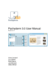
SB-CTL-WP3_D3.4
Grant Agreement n°233994
Figure 4-15 – Example of output from RSA
4.2.2.6 Overall Output
The overall output will be a generated list of countermeasures linked to the risks outlined in
preventative output and also, for existing roads, the accident types/causes identified in the
corrective output. Countermeasures will be selected as the best suited to the road/planned
road based on these inputs made by the end-user.
Linked to the countermeasure types will be the impacts of each suggested countermeasure,
the qualitative benefits of each, and the efficiency/effectiveness of each suggested
countermeasure (in terms of cost benefit, human lives saved, improvements to traffic
environment). The results could be colour-coded in terms of benefit/greatest risk (for
example, using red to show the greatest risk/area requiring most urgent work). A key would
March 2011
Page 44 of 87
CTL – ITRoma – Lough – Mob
SB-CTL-WP3_D3.4
Grant Agreement n°233994
be provided alongside the table to indicate what high/medium/low or the colours mean (see
examples in Table 4-5.)
Table 4-5 Example layout of table for overall output
Suggested
countermeasure
Raised zebra
crossing
Pelican crossing
Safety benefit
Cost-benefit
Qualitative benefits
High reduction in
risk of fatal accident
High (e.g. due to savings
from saved lives & low
installation/maintenance
costs)
Medium
Improved traffic flow
Less fatalities
Medium reduction in
risk of fatal accident
Increased use of
crossing facility in new
location
Key:
High priority
Medium priority
4.2.2.7 Procedure for Monitoring Interventions
In terms of procedures for monitoring interventions, the end-user could be presented with a
form requiring the input of data collected before and after countermeasures have been made,
to compare the earlier site review with a new review. These data will most likely already have
been inputted in previous sections (the accident data, road safety audit data, and so on),
however on this form there will be the facility for end-users to compare two reviews at the
same location and generate output to compare the situation before and after interventions
have been made at the same road location. Details of the data for comparison would include
number and type of accidents, accident risks (to compare if they have increased, decreased
or stayed the same), costs of countermeasures relative to costs of an accident occurring and
maintenance of the countermeasures, severity of accidents occurring before and after the
changes have been made, and so on.
4.2.3
User Interface Design Recommendations for the DSS
In terms of recommendations for the user interface design to maximise usability, the
following are all items for consideration during the design process:
−
Drop down menus that highlight or blank out variables which are / are not relevant
(based on previous selections) to avoid the user having to manually select/deselect
every single variable, and also reduce the risk of the user selecting mutually
incompatible variables.
−
Use of colour to differentiate levels of data input or types of data (e.g. road user data,
vehicle data, environmental data). However, there can be cultural differences in the
use of colour (for example, red is universally used to indicate danger, but in China
also represents good fortune) and also need to take account of the possibility of
colour-blindness. Colour should not be crucial to understanding or navigation within
the system, simply an extra tool to increase ease of use if appropriate.
−
Links to further detail or explanations of terms given could be provided alongside
input boxes if required.
March 2011
Page 45 of 87
CTL – ITRoma – Lough – Mob
SB-CTL-WP3_D3.4
Grant Agreement n°233994
−
Different levels of detail can be used to provide access to the levels of input (and
output) without overwhelming the user by trying to show everything on one screen.
For example, toolbars (where all items are immediately visible), menu items,
submenu items, dialogue boxes (that appear when the user selects an item),
secondary dialogue boxes (requiring selection of a button within a first dialogue box),
and ‘advanced user mode’ functions (requiring the user to select ‘advanced’ options)
are all ways of simplifying the initial presentation of the system but including the
amount of detail that is required for the system to function well.
−
Changes in the state of the system should be made obvious to the user, for example
in shading out options that cannot be selected due to a prior selection.
−
Shortcuts should be provided so that users can navigate, for example, from a sublevel to the top level easily and quickly, to avoid users getting ‘lost’ in the multiple
sub-levels of data input levels.
−
Having access to help menus and ‘undo’ features can increase user confidence when
using the system, allowing them to seek help when needed and also feel secure in
the knowledge that if they make an error they can correct it with minimal disruption.
−
Use of format and/or colour need to be used to differentiate quickly and easily for the
end-user which forms/areas of forms they are required to input data into, and which
indicate outputs.
March 2011
Page 46 of 87
CTL – ITRoma – Lough – Mob
SB-CTL-WP3_D3.4
Grant Agreement n°233994
5. Description of DSS
This section describes the SaferBraIn DSS and its three main modules (i.e. accident data
entry, functions for preventive approach and functions for corrective approach).
5.1
DSS Architecture
The SaferBraIn DSS is composed by three main parts:
−
Accident data entry module.
−
Corrective analysis module.
−
Predictive analysis module.
While the Accident data entry module is a desktop application intended to support the user in
preparing accident database provided by geographic information and VRUs crash pattern
descriptions, both Corrective and Predictive modules are available for analysis activities in a
Web application.
Accident data can be uploaded into the DSS database both from the Accident data entry
module and any other source by using a dedicated data processing module, including a set
of data consistency controls (see Annex V). Users enter accident data manually into the
desktop application, and then need to export the data and import it into the DSS (web-based)
application for analysis. This allows the generation of an accident database (on the desktop)
without needing to be linked to further analysis, but analysis can be conducted as and when
required by exporting/importing the relevant accident data into the DSS for data-processing.
The schema of the DSS architecture is shown in Figure 5-1.
Figure 5-1 - Simplified architecture of SaferBraIn DSS
5.2
Accident data entry module
5.2.1 User interface
This module is desktop based. The database and all necessary features must be installed in
the host computer. The user interface is simple to understand, because it is structured
basically with buttons and drop down list controls.
March 2011
Page 47 of 87
CTL – ITRoma – Lough – Mob
SB-CTL-WP3_D3.4
Grant Agreement n°233994
The application starts by clicking on its icon
On the left side seven buttons are available:
−
Add new accident
−
Browse the list of accident
−
Find an accident by search criteria
−
Open existing accident
−
Export accident data
−
Google maps
−
Exit button
and the main form is shown (Figure 5-2).
Figure 5-2 - Main form
5.2.2 Accident data
Each accident input is composed of three groups of information:
−
Local information concerning date and time, kind of intersection or non-intersection
that the accident occurred at, weather conditions at the time of the accident, kind of
impact, etc.
−
Details about any vehicles involved, with their driver and/or passengers.
−
Details about any pedestrians involved.
While it is possible to manage every kind of accident, this module is specialised in accidents
involving VRUs. This means that the DSS will analyse only accidents with VRUs involved to
find critical situation and to propose countermeasures, but it is possible to store an entire
accident database within the system.
March 2011
Page 48 of 87
CTL – ITRoma – Lough – Mob
SB-CTL-WP3_D3.4
Grant Agreement n°233994
When a bicycle and/or pedestrian is present in the accident, the software recognises this
situation and ask the user to input additional information concerning the scenario and the
actions, distinguishing between bicycle and pedestrian, to find an exact crash pattern code
(Figure 5-3).
Figure 5-3 - Crash pattern selection form
Local data
Information concerning local data and site conditions are entered as well (Figure 5-4).
Information is arranged in tabs by categories. Most are drop-down lists and the user is
required to select one item from each list.
Because geographic information is needed for each accident, users can use map features to
select road elements on a map (if the user can provide latitude and longitude coordinates).
March 2011
Page 49 of 87
CTL – ITRoma – Lough – Mob
SB-CTL-WP3_D3.4
Grant Agreement n°233994
Figure 5-4 - Local data form
Persons and vehicle
Persons and vehicles could be added by clicking on the menu on the top-left side of the
window. An example of the form to input vehicle data is given in Figure 5-5.
March 2011
Page 50 of 87
CTL – ITRoma – Lough – Mob
SB-CTL-WP3_D3.4
Grant Agreement n°233994
Figure 5-5 - Example of Vehicle data form
Export data
To export accident data from the Accident data entry module database to the DSS database
the user must click on the Export button in the Main form (Figure 5-2). A new form appears
(Figure 5-6).
March 2011
Page 51 of 87
CTL – ITRoma – Lough – Mob
SB-CTL-WP3_D3.4
Grant Agreement n°233994
Figure 5-6 - Form to export data
The user must load the data before exporting them. In order to do this, the user must select
the top-left menu in the Main form and set the selection criteria. The list of results is then
shown and the user can select each single accident to be exported (Figure 5-7).
March 2011
Page 52 of 87
CTL – ITRoma – Lough – Mob
SB-CTL-WP3_D3.4
Grant Agreement n°233994
Figure 5-7 - Example of accidents to export
Output files are stored in the selected folders in three separated XML format files:
−
Accident: I_ yyyyMMddhhmm.xml
−
Vehicle: V_ yyyyMMddhhmm.xml
−
Persons: P_yyyyMMddhhmm.xml
Data must be uploaded in the DSS by using the uploading function available. A scheduled
process recognizes the source and imports the data.
5.3
Corrective analysis module
SaferBraIn DSS allows users to create and manage corrective analysis through a specialized
module for Pedestrian and Cyclist Analysis.
5.3.1 Preface
The PCA (Pedestrians and Cyclists Analysis) – Vulnerable Road Users Safety Assessment
is an add-on software module allowing the users to identify the possible actions that can
enhance Vulnerable Road Users safety through the analysis of accidents.
The analysis process will guide the user in studying pedestrian or cyclist accidents rate
features, highlighting where, how and why accidents occur and what can be, in each case,
the most effective countermeasures.
In particular, the PCA module allows the user to:
−
Identify and classify critical elements (links or nodes) of the road network.
−
Identify the type of critical accidents of an analyzed element (link or node).
March 2011
Page 53 of 87
CTL – ITRoma – Lough – Mob
SB-CTL-WP3_D3.4
Grant Agreement n°233994
−
Identify the possible causes contributing to accidents of a road element.
−
Identify the possible countermeasures to eliminate the causes identified.
−
Prepare a report on the analysis.
This chapter is a quick reference guide designed to support users through use of PCA
module.
The following sections describe the methodological approach of the module that the user
needs to know in order to correctly interpret the results, the interface structure, functions and
procedures to be followed to use these functions.
5.3.2 Methodological Approach
Once data have been collected, information relating to pedestrians or cyclists involved in
road accidents is computerised and archived in the database on which the PCA module
performs its processing.
It should be noted that data on road accidents involving pedestrians or cyclists may be
collected using the software PCA management desktop add-in module. Accident data may
also be imported from other sources, according to the requirements for the variables and
data types needed (see Annex V). The SaferBraIn DSS is provided with functions to import
well formed data from external sources in xml format. Using this feature, each accident (with
at least a pedestrian or cyclist involved) is associated with a specific type of accident (“crash
pattern"), allows understanding of the accident dynamics and identification of some possible
causes for the accidents.
The accident causes are related to the dynamics of the events and circumstances in which it
occurred. It is possible to describe events and conditions through the crash pattern, allowing
the user to identify the more likely factors affecting the safety of a site.
Depending on the different issues related to safety that may be encountered on a particular
site, the analysis is differentiated by type of road elements (road sections and intersections)
as well as by type of vulnerable road users (cyclists and pedestrians). This means that the
accident analysis of accidents where pedestrians are involved is conducted separately from
accidents with cyclists involved, but using the same methodology.
It should be noted that to obtain results that are meaningful, the proposed analysis approach
requires a substantial amount of accident data, which may be unavailable for various
reasons.
Depending on the amount of data available, the process of analysis to identify possible
countermeasures can be conducted through two different approaches: the first data analysis
in aggregated and the second in a disaggregated way. Aggregated mode refers to accidents
where not much data about the accident is available, just the location and type of accident,
and can be used for assessment of new roads where road safety audits have been or will be
carried out. The disaggregated mode is where full data for the accident is available, including
information about critical elements and other involvement. The user should not apply the
disaggregated mode analysis in the software if there is an insufficient number of accidents in
the database, otherwise this may generate misleading results. The user can still analyse the
data even when data are not sufficient, according to an approach, implemented in software,
which analyses the accidents in aggregated mode.
Figure 5-8 shows a block diagram representing the process implemented in PCA for the
identification of possible countermeasures for pedestrians and cyclists in the event of
significant (disaggregated) and insignificant (aggregate) data.
March 2011
Page 54 of 87
CTL – ITRoma – Lough – Mob
SB-CTL-WP3_D3.4
Grant Agreement n°233994
Figure 5-8 - Block diagram of PCA analysis process
The users can choose which approach (aggregated or disaggregated) to follow according to
the availability of accident data.
Once the user has selected the type of approach, they must decide on which road elements
to focus the analysis, given the diversity of issues that are usually raised at intersections and
at road sections. "Nodes" or "links" elements may be considered in the analysis process.
Following the approach of disaggregated analysis, the next step is the determination of all
those elements which have submitted an accident percentage rate greater than a calculated
critical value C. C is a ”critical accident frequency“, if an element accident frequency exceeds
this threshold the element should be considered for a more detailed analysis. Different
methods exist in literature for critical accident frequency calculation, in this case by empirical
studies C has been set to the average accident frequency for all elements plus 20%. Once
such ”critical elements“ of the network are identified, these are classified according to the
frequency of those accidents being recorded.
The main critical element to be analyzed is chosen from among the critical elements just
identified (typically the one that has the greater frequency recorded) and then the type/s of
critical accident (crash or critical pattern) can be identified by calculating the ratio between
the number of accidents observed for that crash pattern at that location and the average
number of accidents, related to that crash pattern, occurring at the type of road element
considered. If the ratio is greater than one, then the crash pattern is critical for that node or
link and should be taken into account in the analysis of possible causes. In the case of
multiple critical crash patterns, only one at time will be chosen for the analysis of possible
causes.
Each crash pattern is associated with a number of possible causes, and a range of possible
countermeasures to these causes. Of course, it may not be that all possible causes
associated with a selected crash pattern will be present or relevant for the site in question.
March 2011
Page 55 of 87
CTL – ITRoma – Lough – Mob
SB-CTL-WP3_D3.4
Grant Agreement n°233994
For example, if many collisions were reported in an intersection, one possible cause could be
the presence of vehicles that slow down suddenly to turn right, but the real problem may
actually be due to the frequent crossing of pedestrians. For this level of information the user
needs to know the site or provide an inspection to verify the existence of such causes.
The same is true for the countermeasures. To choose the most appropriate
countermeasures, as well as ensure applicability to the actual site in question, the costs and
benefits associated with each countermeasure are assessed. To give an indication of the
expected benefits, the ability of the countermeasure to reduce the number of accidents is
calculated, given by the estimated value of the effectiveness of the countermeasure and its
confidence interval, which gives an idea of the value of effectiveness provided.
When conducting an aggregated analysis, the process involves an analysis of crash patterns
and possible causes and countermeasures on the whole network. In this case, the user has
to identify the most frequent causes of accidents and analyze the road network through a
road safety audit or road safety inspection. A road safety audit or road safety inspection
consists of an analysis in the field to verify the presence of risk factors identified by means of
the aggregated analysis of accidents. Once the user has identified those elements where
possible causes are associated with the selected crash pattern, the user can determine
appropriate countermeasures.
5.3.3
User interface
The PCA module is a web tool based on Microsoft.net platform. The user interface is the
navigation of dynamic web pages through a web browser. The user interaction is provided by
menus, buttons and other items that allow you to automatically perform the required
operations.
Web forms
There are different layouts designed for the web pages for the forms for detailed information
given by tree-view, grid-view or report pages, or pages with layout to set parameters. There
are different layouts designed for the web pages for the forms for detailed information given
by tree-view, grid-view or report pages, or pages with layout to set parameters.
The web forms within the program are divided into different sections, each of which
performing a different function (see Figure 5-9 and Figure 5-10):
−
The top bar of the form will inform the user about their current location within the
analysis process, the overall state of the project, the type of VRU being analysed, and
the type of aggregation being used. There are also two buttons present to navigate
up and down through the project process and a button to exit the project.
−
A left menu (not always present) to select other functionalities as available.
−
A brief guide explaining the meaning of the form and the action to be done to go on
with the project process.
−
The body of the form shows the results of the operations carried out by the software
at every step. In some cases, the software requires the selection of some elements
among those listed to proceed in the analysis; almost always, the user can request
more details about the elements listed.
−
Buttons allowing navigation through the analysis process and the application of new
actions.
March 2011
Page 56 of 87
CTL – ITRoma – Lough – Mob
SB-CTL-WP3_D3.4
Grant Agreement n°233994
Figure 5-9 - Example of web form in PCA module
Figure 5-10 - Examples of another web form in PCA module
Software objects
The software has a "user friendly" structure, designed to let the user easily perform the
required operations. It is possible to use all the functions with the simple mouse clicking on
the appropriate buttons.
The objects that are present in the web application with which the user interacts are identified
as follows.
Explanatory labels
adjacent boxes.
March 2011
indicate the type of information requested or displayed in the
Page 57 of 87
CTL – ITRoma – Lough – Mob
SB-CTL-WP3_D3.4
Check boxes
Radio buttons
Grant Agreement n°233994
allow the user to enable or disable an option to select one or more items.
allow the selection of a single item.
Information buttons
images.
launch a new browser window that displays information notes and
Command buttons, displayed in text and/or drawings. Using these buttons, the user can
open new web forms or start data processing operations.
Google Earth buttons
opens Google Earth Tool and displays accidents present in the
database, geo-referencing them in the map.
Next buttons
to go on to the next step of the analysis process.
Back buttons
to go back to the previous step of the analysis process.
Stop buttons
to exit the project process.
Launching the tool
To start the PCA module the user must connect with a web browser (e.g. Internet Explorer or
Mozilla Firefox) to the URL of the application, then:
−
Click on the Login command.
−
Enter login credential.
−
Expand the link Road safety assessment of the tree-view menu on the left panel, and
then click on the item PCA – Vulnerable Road Users safety assessment (Figure
5-11).
Figure 5-11 - Menu available after SaferBraIn DSS login
March 2011
Page 58 of 87
CTL – ITRoma – Lough – Mob
SB-CTL-WP3_D3.4
Grant Agreement n°233994
Then the user can enter the form where it is possible to manage PCA analysis projects. The
user can start a new PCA analysis project or open a saved one (listed in the grid-view to see
its details if completed, or to go on with the steps of an incomplete process). If the accident
data have longitude and latitude data included, then the user can display pedestrian or cyclist
accidents in Google Earth (Figure 5-12).
Figure 5-12 - Example of accident data displayed on Google Earth Maps
The grid view has nine columns (Figure 5-13):
−
I column allows for selecting the project;
−
II column contains the ID code of the project;
−
III column is the date of creation of the project;
March 2011
Page 59 of 87
CTL – ITRoma – Lough – Mob
SB-CTL-WP3_D3.4
Grant Agreement n°233994
−
IV column specifies the type of road elements: links or nodes;
−
V column indicates the element name;
−
VI column specifies if the project is dealing with aggregated or disaggregated
elements;
−
VII column displays the level of completeness of the project process;
−
VIII column contains the ID code of the element being assessed;
−
IX column is a link to the package of countermeasures, if already created for the
current project.
Figure 5-13 - Form to manage PCA projects
If the user wants to open a new PCA project, then they click on the New command button to
enter a form where it is possible to choose the main settings of the new PCA project: the
user can define filter criteria to select accidents (timing filter, qualitative filter, geographical
filter) and then save the new project (Figure 5-14).
If the user has chosen to create a new PCA project, the first step is to define all the initial
settings for the project. Choices available for the initial project settings are:
−
VRU type: select among PCA pedestrians or cyclists using the specific radio buttons,
depending on the type of analysis to be performed.
−
Analysis approach: select between aggregated or disaggregated, depending on the
statistical significance of data available.
−
Method of identification of critical elements: At the moment the only item available is
the “Method of Annual Frequency”, then you can choose between “Average + Growth
of 20%” or “Average + Standard Deviation”.
−
Type of road elements: select between nodes or links.
March 2011
Page 60 of 87
CTL – ITRoma – Lough – Mob
SB-CTL-WP3_D3.4
Grant Agreement n°233994
Figure 5-14 - Web form for initial PCA project settings
The entire review process will guide the user through eight web forms for the disaggregated
analysis or seven web forms in the aggregated analysis: the transition from one step to the
next is done through some simple selections.
In detail, the eight windows show:
−
Settings: contains selection criteria for the type of data elements, type of road
network, type of VRU, method for identification of critical elements.
−
Road elements (only disaggregated analysis): calculates and sorts the elements of
the network for accident frequency (number of accidents during the period considered
in the case of nodes and number of accidents per km in case of links).
−
Crash Pattern: listing and classifying accidents crash pattern (type of accident) at a
selected element site (disaggregated case) or for the whole area (aggregated case).
In this form it is possible to display detailed information about the selected crash
pattern.
−
Possible causes: listing causes associated with the selected crash pattern. This web
form is where it is possible to select possible causes applicable to the selected crash
pattern.
−
Possible countermeasures: listing the countermeasures associated with the
selected causes and related to the selected crash patter.
March 2011
Page 61 of 87
CTL – ITRoma – Lough – Mob
SB-CTL-WP3_D3.4
Grant Agreement n°233994
−
Countermeasures Package: listing of countermeasures and package of
countermeasures associated with the selected causes and related to the selected
crash pattern.
−
Economic situation: section for entering financial data for the calculation of the
economic situation. It is possible to set economic data for the countermeasures
chosen to be examined. The user can select between cost/benefit or
cost/effectiveness analysis and set the interest rate.
−
Summary Report: the report of the analysis performed in the current PCA project.
Settings
The Settings form allows you to select, via radio buttons, to set the approach and the type of
road elements (links or nodes) on which to make the analysis process.
The user can click on aggregated or non-aggregated mode, depending on the type of data
within the database.
The user can click on links or nodes to select the type of elements road on which to do the
analysis, and finally in clicking
frequency of accidents.
to start the process and continue to calculate the
Statistical significance of data and type of road elements
The analysis process is related to the amount and significance of the accident data available.
In general at least a three years sample of data is needed for the analysis, but the sample
could be still not sufficient. For the assessment of the data sample, a significance test based
on the comparison with the expected number of accidents could be carried out.
Two different analytical approaches are provided (aggregated and non-aggregated),
depending on the statistical significance of the accident data available. If data are significant,
then a non-aggregated approach can be followed.
The assessment of statistical significance can be done qualitatively by the analyst (three
years data available) or by an appropriate test of significance.
Type of Analysis Approach
The disaggregated analysis approach suggests that accident data are statistically significant.
The aim is to identify the most effective countermeasures to be implemented on the most
risky elements of the road network. This methodology, in particular, includes the study of
crash patterns and possible causes and countermeasures at local points of the network,
making a disaggregated data analysis.
In the aggregated analysis approach, accident data are analyzed as a whole. This approach
is then followed in the case of data that are not statistically significant. The aim is to identify
possible causes of accidents to be verified in the field through a proper analysis of road
safety audit or road safety inspection, and/or analyze the roadway database where the
characteristics of each road have been computerized.
Type of Road Elements
The second step of the analysis process is the choice of the network elements to consider:
links or nodes.
The road network has been divided into links and nodes. In particular, the network nodes are
defined as intersections of roads, those points where two or more roads intersect. Links
mean, instead, road sections between two singular points, usually between two intersections.
The selection of settings
March 2011
Page 62 of 87
CTL – ITRoma – Lough – Mob
SB-CTL-WP3_D3.4
Grant Agreement n°233994
The Settings form allows the user to select, via radio buttons, the approach and the type of
road elements: links or nodes on which make the analysis process.
As before, the user can click on aggregated or non-aggregated, depending on the type of
data within the database, and
click on links or nodes to select the type of element road on which to do the analysis, and
then click
to start the process and continue to calculate the frequency of accidents.
If the user has selected the disaggregated analysis approach, a new window will open where
the criterion by which the software will proceed with the determination of the critical road
elements can be defined. This is the definition of the threshold above which a road element
is considered critical. The threshold is defined as the average number of accidents recorded
on the selected type of element, increased by a percentage value referring to the average.
This value is set by default to 20% and should only be changed with extreme caution.
Road elements
The user should check “Show only the critical elements” if they want to display only the
critical elements, and leave it unchecked if they want to display all the elements.
The web form contains a list of road elements, nodes or links, sorted by frequency of
accidents for each network element. In this window the user can select the road element to
be analysed in detail, based on the level of accidents reported in that area.
The user can access the Road Elements window only if they have previously selected the
option of disaggregated analysis approach in the Settings window.
Once the user has entered the Road Elements Form, the software classifies nodes or links
for frequency (nodes) or km rate (links).
A summary grid is generated and provided, with global statistics related to road elements
according to the initial settings entered in the previous web forms.
Another grid-view with eleven columns will then be displayed: each row represents a node or
a link. The first column allows the selection of the node or the link to be examined; the other
columns list the relevant characteristics for the element: the number of accidents with injuries
or no injuries, the number of fatal accidents and so on.
The user can then click to select the road element on which to start the analysis of accidents,
and then click
to continue to identify crash patterns.
Crash Pattern
The Crash Pattern Form lists the types of accidents recorded in an element or in the entire
area, depending on whether the data analysis type is aggregated or disaggregated.
In the aggregate analysis approach, the software classifies crash pattern using the calculated
frequency, indicating the percentage of total recorded accidents.
The crash patterns are displayed in a grid-view. The first column allows the selection of the
crash pattern to be examined. Using the information button located in the last column the
user can get a description and a graphical representation of the specific crash pattern (Figure
5-15 and Figure 5-16). The other columns contain the description of the specific crash
pattern, the frequency (number of accidents recorded in a crash pattern), the percentage of
the total, a priority index calculated as the ratio between local frequency and total percentage
of the area.
March 2011
Page 63 of 87
CTL – ITRoma – Lough – Mob
SB-CTL-WP3_D3.4
The user should click
Grant Agreement n°233994
to view a description of the individual crash pattern, click
select the crash pattern to analyse, and then click
countermeasures associated.
to
to continue to identify the causes and
Figure 5-15 - Crash pattern window, for disaggregated analysis approach
Figure 5-16 - Crash Pattern description
In the case of the disaggregated analysis approach the crash patterns are initially classified
by recorded frequency as in the case of aggregate analysis approach. The results are
presented in a grid-view with the same columns. To let each country or region (e.g. Europe,
March 2011
Page 64 of 87
CTL – ITRoma – Lough – Mob
SB-CTL-WP3_D3.4
Grant Agreement n°233994
India, Brazil) load different possible causes and relative countermeasures, this is at present a
dropdown list box.
Possible causes
In the Possible Causes window (Figure 5-17), a series of information concerning the causes
that could be related to the accidents that have occurred at the current site are displayed. It
is possible to add a comment to each possible cause and save it in the database as linked to
the PCA project. The user also has the option to print a report of possible causes check list.
Figure 5-17 - Example of Possible Causes Form
The user can then click
the next step.
to select the relative possible causes and then click
to go to
Possible countermeasures
In the Possible Countermeasures Window a series of information concerning the
countermeasures associated with the selected causes and related to the selected crash
pattern are displayed. It is possible to add a comment to each possible countermeasure and
save it in the database as linked to the PCA project (Figure 5-18).
March 2011
Page 65 of 87
CTL – ITRoma – Lough – Mob
SB-CTL-WP3_D3.4
Grant Agreement n°233994
Figure 5-18 - Example of Possible Countermeasures Form
After this, the user can click
to select the countermeasures relative to the possible causes
already selected for the current crash pattern.
Countermeasures Package
In the Countermeasures Packages form, it is possible to build a package of
countermeasures, by selecting more than one measure from the countermeasures chosen at
the previous step (Figure 5-19).
March 2011
Page 66 of 87
CTL – ITRoma – Lough – Mob
SB-CTL-WP3_D3.4
Grant Agreement n°233994
Figure 5-19 - Example of Countermeasures Package Form
The user can then click
on the countermeasures they want to add to the package, then
click on the button “Update package”, and then click
to go on with the analysis.
Economic Situation
In the Economic Situation Form (Figure 5-20), the user has to select the countermeasures to
be evaluated economically. To perform the economic analysis, the user has to input the
expected costs for the planned countermeasures, and then click on the Update button. The
user then has to choose between cost/benefit or cost/effectiveness analysis, input the
interest rate, and then click
to proceed with the analysis. The countermeasure package
will then close and a button to open a summary report will be displayed (Figure 5-21).
March 2011
Page 67 of 87
CTL – ITRoma – Lough – Mob
SB-CTL-WP3_D3.4
Grant Agreement n°233994
Figure 5-20 - Example of Economics Situation Form
Figure 5-21 - Example of completed economic analysis for a selected countermeasures
package
Summary report
This is the final form that shows the summary report of the PCA project that has been
completed. An example is given in Figure 5-22.
March 2011
Page 68 of 87
CTL – ITRoma – Lough – Mob
SB-CTL-WP3_D3.4
Grant Agreement n°233994
Figure 5-22 - Example of summary report
The project is then saved into the database, and it is possible to retrieve data and show the
analysis at a later date, whenever required.
5.4
Accident reports
As a support to the corrective analysis, a series of graphic or tabular reports are available in
SaferBraIn DSS. These reports are built in real time using data actually present in the
accident database.
A list of possible reports available is proposed below:
−
Accidents by area.
−
Report based on road names.
−
Accidents by month.
−
Accidents by type.
−
Accidents per year.
−
Accidents by severity.
Graphs can then be generated to illustrate the problems and/or risks to project partners and
other interested people. Figure 5-23 gives an example of a graphic generated to show
‘accidents by severity’
March 2011
Page 69 of 87
CTL – ITRoma – Lough – Mob
SB-CTL-WP3_D3.4
Grant Agreement n°233994
Figure 5-23 - Example of a report "Accidents by severity”
5.5
Predictive analysis module
The SaferBraIn DSS also allows users to create and manage predictive analysis through a
specialised module for Road Safety Audit and Inspection.
5.5.1 Road safety audit/inspection projects
After login, the user of the SaferBraIn DSS can create their own analysis project by inputting
information through a form.
The user sets the kind of project by selecting the project type:
−
Planning Stage.
−
Preliminary Stage.
−
Final Design Stage.
−
Work Zone Traffic Scheme.
−
Pre-Opening Stage.
−
Existing Roads.
−
Land Use Development Proposals.
−
Pedestrian.
March 2011
Page 70 of 87
CTL – ITRoma – Lough – Mob
SB-CTL-WP3_D3.4
−
Grant Agreement n°233994
Cyclist.
In the list above, the first five elements correspond to an audit project, the rest of the list refer
to inspection projects.
To complete the analysis project, the user opens the project form (Figure 5-24).
Figure 5-24 - Road safety project details
Project details/documentation
To add details and documentation (images, PDF files, Autocad files, etc) the user can upload
files directly from their PC. It also possible to input geographic information to the document
by giving latitude and longitude coordinates for the location that the file is related to. An
example of the project details/documentation upload form is given in Figure 5-25.
March 2011
Page 71 of 87
CTL – ITRoma – Lough – Mob
SB-CTL-WP3_D3.4
Grant Agreement n°233994
Figure 5-25 - RS project details/documentation
Project characteristics
The project characteristics are the list of attributes and settings that will define the list of
checklist elements to be investigated.
While the system allows users to use different checklist sources, the characteristics needed
for the checklists available in the DSS are:
−
Pedestrian (Y/N)
−
Land Use Development Proposal part of (Y/N)
−
Adjacent Land Use
−
Design Speed
−
Opposite Flow Separation
−
Service Function
−
Terrain
−
Climatic Conditions
An example of the project characteristics selection form is given in Figure 5-26.
March 2011
Page 72 of 87
CTL – ITRoma – Lough – Mob
SB-CTL-WP3_D3.4
Grant Agreement n°233994
Figure 5-26 - Project characteristics
Project team
The user can specify the list of persons involved in the analysis by adding their names in the
project team list.
Project checklist
To add an issue to the project checklist (Figure 5-27), the user must select a combination of
one checklist item and a location.
While the checklist items are automatically selected by project characteristics, locations can
be added to the project by the user depending on their investigations.
Figure 5-27 - Project checklist
March 2011
Page 73 of 87
CTL – ITRoma – Lough – Mob
SB-CTL-WP3_D3.4
Grant Agreement n°233994
For each issue it is possible to set information concerning safety evaluation based on four
aspects:
−
Exposure.
−
Probability.
−
Consequence.
−
Safety risk (a combination of above aspects).
It is also possible to save a map link by copying/pasting an URL from Google Maps site.
Project report
To generate and print a report with the project summary, the user can click on the “Show
report” button. Figure 5-28 displays an example report.
Figure 5-28 – Example of project report
March 2011
Page 74 of 87
CTL – ITRoma – Lough – Mob
SB-CTL-WP3_D3.4
Grant Agreement n°233994
6. Conclusions
The DSS of SaferBraIn is a flexible tool that can be used by decision-makers and
practitioners to analyse safety conditions of Vulnerable Road Users (with specific reference
to cyclists and pedestrians). The tool can be used both for taking decisions in a preventive or
in a corrective phase.
The preventive approach relates with cases where accident data are not available, making
impossible the choice of treatments based on accident analysis. This case typically refers to
verification of safety conditions of infrastructure designs or on existing roads without accident
data. Thus, the DSS supports the execution of Road Safety Audits or Inspections, providing
specific check-lists for safety of cyclists and pedestrians and tools for reporting about
recommendations proposed.
The corrective approach relates with analysis based on accident data. In this case the DSS,
basing on reliable data, provides a support for defining the accident causes and the possible
countermeasures / treatments that can be adopted. The corrective approach is usually used
to make safer infrastructures where several accidents occur. For this approach, the DSS also
supports the identification of more reliable treatments basing on expected impacts and costs.
In all cases, the tool has been developed in order to be adapted to the local conditions of
India and Brazil and to be also easily adaptable to other situations or regions.
SaferBraIn DSS is fully in line with the indications of the Directive 2008/96/EC on road
infrastructure safety management. Especially, the tool provides support concerning road
safety impact assessment for infrastructure projects (Article 3), road safety audits for
infrastructure projects (Article 4) and safety inspections (Article 6).
The DSS aims to provide help to technicians and decision-makers to carry out accident
analysis or road safety audits/inspections. Its use requires a knowledge and experience
about road safety issues, especially necessary for selecting the most appropriate
countermeasures or to produce recommendations for road safety audits.
SaferBraIn DSS has been developed as a web application accessible for free from the
project web site (www.saferbrain.eu), together with the user guide.
March 2011
Page 75 of 87
CTL – ITRoma – Lough – Mob
SB-CTL-WP3_D3.4
Grant Agreement n°233994
7. References
AA.VV. (2008) SFINGE Modulo Analisi PCA – Software user manual – I.T. Ingegneria dei
Trasporti Srl
Cuerden, R., Pittman, M., Dodson, E. And Hill, J. (2008) The UK On The Spot Accident Data
Collection Study – Phase II Report. UK Department for Transport, Road Safety Research
Report
No.
73.
http://www.dft.gov.uk/pgr/roadsafety/research/rsrr/theme5/onthespotaccident.pdf
(25th
October 2010)
UK Highway Agency (2007). Road Restraints Risk Assessment Process (RRRAP).
http://www.highways.gov.uk/business/12081.aspx (25th October 2010)
UK Highways Agency (2006). Requirement for Road Restraint Systems TD 19/06. Design
Manual for Roads and Bridges.
http://www.standardsforhighways.co.uk/dmrb/vol2/section2/td1906.pdf (25th October 2010)
UK Highways Agency (2003). Road Safety Audit. HD 19/03. Design Manual for Roads and
Bridges.
http://www.standardsforhighways.co.uk/dmrb/vol5/section2/hd1903.pdf (25th October 2010)
UK Highways Agency (2005). Non-motorised User Audits. HD 42/05. Design Manual for
Roads and Bridges.
http://www.standardsforhighways.co.uk/dmrb/vol5/section2/hd4205.pdf (25th october 2010)
UK Department for Transport (2004). STATS20: Instructions for the Completion of Road
Accident Reports. http://www.stats19.org.uk/html/stats_20_notes.html (14th October 2010)
Naing, C. et al. (2005). TRACE Deliverable 5.2 - Which Factors and Situations for Human
Function Failures? Developing Grids for Accident Causation Analysis. EC TRACE Project
Report.
User interface design http://en.wikipedia.org/wiki/User_interface_design (18th October 2010)
For User Interface, also refer to:
http://www.usernomics.com/user-interface-design.html (18th October 2010)
http://www.sylvantech.com/~talin/projects/ui_design.html (18th October 2010)
March 2011
Page 76 of 87
CTL – ITRoma – Lough – Mob
SB-CTL-WP3_D3.4
Grant Agreement n°233994
8. Annex I: Collision Types Matrix used in the UK OTS Study
Source: Cuerden et al., 2008
March 2011
Page 77 of 87
CTL – ITRoma – Lough – Mob
SB-CTL-WP3_D3.4
Grant Agreement n°233994
9. Annex II: Pre-Accident Driving Situations Developed in TRACE
Level 1
Going ahead
Level 2
A. Stabilised Situation
Going ahead on a straight road
Going ahead on a left bend
Going ahead on a right bend
B. Intersection
Approaching a 'give way' intersection
Approaching a 'stop' intersection
Approaching a 'traffic signal' intersection
Approaching intersection where road user has right of way
Stopped at a 'give way' intersection
Stopped at a 'stop' intersection
Stopped at a 'traffic signal' intersection
Stopped in road/ turning lane waiting to turn
Going straight on at a 'give-way' intersection
Going straight on at a 'stop' intersection
Going straight on at a 'traffic signal' intersection
Crossing intersection where road user has right of way
Travelling on roundabout (not turning on/off)
Travelling on slip-road (not turning on/off)
Turning across traffic at a 'give-way' intersection
Turning across traffic at a 'stop' intersection
Turning across traffic at a 'traffic signal' intersection
Turning across traffic from main road into side road
Turning away from traffic at a 'give-way' intersection
Turning away from traffic at a 'stop' intersection
Turning away from traffic at a 'traffic signal' intersection
Turning away from traffic from main road into side road
On approach
Stopped
Going ahead
Turning
C. Manoeuvre
Overtaking stationary vehicle on left
Overtaking stationary vehicle on right
Overtaking moving vehicle on left
Overtaking moving vehicle on right
Moved into lane on left (NOT overtaking)
Moved into lane on right (NOT overtaking)
Stopping (not at junction)
Parking (roadside)
Starting (not at junction)
Leaving parking space (roadside)
Turning across traffic from main road into private drive
Turning away from traffic from main road into private drive
Turning across traffic out of private drive
Turning away from traffic out of private drive
Reversing
U-turn
Driving in wrong direction (e.g. down a one-way road)
Overtaking
Changing lane
Slowing
Starting
Turning (not at intersection)
Reversing
U-turn
In wrong direction
D. Other
Parked
Stopped in traffic queue
Pedestrian crossing
Railway crossing
Parked
Stopped in traffic queue
Approaching pedestrian crossing
Stopped at pedestrian crossing
Approaching railway crossing
Stopped at railway crossing
Source: Naing et al., 2005
March 2011
Page 78 of 87
CTL – ITRoma – Lough – Mob
SB-CTL-WP3_D3.4
Grant Agreement n°233994
10.
Annex III: Grid of Contributory Factors Developed in
TRACE
Human Factors
Descriptive
1. Physical/
Physiological
2. Psychophysiological
condition
A. User State
3. Internal
conditioning of
performed task
Generic
Pre-existing impairment
Substances taken alcohol
Substances taken - drugs
Emotional
Fatigue
In a hurry
Right of way status
Excessive confidence
Identification of
potential risk
Driving
Route
Vehicle
1. Little/None
Environment
Driving
Route
B. Experience
2. Overexperienced
Vehicle
Environment
Distraction outside
vehicle*
1. Conflicting
(Distraction)
Distraction within
vehicle*
C. Behaviour
Distraction within user*
Speed
Vehicle positioning
Traffic control
2. Risk taking
March 2011
In-depth Examples
Heart condition/Epilepsy/Other brain condition/Respiratory
condition/Blood condition/Other condition
Hearing/Visual/Physical disability/Other impairment
Above ‘legal’ limit/
Below ‘legal’ limit
Illegal drugs/
Correctly used medication/
Misused medication
Upset/Angry/Anxious/Happy/Other emotion
Physical/Mental
In a hurry
Rigid attachment to the right of way status
Excessive confidence in signs given to others
Identification of potential risk about only part of the situation
Medical condition
‘Eccentric’ motives
Learner/New driver/Infrequent driver/Other
New route/Road type/New road/Road feature/Driving on the
left/Driving on the right/Other
New vehicle/
Transmission type/
Left hand drive vehicle/
Right hand drive vehicle/
Other vehicle feature
Night driving/City driving/Country driving/Driving in snow/Driving
in fog/Driving in wet or flood/Driving in ice/Other
Change in driving rules/Other
Route in general/Road type/New road/Road feature/Other
New vehicle/
Transmission type/Other vehicle feature
Night driving/City driving/Country driving/Driving in snow/Driving
in fog/Driving in wet or flood/Driving in ice/other
Police/Animal in road/
Sunlight or sunset/
People in roadway/
Crash scene/Other perceived danger/Road construction/ Searching for
directional information/
Unspecified outside distraction
Adjusting radio/
Adjusting cassette/
Adjusting CD/
Other occupant/
Moving object in vehicle/
sing or viewing device integral to vehicle/
Using other device brought into vehicle/
Adjusting climate controls/
Eating/Drinking/
Cell phone/
Smoking/
Looking inside vehicle/
Reaching for object/
Unspecified inside distraction
Lost in thought/
Medical problem
Illegal/Legal but inappropriate/Erratic/Other
In front/Lateral/Other
Signs disobeyed/Signals disobeyed /Markings disobeyed/Other
Testing a vehicle/Thrill-seeking/Competing/’Stunt’/Unspecified
eccentric motives
Page 79 of 87
CTL – ITRoma – Lough – Mob
SB-CTL-WP3_D3.4
Grant Agreement n°233994
Road (Environment) Factors
Descriptive
A. Road
Condition
Generic
In-depth examples
Contaminants: Wet/Flood/Snow
Contaminants: Ice/Frost
Contaminants: Oil/Diesel
Contaminants: Sand/Gravel/Mud
Surface defects
Surface type
Bend(s)
Slope(s)
Wet/Flood/Snow
Ice/Frost
Oil/Diesel
Sand/Gravel/Mud
Potholes/Cracks/Bumps
Asphalt/Concrete/Untreated/Cobbles /Brick/Other
Left/Right/Wide/Tight/Multiple bends
Decline/Incline/Multiple slopes
Wide/Narrow/Single lane/Multiple lanes/Change in
width
Left/Right
Road hump/Speed table/Throttle/Chicane
Roadworks/Other
Misleading/Complex
Bend in road/Straight road/Gradient/Wide
road/Continuity effect
Smooth/Erratic
High/Low/Stationary
Low/High
Absence of clues to manoeuvre
Road width
B. Road
Geometry
Adverse camber
Traffic calming
Temporary road layout
Misleading/complex road layout
Speed-inciting layout
C. Traffic
Condition
Flow
Speed
Density
Other road user(s) : Absence of clues to
manoeuvre
Other road user(s) : Ambiguity of clues to
manoeuvre
Other road user(s) : Atypical manoeuvres
Being drawn into manoeuvre
D. Visibility
Impaired
Road lighting
Vehicle lighting
Day/night
Sun glare
Weather
Smoke
Terrain profile
Other vehicle(s)
Roadside objects
Traffic signs/signals - Insufficient
Traffic signs/signals – Maintenance
Traffic signs/signals – Unexpected
Traffic signs/signals – Inappropriate
E. Traffic
Guidance
Road markings (visual/tactile) - Insufficient
Road markings (visual/tactile) - Maintenance
Road markings (visual/tactile) – Unexpected
Road markings (visual/tactile) - Inappropriate
F. Other
Environmental
March 2011
Earlier collision
Pedestrian in road
Page 80 of 87
Ambiguity of clues to manoeuvre
Atypical manoeuvres
Passenger/Vehicle ahead/Vehicle
behind/Pedestrian/Cyclist
Type/Colour/Intensity/No lighting
Type/Colour/Beam type/No lighting
Daylight/Darkness/Dusk/Dawn
Direct from sun/Reflection from wet road
Rain/Fog or mist/Snow/Hail
Vehicle/Nearby fire/Other
Bend/Slope/Side slope(s)/Other
High vehicle/Wide vehicle/Parked vehicle/Vehicle
stopped in traffic/Other
Overhanging tree(s)/ Overhanging
shrubbery/Sign(s)/Bridge
structures/Barrier(s)/Wall(s)/Boundary fence(s)/Other
Signs present but insufficient/Signals present but
insufficient/Signs absent/Signals absent/Other
Signs damaged/Signals damaged/Signs poorly
maintained/Signals poorly maintained/Signs positioned
incorrectly/Signals positioned incorrectly/Other
Signs replaced/Signals replaced/Signs new/Signals
new/Other
Signs inappropriate/Signals inappropriate/Signs
confusing/Signals confusing /Other
Visual markings present but insufficient/Tactile
markings present but insufficient/Visual markings
absent/Tactile markings absent
Visual markings damaged/ Tactile markings damaged/
Visual markings poorly maintained/ Tactile markings
poorly maintained/ Visual markings positioned
incorrectly/ Tactile markings positioned
incorrectly/Other
Visual markings replaced/ Tactile markings replaced/
Visual markings new/ Tactile markings new/Other
Visual markings inappropriate/
Tactile markings inappropriate/
Visual markings confusing/
Tactile markings confusing /Other
Vehicle(s)/Debris/Other
Adult/Child/Other
CTL – ITRoma – Lough – Mob
SB-CTL-WP3_D3.4
Grant Agreement n°233994
Descriptive
Factors
Generic
In-depth examples
Fire in road/roadside
Level crossing
Animal in road
Other obstacle(s) in road
Road works
High wind
Car in Road/Car in Roadside/Other in Road/Other in
roadside
Controlled/Uncontrolled
Dog/Cat/Horse/Cow(s)/Pig(s)/Sheep/
Deer/Rabbit/Badger(s)/Fox(es)/Bird(s)/ Reptile(s)/Other
animal(s)
Vehicle part/Dead animal/Discarded vehicle load/Other
Major/Minor/Other
Gale force/Storm Force/Hurricane force/Other
Source: Naing et al., 2005
March 2011
Page 81 of 87
CTL – ITRoma – Lough – Mob
SB-CTL-WP3_D3.4
11.
Grant Agreement n°233994
Annex IV: STATS19 Contributory Factors Matrix
Source: Dft, 2004
March 2011
Page 82 of 87
CTL – ITRoma – Lough – Mob
SB-CTL-WP3_D3.4
Grant Agreement n°233994
12.
Annex V: DSS requirements about the variables and data
type
Preface
SaferBraIn DSS is composed by three different main parts:
−
Accident data entry module.
−
Corrective analysis module.
−
Predictive analysis module.
Accident data can be uploaded into DSS database both from accident data entry module and
any other source by using a specialized data processing module, which include a set of data
consistency controls.
This document provides information on the entities that make up the DSS database for Road
Safety and their sources in order to guide you through the process of maintenance and
updating.
The document is divided into several sections for each type of data in the database
management system for data and accident data on the graph and road signs will be provided
on the source and the transfer process, decoding may be present on the tables and other
necessary information.
The types of data are:
−
Details of road accidents.
−
Graph of the road network.
For each type will describe the content, format and transfer mode.
The specifications for the data transfer format was established on the basis of accords with
the SaferBraIn Project’s partners that coordinates the implementation of the information
system, any changes are possible but may require the revision of part or all of the loading
process.
The information system using RDBMS as a solution for archiving and data management
Microsoft SQL Server 2005. In relation to the processes of data acquisition, have been
developed routines that use stored procedures in SQL Server 2005 to automate the
processes themselves.
The accidents data must be related to the area of the entity that manages the information
system for road safety and to a single road element – segment or junction.
The knowledge of the source of the data is essential to the right acquisition procedures and
the data check. If the system find presence of an inconsistency in the data, it is necessary to
identify the source for the verification activities.
For these reasons, every partner that provides and delivery data should follow certain
procedures before sending the data, to allow traceability.
The geo-referenced database of road accidents contains information relating to accidents on
the area.
March 2011
Page 83 of 87
CTL – ITRoma – Lough – Mob
SB-CTL-WP3_D3.4
Grant Agreement n°233994
The database has been organized according to a relational data model, whose description is
made through the Entity-Relationship model (ER), which is used to describe the context.
According to this model, the universe is described in terms of entities (representing classes
of items that have common properties), relationships (represented by logical links between
two or more entities) and attributes (describing the properties of entities).
Creation of accident database
The database can be created according to the following two modalities.
Use of Sfinge®
The accidents can be uploaded one by one from the modules on paper by mean of the
interface of Sfinge® that allows to geo-reference the data and to assign the Crash Pattern
code for PCA.
At the end of the insertion it is possible to generate the data to be sent to the DSS according
to the foreseen format (see section Data Transmission).
Using Sfinge® requires the availability of a graph of the road network for the area where the
accidents are available.
Self-made database (Excel, Access, ...)
The data can be managed autonomously in format desired.
In this case it is necessary to foreseen all the fields required by the procedure for the data
transmission (see section Data Transmission) and the Crash Pattern of PCA has to be
defined for each accident with pedestrians and/or cyclists involved (see section Procedure
for assigning CP).
Procedure for assigning CP
For each accident with pedestrians and/or cyclists involved it is necessary to provide a code
to identify the specific Crash Pattern used by the PCA system.
The Crash Pattern code for the accident can be obtained answering to a sequence of
questions related with the type and modality of the event that can be deduced from the
accident report or from the data available.
If Sfinge® is used, the sequence is available in the software (see Figure below).
If a self-made database is used, a graphic schema is available guiding to the Crash Pattern
code to be assigned.
March 2011
Page 84 of 87
CTL – ITRoma – Lough – Mob
SB-CTL-WP3_D3.4
Grant Agreement n°233994
Crash pattern selection form
Data Transmission
Data must be uploaded into DSS by using upload function available. A scheduled process
recognizes the source and provides to import data.
The data have to be sent in the XML format.
The data have to be provided in three file, one for each entity:
−
Accident
−
Vehicle
−
Person
The file must have a name allowing to the system to recognise the source and the content.
The name foreseen are:
−
I_AreaCode_Timestamp.xml
−
V_AreaCode_Timestamp.xml
−
P_AreaCode_Timestamp.xml
Where:
−
I: accidents
−
V: vehicules
−
P: persons
−
AreaCode: code of the data source or of the territory where the accidents have been
recorded
−
Timestamp: date/hour of preparation of the data
March 2011
Page 85 of 87
CTL – ITRoma – Lough – Mob
SB-CTL-WP3_D3.4
Grant Agreement n°233994
While it is mandatory to send the file I_AreaCode_Timestamp.xml for corrective analysis,
also the others are necessary for a more complete analysis.
List of required data
Minimum content of the file related with the accident data (mandatory)
Information
Note
Type of data
Mandatory
Univocal identifier of accident
in the system source of data
Used to avoid to import two time
the same accident
Integer positive with ten
numbers
Y
Code of the data source or of
the territory where the accidents
have been recorded
Univocal identifier of the road
section
Univocal identifier of the
eventual second section
Used to avoid to import two time
the same accident (AreaCode)
Alphanumeric with six
numbers
Y
Used to distinguish the road
sections
Used to distinguish the road
sections
Integer positive
Y
Y
Univocal
junction
Used to distinguish the road
junctions
Integer positive (only for
accidents
to
intersections)
Integer positive (only for
accidents
to
intersections)
Three possible values:
- With dead
- With injured
- Without injured
Integer > 0 (not admitted
accidents
without
vehicles)
Integer positive
Integer positive
Y
Integer positive
Y
Integer positive
Y
Integer positive
Y
Integer positive
Y
Integer positive
Y
Integer positive
Y
Integer positive
Y
YYYYMMDD
N
HH:MM
N
Text
N
Text (only for accidents
at road intersections)
N
identifier
of
the
Accident severity
Used in analysis to distinguish
fatal, with injuries and without
injuries accidents
Total number of vehicles
involved in the accident
Used to avoid to import two time
the same accident and for the
reports
Used to avoid to import two time
the same accident and for the
reports
Used to avoid to import two time
the same accident and for the
reports
Used for economic calculation
B/C
Used for economic calculation
B/C
Used for economic calculation
B/C
Used for economic calculation
B/C
Used for economic calculation
B/C
Used for economic calculation
B/C
Used for economic calculation
B/C
Used to generate report based on
periods and to filter the data to be
analysed basing on a period
Used to generate report based on
time frames
Used to identify the road in the
report and in the analysis
Used to identify the road in the
report and in the analysis
Total number of pedestrians
involved in the accident
Total number of cyclists
involved in the accident
Total number of persons died
Total number of persons injured
Total number of persons unhurt
Number of pedestrians died
Number of pedestrians injured
Number of cyclists died
Number of cyclists injured
Date of accident
Hour of accident
Name of the first road
Name of the second road
March 2011
Page 86 of 87
Y
Y
Y
Y
CTL – ITRoma – Lough – Mob
SB-CTL-WP3_D3.4
Grant Agreement n°233994
Information
Note
Type of data
Mandatory
Type of accident
Used in the report to aggregate the
accidents by type
Code of PCA type of accident
Text
N
Integer positive
>1000 and <2000 with
pedestrians
>2000 and <3000 with
cyclists
=0 for others
Y
Crash Pattern
Minimum content of the file related to vehicles (optional)
Information
Note
Type of data
Mandatory
Univocal identifier of the vehicle in
the system source of data
Univocal identifier of the accident in
the system source of data
Sequential number of the vehicle
Used to identify the record
Integer positive with
ten numbers
Integer positive with
ten numbers
Integer positive > 0
Y
Text
Integer positive
N
Y
Text
Y
Damages
Total persons transported
Type of vehicle
Used to identify the record
Used to sort the upload of
vehicles
Type of damages
Total number of persons on
board (driver excluded)
Type of vehicle involved (car,
bicycle, …)
Y
N
Minimum content of the file related to persons (optional)
Information
Note
Type of data
Mand.
Univocal identifier of the
person in the system source of
data
Univocal identifier of the
vehicle in the system source of
data
Univocal identifier of the
accident in the system source
of data
Number of the passenger inside
the vehicle
Type of person
Gender of the person
Nature and type of the
consequences for the person
Used to identify the record in the database
Integer positive
with ten numbers
Y
Used to identify the record in the database (only
for persons transported on board of the vehicles
involved)
Used to identify the record in the database
Integer positive
with ten numbers
Y
Integer positive
with ten numbers
Y
Used to sort the upload of persons
Integer
>0
Text
Text
Text
N
Type of person (Driver, passenger, pedestrian)
Gender of the person (M/F)
Nature and tyoe of the consequences for the
person
positive
Y
N
N
Road network database
The road network representation must be acquired before accident data uploading.
The road network can be submitted in ESRI Shape format once at the beginning.
This road representation must be the same as the one used during the accident georeferencing phase. Unique identifier of the road segment, unique identifier of the eventual
second segment and unique identifier of the junction are considered by this representation.
If Sfinge® is used to geo-reference the accidents, the road network must be loaded into this
software.
March 2011
Page 87 of 87
CTL – ITRoma – Lough – Mob