1
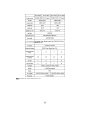
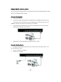
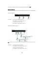
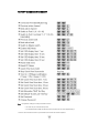
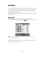
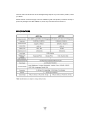
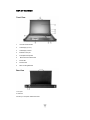
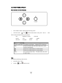
8/16 Port LCD KVM Switch
JKP115-801e/117-801e
JKP115-1601e/117-1601e
LCD Control Console
JKP115e/117e
User Manual
JKP115-801e/117-801e & JKP115-1601e/117-1601e LCD KVM SWITCH
MANUAL CONVENTIONS...........................................................................P1
TECHNICAL SUPPORT......................................................................................P1
INTRODUCTION.................................................................................P1
APPLICATIONS............................................................................P2
OVERVIEW................................................................................P2
FEATURES ...............................................................................P3
PACKAGE CONTENTS........................................................................P4
EQUIPMENT REQUIREMENTS..................................................................P4
SPECIFICATIONS..........................................................................P5
DISPLAY DIAGRAMS........................................................................P6
INSTALLATION............................................................................P8
HARDWARE INSTALLATION...................................................................P9
LCD DISPLAY CONTROLS AND FUNCTIONS.....................................................P10
SINGLE SWITCH INSTALLATION.............................................................P13
MULTIPLE STAGE (CASCADING) INSTALLATION................................................P14
CONNECTING EXTERNAL MOUSE....................................................................P14
OPERATION..................................................................................P17
HOT KEY OPERATION......................................................................P17
PORT IDENTIFICATION....................................................................P17
PORT SELECTION.........................................................................P18
QUICK VIEW SCAN MODE...................................................................P19
PASSWORD SECURITY – LOCKING SERVER ACCESS.............................................P19
BEEPER CONFIRMATION....................................................................P19
HOT KEY SUMMARY........................................................................P20
OSD OPERATION...............................................................................P21
FIRMWARE UPGRADES...........................................................................P26
JKP115e/117e LCD CONTROL CONSOLE
OVERVIEW / FEATURES..........................................................................P28
PACKAGE CONTENTS.............................................................................P28
SPECIFICATIONS...............................................................................P29
DISPLAY DIAGRAMS.............................................................................P30
HARDWARE INSTALLATION........................................................................P31
LCD DISPLAY CONTROLS AND FUNCTIONS...........................................................P33
FCC, AND CE STATEMENTS......................................................................P36
ABOUT THIS MANUAL
Document Conventions
This manual uses different formats to quickly identify information;
[] “ “
Indicates keyboard selection. E.g., [Ctrl],”8” indicates you should press
the Control key followed by the numeral 8. Sequenced keys appear with a comma
between them: [Ctrl], [Ctrl]
Bulleted information
1.
Numbered lists designate sequenced instructions indicating important information.
Italics
Italics Represents text given in reference or as example.
Important Information
Please have the following information ready beforehand:
Your current computer installation (operating system, configuration details, software etc.)
Error messages, reports or other information that may assist our staff.
INTRODUCTION
Thank you for purchasing VeloxView LCD Console KVM server management solution. Designed for IT
professionals the 8 (JKP115-801e/117-801e) and 16 (JKP115-1601e/117-1601e) port JKP1 series
leverages the power of existing server networks with minimal intrusion. Highly efficient it allows
centralized access and control of up to 128/256 computers (via Cascading) from an integrated 1U
console drawer; with built-in 15” / 17” LCD display, 8 /16 port KVM switch, keyboard and touchpad.
JKP1-KVM series is designed to deliver considerable return on investment; saving time money and
valuable server room real estate, it can be rack mounted at any user-height. With a host of advanced
features designed to protect your investment, the series includes; intelligent OSD (On Screen Display)
menus, Hot Key switching, Auto sensing of cascade computers, Quick View scanning and Firmware
upgrades.
Whether it’s in educational, government, or corporate sectors, the JKP1 series provides network
managers and IT managers a stable management tool for consolidated server access and control.
APPLICATIONS
The JKP115-801eJKP1/117-801e/115-1601eJKP1/117-1601e switch offers IT managers and MIS staff
consolidated control of hundreds of computers via a single integrated console. Applications include:
ISPs / IDCs
Data centers & server firms
Test labs
OVERVIEW
OSD (On Screen Display)
An intelligent menu system designed to easily access and control multiple servers.
Hot Keys
Hot keys allow you to use designated key commands to switch computers. Control multiple computers
using a simple hot key sequence from your keyboard.
Manual Port Selectors
Push button selectors allow for convenient manual PC selection.
LCD Bank Display
The LCD Bank Display shows bank identification when cascading.
Quick View Scan
The Quick View Scan function allows you to automatically scan and monitor all computers - one by one,
that are connected to your JKP1 KVM switch.
Video Resolution
The 15” / 17 “ LCD monitor supports 1024 x 768 / 1280 x 1024 @75Hz.
Port LED Display
Port LEDs allow for easy status monitoring of all connected computers. A lit Green LED indicates which
computer the KVM console currently has control of. A Red LED indicates which computer is connected
but not in use.
Sliding (1U) console Drawer
The entire LCD KVM console simply slides away into a compact 1U rack space when not in use.
FEATURES
Control 8 and up to 16 computers directly from a single PS/2 console
Multi Bank installation (Cascaded) - control up to 128 / 256 computers respectively
Allows users to control up to 8 (JKP115-801e/117-801e) and up to 16 (JKP115-1601e /
JKP117-1601e) computers directly from an integrated 1U console drawer
Control up to 128 / 256 computers respectively via a Cascade installation
Convenient computer selection via intelligent On Screen Display (OSD) Menus, Hot Keys, or
Manual PC Selectors
Auto-Sensing of Bank Position on Cascade installations
7 segment LED display for BANK identification when Cascading
Quick View Scan for monitoring connected computers
Console’s mouse port or touch pad can be easily used to control connected computers
Password Security – lock access to connected servers
No software required for installation
Hot Pluggable - add / remove computers without powering down the Switch
Keyboard and mouse emulation – intelligently manages booting via independent channel
microprocessors
Optional 15” / 17 “ RGB LCD monitor supporting 1024 x 768 / 1280 x 1024 @75Hz
1U rack mountable at any user height in a (19”) system rack – console drawer simply slides
away when not in use
New Rackmount Advantages
One person installation saves valuable human resources and time.
Quick release rack-mount draw thumbscrews
Adjustable rack slides for convenient positioning in 22”-36” server racks.
PACKAGE CONTENTS
Item
Qty
JKP115-801e / 117-801e/
1
Remark
19”Rackmount LCD KVM drawer
JKP115-1601e / 117-1601e
Power adapter
1
Bracket
2
User Manual
1
Flash Cable
1
Power Cord
1
Please check to make sure that each item of the above list is included in your JKP1 package. Contact
your dealer immediately if any item is missing or damaged in shipment.
EQUIPMENT REQUIREMENTS
Cables
It is highly recommended that you use only our KVM Cable sets. These cables offer the highest quality
possible to ensure optimal data transmission. our KVM cables feature micro-cable construction and are
molded together for a neat and organized setup.
All-in-one KVM Cable set includes an industry-standard, coaxial VGA cable and nickel-plated connectors
for high-resolution applications.
The following cables are recommended for your JKP1 KVM installation:
Single Installation / Multiple Installations (Cascaded):
K15C6P (L=1.8M)
K15C9P (L=3.0M)
K15C0P (L=4.8M)
Power Supply
An AC 100-240V 50-60Hz is recommended
Operating Systems
Windows
98/Me/NT/2000/XP/2003 server, FreeBSD, LinuxR, NovellR NetWare
Computers
Keyboards - 6 Pin PS/2 mini DIN
Mice - 6 Pin PS/2 mini DIN
Monitors - VGA ,SVGA, MultiSyncR
SPECIFICATIONS
4.x/5.x
Note: Specifications are subject to change without notice.
M-115-801e/817/115-1601e/117-1601eDISPLAY
DIAGRAMS
Front View
1.
Console Drawer Handle
2.
LCD Display (15”/17”)
3.
LCD Display Control (see the LCD Display Guide for details)
4.
Power Switch
5.
LCD Bank Display
6.
External Mouse Port
7.
Touchpad
8.
Mouse & Touch Pad Switch
9.
Rack Mounting Brackets
10.
Manual Port selectors (1-8 / 1-16)
617JKP1
Rear View
1. DC Input
2. Firmware Upgrade Port
3. PC Ports
INSTALLATION
Where to Place the Switch
The enclosure of the JKP1 Switch is designed for standalone or rack-mount configuration. The Switch is
natively rack-mountable in a standard 1U (19”) server rack. Rack-mount hardware is included with your
switch for a sturdy rack installation.
Cautions and Warnings
Avoid placing cables near machines that create electrical noise such as fluorescent lighting, air
conditioning equipment, etc.
Important Information
Before you begin, make sure that power to all the computers you will be
connecting has been powered off.
To prevent damage to your installation due to ground potential difference, make
sure that all computers on the installation are properly grounded. Failure to
follow these instructions can result in damage to computers and / or the Switch.
Installing the Switch into a Server Rack
Unlike other traditional rack mounted LCD KVM units the JKP1 series requires only one person for
installation. The JKP1 series includes 2 adjustable sliding rack mount brackets for installation in 19-inch
rack systems. The sliding brackets feature adjustable positions for rack depths of 22-36 inches.
Important Information
Installing and or removing the Switch (module and chassis) improperly could void
your warranty. If you are uncertain what to do please contact our technical
support.
X
Please follow these simple steps to install the JKP1 into a server rack:
1.
Adjust the sliding rack mount brackets to match the depth of your server cabinet. Fix both
brackets at a desired height to the server cabinet rails.
(Note: The slider brackets are extendable to a rack depth of 22” to 36”.)
2.
Gently slide the JKP1 chassis into the fixed brackets of the rack rail assembly.
3.
Fasten the front-end bracket screws. Your JKP1 Switch is now ready for use; locate the handle,
slide out the console and flip the LCD cover.
(Note: The front-end bracket screws must be fastened to properly secure the JKP1 chassis to
the server rack.)
LCD FLAT PANEL DIPSLAY
Panel Controls and OSD Functions
Press “MENU” Button, display will show following picture.
Continue to press “
“ and “
” button to select function. Then, press “ SEL” to
these functions and adjust them to your personal
Auto
Brightness Contrast
Vertical
Color
OSDHP
OSDVP
OSD Time
Language
Recall
Exit
Auto
Auto tracking, positioning, phase and size
1.
Press the “Menu” button.
2.
Use the “
“ and “
” button to scroll.
Horizontal
enter
Auto
Brightness Contrast
Vertical
Color
OSDHP
OSDVP
OSD Time
Language
Recall
Exit
3.
Press the “SEL” button to enter.
4.
Use the “
5.
Press the “SEL” button to go back to main menu.
“ and “
Horizontal
” button to adjust the brightness of the display.
Brightness
Adjust LCD brightness level 0-255 of the image.
1.
Press the “Menu” button.
2.
Use the “
“ and “
” button to scroll.
Auto
Brightness Contrast
Vertical
Color
OSDHP
OSDVP
OSD Time
Language
Recall
Exit
3.
Press the “SEL” button to enter.
4.
Use the “
5.
Press the “SEL” button to go back to main menu.
“ and “
Horizontal
” button to adjust the brightness of the display.
Contrast
Adjust white color level 0-255 of the image.
1.
Press the “Menu” button.
2.
Use the “
“ and “
” button to scroll.
Auto
Brightness Contrast
Vertical
Color
OSDHP
OSDVP
OSD Time
Language
Recall
Exit
3.
Press the “SEL” button to enter.
4.
Use the “
5.
Press the “SEL” button to go back to main menu.
“ and “
Horizontal
” button to adjust the brightness of the display.
Horizontal
Adjust LCD display horizontal level 0-255
Vertical
Adjust LCD display vertical level 0-255
Recall
Adjust LCD setting back to previous setting
Color
OSDHP
Adjust OSD horizontal level 0-255
OSDVP
Adjust OSD vertical level 0-255
OSD TIME
Adjust OSD time 5-60 seconds
Language
Chinese, English
Recall
Adjust LCD setting back to previous setting
Power Indicator
GREEN
ON
ORANGE STANDBY
ORANGE SUSPEND
None
OFF
7/115-1601e/117-1601e
SINGLE SWITCH INSTALLATION
This section provides complete instructions for the hardware setup of a single JKP1-KVM switch in which
there are no other KVM switches cascaded.
Connecting the Computers
1.
Power off all computers.
2.
Using all-in-one KVM Cable set (Part No. K15C6P) take the male (HDDB-15pin) connector and
plug it into the PC1 port indicated on the rear of the KVM Switch. Connect the other male VGA
(HDDB-15) cable end to the VGA port of the computer you’re installing.
3.
Connect the PS/2 keyboard and mouse connectors of the KVM cable set to the corresponding
keyboard and mouse ports on the computer.
4.
Repeat step 1 and 2 for each additional computer you wish to connect.
Connecting the Power Supply
1.
Connect the power cord to the power jack on the rear of the Switch. Then plug the power cord
into an available power outlet.
2.
Power on the Switch’s LCD display.
3.
Power on your computers.
Connecting your External Mouse
To select a mouse option, do the following:
Switch to External Mouse port use
1.
Select the External mouse from the switch located on the front panel of the JKP1 KVM switch.
2.
Connect your external mouse to the mouse port located on the front panel of the JKP1 KVM switch.
Switch back to Touchpad Mouse use
Select the Touchpad mouse from the switch located on the front panel of the JKP1 KVM switch.
MULTIPLE STAGE INSTALLATION
Cascading
This section provides complete instructions for the hardware setup of installing cascaded computers. To
control even more computers, up to 8 (JKP115-801e/117-801e) and 16 (JKP115-1601e/117-1601e)
additional switches can be cascade from the CPU ports of the First Stage (Master) switch. The cascaded
Switches that connect back to the First Stage switch are referred to as Second Stage switches (or
BANKS) and assigned a location. For example; the Console keyboard, monitor and mouse connects to
BANK 00 or the “Master” switch. As many as 128 / 256 computers can be controlled by a system
administrator in a complete multi-bank installation.
To set up a Multiple Stage Installation, do the following;
1.
Power off all computers.
2.
Using the all-in-one KVM Cable set (Part No. K15C6P). Take the male (HDDB-15pin) connector
and plug it into the PC1 port indicated on the rear of the KVM Switch. Connect the other
VGA (HDDB-15) cable end to the console VGA port of the second stage switch.
male
3.
Connect the PS/2 keyboard and mouse connectors of the KVM cable set to the second stage
switch’s console keyboard and mouse ports.
Note : The above working diagram represents an JKP1610LS (16 port) KVM switch cascaded with the JKP115-801e/17JKP1 KVM
switch.
4.
Using the all-in-one KVM Cable set (Part No. K15C6P) take the male (HDDB-15pin) connector
and plug it into the PC1 port indicated on the rear of the second stage switch.
Connect the other male VGA (HDDB-15) cable end to the VGA port of the computer you’re
installing.
5.
Connect the PS/2 keyboard and mouse connectors of the KVM cable set to the corresponding
keyboard and mouse ports on the computer.
6.
Repeat steps 2 and 3 for any other compatible KVM switches you wish to add to the installation.
Then repeat steps 4 and 5 for each additional computer you wish to connect.
Connecting the Power Supply
1.
Connect the power cord to the power jack on the rear of the JKP1 KVM switch. Then plug the
power cord into an available power outlet.
2.
For all KVM switches attached, connect in turn, the “DC 9V, 600mA” power adapter to the
power jack on the rear of each switch.
3.
Power on all computers.
4.
Perform a Manual Reset of the “Master” KVM switch by pressing the Port 1 and Port 2 manual
push button selectors simultaneously for 2 seconds. All port LEDs of the “Master” switch will
flash green for reset confirmation.
Confirmation Procedure
Once all computers are powered on, the switch emulates both mouse and keyboard signals on each port
allowing your computer to boot normally without errors.
To make sure your Cascade installation was successful, do the following:
1.
Press [SCROLL LOCK] twice and enter your 4 digit port ID code.
For example: if Cascading is successful, press [SCROLL LOCK], [SCROLL LOCK], “0101”, then
the monitor will show PC1’s screen.
2.
Check to see that the keyboard, monitor, and mouse are working normally. Proceed to do this
with all occupied ports to verify that all computers are connected and responding correctly.
you encounter an error, check your cable connections for that computer and reboot.
If
OPERATION
Controlling your computers with the JKP1 series couldn’t be easier. The JKP1 series allows you to
access the computers using three simple methods:
Hot Keys
Manual Selectors
OSD (On Screen Display) Menu
PC Manual Selectors
You can select any computer or access any Bank by using the PC selectors located at the top left of the
console draw.
Manual Selectors
You can directly select any single computer or access any connected Bank by using direct-access PC
selectors located at the top left of the KVM console. Each port switch has a corresponding LED for easy
status monitoring. A Green LED indicates current port selection (Selected). A Red LED light indicates a
port is not selected but the connected computer is powered and ready (Online). The JKP1 series is also
equipped with seven-segment LCD display for BANK identification when cascading.
HOT KEYS
Port Identification
Each computer in a JKP1 installation has a specific port ID. You can directly switch the KVM focus to any
computer by entering the switch port number and the BANK number (for cascaded installations). Each is
assigned a two-digit numeric ID.
Single Switch Installation
The Port number (X) is a two-digit number that identifies the port on the JKP1 KVM switch
that the computer is connected to.
For example, a computer connected to Port 8 has the numeric ID of 08.
Multiple Switch Installation (Cascading)
The Port number (X) is a two-digit number that identifies the port on the KVM switch that
computer is connected to.
The BANK number (Y) is a two-digit number that identifies the Switch’s position in the
cascade installation. (Note: the BANK number always precedes the Port number.)
the
For example, a computer connected to Port 8 of BANK 6 has the numeric ID of: 0608
Selecting the Active Port
Directly switch the KVM focus to any computer by entering the Port number and / or the BANK number.
Single Stage Installation:
For example,
To access a PC with the port ID 08:
Press [SCROLL LOCK], [SCROLL LOCK], “08”.
To access a PC with the port ID 05:
Press [SCROLL LOCK], [SCROLL LOCK], “05”.
Multiple Switch Installation / Cascade:
Note: The above working diagram represents an JKP1610LS (16 ports)KVM Switch cascade with the JKP115-801e/117-801e KVM
Switch.
For example,
To access a PC with the port ID 0008:
Press [SCROLL LOCK], [SCROLL LOCK], “0008”.
To access a PC with the port ID 0702:
Press [SCROLL LOCK], [SCROLL LOCK], “0702”.
Reset PC Name
This function resets PC Name settings to default values.
Quick View Scan Mode
The Quick View Scan feature allows you to monitor the activity of the connected computers at regular
intervals so that you can monitor the computer activity without having to take the trouble of switching
yourself. This time interval can be changed as desired.
Note:
1.The interval between these two keys should be no more than 0.5 seconds. Once the scanning begins, it continues
until you press any key to exit Quick View Scan Mode.
2. A Port LED will flash indicating that the connected computer is under Auto Scan mode.
Setting the Quick View Scan Time
The scan time or the time the Switch spends on each port can be changed using either Hot Keys or OSD.
Password Security – Locking Server Access
Administrators can set a unique password to restrict access to computers connected to the JKP1 switch.
Changing your Password
To set a new password, do the following:
1.
Invoke the Hot Key mode by pressing the [SCROLL LOCK] key twice within two seconds.
2.
Key in [R]
3.
Enter old password (up to 15 characters).
4. Enter the new password (up to 15 characters).
5. Re-enter the new password for confirmation.
Hotkey Beeper Confirmation
The beeper function can be turned on and off as desired using the following Hotkey sequence:
HOT KEY COMMANDS SUMMARY
Note : 1.The [SCROLL LOCK] key must be pressed within 2 seconds.
2. The “Shift” key can be another Hot Key choice.
3. You will find that after the KVM unit switches to another computer, there is a mouse-keyboard delay of
1-2 seconds. This is normal and ensures re-synchronization of the console and connected computers.
OSD OPERATION
The On Screen Display (OSD) is an intelligent menu system designed to help administrators set up and
easily access and control a multiple server installation. The menu driven interface consists of a main
Overview menu and an Administrative sub-menu from which users can perform multiple tasks from
naming servers to configuring operations.
The superimposed OSD overlay screen is generated by the Switch and does not affect your computers
or software in any way.
OSD Overview Menu
The main On Screen Display (OSD) menu can be accessed by doing the following:
1. Press the [SCROLL LOCK] key twice followed by the “Space bar”. The OSD overlay screen appears.
Note:
When Hot plugging computer ports you must manually ‘refresh’ (exit and re-enter) the OSD menu to display the new
status information of the corresponding port.
The OSD Overview Menu displays a list of connected computers, controls and function keys as well as
symbols that refer to the status of each computer.
15-801e/817/115-1601e/117-1601e
Navigation
Use the following to navigate through the OSD menu:
To escape from the OSD menu or sub-menu, press the [Esc] key.
To move up and down through the screen list use the Up / Down arrows.
Move the highlight bar to the desired location and press [Enter] to activate a port.
OSD Main Menu Functions
This section provides details on the use of the following OSD functions; HOME-MASTER, UP/DOWN,
SPACE-ADMIN, ENTER, INS and ESC.
From the main OSD mode, the following OSD functions can be accessed:
HOME-MASTER
To return the KVM focus to the Master switch’s first active port press [Home] from the keyboard.
UP / DOWN
To select any computer at the same KVM stage, move the highlight bar using the [Up] / [Down] arrow
keys and press [Enter]. (e.g. Bank 01 Ports 01 to 16 / Bank 00 Ports 01 to 16)
Accessing computers using the OSD:
To access computers of the Master Switch
1.
Invoke the Hot key mode by pressing the [SCROLL LOCK] key twice within two seconds.
2.
Key in [SPACE]
3.
Move the highlight bar between 1 and 8.
4.
Press [ENTER] to gain access to the computer shown with a
symbol.
(Note: the OSD display will be dismissed after [ENTER] is pressed.)
To access computers of the Slave Switch
1.
Invoke the Hot key mode by pressing the [SCROLL LOCK] key twice within two seconds.
2.
Key in [SPACE]
3.
In the OSD of the Master Switch, move the highlight bar to the cascaded port shown with an “ E ”
symbol.
According to the previous OSD, port 1 of the Master Switch is cascaded. In order to access
the Slave Switch, move the highlight bar to port 1 and press [ENTER] to access the slave switch.
4.
Press [SCROLL LOCK] key twice within two seconds.
5.
Key in [SPACE].
6.
Move the highlight bar from 1 to 8 to select the desired computer and press ENTER
Note: the JKP1 series is designed for 2 levels of cascading only.
Returning to the Master Switch Using OSD
1.
Invoke the Hot key mode by pressing the [SCROLL LOCK] key twice within two seconds.
2.
Key in [SPACE]
3.
Key in [Home]
Note: After switching back to the Master switch, port 1 of the Master switch is always the first to be shown.
SPACE SPACE - ADMIN
To access the Administration sub-menu press [SPACE], [SPACE] from the main OSD menu. (see next
section for details).
115-801e/817/115-1601e/117-1601e
ENTER
To confirm a selection and save the content input press [ENTER].
[ESC]
To exit the current OSD menu press [ESC].
OSD Administration Sub-Menu
This section provides details on configuring default Hot keys to setting up user password access.
To access the Administration sub-menu complete the following:
1. Press [SPACE], [SPACE] from the main OSD menu (see above). The OSD overlay screen appears.
OSD Function
Description
CHANGE HOT KEYS
Changes the default HOT Key option (Scroll Lock <-> Shift
CHANGE SCAN TIME
Quick View Scan allows users of large installations hands-free automatic scanning
and viewing of all connected ports for a selected time interval. You may choose 7, 15,
30, or 60 seconds.
CHANGE DISPLAY TIME
Changes the amount of time the OSD menu is displayed on-screen and also specifies
the amount after making a port selection. You may choose 7, 15, 30, or 60 seconds.
FIRMWARE INFORMATION
CHANGGE PASSWORD
Indicates version and make of your JKP1 KVM switch.
Modify and/or delete user passwords.
Resets OSD function setting to default values (server names designated by the
administrator are NOT affected). Perform an OSD Reset when Daisy Chaining or
RESET
when keyboard / mouse inactivity is experienced.
NOTE: Pressing [SCROLL LOCK], [SCROLL LOCK], [Delete] will reset the OSD
to its factory default settings.
M-115-801e/817/115-1601e/117-1601e
FIRMWARE UPDATES
Firmware upgrades enable your KVM switch to maintain consistent compatibility with the latest devices
and computers. Firmware upgrades are free for the life of your JKP1 KVM switch. Refer to the Windows
flash upgrade instructions below for the latest upgrade software, information and support.
To update the firmware, you will need the following items:
1.
A separate computer running Windows 95/98/ME/2000 or XP. This computer must not be
connected to the CPU ports on your KVM switch.
2.
An available serial port on the computer.
3.
A custom serial cable (8 pin to RS232 9 pin) included in package .
4.
Firmware update files available at customer support web site.
Set Up
To setup for the flash upgrade, do the following:
1.
Open the firmware upgrade program by double clicking on the latest firmware file from
customer support web site.
2.
Use a computer that is not connected to your KVM computer ports.
3.
Connect the power cord to the power jack of the KVM switch. Then plug the power cord into
an available power outlet.
4.
Using a serial cable (8 pin to RS232 9 pin) connect an available COM port on your computer.
Take the other cable end and connect it to the FLASH port on the rear of the KVM switch.
LCD CONTROL CONSOLE
JKP115e/117e
OVERVIEW
The JKP115e/117e is a rackmounted control console designed for 19” rack systems. The JKP115e/117e
is designed for the control and access of server farms or automation applications.
The JKP115e/117e integrates a 15/17 inch color TFT LCD module, which supports up to XGA (1024 x
768 ) and 16.7M, 8 bit color. The new innovative design with heavy-duty steel housing and aluminum
front brezel meets tough environmental standards.
Whether it’s in educational, government, or corporate sectors, the JKP115e/117e provides network
administrators and IT managers a stable management tool for server access and control.
FEATURES
.
Stable management tool
.
1U,19” design for universal setting
.
15” / 17” color TFT-LCD module
.
3 Step rack mount installation
.
Easy maintenance
PACKAGE CONTENTS
The complete JKP115eRM/117e package consists of:
__________________________________________________________________________________
Item
Qty
JKP115eRM/117e
1
Power Cord
1
Power Adapter
1
Bracket
2
User Manual
1
KVM Cable
1
Remark
19” Rackmount LCD KVM console drawer
Check to make sure that the unit was not damaged during shipment. If you encounter a problem, contact
your dealer.
Please read this manual thoroughly. Follow the installation guide and operation procedures carefully to
prevent any damage to the JKP115eRM/117e, and/or any of the devices that connect to it.
SPECIFICATIONS
DISPLAY DIAGRAMS
1.
Console Drawer Handle
2.
LCD Display (15”/17”)
3.
LCD Display Controls
4.
External mouse port
5.
Touchpad and keyboard
6.
Mouse and touch Pad switch
7.
Power LED
8.
Power Switch
9.
Rack mounting Brackets
1. DC input
2. CPU Port
Connect your computer / KVM switch here.
HARDWARE REQUIREMENT
Computer
.
6 Pin PS/2 mini DIN, keyboard port.
.
6 Pin PS/2 mini DIN, mouse port.
.
VGA ,SVGA, MultiSyncR.
Above equipment must be built in one computer.
KVM
The KVM console must support the following specification.
.
6 Pin PS/2 mini DIN, keyboard port.
.
6 Pin PS/2 mini DIN, mouse port.
‧
VGA ,SVGA, MultiSyncR.
Installing the Switch into a Server Rack
Unlike other traditional rack mounted LCD KVM units the RM series requires only one person for
installation. The RM series includes 2 adjustable sliding rack mount brackets for installation in 19-inch
rack systems. The sliding brackets feature adjustable positions for rack depths of 22-36 inches.
Important Information
Installing and or removing the Switch (module and chassis) improperly could void
your warranty. If you are uncertain what to do, please contact Technical support.
Please follow these simple steps to install the RM into a server rack:
1.
Adjust the sliding rack mount brackets to match the depth of you’re your server cabinet.
both brackets at a desired height to the server cabinet rails.
(Note: The slider brackets are extendable to a rack depth of 22” to 36”)
Fix
JKP115e/117e
2.
Gently slide the RM chassis into the fixed brackets of the rack rail assembly.
3.
Fasten the front-end screws. Your RM Switch is now ready for use; locate the Smart handle,
slide out the console and flip the LCD cover. (Note: The front-end screws must be fastened
to properly secure the RM chassis to the server rack.)
Installation of JKP115eRM/117e
1.
Plug the VGA/Mouse/Keyboard cable to the JKP115eRM/117e unit. The other end plugs into
the computer or KVM’s console.
2.
Plug the power cord into JKP115eRM/117e’s power jack, then plug the power cord into an
AC power source.
3.
Turn the JKP115eRM/117e on by pushing the Power-on button.
LCD FLAT PANEL DIPSLAY
Panel Controls and OSD Functions
Press “MENU” Button, display will show following picture.
Continue to press “
“ and “
” button to select function. Then ,press “ SEL” to
these functions and adjust them to your personal
Auto
Brightness Contrast
Vertical
Color
OSDHP
OSDVP
OSD Time
Language
Recall
Exit
Auto
Auto tracking, positioning, phase and size
1.
Press the “Menu” button.
2.
Use the “
“ and “
” button to scroll.
Horizontal
enter
Auto
Brightness Contrast
Vertical
Color
OSDHP
OSDVP
OSD Time
Language
Recall
Exit
3.
Press the “SEL” button to enter.
4.
Use the “
5.
Press the “SEL” button to go back to main menu.
“ and “
Horizontal
” button to adjust the brightness of the display.
Brightness
Adjust LCD brightness level 0-255 of the image.
1.
Press the “Menu” button.
2.
Use the “
“ and “
” button to scroll.
Auto
Brightness Contrast
Vertical
Color
OSDHP
OSDVP
OSD Time
Language
Recall
Exit
3.
Press the “SEL” button to enter.
4.
Use the “
5.
Press the “SEL” button to go back to main menu.
“ and “
Horizontal
” button to adjust the brightness of the display.
Contrast
Adjust white color level 0-255 of the image.
1.
Press the “Menu” button.
2.
Use the “
“ and “
” button to scroll.
Auto
Brightness Contrast
Vertical
Color
OSDHP
OSDVP
OSD Time
Language
Recall
Exit
3.
Press the “SEL” button to enter.
4.
Use the “
5.
Press the “SEL” button to go back to main menu.
“ and “
Horizontal
” button to adjust the brightness of the display.
Horizontal
Adjust LCD display horizontal level 0-255
Vertical
Adjust LCD display vertical level 0-255
Recall
Adjust LCD setting back to previous setting
Color
OSDHP
Adjust OSD horizontal level 0-255
OSDVP
Adjust OSD vertical level 0-255
OSD TIME
Adjust OSD time 5-60 seconds
Language
Chinese, English
Recall
Adjust LCD setting back to previous setting
Power Indicator
GREEN
ON
ORANGE STANDBY
ORANGE SUSPEND
None
OFF
FCC CERTIFICATIONS
This equipment has been tested and found to comply with the limits for a Class B digital device, pursuant
to Part 15 of the FCC Rules. These limits are designed to provide reasonable protection against harmful
interference in a residential installation. This equipment generates uses and can radiate radio frequency
energy and, if not installed and used in accordance with the instructions, may cause harmful interference
to radio communications. However, there is no guarantee that interference will not occur in a particular
installation. If this equipment does cause harmful interference to radio or television reception, which can
be determined by turning the equipment off and on, the user is encouraged to try to correct the
interference by one or more of the following measures:
.
Reorient or relocate the receiving antenna.
.
Increase the separation between the equipment and receiver.
.
Connect the equipment into an outlet on a circuit different from that to which the receiver is
connected.
.
Consult the dealer or an experienced radio/TV technician for help.
.
Shielded interface cables must be used in order to comply with emission limits.
.
You are cautioned that changes or modifications not expressly approved by the party
responsible for compliance could void your authority to operate the equipment.
.
This device complies with Part 15 of the FCC rules. Operation is subject to the following
conditions: (1) This device may not cause harmful interference, and (2) This device must
two
accept
any
interference received, including interference that may cause
undesired operation.
CE Mark Warning
This is a Class B product. In a domestic environment, this product may cause radio interference, in which
case the user may be required to take adequate measures.
VCCI Warning