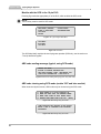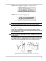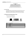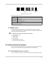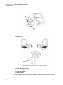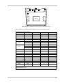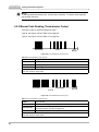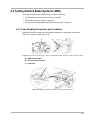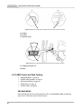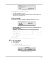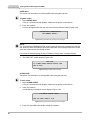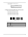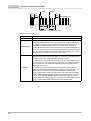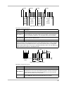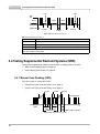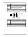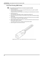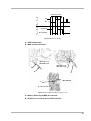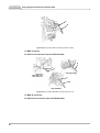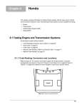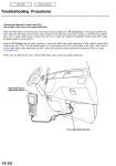
1
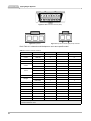
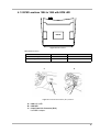
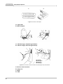
Acura
Chapter 4
This chapter contains information for testing Acura vehicles with the Asian Import Vehicle
Communication Software (VCS). The following Acura systems may be available for testing:
•
•
•
•
Engine
Transmission
Antilock Brake System (ABS)
Airbag (SRS)
4.1 Testing Engine Systems
Acura engine system testing includes:
•
•
•
•
•
•
“Code Reading Connectors and Locations” on page 17
“ECM Locations 1986 to 1990 with ECM LED”
“SCS mode” on page 21
“Code Type” on page 24
“Manual Code Reading (Engine Codes)” on page 24
“Multiple Codes” on page 25
4.1.1 Code Reading Connectors and Locations
Refer to Figure 4-1 for common diagnostic connector locations for Acura vehicles. Connector
configurations are shown in Figure 4-2, Figure 4-3 and Figure 4-4.
5
2
3
6
7
4
1
ENGINE
Figure 4-1 Common connector locations
17
Chapter 4 Acura
Testing Engine Systems
Figure 4-2 OBD-II data link connector (DLC)
Figure 4-3 3-pin DLC
Figure 4-4 2-pin service check signal (SCS) connector
Refer Table 4-1 to determine which adapter to use to test a specific model.
Table 4-1 Common connector locations
VEHICLE
YEAR
SCS 2-PIN
2.2 CL
1997
3
5*
2.3 CL
1998–99
3
5*
2.5 TL
1995–98
2
5*
3.0 CL
1997–99
3
5*
3.2 CL
3.5 RL
Integra
5*
2003
7
2
5*
1999–2002
5*
2003
7
1996–2003
2
1992–95
1
1996–2001
1
5*
1
4
MDX
2001–04
NSX
1995–2003
RSX
2002–04
7
7
1
3*
SLX
1996–99
6**
3.2 TL
2004
6
NSX
2004
TSX
2004
3.5 RL
2004
* Remove ashtray
** Remove the DLC cover
18
DLC 16-PIN
2001–02
1996–98
3.2 TL
DLC 3-PIN
2
3
6
3
5*
4.1.2 ECM Locations 1986 to 1990 with ECM LED
1 2
ENGINE
Figure 4-5 LED Locations.
Table 4-2 LED locations
VEHICLE
YEAR
LED LOCATION
Integra
1986–89
1
Legend Sedan
1986–90
2
A
B
C
C
Figure 4-6 Acura data link connector (DLC) locations
A—1995 2.5, 3.2 TL
B—1995 NSX
C—16-pin Data Link Connector (DLC)
Use OBD-II adapter.
19
Chapter 4 Acura
Testing Engine Systems
A
B
Figure 4-7 Acura DLC and adapter
A—16-pin DLC
B—OBD-II adapter
A
B
Figure 4-8 Acura control module locations for LED code flashers
A—1986–89 Integra, 1986–90 Legend Sedan
B—1990–91 Integra, 1987–90 Legend Coupe
A
A
B
C
B
D
1991-94 NSX,
1991-95 Legend,
1992-95 Vigor,
1993-95 Integra
Figure 4-9 Acura check connector locations for Check Engine Lamp code flashers
A—Service check connector
B—Jump wire
C—ECM
D—TCM
20
4.1.3 SCS mode
Purpose of SCS (Service Check Signal) mode:
•
•
•
•
i
Enables a diagnostic mode
Flash out DTCs stored for the PCM, ABS, TCS, and SRS modules
Code clearing on certain ABS systems
Bypass two trip detection mode for ODB-II drive cycles
NOTE:
Certain OBD-II vehicles use a separate 2 pin SCS connector. Other ODB-II models use a SCS
pin in the 16 PIN DLC. Both function the same way. For specific applications, refer to “Code
Reading Connectors and Locations” on page 17.
Models with a separate 2 pin SCS connector:
CODES MENU
HOW TO GET CODES
MANUAL CODE ENTRY
CLEAR CODES
JUMP 2-PIN SERVICE CONNECTOR
UNDER GLOVE BOX. CODE FLASH
ONE TIME PER IGNITION CYCLE ABS LAMP
FLASH CODE. CODE TYPE 04
Figure 4-10 Typical screen menu for the 2 pin SCS. Use jumper or Honda tool O.E. #07PAZ-0010100
21
Chapter 4 Acura
Testing Engine Systems
Models with the SCS in the 16 pin DLC:
Pressing Y grounds the appropriate pin of the DLC, which enables the SCS mode.
i
NOTE:
The K-18 key must be used for SCS mode.
MAIN MENU (ENGINE)
CODES & DATA MENU
SCS MODE
MOVIES
CUSTOM SETUP
TROUBLESHOOTER
Figure 4-11 Typical Engine Main Menu
SCS MENU:
SCS MODE
SCS HELP
Figure 4-12 SCS Menu
The SCS help briefly explains the two trip bypass operation (PCM only, see the section on
“Two-trip detection bypass”
ABS code reading message (typical, using SCS mode)
SELECT:SCS MODE
FOLLOW ON SCREEN INSTRUCTIONS.
ABS LAMP FLASHES CODES. SEE MANUAL FOR
CODE TYPE INFORMATION. CODE TYPE 04
Figure 4-13 ABS code reading message (typical, using SCS mode)
ABS code clearing using SCS mode (certain 1997 and later models)
When instructed by the scanner, ABS codes may be cleared using the SCS mode.
1)
2)
3)
4)
HOLD BRAKE ON & CYCLE IGNITION ON.
WHEN ABS LAMP GOES OFF-RELEASE BRAKE
WHEN LAMP COMES ON-HOLD BRAKE AGAIN
RELEASE BRK-WHEN LAMP GOES OFF. [MORE]
Figure 4-14 ABS clearing using SCS mode
SOME VEHICLES MAY REQUIRE TO BE DRIVEN
ABOVE 7-MPH TO COMPLETE CODE CLEARING
PROCEDURE.
Figure 4-15 ABS clearing using SCS mode
22
AIRBAG code reading message (typical, using SCS mode)
SELECT: SCS MODE
FOLLOW ON SCREEN INSTRUCTIONS.
SRS LAMP FLASHES CODES. SEE MANUAL FOR
CODE TYPE INFORMATION. CODE TYPE 06.
Figure 4-16 AIRBAG code reading message (typical, using SCS mode)
AIRBAG code clearing message (typical)
OR CENTER CONSOLE. SEE SMALL REFERENCE
FIND YELLOW MES CONNECTOR IN FUSE BOX
MANUAL FOR DETAILED CLEAR CODES
PROCEDURE.
Figure 4-17 AIRBAG code clearing message (typical, see code clearing section in this manual)
i
NOTE:
The MES (Message Erase SIgnal) connector is not the same as the SCS connector.
Two-trip detection bypass
Use SCS mode to bypass ODB ‘two trip detection’ and re-create certain DTCs during
diagnosis. Some codes require a back driving sequence (two road tests) where the fault must
occur in a similar operating condition.
i
NOTE:
On ODB-II vehicles with the separate 2 pin SCS connector, jumper the 2 pin connector for the
SCS mode functions.
A DTC can be captured in one driving event by connecting the scanner and selecting ‘SCS”
mode from the main menu (on applicable vehicles). For scan data usage during SCS mode,
manually jump the DLC from the backside while the scanner is connected to the DLC.
A
A
B
C
B
D
1991-94 NSX,
1991-95 Legend,
1992-95 Vigor,
1993-95 Integra
Figure 4-18 Data connector from the wire side (Honda numbering, not the same as SAE)
23
Chapter 4 Acura
Testing Engine Systems
View From Terminal Side
Figure 4-19 Data connector from terminal side (SAE standard pin numbering)
4.1.4 Code Type
For those systems that rely on manual code reading, you must interpret a DTC from a flashing
indicator lamp. The code flash sequence varies by model and system. The Scanner™
therefore refers you to a certain ‘code type’ (i.e. COPE TYPE 03). Code type is a specific
labeling system that identifies the appropriate section in this manual for each subsystem.
4.1.5 Manual Code Reading (Engine Codes)
There are 2 types of manual engine codes:
• Type 02, see Figure 4-20 and Table 4-3
• Type 03, see Figure 4-21 and Table 4-4
Key On Pulse
Code 5
Code
Repeats
Figure 4-20 Acura engine Code Type 02
Table 4-3 Acura engine Code Type 02
Pattern:
Long and short
Read codes on:
Red LED on ECU
Start codes by:
Turn the ignition on.
When done:
Turn the ignition off and clear codes.
Only one code displays at a time except on some late-model cars. After repairs, clear codes and test
drive, then check for other codes.
24
Second Digit
First Digit
Code 25
Code
Repeats
Figure 4-21 Acura engine Code Type 03
Table 4-4 Acura engine Code Type 03
Pattern:
Long and short
Read codes on:
Red LED on ECM; except most 1991 and later flash codes on CHECK engine
lamp on dash
Start codes by:
Turn the ignition on; except most 1991 and later, jumper the check connector,
then turn the ignition on.
When done:
Turn the ignition off and clear codes.
Only one code displays at a time except on some late-model cars. After repairs, clear codes and test
drive, then check for other codes.
4.1.6 Multiple Codes
The 1990 and later Integra and the 1991 Legend and NSX pulse multiple codes with a
2-second pause between each code. All other Acura models, including the 1990 Legend, with
an ECM, do not have multiple code memory.
z
To read codes for vehicles without multiple code capability:
1. Read the trouble code.
2. Fix the problem.
3. Reset the ECM.
4. Drive the vehicle.
5. Check the LED for a new code.
6. Continue until no codes are present.
4.2 Testing Transmission Systems
These instructions for reading manual codes only apply to 2001 and earlier models. 2002 and
later models have CODES & DATA selections available from the MAIN MENU.
4.2.1 Code Reading Connector Locations
Figure 4-22 and Figure 4-23 provide diagnostic connector locations and adapter information.
25
Chapter 4 Acura
Testing Transmission Systems
A
B
Figure 4-22 1991–95 NSX, 1992–95 Vigor transmission service check connector locations
A—Service check connector
B—Jump wire
A
B
C
D
Figure 4-23 Acura transmission service check connector locations
A—1987–90 Legend Coupe
B—1988–90 Legend Sedan
C—1990–95 Integra
D—LED display
Figure 4-24 shows common transmission diagnostic connector locations for Acura vehicles.
26
5
2
6
3
7
4
1
ENGINE
Figure 4-24 Common transmission connector locations for 1995–2003 vehicles
Refer to Table 4-5 to determine which adapter to use to test a specific model.
Table 4-5 Common connector locations
VEHICLE
YEAR
SCS 2-PIN
2.2 CL
1997
3
5*
2.3 CL
1998–99
3
5*
2.5 TL
1995–98
2
5*
3.0 CL
1997–99
3
5*
3.2 CL
DLC 16-PIN
2001–02
5*
2003
7
1996–98
3.2 TL
DLC 3-PIN
2
5*
1999–02
5*
2003
7
3.5 RL
1996–2003
2
5*
Integra
1996–2001
1
4
MDX
2001–04
NSX
1995–2003
RSX
2002–04
7
SLX
1996–99
6**
TSX
2004
6
3.2 TL
2004
6
NSX-T
2004
3
3.5 RL
2004
7
1
3
3*
5*
* Remove ashtray
** Remove the DLC cover
27
Chapter 4 Acura
i
Testing Transmission Systems
NOTE:
To retrieve codes with the scan tool, use the 16-pin connector. To retrieve codes manually,
use the SCS connector.
4.2.2 Manual Code Reading (Transmission Codes)
There are 2 types of manual transmission codes:
Type 02, see Figure 4-25 and Table 4-6 on page 28
Type 03, see Figure 4-26 and Table 4-7 on page 28.
Key On Pulse
Code 5
Code
Repeats
Figure 4-25 Acura transmission Code Type 02
Table 4-6 Acura transmission Code Type 02
Pattern:
Straight count
Read codes on:
Red LED on TCM
Start codes by:
Turn the ignition on.
When done:
Turn the ignition off, then clear codes.
Only one code displays at a time except on some late-model cars. After repairs, clear codes and test
drive, then check for other codes.
Second Digit
First Digit
Code 25
Code
Repeats
Figure 4-26 Acura transmission Code Type 03
Table 4-7 Acura transmission Code Type 03
Pattern:
Long and short
Read codes on:
Red LED on TCM or gear indicator lamp on dash
Start codes by:
Turn the ignition on; except for 1991 and later Vigor, Legend, and NSX, jumper
the check connector, then turn the ignition on.
When done:
Turn the ignition off, then clear codes.
Only one code displays at a time except on some late-model cars. After repairs, clear codes and test
drive, then check for other codes.
28
4.3 Testing Antilock Brake Systems (ABS)
Acura antilock brake system (ABS) testing includes the following:
• “Code Reading Connectors and Locations” on page 29
• “ABS Codes and Data Testing” on page 30
• “Manual Code Reading (ABS Codes) and Clearing Codes” on page 33
4.3.1 Code Reading Connectors and Locations
Diagnostic connector locations and test adapter information for Acura ABS are shown in
Figure 4-27, Figure 4-28 and Figure 4-29.
A
B
C
Figure 4-27 1991–95 NSX, 1992–94 Vigor, 1991–94 Legend ABS controller and service check connector locations
A—ABS indicator lamp
B—Service check connector
C—Jump wire
Figure 4-28 1986–90 Legend ABS controller and service check LED location
29
Chapter 4 Acura
Testing Antilock Brake Systems (ABS)
A
B
C
C
Figure 4-29 1990–93 Integra ABS controller and service check connector locations
A—4-door
B—3-door
C—Access cover
A
B
Figure 4-30 1996–97 SLX ABS controller and service check connector locations
A—Jump pin 4 to pin 12
B—DLC
4.3.2 ABS Codes and Data Testing
•
•
•
•
•
“ABS MAIN MENU” on page 30
“CODES & DATA MENU” on page 31
“DATA (NO CODES)” on page 31
“CODE ONLY” on page 32
“CLEAR CODE” on page 32
ABS MAIN MENU
After selecting ABS from the System Selection menu, the MAIN MENU (ABS) is displayed
(Figure 4-31). Selections vary by model and year.
30
MAIN MENU
>CODES & DATA MENU
CUSTOM SETUP
MOVIES
TROUBLESHOOTER
Figure 4-31 Typical ABS main menu
The following main menu selections are discussed:
• “CODES & DATA MENU” on page 31
• MOVIES, CUSTOM SETUP, and TROUBLESHOOTER are discussed in detail in the
user’s manual for your diagnostic tool.
CODES & DATA MENU
When CODES & DATA MENU is selected, the following is displayed (Figure 4-32):
CODES & DATA MENU
>DATA (NO CODES)
CODE ONLY
CLEAR CODE
REVIEW CODES
PRINT CODES
Figure 4-32 Typical ABS CODES & DATA MENU
• DATA (NO CODES) - This selection begins communication with the ABS module and
displays data parameters.
• CODE ONLY - When selected, ABS trouble codes are gathered and displayed.
• CLEAR CODES - This selection clears ABS memory codes from the ABS ECM memory.
• REVIEW CODES - This selection allows you to view codes. (This menu item appears only
after code gathering.)
• PRINT CODES - This selection allows you to print codes. (This menu item appears only
after code gathering.)
DATA (NO CODES)
This section has information on viewing ABS data using the scan tool.
z
To enter and exit ABS data:
1. Enter in the vehicle ID.
2. Turn the ignition on.
3. Select DATA (NO CODES)
4. Turn the ignition off after completing the ABS data tests.
**ABS DATA**
LF WHEEL(MPH)_____0 RF WHEEL(MPH)______0
LR WHEEL(MPH)_____0 RR WHEEL(MPH)______0
BRAKE SW________OFF ABS PUMP MOTOR____OFF
Figure 4-33 Typical ABS DATA display
31
Chapter 4 Acura
Testing Antilock Brake Systems (ABS)
CODE ONLY
This section has information on retrieving ABS codes using the scan tool.
z
To gather codes:
1. Select CODES ONLY.
A “key on” verification screen displays. Make sure the ignition is switched on.
2. Press Y to continue.
A screen will appear while the scan tool communicates with the vehicle (Figure 4-34).
INITIALIZING COMMUNICATION
ONE MOMMENT PLEASE...
Figure 4-34 Typical ABS code reading screen message
i
NOTE:
The “INTIALIZING COMMUNICATION” screen means the scan tool is attempting to start the
test, however it does not mean the vehicle has responded. If the message stays on the screen
more than a few minutes, the test did not start.
If no codes are detected during the test a “P0000 no faults present” message displays
3. The CODE LIST screen appears (Figure 4-35)
CODE LIST
12-3 WHEEL SPEED SENSOR CIRCUIT OPEN
END OF LIST
Figure 4-35 Typical ABS codes message
CLEAR CODE
This section has information on clearing ABS codes using the scan tool.
z
To clear codes:
1. Select CLEAR CODES.
A “key on” verification screen displays. Make sure the ignition is switched on.
2. Press Y to continue.
A code clearing confirmation screen displays (Figure 4-36).
DTC ERASE ROUTINE (KOEO)
ARE YOU SURE? PRESS Y OR N.
Figure 4-36 Typical ABS code clearing screen message
3. Press Y to clear ABS codes or N to cancel the operation.
32
4. The DTCs CLEARED screen appears (Figure 4-37)
Press Y or N to exit.
DTCs CLEARED
PRESS Y OR N
Figure 4-37 Typical ABS codes cleared screen message
4.3.3 Manual Code Reading (ABS Codes) and Clearing Codes
There are several types of manual codes for Acura ABS:
•
•
•
•
•
Type 02, see Figure 4-38 and Table 4-8 on page 33
Type 04, see Figure 4-39 and Table 4-9 on page 34
Type 5a, see Figure 4-40 and Table 4-10 on page 35
Type 06, see Figure 4-41 and Table 4-11 on page 35
Type 12, see Figure 4-42 and Table 4-12 on page 36
Second Digit
First Digit
Code 25
Code
Repeats
Figure 4-38 Acura ABS Code Type 02
Table 4-8 Acura ABS Code Type 02
Pattern:
Straight count
Read codes on:
ABS lamp on dash
Start codes by:
Jumper the check connector, then turn the ignition on.
When done:
Turn the ignition off, then clear codes.
Only one code displays at a time except on some late-model cars. After repairs, clear codes and test
drive, then check for other codes.
33
Chapter 4 Acura
Testing Antilock Brake Systems (ABS)
1.3 Sec.
2.0
Sec.
0.4 Sec.
3.6
Sec.
3.0
Sec.
Start of Next Code
Key On
Pulse
3
4
Code 34
Figure 4-39 Acura ABS Code Type 04
Table 4-9 Acura ABS Code Type 04
34
Pattern:
10s and 1s
Read codes on:
ABS warning lamp
Start codes by:
For 2003–04 NSX: Short SCS connector and turn key on; (do not press brake
pedal). ABS indicator will stay on for 2 seconds then turn off. Main code will flash
then pause 0.4 seconds, sub-code will flash and pause 3.6 seconds. If a DTC is
not available, the ABS lamp will go off for 3.6 seconds then come back on.
For other models: Short SCS connector and turn key on; ABS indicator light will
stay on for 2 seconds then turn off; main code will flash then pause 0.4 seconds;
sub-code will flash and pause 3.6 seconds; stored codes will flash only one time
per ignition cycle; cycle key at least once to verify codes.
Clear codes:
For 2000–02 3.5 RL: Press parking brake pedal; with SCS shorted, hold VSA
switch in the off position and turn the ignition on; hold for 3–5 seconds until VSA
light blinks 4 times; this signals that codes have been cleared.
For 2003-2004 RL: Press parking brake pedal. Push VSA ‘OFF’ switch, hold it,
then turn ignition on. Hold VSA switch for 3-5 seconds, then release VSA switch.
After 3 seconds, the VSA indicator should blink 4 times. This signals that the
codes have been cleared.
For 2003–04 NSX: With the SCS shorted, press the brake pedal and cycle
ignition on. After the ABS indicator goes off, release the brake pedal. After the
ABS indicator comes back on, depress brake pedal again. After the ABS
indicator goes off again, release the brake pedal. After a few seconds the ABS
indicator will blink twice and the DTC is cleared. Turn ignition off and un-short the
SCS connector.For other models: With the SCS shorted, cycle key on with
brake pedal pressed; ABS light will turn on, then shut off; release pedal and light
will turn on; press brake pedal until light turns off and release pedal.
3.2 Sec.
1
2
0.4 Sec.
2
1.2 Sec.
3
1
0.4 Sec.
3
2
5
Repeats
3 Tmes
Repeats
3 Tmes
Repeats
3 Tmes
Repeats
3 Tmes
Current
Code 12
(Begin)
Current
Code 23
History
Code 13
(Begin)
History
Code 25
Figure 4-40 Acura ABS Code Type 5a
Table 4-10 Acura ABS Code Type 5a
Pattern:
10s and 1s
Read codes on:
ABS warning lamp
Start codes by:
After bringing the vehicle to a complete stop and making sure the brake pedal is
not depressed, turn the ignition switch to the off position. Connect terminals 12
and 4 on the OBD-II 16-pin DLC. Turn the ignition switch to the ON position.
Clear codes by:
Within three seconds after entering the diagnostic mode, pulsate the brake
switch on and off at least six times.
When done:
Turn the ignition off, disconnect connectors, then clear codes.
All codes repeat three times and are followed by a 1.2-second pause. Code 12 always flashes first to
confirm the system is in the diagnostic mode. Any current codes follow code 12. Code 13 indicates
the presence of history codes which then follow. If only history codes are present, the diagnostic
sequence will first flash code 12, then code 13, followed by the history codes. The code display cycle
repeats as long as the system is in the diagnostic state.
1.3 Sec.
3.6
Sec.
3.0
Sec.
Key On
Pulse
3
Start of
Next Code
2
Code 32
Figure 4-41 Acura ABS Code Type 06
Table 4-11 Acura ABS Code Type 06
Pattern:
Main code and sub-code
Read codes on:
ABS warning lamp
Start codes by:
Short the SCS connector and turn key on; ABS indicator light will stay on for 2
seconds then turn off; main code will flash then pause 1 second; sub-code will
flash and pause 5 seconds; stored codes will flash only one time per ignition
cycle; cycle key at least once to verify codes.
When done:
To clear codes, remove ABS B2 (15A) fuse in the ABS fuse box for 10
seconds.NSX only: Remove #2 and #3 ABS fuse for 10 seconds.
35
Chapter 4 Acura
Testing Supplemental Restraint Systems (SRS)
1 Sec.
1 Sec.
LED
On
10 Sec.
5 Sec.
4
5 Sec.
3
2
5
2
Ignition On
Code 43
Code 52
Code 2
Figure 4-42 Acura ABS Code Type 12
Table 4-12 Acura ABS Code Type 12
Pattern:
Main code and sub-code
Read codes on:
Red LED on antilock brake controller
Start codes by:
Turn the ignition on.
When done:
Turn the ignition off, then clear codes.
Only one code displays at a time except on some late-model cars. After repairs, clear codes and test
drive, then check for other codes.
4.4 Testing Supplemental Restraint Systems (SRS)
Testing Acura supplemental restraint systems (SRS), or airbag systems, includes:
• “Manual Code Reading (SRS)” on page 36
• “Code Clearing (SRS Codes)” on page 38
4.4.1 Manual Code Reading (SRS)
There are 2 types of manual SRS codes:
• Type 06, see Figure 4-43 and Table 4-13 on page 37
• Type 07, see Figure 4-44 and Table 4-14 on page 37
0.1 Sec.
1.2 Sec.
0.3 Sec.
Start of Next Code
3.0
Sec.
Key On
Pulse
2.0
Sec.
10 + 10
2
10s Digit
1s Digit
(=20)
(=2)
Main Code
3
Sub
Code
Main + Sub = Code 22-3
Figure 4-43 Acura SRS Code Type 06
36
Table 4-13 Acura SRS Code Type 06
Pattern:
Main code and sub-code
Read codes on:
SRS warning lamp
Start codes by:
Short the SCS connector and turn key on; SRS warning lamp will turn on then
turn off after 3.0 seconds; if the code is greater than 10, four quick flashes (0.1
seconds each) = 10; main code will flash and pause 2.0 seconds and flash again
if code is greater than 1; after a 2.0 second pause, sub-code will now flash in 0.3
second pulses, followed by more flashes if code is greater than 1.
When done:
Clear codes. If the SCS connector is shorted and SRS has no stored DTC, it’s
normal to see the SRS light remain on continuously.
Computer can store up to 3 most recent codes.
The SCS is part of the 16-pin DLC; ground pin #9 to activate.
3.5 RL only: SCS connector is separate from the 16-pin DLC. The 2-pin SCS connector is located
under the glove box.
1.2 Sec.
0.3 Sec.
2.0
Sec.
2.0
Sec.
Key On
Pulse
2
Start of Next Code
3
Code 23
Figure 4-44 Acura SRS Code Type 07
Table 4-14 Acura SRS Code Type 07
Pattern:
Main code and sub-code
Read codes on:
SRS warning lamp
Start codes by:
Short the SCS connector and turn key on; SRS warning lamp will turn on then
turn off; after 2.0 seconds, main code will flash, pause 1.2 seconds, and flash
again if code is greater than 1; add the flashes together for main code; after a 2.0
second pause, sub-code will now flash in 0.3 second pulses and flash again if
code is greater than 1; add the flashes together for sub-code.
When done:
Clear codes.
Computer can store up to 3 most recent codes.
If the SCS connector is shorted and SRS has no stored DTC, it’s normal to see the SRS light remain
on continuously. 1995–96 2.5 TL models are different, if no DTCs are stored, the SRS lamp will flash
continuously without pausing.
37
Chapter 4 Acura
Testing Supplemental Restraint Systems (SRS)
4.4.2 Code Clearing (SRS Codes)
z
To clear DTCs from the SRS unit on all models except SLX and NSX:
1. Switch the ignition off.
2. Connect the SCS service connector (Acura 07PAZ-0010100) to the yellow 2-pin MES
connector (Figure 4-45 on page 38).
A jumper wire can be used as long as you maintain good contact between the terminals.
3. Switch the ignition on.
The SRS indicator lamp lights for about 6 seconds, then switches off.
4. Remove the SCS service connector from the MES connector within 4 seconds of the lamp
switching off.
5. When the SRS indicator lamp lights again, connect the SCS service connector to the MES
connector within 4 seconds of the lamp switching on.
6. When the SRS indicator lamp switches off, remove the SCS service connector from the
MES connector within 4 seconds.
The SRS lamp flashes twice to indicate memory has been erased.
7. Switch the ignition off and wait ten seconds.
Figure 4-45 SCS Service Connector OEM# 07PAZ-0010100 (or use jumper wire equivalent)
38
4 seconds or Less
On
A
Off
Connected
B
Disconnected
Figure 4-46 SRS code clearing
A—SRS indicator lamp
B—MES connector terminals
1996–1998 3.2 TL,
1996–2004 3.5 RL
1999–2003 3.2 TL,
2001–2003 3.2 CL A
A
B
B
2002–2004 RSX
A
B
Figure 4-47 Acura OBD-II SRS MES connector (1 of 2)
A—Memory Erase Signal (MES) 2P connector
B—SCS Service connector (Acura 07PAZ-0010100)
39
Chapter 4 Acura
Testing Supplemental Restraint Systems (SRS)
A
B
Figure 4-48 2004 TSX/TL SRS code clearing (left side of dash)
A—MES connector
B—SCS service connector (Acura 07PAZ-0010100)
A
B
A
B
1996–2001 Integra
1997 2.2 CL,
1997–1999 3.0 CL,
1998–1999 2.3 CL
A
B
2001–2004 MDX
Figure 4-49 Acura OBD-II SRS MES connector location (2 of 2)
A—MES 2P connector
B—SCS Service connector (Acura 07PAZ-0010100)
40