1
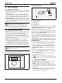
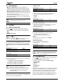
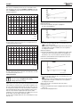
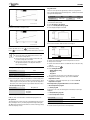
SETTINGS 12.4 OPERATING MODES >> Number of hours • With electric additional heat; the electric additional heat is permitted to work at the same time as the heat pump to meet the demand, when the heat pump cannot meet it by itself. Alarm mode, Extra hot water and Hot water peak also activate the additional heat. • With mixed additional heat (option); mixed additional heat which is permitted to work at the same time as heat pump. The additional heat is also used during alarm operation. A hot water electric heater is required for production of extra hot water and hot water peak. In this case, the electric additional heat in the heat pump is disabled. Factory setting Lowest value Highest value The Multi module accessory is required for mixed additional heat and hot water electric heater. 0h 0h 99h Table 6 Party duration ▶ Select the number of hours that party mode should be active for. The function starts immediately on all activated circuits. >> Circuit 1 >> Circuit x Factory setting Alternative No No/Yes Table 7 Enable party mode 13 ▶ Select Yes to enable party mode. Party mode can be enabled for each installed circuit. The menu is displayed only if more than one circuit is installed. SETTINGS >> Deactivate party mode 13.1 MODE BUTTON FUNCTIONS By pressing • • • • , the following functions can be used directly: Room temperature normal / Temperature increase/decrease Party Holiday Extra hot water duration The button can be used to change the language of the control unit. ▶ Hold down the button for at least five seconds in the initial menu and then select language. Factory setting Alternative No No/Yes Table 8 Deactivate party mode ▶ Select Yes to disable party mode on all activated circuits. The heat pump returns to program mode. The menu is displayed only if party mode is active. > Holiday The same functions are included here as in the Holiday menu ( Chapter 13.4). > Extra hot water duration > Room temperature normal / Temperature increase/decrease Here, temperature changes for Circuit 1 can be made. If this circuit is equipped with a room temperature sensor, the display shows Room temperature normal, otherwise Temperature increase/decrease is shown. Factory setting Lowest value Highest value 20.0 °C 10.0 °C 35.0 °C Table 4 Room temperature, normal Factory setting Alternative = – – , – , =, +, ++ ▶ For a description of setting Extra hot water (Chapter 13.3). Factory setting Lowest value Highest value 0h 0h 48h Table 9 Extra hot water duration After a period with blocked hot water production, e.g., holiday, it is recommended to enable the extra hot water function so as to eliminate bacteria and quickly reach the correct hot water temperature. Table 5 Room temperature increase/decrease 13.2 ROOM TEMPERATURE ▶ Use this function to simply increase or decrease the heat when there are no room controllers. – – gives approx. 1 °C lower room temperature. – gives approx. 0.5 °C lower room temperature. + gives approx. 0.5 °C higher room temperature. ++ gives approx. 1 °C higher room temperature. Press the button in the standard display to open the main menu. Select Room temperature to adjust the heating. It always takes some time for a change of a heating setting, e.g. an increase or decrease in room temperature, to apply. The same applies in the event of a quick change of the outdoor temperature. This is why you should always wait for at least 24 hours before making a new change. > Party Party mode means that a running room program is stopped during the set time in order to avoid a temperature drop. 6 720 802 172 (2012/06) The following options are available under Room temperature: • Circuit 1 Heating • Circuit 2, 3... • General > Circuit 1 Heating >> Heat curve The heat curve constitutes the basis for the control unit's control of the temperature on the heating water to the circuit and indicates how high it needs to be in relation to the outdoor temperature. The control unit increases the temperature of the heating water when the outdoor temperature drops. The temperature of the heating water out to the circuit, i.e. the flow temperature is measured by sensor T1 for circuit 1 (full name E11.T1) and sensor T1 for circuit 2 (full name E12.T1). 11