1
USER MANUAL
USER INSTRUCTIONS
WORCESTER GREENSTORE LECP GROUND SOURCE HEAT
PUMP IN EITHER SYSTEM OR COMBI VARIANTS
6 720 802 172-01.1I
6KW, 7KW, 9KW AND 11KW
6 720 802 172 (2012/06) en
UK/IE
CONTENTS
CONTENTS
1
Key to symbols and safety instructions . . . . . . . . . . . . . . . . . . . 2
1.1
Key to symbols . . . . . . . . . . . . . . . . . . . . . . . . . . . . . . . . . 2
1.2
Safety instructions . . . . . . . . . . . . . . . . . . . . . . . . . . . . . . 3
2
The Benchmark Scheme . . . . . . . . . . . . . . . . . . . . . . . . . . . . . . . . 3
3
Ground source heat pump operation . . . . . . . . . . . . . . . . . . . . . 3
3.1
Selection and sizing of a heat pump . . . . . . . . . . . . . . . . . 3
4
Heat emitters . . . . . . . . . . . . . . . . . . . . . . . . . . . . . . . . . . . . . . . . . 3
5
Use . . . . . . . . . . . . . . . . . . . . . . . . . . . . . . . . . . . . . . . . . . . . . . . . . . 4
5.1
General . . . . . . . . . . . . . . . . . . . . . . . . . . . . . . . . . . . . . . . 4
5.2
Heat pump function . . . . . . . . . . . . . . . . . . . . . . . . . . . . . . 4
6
Energy measurement . . . . . . . . . . . . . . . . . . . . . . . . . . . . . . . . . . 5
7
Control unit . . . . . . . . . . . . . . . . . . . . . . . . . . . . . . . . . . . . . . . . . . 6
7.1
Additional heat . . . . . . . . . . . . . . . . . . . . . . . . . . . . . . . . . 6
7.2
Hot water production . . . . . . . . . . . . . . . . . . . . . . . . . . . . 6
8
Control panel . . . . . . . . . . . . . . . . . . . . . . . . . . . . . . . . . . . . . . . . . 6
8.1
Panel overview . . . . . . . . . . . . . . . . . . . . . . . . . . . . . . . . . 6
8.2
On/Off button . . . . . . . . . . . . . . . . . . . . . . . . . . . . . . . . . . 6
8.3
Status lamp . . . . . . . . . . . . . . . . . . . . . . . . . . . . . . . . . . . . 6
8.4
Menu display . . . . . . . . . . . . . . . . . . . . . . . . . . . . . . . . . . . 6
8.5
Menu button and menu dial . . . . . . . . . . . . . . . . . . . . . . . 6
8.6
Return button . . . . . . . . . . . . . . . . . . . . . . . . . . . . . . . . . . 6
8.7
Mode button . . . . . . . . . . . . . . . . . . . . . . . . . . . . . . . . . . . 6
8.8
Info button . . . . . . . . . . . . . . . . . . . . . . . . . . . . . . . . . . . . . 6
9
Menu overview . . . . . . . . . . . . . . . . . . . . . . . . . . . . . . . . . . . . . . . 7
10 Menu navigation . . . . . . . . . . . . . . . . . . . . . . . . . . . . . . . . . . . . . . 7
10.1 Initial menu . . . . . . . . . . . . . . . . . . . . . . . . . . . . . . . . . . . . 7
10.2 Finding desired function and changing values . . . . . . . . 7
10.3 Help information in the menu display . . . . . . . . . . . . . . . 8
11 Information from the heat pump . . . . . . . . . . . . . . . . . . . . . . . . . 9
11.1 Operating information . . . . . . . . . . . . . . . . . . . . . . . . . . . . 9
11.2 Info button . . . . . . . . . . . . . . . . . . . . . . . . . . . . . . . . . . . . . 9
11.3 Operating symbols . . . . . . . . . . . . . . . . . . . . . . . . . . . . . . 9
12 Heating, general . . . . . . . . . . . . . . . . . . . . . . . . . . . . . . . . . . . .
12.1 Circuits for heating . . . . . . . . . . . . . . . . . . . . . . . . . . . .
12.2 Control methods for heating . . . . . . . . . . . . . . . . . . . . .
12.3 Time control for heating . . . . . . . . . . . . . . . . . . . . . . . .
12.4 Operating modes . . . . . . . . . . . . . . . . . . . . . . . . . . . . . .
2
10
10
10
10
11
13 Settings . . . . . . . . . . . . . . . . . . . . . . . . . . . . . . . . . . . . . . . . . . . . 11
13.1 Mode button functions . . . . . . . . . . . . . . . . . . . . . . . . . . 11
13.2 Room temperature . . . . . . . . . . . . . . . . . . . . . . . . . . . . . 11
13.3 Hot water . . . . . . . . . . . . . . . . . . . . . . . . . . . . . . . . . . . . . 15
13.4 Holiday . . . . . . . . . . . . . . . . . . . . . . . . . . . . . . . . . . . . . . . 16
13.5 Energy measurements . . . . . . . . . . . . . . . . . . . . . . . . . . 16
13.6 Timers . . . . . . . . . . . . . . . . . . . . . . . . . . . . . . . . . . . . . . . 16
13.7 External control . . . . . . . . . . . . . . . . . . . . . . . . . . . . . . . . 16
13.8 General . . . . . . . . . . . . . . . . . . . . . . . . . . . . . . . . . . . . . . 17
13.9 Alarms . . . . . . . . . . . . . . . . . . . . . . . . . . . . . . . . . . . . . . . 17
13.10 Access level . . . . . . . . . . . . . . . . . . . . . . . . . . . . . . . . . . . 18
13.11 Return to factory settings . . . . . . . . . . . . . . . . . . . . . . . . 18
14 Alarms . . . . . . . . . . . . . . . . . . . . . . . . . . . . . . . . . . . . . . . . . . . . . . 18
14.1 Control unit and room controller alarm lamp . . . . . . . . 18
14.2 Alarm buzzer at alarm . . . . . . . . . . . . . . . . . . . . . . . . . . . 18
14.3 Acknowledgement of alarms . . . . . . . . . . . . . . . . . . . . . 18
14.4 Alarm timer, alarm mode . . . . . . . . . . . . . . . . . . . . . . . . 18
14.5 Alarm categories . . . . . . . . . . . . . . . . . . . . . . . . . . . . . . . 19
14.6 Alarm window . . . . . . . . . . . . . . . . . . . . . . . . . . . . . . . . . 19
14.7 Alarm functions . . . . . . . . . . . . . . . . . . . . . . . . . . . . . . . . 19
14.8 Warnings . . . . . . . . . . . . . . . . . . . . . . . . . . . . . . . . . . . . . 22
14.9 Information log . . . . . . . . . . . . . . . . . . . . . . . . . . . . . . . . 23
15 Energy savings . . . . . . . . . . . . . . . . . . . . . . . . . . . . . . . . . . . . . . 24
16 Maintenance . . . . . . . . . . . . . . . . . . . . . . . . . . . . . . . . . . . . . . . . 24
16.1 Checking the safety valves . . . . . . . . . . . . . . . . . . . . . . . 24
16.2 Expansion vessel . . . . . . . . . . . . . . . . . . . . . . . . . . . . . . . 24
16.3 Particle filter . . . . . . . . . . . . . . . . . . . . . . . . . . . . . . . . . . 24
17 The guarantee . . . . . . . . . . . . . . . . . . . . . . . . . . . . . . . . . . . . . . . 24
1
KEY TO SYMBOLS AND SAFETY
INSTRUCTIONS
1.1
KEY TO SYMBOLS
WARNINGS
Warnings in this document are identified by a warning
triangle printed against a grey background.
Keywords at the start of a warning indicate the type and
seriousness of the ensuing risk if measures to prevent
the risk are not taken.
The following keywords are defined and can be used in this document:
• NOTE indicates a situation that could result in damage to property or
equipment.
• CAUTION indicates a situation that could result in minor to medium
injury.
• WARNING indicates a situation that could result in severe injury or
death.
• DANGER indicates a situation that will result in severe injury or death.
6 720 802 172 (2012/06)
THE BENCHMARK SCHEME
IMPORTANT INFORMATION
3
This symbol indicates important information where
there is no risk to people or property.
ADDITIONAL SYMBOLS
Symbol
▶
•
–
Explanation
Step in an action sequence
Cross-reference to another part of the document
List entry
List entry (second level)
Table 1
1.2
SAFETY INSTRUCTIONS
GENERAL
▶ Read the guide carefully and keep it to hand for future use.
INSTALLATION AND COMMISSIONING
▶ The heat pump may be installed and put into operation only by a
competent person.
RISK OF DAMAGE DUE TO OPERATOR ERROR
Operator errors can result in injury and damage to property.
▶ Ensure that children never operate this appliance unsupervised or
play with it.
▶ Ensure that only personnel who can operate this appliance correctly
have access to it.
GROUND SOURCE HEAT PUMP OPERATION
As the outside temperature gets colder, the heat demand of a house
increases and the output of a ground source heat pump will decrease.
Eventually it becomes so cold outside that the output of the heat pump
alone is not able to heat the building effectively. The Greestore range of
ground source heat pumps therefore allows for monoenergetic and
bivalent operation.
Monoenergetic means that in the event of very low external
temperatures a 3-stage electrical booster heater in the indoor unit will
automatically be activated to provide additional heat if required and
keep the building warm.
In bivalent operation a second heating appliance (e.g. gas or oil boiler) is
used to supplement the heat load.
3.1
SELECTION AND SIZING OF A HEAT PUMP
It is essential that heat pump systems are designed to operate efficiently
in order to meet the building heating needs and the expectations of the
customer. In order to achieve this, the following design activities must
be completed prior to installation:• Pre-design assessment - Determine the suitability of a heat pump
system for the building based on the customer requirements,
expectations and building type.
• Detailed design - Complete building heat loss calculations and
domestic hot water usage assessment.
• Specification - Select a suitable heat pump and system components
based on the detailed design. Calculate and communicate the
predicted energy use and running costs of the system to the
customer.
▶ Only competent persons may carry out repairs. Incorrect repairs can
lead to serious risks to the user, and a reduction in savings.
▶ Only use original spare parts.
▶ Service and maintenance must be carried out annually by a competent
person.
A suitable design methodology for the above is detailed in MIS3005, the
Microgeneration Certification Scheme (MCS) heat pump installer
standard. Worcester, Bosch Group recommended that this standard is
followed for heat pump systems. The standard covers the design,
installation and commissioning requirements to ensure that 100% of the
building heat loss can be met efficiently by the heat pump system. A heat
pump system must be designed to this standard to be eligible for
government financial incentives e.g Renewable Heat Incentive (RHI).
2
The Worcester Bosch Group design team offer a heat pump sizing
service which is MCS compliant. To request this service, download and
submit the form using the guidance notes from our website address:
SERVICE AND MAINTENANCE
THE BENCHMARK SCHEME
Worcester, Bosch Group is a licensed member of the Benchmark
Scheme which aims to improve the standards of installation and
commissioning of domestic heating and hot water systems in the UK and
to encourage regular servicing to optimise safety, efficiency,
performance and to comply with the F gas regulations.
Please ensure that the installer has fully completed the Benchmark
Checklist on the inside back pages of the installation instructions
supplied with the product and that you have signed it to say that you
have received a full and clear explanation of its operation. The installer is
legally required to complete a commissioning checklist as a means of
complying with the appropriate Building Regulations (England and
Wales).
All installations should be made in accordance with MCS/MIS 3005.
This product should be serviced regularly to optimise its safety,
efficiency and performance. The service engineer should complete the
relevant Service Record on the Benchmark Checklist after each service.
The Benchmark Checklist may be required in the event of any warranty
work and as supporting documentation relating to home improvements
in the optional documents section of the Home Information Pack.
www.worcester-bosch.co.uk/hp
4
HEAT EMITTERS
Worcester, Bosch Group heat pumps are fitted with weather
compensation controls as standard. However, for a heat pump to
perform to its highest energy efficiency, the central heating emitter
circuit should be designed so that the flow temperature is as low as
possible.
As a guide, the system should be designed using the following maximum
flow temperatures;
• Underfloor heating: 35-40 °C
• Radiators: 45-50 °C
If underfloor heating has been installed, it is important to remember that
the underfloor system designer should have been informed that the heat
source will be from an air source heat pump. It is also important to
remember that radiators should have been correctly sized to work
effectively with lower flow temperatures.
A tool to aid installers and end users to understand the relevance of
building heat loss and heat emitter selection on heat pump performance,
has been created by the joint trade associations. The 'Heat Emitter
Guide' can be downloaded from the following website:
www.microgenerationcertification.org
6 720 802 172 (2012/06)
3
USE
5
USE
5.1
GENERAL
The Worcester Greenstore series is equipped with the latest generation
low energy circulation pumps on both the cold and hot sides. Low energy
circulation pumps are being introduced in line with future European
legislation. They are designed to improve the system efficiency.
When purchasing the equipment, the installation engineer must make an
energy estimate and assess the degree of energy coverage for the heat
pump system in line with current guide lines.
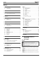
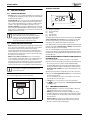
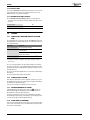
Greenstore Combi/System is a series of heat pumps that use stored
solar energy in order to provide water-based heating and hot water.
1
2
3
6 720 614 540-01.2I
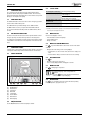
Fig. 1
[1]
[2]
[3]
Stored solar energy
Rock heat
Soil heat
Lake heat
Greenstore 6-11 Combi are heat pumps with integrated domestic hot
water cylinders.
Greenstore 6-11 System are heat pumps designed to be supplemented
with external domestic hot water cylinders.
Once the heat pump has been installed and started, there are a number
of points that should be checked regularly. This may concern an alarm
triggering or performing basic maintenance actions. If the problem is
repeated, you should contact your installer.
5.2
HEAT PUMP FUNCTION
The heat pump consists of four main parts:
• Evaporator
Evaporates the refrigerant to gas and at the same time transfers the
heat from the collector to the refrigerant circuit.
• Condenser
Condenses the gas to fluid again and transfers the heat to the heating
system.
• Expansion valve
Lowers the pressure of the refrigerant.
• Compressor
Increases the pressure of the refrigerant.
These four main parts are linked in three circuits. A refrigerant circulates
in the heat pump, which in some parts of the circuit is in a liquid state and
in other parts in a gas state.
4
6 720 802 172 (2012/06)
ENERGY MEASUREMENT
1
2
3
4
5
6
7
12
10
9
8
11
6 720 614 540-02.3I
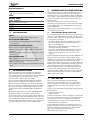
Fig. 2
[1]
[2]
[3]
[4]
[5]
[6]
[7]
[8]
[9]
[10]
[11]
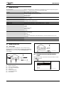
[12]
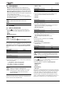
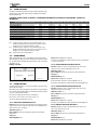
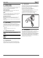
Heat pump description
Collector circuit pump
Evaporator
Compressor
Condenser
Heat pump domestic hot water cylinder
Floor heating
Radiator
Heat pump
Heat carrier pump
Expansion valve
Borehole
Geothermal heating coil (horizontal loop/compact collector)
• The collector circuit fluid, which is a mixture of water and anti-freeze,
circulates in the borehole/geothermal heating coil in a plastic hose.
The fluid collects stored solar energy and with the help of the collector
circuit pump leads it into the heat pump and to the evaporator. The
temperature is then approximately 0 °C.
• In the evaporator the collector circuit fluid meets the refrigerant. The
refrigerant is then in a fluid state and is at approximately -10 °C. When
the refrigerant meets the zero degree heat transfer fluid, it starts to
boil. Vapour forms and is led into the compressor. The temperature of
the vapour is approximately 0 °C
• In the compressor, the pressure on the refrigerant increases and the
temperature of the vapour rises to approximately +100 °C. The hot
vapour is then forced into the compressor.
• In the condenser the heat is transferred to the house heating system
(radiators and underfloor heating) and the hot water system. The
vapour cools and liquefies. The pressure in the refrigerant is still high
when it is led on to the expansion valve.
• The pressure of the refrigerant is reduced in the expansion valve. The
temperature also drops to approximately -10 °C. When the refrigerant
passes the evaporator it changes to vapour again.
6 720 802 172 (2012/06)
• The collector circuit is led out from the heat pump to the borehole/
geothermal heating coil to collect new stored solar energy. The
temperature of the fluid is then approximately -3 °C.
6
ENERGY MEASUREMENT
The control unit has the ability to measure the amount of energy that is
produced by the heat pump unit. The calculation assumes that, for
example, the heat pump is correctly installed and that the flow and
temperatures on the hot and cold sides are adjusted as recommended.
The value should therefore be regarded as an estimate of the actual
emitted output. The margin of error in the calculation is normally put at
5-10%.
In addition, the energy output is affected by the outdoor temperature,
the settings for the thermostat and room controls and heat pump usage.
Ventilation, indoor temperature and hot water demand can play a
decisive role.
5
CONTROL UNIT
7
CONTROL UNIT
The control unit controls and monitors the heating and hot water
production with the heat pump and additional heat. The monitoring
function shuts down the heat pump in the event of a fault so as to prevent
damage to critical parts of the pump.
7.1
ADDITIONAL HEAT
The additional heat becomes active in the event of emergency operation,
extra hot water and hot water peak.
The additional heat is provided through electric additional heat.
The Multi module accessory is required for mixed additional heat.
The control unit will automatically activate the additional heat, when
needed.
7.2
HOT WATER PRODUCTION
Hot water is heated in the domestic hot water cylinder and the control
unit gives priority to hot water before production of heating water
according to the settings that are made. The domestic hot water cylinder
is fitted with a sensor that senses the temperature of the domestic hot
water.
8.3
The lamp lights continuously.
The lamp flashes rapidly.
The heat pump is running.
There is an alarm that has not been
acknowledged.
The alarm has been acknowledged
but the alarm cause remains.
The lamp flashes slowly, menu The heat pump is in stand-by mode1).
window not lit.
The lamp and menu display not No voltage to the control unit.
lit.
Table 2 Lamp functions
1) Stand-by means that the heat pump control unit has been turned off but with
electrical power still supplied to the unit.
8.4
CONTROL PANEL
Settings for the control of the heat pump are made with the control unit's
control panel, which also provides information about current status.
8.1
PANEL OVERVIEW
MENU DISPLAY
Use the menu display in order to:
• View information from the heat pump.
• View available menus.
• Change set values.
8.5
8
STATUS LAMP
MENU BUTTON AND MENU DIAL
Use
to get from Initial menu to the menus. Use the menu dial in
order to:
• Navigate the menus and get to the setting displays.
– Turn the dial to see more menus on the same level or change a set
value.
– Press the dial to change to a lower menu level or save a change.
8.6
Use
RETURN BUTTON
to:
• Go back to the previous menu level.
• Leave a setting display without changing the set value.
8.7
Use
MODE BUTTON
to change type of operation.
The controller language can be changed with the
button.
▶ Press the
button in the initial menu for at least 5
s, then select the required language.
8.8
INFO BUTTON
Use
to see information from the control unit about operating
mode, temperature, program version, etc.
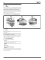
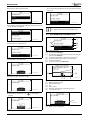
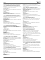
Fig. 3
[1]
[2]
[3]
[4]
[5]
[6]
[7]
[8]
8.2
The control panel
On/Off button
Mode button
Info button
Menu dial
Status lamp
Return button
Menu button
Menu display
ON/OFF BUTTON
Use the On/Off button to turn the heat pump on and off.
6
6 720 802 172 (2012/06)
MENU OVERVIEW
9
MENU OVERVIEW
Room temperature
Hot water
Holiday
Energy measurements
Timers
External control
General
Alarms
Circuit 1 Heating (Heat curve, Compressor x operating time on/off, Room temperature program)
Circuit 2, 3... (option) (Heat curve, Room temperature program)
General (Summer/winter operation)
Extra hot water (period, Stop temperature)
Hot water peak (Day of the week, Interval, Time)
Hot water program
Hot water mode
Circuit 1 and Hot water
Circuit 2, 3... (option)
Generated energy
Consumption electric additional heat
Active timers are shown, e.g. Extra hot water duration
Heat pump x (External input 1, 2, External input circuit 2, 3... (option))
Room sensor settings (room controller)
Set date
Set time
Summer/winter time
Display contrast
Language
Information log
Delete information log
Alarm log
Delete alarm log
Alarm indication (Alarm buzzer signal, Alarm indication control unit and Room sensor (room
controller))
Access level
Return to factory settings
Table 3 Menu overview
10
MENU NAVIGATION
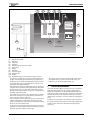
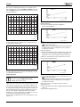
10.1 INITIAL MENU
Initial menu shows different temperatures, time, as well as current
operating symbols. The window displays information alternately Room
temperature (if room controllers exist) and Flow temperature for each
circuit installed.
6 720 614 789-02.1I
Fig. 5
Initial menu, circuit 2 is shown if installed
10.2 FINDING DESIRED FUNCTION AND CHANGING
VALUES
7
Menu overview ( Page 7) shows the main functions that are reached
with
and the dial.
▶ Press
.
6 720 614 789-12.1I
Fig. 4
[1]
[2]
[3]
[4]
[5]
[6]
[7]
Initial menu
Outdoor temperature
Current operating symbols
The circuit room temperature
Current time
Hot water temperature
Circuit flow temperature
Circuit number
6 720 802 172 (2012/06)
6 720 643 415-01.1I
Fig. 6
7
MENU NAVIGATION
The control unit automatically returns to the menu when the value has
been saved.
▶ Turn the dial to mark a desired menu bar.
6 720 643 415-02.1I
6 720 643 415-08.1I
Fig. 7
▶ Select the function by pressing the dial. The first three menu functions
under Hot water are displayed.
Fig. 13
Economy and Comfort are explained in more detail in
the chapter about hot water mode ( Chapter 13.3).
10.3 HELP INFORMATION IN THE MENU DISPLAY
6 720 643 415-03.1I
Fig. 8
6
▶ Turn the dial to see other menu lines.
6 720 643 415-09.1I
Fig. 14 Help information 1
[1]
[2]
6 720 643 415-04.1I
[3]
[4]
[5]
[6]
Fig. 9
▶ Press the dial to select the function.
The menu level is Hot water
Drop-down list. The marked row shows your position among the
functions under Hot water.
The arrow shows that there is new menu on the next level.
The points show that the next level is a setting window.
The function is marked.
Three of the functions under Hot water.
6 720 643 415-05.1I
Fig. 10
▶ Turn the menu dial to change the set value.
6 720 643 415-10.1I
Fig. 15 Help information 2
6 720 643 415-06.1I
[1]
[2]
[3]
[4]
[5]
[6]
Graphic display of the value.
Highest possible value.
Unit.
Previous value.
New value. (Saved when the menu dial is pressed.)
Lowest possible value
Fig. 11
▶ Press the dial to save the value or use
changing.
to return without
6 720 643 415-11.1I
Fig. 16 Help information 3
[1]
Option 4 out of 9 is displayed.
6 720 643 415-07.1I
Fig. 12
8
6 720 802 172 (2012/06)
INFORMATION FROM THE HEAT PUMP
11
INFORMATION FROM THE HEAT PUMP
The heat pump provides information about temperatures, operating
modes, possible alarms, etc.
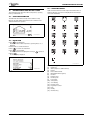
11.3 OPERATING SYMBOLS
Symbols for different functions and components for which there is a
demand or which are in operation are displayed in the bottom right
corner of the Initial menu.
11.1 OPERATING INFORMATION
The Initial menu shows different temperatures and times of day.
Different operating symbols show the functions for which there are
demand or which are in operation.
1
2
3
4
5
6
7
8
9
10
11
12
13
14
15
6 720 614 789-01.1I
Fig. 17
11.2 INFO BUTTON
▶ Press
in the Initial menu.
Detailed information about temperatures, operating mode, etc., is
displayed.
▶ Turn the dial to see all the information.
▶ Press
to return to the initial menu.
▶ Press
in a menu display.
The detailed information is displayed for as long as
is pressed.
▶ Release
.
The menu display is displayed.
16
6 720 802 133-01.1I
Fig. 19 Operating symbols
6 720 643 415-12.1I
Fig. 18
6 720 802 172 (2012/06)
[1]
[2]
[3]
[4]
[5]
[6]
[7]
[8]
[9]
[10]
[11]
[12]
[13]
[14]
[15]
[16]
Compressor
Alarm (compressor, additional heat)
Heating
Electric additional heat
Mixed additional heat (option)
Hot water
Extra hot water
Hot water peak
Pool (option)
Solar (option)
Screed drying
External control
Program/time control
Party
Holiday
Information log
9
HEATING, GENERAL
THE DISPLAY FUNCTIONS
12
HEATING, GENERAL
1 2
12.1 CIRCUITS FOR HEATING
• Circuit 1; the first circuit is included by default in the control unit and
is controlled by the installed flow sensor, can also be controlled with
the optional room controller.
• Circuit 2 (mixed); control of circuit 2 is also included by default in the
control unit but needs to be supplemented with an external mixing
valve, circulation pump and flow sensor and also an additional room
controller - these parts are all available as optional accessories.
• Circuits 3-4 (mixed); control of up to 2 additional circuits is optional.
Each circuit is then fitted with a Multi module, mixing valve, circulation
pump, flow sensor and possibly a room controller, these parts are all
available as optional accessories.
Circuits 2 through 4 cannot have a higher flow
temperature than circuit 1. This means that underfloor
heating on circuit 1 cannot be combined with radiators
on another circuit. Room temperature reduction for
circuit 1 can affect other circuits in some cases.
12.2 CONTROL METHODS FOR HEATING
• Outdoor sensor; a sensor is fitted on a north facing outside wall of the
house. The sensor sends signals to the control unit in the heat pump.
Control with an outdoor sensor means that the heat pump
automatically regulates the heating in the house depending on the
outdoor temperature. The customer determines the temperature of
the heating system in relation to the outdoor temperature by setting
the heat curve on the control unit.
• Outdoor sensor and room controllers (one room controller per
circuit is possible); Control with outdoor sensor supplemented with
room controller(s) means that one (or several) controllers are
mounted in specified areas of the property. They are connected to the
heat pump and provide the control unit with information about the
current room temperature. The signal will affect the flow temperature.
It is only the room where the room controller is located
that can influence regulation of the temperature for the
relevant heating circuit.
12.2.1 LCD ROOM CONTROLLER (ACCESSORY)
The control unit supports up to four room controllers.
3
12 3 4 5 6 7
5
4
6 720 648 080-08.1I
Fig. 21
[1]
[2]
[3]
[4]
[5]
Outdoor temperature
Room temperature
Holiday
Extra hot water
Current circuit
The display window shows the current room temperature. When Show
outdoor temperature in room sensor (room controller) is set to Yes
the outdoor temperature is also shown, alternating with the room
temperature. This is valid for all installed room controllers.
In the display window, operating symbols can appear at the bottom right
hand side. The symbol for Extra hot water or Holiday is displayed when
the function has been set in the heat pump.
The room controller display is used to indicate alarms for some alarm
categories ( Table 46 ). The display window slowly flashes red until
the alarm has been acknowledged in the heat pump control unit, or been
automatically reset.
SETTING THE ROOM TEMPERATURE WHEN A ROOM CONTROLLER
HAS BEEN INSTALLED
The room temperature can easily be set using the room controller.
▶ Turn the room controller knob to set the desired room temperature for
the circuit. The previous set value is shown with blinking digits.
The display blinks during the setting and stops blinking shortly after
turning of the knob has stopped. The value in the control unit menu
Room temperature normal for the circuit is automatically set to the
same value.
Alternatively the desired room temperature is set via the control unit.
▶ Go to the menu Room temperature normal for the circuit and set the
desired room temperature.
The room temperature value in the room controller for the circuit is
automatically set to the same value.
For Circuit 1 there is one more way to set the room temperature.
▶ Use
to set the room temperature in Room temperature normal
( Chapter 13.1).
12.3 TIME CONTROL FOR HEATING
6720648080-00.1I
Fig. 20 CAN-BUS LCD room controller
10
• Program control; The control unit offers a possibility to define two
individual programs for time control of the heating.
• Holiday; the control unit has a program for holiday mode, which
means that during the selected period the room temperature changes
to a lower or higher level. The program also allows switching off hot
water production.
• External control; the control unit can make settings for external
control, which means that the preselected function is performed
when the control unit senses an input signal.
6 720 802 172 (2012/06)
SETTINGS
12.4 OPERATING MODES
>> Number of hours
• With electric additional heat; the electric additional heat is
permitted to work at the same time as the heat pump to meet the
demand, when the heat pump cannot meet it by itself. Alarm mode,
Extra hot water and Hot water peak also activate the additional heat.
• With mixed additional heat (option); mixed additional heat which is
permitted to work at the same time as heat pump. The additional heat
is also used during alarm operation.
A hot water electric heater is required for production of extra hot
water and hot water peak. In this case, the electric additional heat in
the heat pump is disabled.
Factory setting
Lowest value
Highest value
The Multi module accessory is required for mixed
additional heat and hot water electric heater.
0h
0h
99h
Table 6 Party duration
▶ Select the number of hours that party mode should be active for.
The function starts immediately on all activated circuits.
>> Circuit 1
>> Circuit x
Factory setting
Alternative
No
No/Yes
Table 7 Enable party mode
13
▶ Select Yes to enable party mode.
Party mode can be enabled for each installed circuit. The menu is
displayed only if more than one circuit is installed.
SETTINGS
>> Deactivate party mode
13.1 MODE BUTTON FUNCTIONS
By pressing
•
•
•
•
, the following functions can be used directly:
Room temperature normal / Temperature increase/decrease
Party
Holiday
Extra hot water duration
The
button can be used to change the language of
the control unit.
▶ Hold down the
button for at least five seconds
in the initial menu and then select language.
Factory setting
Alternative
No
No/Yes
Table 8 Deactivate party mode
▶ Select Yes to disable party mode on all activated circuits.
The heat pump returns to program mode.
The menu is displayed only if party mode is active.
> Holiday
The same functions are included here as in the Holiday
menu ( Chapter 13.4).
> Extra hot water duration
> Room temperature normal / Temperature increase/decrease
Here, temperature changes for Circuit 1 can be made. If this circuit is
equipped with a room temperature sensor, the display shows Room
temperature normal, otherwise Temperature increase/decrease is
shown.
Factory setting
Lowest value
Highest value
20.0 °C
10.0 °C
35.0 °C
Table 4 Room temperature, normal
Factory setting
Alternative
=
– – , – , =, +, ++
▶ For a description of setting Extra hot water
(Chapter 13.3).
Factory setting
Lowest value
Highest value
0h
0h
48h
Table 9 Extra hot water duration
After a period with blocked hot water production, e.g.,
holiday, it is recommended to enable the extra hot water
function so as to eliminate bacteria and quickly reach the
correct hot water temperature.
Table 5 Room temperature increase/decrease
13.2 ROOM TEMPERATURE
▶ Use this function to simply increase or decrease the heat when there
are no room controllers.
– – gives approx. 1 °C lower room temperature.
– gives approx. 0.5 °C lower room temperature.
+ gives approx. 0.5 °C higher room temperature.
++ gives approx. 1 °C higher room temperature.
Press the
button in the standard display to open the main menu.
Select Room temperature to adjust the heating.
It always takes some time for a change of a heating
setting, e.g. an increase or decrease in room
temperature, to apply. The same applies in the event of a
quick change of the outdoor temperature. This is why
you should always wait for at least 24 hours before
making a new change.
> Party
Party mode means that a running room program is stopped during the
set time in order to avoid a temperature drop.
6 720 802 172 (2012/06)
The following options are available under Room temperature:
• Circuit 1 Heating
• Circuit 2, 3...
• General
> Circuit 1 Heating
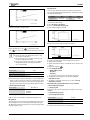
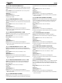
>> Heat curve
The heat curve constitutes the basis for the control unit's control of the
temperature on the heating water to the circuit and indicates how high it
needs to be in relation to the outdoor temperature. The control unit
increases the temperature of the heating water when the outdoor
temperature drops. The temperature of the heating water out to the
circuit, i.e. the flow temperature is measured by sensor T1 for circuit 1
(full name E11.T1) and sensor T1 for circuit 2 (full name E12.T1).
11
SETTINGS
Each circuit is controlled by its own heat curve. The installer sets the
type of heating for each circuit, that is Radiator or Underfloor. The heat
curve for Underfloor has lower values because the floors do not tolerate
such high temperatures.
T1(˚C)
80
70
6 720 614 789-18.3I
60
Fig. 24 Settings window Heat curve (radiator)
50
Change the left point:
▶ Press the menu dial when the square is highlighted.
The value is then highlighted.
40
30
20
10
20
15
10
5
0
-5
-10
-15
-20
-25
-30
-35
T2(˚C)
6 720 614 789-15.3I
Fig. 22 Radiator
6 720 614 789-19.3I
The figure indicates the factory setting curve for a radiator circuit. At 2.5 °C the flow set point is 37.4 °C.
T1(˚C)
80
70
Fig. 25
▶ Turn the menu dial to change the value. Press the dial to save or use
to return without saving.
In the window, the square is highlighted again and any changed values
are displayed after the square. In addition, the curve is updated
according to the new value.
Change the right point:
▶ Turn the menu dial when the square is highlighted. The upper square
is changed to outdoor temperature with the corresponding curve
value after the colon. The circle marks the relevant curve position.
60
50
▶ Continue to turn the dial until it shows a square before the colon.
▶ Press the dial to highlight the value.
40
30
20
10
20
15
10
5
0
-5
-10
-15
-20
-25
-30
-35
T2(˚C)
6 720 614 789-16.3I
Fig. 23 Floor
The figure indicates the factory setting curve for an underfloor circuit. At
-2.5 °C the flow set point is 27.2 °C.
Setting of heat curve
If the heat curve has been set too high, the display will
show the message Too high heat curve setting.
▶ Change the heat curve setting.
A heat curve is set for each circuit. If the room temperature is perceived
to be too high or too low in the circuit, it is preferable to adjust the curve.
The curve can be changed in different ways. The slope of the curve can
be changed by offsetting the flow temperature upwards or downwards
on the left-hand side (the value at outdoor temperature 20 °C, factory
value 22.0 °C) as well as the right-hand side (the value at outdoor
temperature -35 °C, factory setting 60.0 °C). In addition, the curve can
be affected by every 5th outdoor temperature degree.
The value at 0 °C is displayed above the curve's left-hand point, factory
value 35.7 °C.
12
6 720 614 789-23.3I
Fig. 26
▶ Turn the menu dial to change the value. Press the dial to save or use
to return without saving.
In the window, the square is highlighted again and any changed values
are displayed after the square. In addition, the curve is updated
according to the new value.
Change a specific value, for example the value at an outdoor
temperature of 0 °C:
▶ Turn the menu dial when the square is highlighted until 0 °C is marked
( Fig. 27).
▶ Press the dial to highlight the value.
6 720 802 172 (2012/06)
SETTINGS
Program 1 and 2
These selections provide an opportunity to define user programs for
time control by adjusting the start and stop times, as well as a normal and
an programmed temperature.
Program
Program 1, 2
Day
Mon - Sun
Start
5:30
Stop
22:00
Table 12 Program 1 and 2
6 720 614 789-21.3I
Fig. 27
▶ Turn the menu dial to change the value.
To set the desired time of day:
▶ Select Program 1 or Program 2.
▶ Go to menu View/edit active program.
▶ Select day by turning the menu dial.
6 720 643 415-13.1I
Fig. 29
6 720 614 789-22.3I
▶ Press the menu dial to mark the value to be changed.
Fig. 28
▶ Press the dial to save or use
to return without saving.
▶ Use
to leave the curve setting window and return to the menu.
Recommendations:
▶ Increase the value of the right point if it feels too cold
at low outdoor temperatures.
▶ Increase the value of curve at 0 °C if it feels a little cold
at outdoor temperatures around 0.
▶ Increase or decrease the value of the curve equally at
the right and left points to fine adjust the heat (the
curve is offset parallel).
>> Compressor x operating time on/off
Factory setting
Lowest value
Highest value
20.0
10.0 (Comfort)
30.0 (Economy)
Table 10 Compressor operating time on/off
6 720 643 415-14.1I
Fig. 30
▶ Turn the menu dial until the desired setting has been selected.
▶ Then press the menu dial.
▶ Turn the menu dial to be able to set additional values in the same way
as above.
▶ Go back one step with
.
▶ Select Saving alternative:
– Return without saving
– Program 1
– Program 2
The set changes are saved as a selected program or not at all.
▶ To adjust the normal temperature, proceed to menu Room
temperature normal.
▶ To adjust the exceptional temperature, proceed to menu Room
temperature exception.
▶ Select how long the compressor should be on or off in heating mode.
Higher set values result in fewer compressor starts and stops, which
achieves higher economy. However, more pronounced temperature
fluctuations in the heating system may result than with lower values.
Room temperature program when there is a room controller:
>> Room temperature program
>> Room temperature program
Factory setting
Alternative
>>> Active program
HP optimized
• HP optimized
• Program 1
• Program 2
If a program is selected, the following (if the menu button is turned) is
displayed:
>>> View/edit active program
Table 11 Program selection, circuit 1
>>> Room temperature normal
▶ Choose if the circuit should be controlled with a program or not.
Factory setting
Lowest value
Highest value
HP optimized
This means that the control unit is only controlled by the flow set point
value ( Chapter 13.2.1), without programmed changes during the
day. Optimised operation provides the best comfort and energy savings
in the vast majority of cases.
6 720 802 172 (2012/06)
20.0 °C
10.0 °C
35.0 °C
Table 13 Room temperature, normal
▶ Set the desired set point for the room temperature.
13
SETTINGS
>>> Copy to all heating circuits
>>> Room temperature exception
Factory setting
Lowest value
Highest value
17.0 °C
10.0 °C
30.0 °C
Table 14 Room temperature, exception
▶ Set the temperature that should apply as programmed temperature in
the program.
The menu is displayed only if Program 1or Program 2has been
selected.
>>> Copy to all heating circuits
Factory setting
Alternative
No
No/Yes
Table 15 All circuits
▶ Select Yes to have the same control for all installed circuits.
The menu is displayed only under Circuit 1.
Room temperature program when there is no room controller:
>> Room temperature program
>>> Active program
>>> View/edit active program
The same as when there is a room controller, see above.
>>> Room temperature normal
Factory setting
Lowest value
Highest value
20.0 °C
10.0 °C
35.0 °C
Table 16 Room temperature, normal
▶ Set the measured value in the room.
The indicated value is used by temperature programs to calculate the
difference between normal and exceptional temperature.
>>> Temperature increase/decrease
Factory setting
Alternative
=
– – , – , =, +, ++
The same as when there is a room controller, see above.
It always takes some time for a change of a heating
setting, e.g. an increase or decrease in room
temperature, to apply. The same applies in the event of a
quick change of the outdoor temperature. This is why
you should always wait for at least 24 hours before
making a new change.
> Circuit 2, 3... (Circuit 3 option)
Circuit 2, 3... has the same settings options as Circuit 1, (
Chapter 13.2).
13.2.1 SET POINT
The heating circuit's set point value is the temperature of the flow that
the heat pump attempts to maintain. Sometimes, the measured actual
value fluctuates a bit upward and downward depending on changes in
the outdoor temperature or a large hot water demand.
The set point value specified by the customer/installer is
most often the room temperature, which is recalculated
by the control unit into a corresponding flow
temperature set point value. Under normal conditions, 1
K ( °C) in room temperature corresponds to approx. 3 K
( °C) in flow temperature.
The set point value is normally based on:
• Current curve value (the flow temperature at the current outdoor
temperature according to the applicable heat curve).
• Current curve influence through:
– Room sensor (room controller)
– Holiday
– Active program
– External control
SET POINT VALUE CALCULATION
The set point value for the heating circuit is the current curve value
adjusted with active curve influence, if any such exists.
Table 17 Room temperature increase/decrease
Priority order for curve influence is:
▶ Use this function to adjust the room temperature so that the normal
room temperature (see the previous menu) becomes the desired
temperature.
▶ Use this function to simply increase or decrease the heat when there
are no room controllers.
– – gives approx. 1 °C lower room temperature.
– gives approx. 0.5 °C lower room temperature.
+ gives approx. 0.5 °C higher room temperature.
++ gives approx. 1 °C higher room temperature.
• External control
• Active program
• Holiday
> Room temperature influence
Factory setting
Lowest value
Highest value
3.0
0.0
10.0
Table 18 Room temperature influence
▶ Set how much a 1 K ( °C) difference in room temperature should
influence the set point value for the flow temperature.
Example: at a 2 K ( °C) deviation from the set room temperature, the
set point value for the flow temperature is changed by 6 K ( °C) (2 K
deviation * factor 3 = 6 K).
>>> Room temperature exception
The same as when there is a room controller, see above.
14
Only one of these can be active. How big the influence should be and
when to exercise it is set in the respective function.
FIXED SET POINT VALUE
A fixed set point value (not curve-based) applies in the event of:
• External set point value. The set point value is determined according
to input signal 0-10V where 1V is 10 °C and 10V is 80 °C (0V triggers
an alarm).
SET POINT VALUE LIMITATION
The calculated set point value is always checked against the permitted
temperature limits.
The applicable set point value T1 for Circuit 1 and the measured actual
value for T1 are used to activate and deactivate the heat demand.
The following applies to Circuit 2, 3...: When the actual value for the
mixed circuit's T1 is low in relation to the set point value, more heating
water is shunted into the circuit so as to maintain the set point value.
If the flow temperature has been below the set point value for a certain
period of time, there is heat demand and the compressor produces heat
before there is a too significant temperature reduction indoors. This
happens until the flow temperature is a couple of degrees higher than
6 720 802 172 (2012/06)
SETTINGS
the set point value. (Or because Maximum operating time for heating
at hot water demand has passed.)
Heating demand is not active during summer operation.
> General
DANGER: Risk of burn injuries.
▶ Use a mixing valve when the hot water temperature
exceeds 60 °C.
>> Summer/winter operation
> Hot water peak
>>> Winter operation
Hot water peak means a temporary increase in the hot water
temperature to approx. 65 °C for thermal elimination of bacteria
(pasteurisation).
Factory setting
Alternative
Automatic
On/Automatic/Off
Table 19 Summer/winter operation
For the hot water temperature increase, the compressor is used first;
the additional heat source then continues alone.
If On is selected, the heat pump is constantly in winter operation and
heat and hot water are always produced. Off signifies constant summer
operation; only hot water is produced. Automatic signifies change-over
at the set outdoor temperature.
>> Day of the week
>>> Outdoor temperature limit for change over
Table 23 Weekday
Factory setting
Lowest value
Highest value
▶ Set the day on which the hot water peak should take place. None
means that the function is disabled. All means that a hot water peak
takes place every day.
If hot water peak is deactivated comfort mode must be selected in the
menu Hot water mode.
18 °C
5 °C
35 °C
Table 20 Change over temperature
The menu is displayed only if Automatic has been selected in Winter
operation.
In the event of alternation between winter and summer
operation and vice versa, there is a certain delay aimed
at preventing constant starting and stopping of the
compressor when the outdoor temperature oscillates
around the temperature limit.
13.3 HOT WATER
Under Hot water, there are functions to:
• Request Extra hot water
• Specify when Hot water peak should be performed to eliminate
bacteria
• Set any Hot water program
• Select operating mode
> Extra hot water
Additional amount of hot water is produced by temporarily increasing
the temperature of the hot water during the set number of hours to the
indicated stop temperature.
>> Extra hot water duration
Factory setting
Lowest value
Highest value
0h
0h
48h
Table 21 Extra hot water duration
Factory setting
Area
Wednesday
None, Day, All
>> Interval in weeks
Factory setting
Lowest value
Highest value
1
1
4
Table 24 Week interval
▶ Set how often a hot water peak should take place.
– 1 means a hot water peak every week.
– 2 means that a hot water peak takes place in all even weeks of the
year, i.e. in week 2, 4, 6, etc.
– 3 means week 3, 6, 9, etc.
– 4 means week 4, 8, 12, etc.
>> Start time
Factory setting
Lowest value
Highest value
3:00
0:00
23:00
Table 25 Start time
▶ Set the time of the hot water peak.
WARNING: Risk of scalding.
At hot water temperatures greater than 60 °C, there is a
risk of scalding.
▶ Exercise caution when using hot water immediately
after a hot water peak.
▶ Set the duration of extra hot water production.
> Hot water program
>> Extra hot water stop temperature
Program 1 and Program 2 enables you to block hot water production
during the set time.
Factory setting
Lowest value
Highest value
65 °C
50 °C
65 °C
Table 22 Extra hot water stop temperature
>> Active program
Factory setting
Alternative
▶ Set the stop temperature for extra hot water.
The heat pump starts the function directly and uses the compressor first
and then the additional heat source to increase the temperature. When
the desired number of hours have passed, the heat pump returns to
normal hot water mode.
6 720 802 172 (2012/06)
Always hot water
• Always hot water
• Program 1
• Program 2
Table 26 Hot water program
15
SETTINGS
>> View/edit active program
> Circuit 2, 3...
The menu is displayed only if Program 1 or Program 2 has been
selected. Programs are changed in the same way as for Room
temperature program (Chapter 13.2).
>> Activate holiday function
> Hot water mode
Factory setting
Alternative
>> Start date
>> Stop date
>> Room temperature
Economy
Economy/Comfort
Table 27 Hot water mode
▶ Select hot water mode.
Economy means that the hot water is permitted to cool slightly before
hot water production starts compared to Comfort. Heating stops at a
slightly lower temperature.
▶ Change to Comfort if more or hotter hot water is desired.
This setting must be used if electric additional heat is missing or if the
hot water circulation is used, when the temperature in the hot water
circulation is otherwise too low.
The factory settings for on and off temperature are approx. 8 K ( °C)
lower in Economy mode compared to Comfort mode.
▶ Set the values in the same way as for Circuit 1 and hot water.
13.5 ENERGY MEASUREMENTS
Energy is measured per compressor; the calculated
results are added prior to being displayed.
> Generated energy
This displays Generated energy in kWh divided into Heating and Hot
water.
> Consumption electric additional heat
This displays Consumption electric additional heat in kWh divided into
Heating and Hot water.
13.4 HOLIDAY
13.6 TIMERS
During holidays (absence), the heating can, for example, be kept at a
lower or higher level and hot water production can be switched off. Start
and Stop date, Room temperature and Block hot water production are
only displayed if the holiday function is activated.
Timers are used by the control unit to count down the different time
dependent functions such as Extra hot water duration. At customer
level the following timers can be observed (only timers that are counting
are displayed):
> Circuit 1 and hot water
>> Activate holiday function
Factory setting
Alternative
No
No/Yes
Table 28 Holiday function
>> Start date
>> Stop date
▶ Set start and stop date for the desired period. Format yyyy-mm-dd.
The period starts and ends at 00:00. Both the start and end date are
included in the period.
▶ Terminate the period prematurely by indicating No in the menu
Activate holiday function.
>> Room temperature
17 °C
10 °C
35 °C
Table 32 Timers
When an external input is connected, the control unit performs functions
which are set to Yes or is separated from 0 (Room temperature). When
the external input is no longer connected, the control unit returns to
normal mode. Only installed functions are displayed.
> Heat pump x
>>> Block additional heat
No
Yes/No
>>> Block heating at tripped underfloor temperature limiter
>>> Block heating
Table 30 Copy circuits
>>> Room temperature
>> Block hot water production
>>> Block hot water production
Table 31 Block hot water
120min
20min
>>> Block compressor
>> Copy to all heating circuits
Factory setting
Alternative
10min
>> External input 1, 2
Table 29 Room temperature, holiday
Factory setting
Alternative
F value
0h
1h
0h
20min
30min
13.7 EXTERNAL CONTROL
▶ Set the room temperature that should apply to the circuit during the
period.
Factory setting
Lowest value
Highest value
Timer
Extra hot water
Alarm mode delay
Party
Operating time for heating at hot water demand
Hot water, operating time at heating demand
Heat pump x timers
> Compressor start delay
Additional heat timers
> Additional heat start delay
> Delay mixing valve control after additional heat start
No
Yes/No
>> External input circuit 2, 3...
>>> Block compressor
>>> Block additional heat
>>> Block heating at tripped underfloor temperature limiter
>>> Block heating
>>> Room temperature
>>> Block hot water production
16
6 720 802 172 (2012/06)
SETTINGS
13.9 ALARMS
Room temperature:
Factory setting
Lowest value
Highest value
No (0.0 °C)
10.0 °C
35.0 °C
Table 33 Room temperature
▶ Set the room temperature that should apply in the event of enabled
external control.
▶ Value > 0 °C enables the function.
The highest temperature is used if temperature changes have been set
for a certain circuit at several external inputs.
Other functions:
Factory setting
Alternative
No
Yes/No
The different alarms that can occur are described in (Chapter 14).
Under Alarms there is:
•
•
•
•
•
Information log
Delete information log
Alarm log
Delete alarm log
Alarm indication
> Information log
The information log shows information from the heat pump. The
information log symbol is displayed in the control panel initial menu
when there is active information.
> Delete information log
The information log is deleted here.
> Alarm log
Table 34 Functions
> Room sensor settings (room controller)
The alarm log shows the alarms and warnings that have occurred. Alarm
category ( Chapter 14.5) is displayed in the top left corner of the
display. If the alarm is active, the alarm symbol (Chapter 11.3) is
displayed both in the alarm log and the initial menu of the control panel.
>> Show outdoor temperature in room sensor (room controller)
> Delete alarm log
13.8 GENERAL
Among other things, settings for date and time are available here.
The alarm log is deleted here.
Factory setting
Alternative
No
Yes/No
Table 35 Show outdoor temperature in room controller
> Set date
Factory setting
Format
> Alarm indication
Settings for alarm buzzer and status lamp are made here.
>> Alarm buzzer signal
>>> Interval
Table 36 Date
Factory setting
Lowest value
Highest value
> Set time
Table 40 Interval
Factory setting
Format
▶ Set the length of the alarm interval.
The alarm buzzer sounds for one second and is silent during the rest
of the interval. The setting applies to all alarm buzzers.
yyyy-mm-dd
hh:mm:ss
Table 37 Time
2s
2s
3600s (60min)
>>> Blocking time
▶ Check and change, if necessary, date and time. These are used by the
control unit to manage the different clock settings, e.g., holiday and
room temperature program.
> Summer/winter time
Factory setting
Start time
Stop time
Off
0:00 - 23:45
0:00 - 23:45
Table 41 Blocking time
Factory setting
Alternative
Automatic
Manual/Automatic
Table 38 Summer/winter time.
▶ Set the times between which alarms buzzers should not be allowed to
produce an acoustic signal.
>> Alarm indication control unit
▶ Select if there should be automatic change over between summer and
winter time or not (dates according to EU standard).
>>> Block alarm buzzer
> Display contrast
Factory setting
Alternative
Factory setting
Lowest value
Highest value
70%
0%
100%
Table 39 Display contrast
▶ If necessary, change the background light of the control panel.
> Language
▶ Change language, if desired.
No
No/Yes
Table 42 Block alarm buzzer
The setting applies only to the control unit's alarm buzzer.
>> Alarm indication room sensor (room controller)
>>> Block alarm indicator lamp
Factory setting
Alternative
Yes
No/Yes
Table 43 Block indicator lamp
The setting applies to all room controllers.
6 720 802 172 (2012/06)
17
ALARMS
13.10 ACCESS LEVEL
Access level is Customer as standard: This level gives you access to all
functions that the user requires. The installer also has access to the
additional functions required at installation.
13.11 RETURN TO FACTORY SETTINGS
▶ Select Return to factory settings and Yes to reset all customer
settings to the factory settings. Settings made by the installer are not
affected.
Factory setting
Alternative
No
Yes/No
Table 44 Return to factory settings
14
ALARMS
14.1 CONTROL UNIT AND ROOM CONTROLLER ALARM
LAMP
The status lamp on the control unit is used to show ON/OFF status for the
heat pump but also to show possible alarms. The status lamp is therefore
also called alarm lamp.
Behaviour
Function
Blue, continuously lit. The heat pump is running.
Blue, flashing rapidly. There is an alarm which must be
acknowledged.
The alarm has been acknowledged but the
alarm cause remains.
Blue, flashing.
The heat pump is in standby mode1).
Table 45 Alarm lamp control unit
1) Stand-by means that the heat pump is running but no heating or hot water
demand exists.
The room controller display is used to indicate alarms for some alarm
categories ( Table 46 ). The display window slowly flashes red until
the alarm has been acknowledged in the heat pump control unit, or been
automatically reset.
The room controller alarm display function is referred to as alarm lamp in
this chapter.
The room controller alarm lamp can be blocked.
14.2 ALARM BUZZER AT ALARM
At an alarm the alarm buzzer on the heat pump sounds for one second
per alarm buzzer interval set. At certain times of the day the alarm buzzer
can be blocked or blocked altogether.
In the event of a warning, the alarm buzzer does not sound.
14.3 ACKNOWLEDGEMENT OF ALARMS
Acknowledgement means that you have to press
to make the
alarm window disappear. What happens after acknowledgement is
described in the respective alarm description.
In most cases, warnings do not have to be acknowledged. The alarm
window disappears by itself once the warning cause has disappeared. It
is, however, possible to acknowledge the warning.
14.4 ALARM TIMER, ALARM MODE
In the event of an alarm that stops the compressor the control unit starts
a timer at 1h. If the fault does not recur additional heat may start when
the timer has counted down.
18
6 720 802 172 (2012/06)
ALARMS
14.5 ALARM CATEGORIES
The alarms are divided into different categories depending on the type
and seriousness of the fault. Alarm category is displayed in the alarm
window and alarm log.
CATEGORIES A-H ARE ALARMS, CATEGORIES I-J ARE WARNINGS/INFORMATION, CATEGORIES K-M ARE WARNINGS, CATEGORY Z IS
INFORMATION.
Meaning
Stops the compressor
Stops additional heat
Alarm lamp, alarm buzzer is activated
Alarm delay
Requires acknowledgement to restart
Can be restarted before acknowledgement
Menu display must be acknowledged
Placed in the information log
A
X
B
X
C
X
D
X
E
X
X
5s
X
X
3s
X
X
15 min
X
X
1 min
X
X
5s
X
X
X
X
X
X
F
G
h
X
X
1s
X
X
X
1s
X
1s
X
X
X
X
X
In
X
J
X
K
L
M
Z
5s
0s
0s
X
X
X
X
5s
5s
2s
X
X
X
X
X
X
Table 46 Alarm categories
[In]
[J]
[M]
Temporary stop of compressor. The information may recur a
number of times during a certain time period; if there are more
during the period, a category A alarm is sounded.
Temporary stop of compressor. The information may recur a
number of times during a certain time period; if there are more
during the period, a category A alarm is sounded.
Used for board connection problems.
14.6 ALARM WINDOW
When an alarm/warning occurs, the display shows information about
what has happened. At the same time, information is saved in the alarm
log. The alarm symbol is displayed in the initial menu of the control panel
( Chapter 11.3).
Restart: Acknowledgement is required.
Example of an alarm:
14.7.2 TRIPPED LOW PRESSURE SWITCH E2X.RLP
▶ Contact your installer if the alarm remains active for more than three
hours or recurs often.
Function: Compressor stops. Activated when the pressure in the
refrigerant circuit of the heat pump becomes too low.
Alarm timer starts: Yes.
Reset condition: The pressure goes back to the permitted level.
Category: A.
Alarm lamp/buzzer: Yes.
6 720 643 415-15.1I
Fig. 31
14.7 ALARM FUNCTIONS
The different alarms that can occur are presented here, the alarm text is
indicated in the heading.
Most alarm texts contain a designation of the part of the heat pump that
has caused the alarm. Always indicate the whole alarm information when
you are in contact with the installer.
Restart: Acknowledgement is required.
▶ Check the filter and clean if required (Chapter 16.3).
▶ Contact your installer if the alarm remains after acknowledgement.
14.7.3 TRIPPED HIGH PRESSURE SWITCH E2X.RHP
Function: Compressor stops. Activated when the pressure in the
refrigerant circuit becomes too high.
Alarm timer starts: Yes.
Reset condition: The pressure goes back to the permitted level.
E21 refers to heat pump 1, E22 refers to heat pump 2.
Category: A.
E11 refers to circuit 1, E12 circuit 2, E13 circuit, 3, etc.
Alarm lamp/buzzer: Yes.
Txx refers to different temperature sensors.
Restart: Acknowledgement is required.
14.7.1 HIGH HOT GAS TEMPERATURE E2X.T6
▶ Contact your installer if the alarm remains after acknowledgement.
Function: Compressor stops. Activated when the temperature from the
compressor becomes too high. The alarm can occur in individual cases
under extreme service conditions.
14.7.4 LOW PRESSURE COLLECTOR CIRCUIT
Alarm timer starts: Yes.
Reset condition: The hot gas temperature drops to the permitted
temperature.
Function: Compressor stops. Activated when the pressure in the
collector circuit becomes too low.
Alarm timer starts: Yes.
Reset conditon: The pressure goes back to the permitted level.
Category: A.
Category: A.
Alarm lamp/buzzer: Yes.
Alarm lamp/buzzer: Yes.
Restart: Acknowledgement is required.
6 720 802 172 (2012/06)
19
ALARMS
▶ Contact your installer if the alarm remains after acknowledgement.
Restart: Automatic once the alarm cause has disappeared.
14.7.5 LOW TEMPERATURE COLLECTOR CIRCUIT IN E2X.T10
▶ Contact your installer if the alarm remains active for more than three
hours or recurs often.
Function: Alarm is given if the collector circuit temperature is too low
and if warning of this has been given several times.
Alarm timer starts: Yes.
14.7.10 SHORT CIRCUIT ON SENSOR E2X.T6 HOT GAS
Reset condition: The collector circuit temperature exceeds the lowest
permitted temperature.
Function: The compressor stops because the hot gas cut-out cannot be
guaranteed. Activated when the sensor's resistance value indicates a
temperature higher than 150 °C.
Category: A.
Alarm timer starts: Yes.
Alarm lamp/buzzer: Yes.
Reset condition: The value of the sensor indicates < 150 °C.
Restart: Acknowledgement is required.
Category: E.
▶ Contact your installer if the alarm remains after acknowledgement.
Alarm lamp/buzzer: Yes.
14.7.6 LOW TEMPERATURE COLLECTOR CIRCUIT OUT E2X.T11
Function: Alarm is given if the collector circuit temperature is too low
and if warning of this has been given several times.
Restart: Automatic once the alarm cause has disappeared.
▶ Contact your installer if the alarm remains active for more than three
hours or recurs often.
Alarm timer starts: Yes.
14.7.11 HIGH FLOW TEMPERATURE E1X.T1
Reset condition: The temperature of the refrigerant exceeds the lowest
permitted temperature.
Function: Compressor stops. Activated when the temperature in the
heating circuit becomes too high in relation to the settings that are
made.
Category: A.
Alarm lamp/buzzer: Yes.
Restart: Acknowledgement is required.
▶ Contact your installer if the alarm remains after acknowledgement.
Alarm timer starts: Yes.
Reset condition: The sensor's value falls below the temperature for
beginning of the heating demand.
Category: E.
14.7.7 TOO HIGH BOOT COUNT I/O BOARD BAS X
Alarm lamp/buzzer: Yes.
Function: Compressor stops. Is activated if the controller has executed
more than three new starts after the alarm Check CANbus cable
connection,
( Chapter 14.8.6).
Restart: Automatic once the alarm cause has disappeared.
▶ Lower the heating on the circuit.
▶ Check that the thermostat valves are open.
▶ Contact your installer if the alarm recurs often.
Alarm timer starts: Yes.
Reset condition: The CAN-BUS communication with the controller has
been restored.
Category: A.
Alarm lamp/buzzer: Yes.
Restart: Acknowledgement is required.
▶ Contact your installer if the alarm remains after acknowledgement.
14.7.8 MOTOR CUT-OUT 1 E2X.F11, COMPRESSOR
14.7.12 FAULTY ELECTRIC HEATER E21.E2
Function: The electric heater is turned off. Activated by tripped
overheat protection on the electric additional heat, high flow
temperature or too high temperature in electric additional heat. The
automatic trip fuse to the electric additional heat may have been tripped
due to, for example, a short circuit.
Reset condition: Overheat protection reset or the temperature has
fallen.
Category: F.
Function: Activated when the compressor's motor cut-out has tripped
because of high current or lost current phase resulting in undue strain on
the compressor.
Restart: Acknowledgement is required.
Alarms may also be due to faults in the soft start.
▶ Reset the overheat protection if this has been triggered.
Alarm timer starts: Yes.
▶ Reset the automatic fuse if this has been tripped.
Reset condition: Motor cut-out reset.
▶ Contact your installer if the alarm continues after acknowledgement.
Category: B.
14.7.13 OVERHEAT PROTECTION TRIPPED HOT WATER ELECTRIC
HEATER
Alarm lamp/buzzer: Yes.
Restart: Acknowledgement is required.
Alarm lamp/buzzer: Yes.
▶ Check the heating system fuses, and main fuses.
▶ Contact your installer if the alarm remains after acknowledgement.
Function: The electric heater is turned off. If alarm output from the
electric heater has been connected to the multi module, the alarm is
given when an error occurs.
14.7.9 FAILURE ON SENSOR E2X.T6 HOT GAS
Reset condition: The error in the electric heater has been overcome and
no alarm signal.
Function: The compressor stops because the hot gas cut-out cannot be
guaranteed. Activated when the sensor's value indicates a temperature
lower than -50 °C.
Alarm timer starts: Yes.
Reset condition: The value of the sensor indicates >
-50 °C.
Category: F.
Alarm lamp/buzzer: Yes.
Restart: Acknowledgement is required.
▶ Contact your installer if the alarm remains after acknowledgement.
Category: E.
Alarm lamp/buzzer: Yes.
20
6 720 802 172 (2012/06)
ALARMS
14.7.14 FAULTY PROTECTIVE ANODE E41.F31
Function: Does not affect the compressor or additional heat. The alarm
is activated when the anode in the hot water heater is broken or does not
work.
activated when the sensor's value indicates a temperature lower than 50 °C.
Reset condition: The value of the sensor indicates
> -50 °C.
Reset condition: The anode should be taken care of so as to prevent
corrosion in the hot water heater.
Category: H.
Category: H.
Restart: Automatic once the alarm cause has disappeared.
Alarm lamp/buzzer: Yes.
▶ Contact your installer if the alarm remains active for more than three
hours or recurs often.
Restart: Acknowledgement is required.
▶ Contact your installer.
14.7.15 FAILURE ON SENSOR E11.T1 FLOW
Function: The system switches over to control based on sensor T8. The
alarm is activated when the sensor's value indicates a temperature lower
than 0 °C.
Reset condition: The value of the sensor indicates >0 °C.
Category: H.
Alarm lamp/buzzer: Yes.
Restart: Automatic once the alarm cause has disappeared.
▶ Contact your installer if the alarm remains active for more than three
hours or recurs often.
14.7.16 SHORT CIRCUIT ON SENSOR E11.T1 FLOW
Function: The system switches over to control based on sensor T8. The
alarm is activated when the sensor's value indicates a temperature
higher than 110 °C.
Reset condition: The value of the sensor indicates
< 110 °C.
Alarm lamp/buzzer: Yes.
14.7.20 SHORT CIRCUIT ON SENSOR T2 OUTDOOR
Function: In the event of a short circuit on T2, the outdoor temperature
is set to 0 °C so that the heat pump can continue to produce heat. The
alarm is activated when the sensor's value indicates a temperature
higher than +70 °C.
Reset condition: The value of the sensor indicates
< 70 °C.
Category: H.
Alarm lamp/buzzer: Yes.
Restart: Automatic once the alarm cause has disappeared.
▶ Contact your installer if the alarm remains active for more than three
hours or recurs often.
14.7.21 FAILURE ON SENSOR T3 HOT WATER
Function: The hot water production is terminated. The alarm is
activated when the sensor's value indicates a temperature lower than
0 °C.
Reset condition: The value of the sensor indicates >0 °C.
Category: H.
Category: H.
Alarm lamp/buzzer: Yes.
Alarm lamp/buzzer: Yes.
Restart: Automatic once the alarm cause has disappeared.
Restart: Automatic once the alarm cause has disappeared.
▶ Contact your installer if the alarm remains active for more than three
hours or recurs often.
▶ Contact your installer if the alarm remains active for more than three
hours or recurs often.
14.7.17 FAILURE ON SENSOR E12.T1, E13.T1... FLOW
14.7.22 SHORT CIRCUIT ON SENSOR T3 HOT WATER
Function: The mixing valve for the circuit is closed completely. The
alarm is activated when the sensor's value indicates a temperature lower
than 0 °C.
Function: The hot water production is terminated. The alarm is
activated when the sensor's value indicates a temperature higher than
+110 °C.
Reset condition: The value of the sensor indicates >0 °C.
Reset condition: The value of the sensor indicates < 110 °C.
Category: H.
Category: H.
Alarm lamp/buzzer: Yes.
Alarm lamp/buzzer: Yes.
Restart: Automatic once the alarm cause has disappeared.
Restart: Automatic once the alarm cause has disappeared.
▶ Contact your installer if the alarm remains active for more than three
hours or recurs often.
▶ Contact your installer if the alarm remains active for more than three
hours or recurs often.
14.7.18 SHORT CIRCUIT ON SENSOR E12.T1, E13.T1... FLOW
14.7.23 FAILURE ON SENSOR E1X.TT.T5 ROOM
Function: The mixing valve for the circuit is closed completely. The
alarm is activated when the sensor's value indicates a temperature
higher than 110 °C.
Function: The room temperature influence is set to 0, which means that
the room controller cannot affect the heating system any longer. The
alarm is activated when the sensor's value indicates a temperature lower
than -1 °C.
Reset condition: The value of the sensor indicates
< 110 °C.
Category: H.
Alarm lamp/buzzer: Yes.
Restart: Automatic once the alarm cause has disappeared.
▶ Contact your installer if the alarm remains active for more than three
hours or recurs often.
Reset condition: The value of the sensor indicates
> -1 °C.
Category: H.
Alarm lamp/buzzer: Yes.
Restart: Automatic once the alarm cause has disappeared.
▶ Contact your installer if the alarm remains active for more than three
hours or recurs often.
14.7.19 FAILURE ON SENSOR T2 OUTDOOR
Function: In the event of a failure on T2, the outdoor temperature is set
to 0 °C so that the heat pump can continue to produce heat. The alarm is
6 720 802 172 (2012/06)
21
ALARMS
14.7.24 SHORT CIRCUIT ON SENSOR E1X.TT.T5 ROOM
Function: The room temperature influence is set to 0, which means that
the room controller cannot affect the heating system any longer. The
alarm is activated when the sensor's value indicates a temperature
higher than +70 °C.
Reset condition: The value of the sensor indicates
< 70 °C.
Category: H.
Reset condition: The value of the sensor indicates
> -20 °C.
Category: H.
Alarm lamp/buzzer: Yes.
Restart: Automatic once the alarm cause has disappeared.
▶ Contact your installer if the alarm remains active for more than three
hours or recurs often.
Alarm lamp/buzzer: Yes.
14.7.30 SHORT CIRCUIT ON SENSOR E2X.T10
Restart: Automatic once the alarm cause has disappeared.
Function: Activated when the sensor indicates a temperature in excess
of 70 °C.
▶ Contact your installer if the alarm remains active for more than three
hours or recurs often.
14.7.25 FAILURE ON SENSOR E2X.T8 HEAT TRANSFER FLUID OUT
Reset requirement: The sensor value displayed < 70 °C.
Category: H.
Alarm lamp/buzzer: Yes.
Function: Activated when the sensor's value indicates a temperature
lower than 0 °C.
Restart: Automatic once the alarm cause has disappeared.
Reset condition: The value of the sensor indicates >0 °C.
▶ Contact your installer if the alarm remains active for more than three
hours or recurs often.
Category: H.
Alarm lamp/buzzer: Yes.
14.7.31 FAILURE ON SENSOR E2X.T11
Restart: Automatic once the alarm cause has disappeared.
Function: Activated when the sensor's value indicates a temperature
lower than -50 °C.
▶ Contact your installer if the alarm remains active for more than three
hours or recurs often.
Reset condition: The value of the sensor indicates
> -50 °C.
14.7.26 SHORT CIRCUIT ON SENSOR E2X.T8 HEAT TRANSFER
FLUID OUT
Category: H.
Function: Activated when the sensor's value indicates a temperature
higher than 110 °C.
Restart: Automatic once the alarm cause has disappeared.
Reset condition: The value of the sensor indicates
< 110 °C.
Alarm lamp/buzzer: Yes.
▶ Contact your installer if the alarm remains active for more than three
hours or recurs often.
Category: H.
14.7.32 SHORT CIRCUIT ON SENSOR E2X.T11
Alarm lamp/buzzer: Yes.
Function: Activated when the sensor indicates a temperature in excess
of 70 °C.
Restart: Automatic once the alarm cause has disappeared.
▶ Contact your installer if the alarm remains active for more than three
hours or recurs often.
14.7.27 FAILURE ON SENSOR E2X.T9 HEAT TRANSFER FLUID IN
Function: Activated when the sensor's value indicates a temperature
lower than 0 °C.
Reset condition: The value of the sensor indicates >0 °C.
Category: H.
Alarm lamp/buzzer: Yes.
Restart: Automatic once the alarm cause has disappeared.
▶ Contact your installer if the alarm remains active for more than three
hours or recurs often.
14.7.28 SHORT CIRCUIT ON SENSOR E2X.T9 HEAT TRANSFER
FLUID IN
Function: Activated when the sensor's value indicates a temperature
higher than 110 °C.
Reset requirement: The sensor value displayed < 70 °C.
Category: H.
Alarm lamp/buzzer: Yes.
Restart: Automatic once the alarm cause has disappeared.
▶ Contact your installer if the alarm remains active for more than three
hours or recurs often.
14.8 WARNINGS
14.8.1 ELECTRIC ADDITIONAL HEAT SHUT DOWN DUE TO HIGH
TEMPERATURE E2X.T8
Function: The electric heater is turned off. The warning is activated in
additional heat mode if the outgoing temperature of the heat transfer
fluid exceeds the maximum value.
Reset condition: The warning is deactivated when the temperature
falls.
Category: K.
Reset condition: The value of the sensor indicates
< 110 °C.
Alarm lamp: Yes.
Category: H.
▶ Contact your installer if the warning recurs often.
Alarm lamp/buzzer: Yes.
Restart: Automatic once the alarm cause has disappeared.
▶ Contact your installer if the alarm remains active for more than three
hours or recurs often.
Restart: Automatic once the alarm cause has disappeared.
14.8.2 HIGH TEMPERATURE DIFFERENCE HEAT TRANSFER FLUID
E2X
14.7.29 FAILURE ON SENSOR E2X.T10
Function: The warning is activated when the temperature difference
between heat transfer fluid out and heat transfer fluid in becomes too
high.
Function: Activated when the sensor's resistance value indicates a
temperature lower than -20 °C.
Reset condition: The warning is deactivated on acknowledgement of
the warning display.
22
6 720 802 172 (2012/06)
ALARMS
Category: L.
14.9.2 TEMPORARY HEAT PUMP STOP E21.RLP
Alarm lamp/buzzer: No.
Function: Activated when the pressure in the refrigerant circuit of the
heat pump becomes too low. If the information appears several times
during a certain time period, the information transforms into a category
A alarm ( Chapter 14.7.2).
Restart: The warning does not close anything but is registered in the
alarm log.
▶ Check and clean the particle filter, if required.
▶ Contact your installer if the warning remains after acknowledgement.
14.8.3 HIGH TEMPERATURE DIFFERENCE COLLECTOR CIRCUIT
E2X
Function: The warning is activated when the temperature difference
between collector circuit out and collector circuit in becomes too big.
Reset condition: The warning is deactivated on acknowledgement of
the warning display.
Reset condition: The pressure goes back to the permitted level.
14.9.3 TEMPORARY HEAT PUMP STOP E21.RHP
Function: Activated when the pressure in the refrigerant circuit
becomes too high. If the information appears several times during a
certain time period, the information transforms into a category A alarm
( Chapter 14.7.3).
Reset condition: The pressure goes back to the permitted level.
Category: L.
14.9.4 LOW TEMPERATURE COLLECTOR CIRCUIT IN E2X.T10
Alarm lamp/buzzer: No.
Function: The information is given if the temperature of the refrigerant
to the heat pump is too low. If the information appears several times
during a certain time period, the information transforms into a category
A alarm ( Chapter 14.7.5).
Restart: The warning does not close anything but is registered in the
alarm log.
▶ Check and clean the particle filter, if required.
▶ Contact your installer if the warning remains after acknowledgement.
14.8.4 THE HEAT PUMP IS NOW WORKING IN ANTI-FREEZE MODE
Function: Activated when the temperature in one of the circuits
becomes too low.
Reset condition: The temperature in the circuit is increased.
Category: L.
Alarm lamp/buzzer: No.
Reset condition: The temperature of the collector circuit exceeds the
lowest permitted temperature.
14.9.5 LOW TEMPERATURE COLLECTOR CIRCUIT OUT E2X.T11
Function: The information is given if the temperature of the refrigerant
from the heat pump is too low. If the information appears several times
during a certain time period, the information transforms into a category
A alarm ( Chapter 14.7.6).
Restart: Automatic once the alarm cause has disappeared.
Reset condition: The temperature of the collector circuit exceeds the
lowest permitted temperature.
▶ Contact your installer.
14.9.6 HOT WATER PEAK FAILURE, NEW TRY WITHIN 24 HOURS
14.8.5 CHECK CONNECTION TO I/O BOARD X
Function: Depends on the board.
Function: The hot water has not come up at the right temperature. The
hot water peak is repeated at the same time on the next day.
Reset condition: Communication with the board is re-established.
Reset condition: The correct hot water peak temperature is reached.
Category: M.
14.9.7 TEMPORARY HEAT PUMP STOP DUE TO WORKING AREA
LIMITS
Alarm lamp/buzzer: No.
Restart: Acknowledgement is required.
▶ Contact your installer.
14.8.6 CHECK CANBUS CABLE CONNECTION
Function: Communication with the controller has been interrupted. The
controller executes a new start if the alarm is still active after two hours.
If more than three new starts have been carried out within one hour, the
alarm Too high boot count I/O board BAS x (category A),
Chapter 14.7.7.
Category: M.
Alarm lamp/buzzer: No.
Restart: Acknowledgement is required.
▶ Contact your installer if the warning recurs often.
14.9 INFORMATION LOG
The information log shows information from the heat pump.
14.9.1 HIGH FLOW TEMPERATURE E2X.T8
Function: The information is given if the temperature of the heating
medium is too high. The information can appear temporarily when high
room and hot water temperatures are set.
Reset condition: The information is deactivated when the temperature
falls to the permitted level.
Function: The compressor stops until the hot gas temperature falls
below the set limit. The warning can occur when the heat pump works
close to the lowest permitted outdoor temperature.
Reset condition: The hot gas temperature is within the range of the
compressor.
14.9.8 TEMPORARY HOT WATER STOP DUE TO WORKING AREA
LIMITS
Function: Ongoing hot water operation is aborted and replaced with
heating operation. The warning can occur when the heat pump works
close to the lowest permitted outdoor temperature.
Reset condition: The hot gas temperature is within the range of the
compressor.
14.9.9 ADDITIONAL HEAT IS NOW WORKING AT ITS HIGHEST
TEMPERATURE
Function: The additional heat begins to be stepped down. The
information is activated in additional heat mode if the outgoing
temperature (T1 or T8) approaches the set maximum value. The
information is blocked during hot water peaks or extra hot water.
Reset condition: The information is deactivated when the temperature
falls.
14.9.10 TEMPORARY HOT WATER STOP E2X
Function: Ongoing DHW mode is temporarily interrupted; the system
changes over to heating mode.
Reset condition: DHW temperature drops a few degrees.
6 720 802 172 (2012/06)
23
ENERGY SAVINGS
15
ENERGY SAVINGS
INSPECTION AND MAINTENANCE
To achieve as low energy consumption as possible for a longer period of
time, we recommend that you have an annual service and any
maintenance carried out by a competent person.
UNDERFLOOR HEATING
Do not set a flow temperature that is higher than the highest value
recommended by the floor manufacturer.
AIRING
Do not leave the windows ajar when you air. This makes heat leave the
room all the time, but the air quality in the room does not improve.
Instead, open the windows fully for a short time.
16.3 PARTICLE FILTER
The particle filter (dirt filter) ensures that no particles or dirt get into the
heat exchangers. In time, the filter can become clogged and must be
cleaned. There are particle filters on both the "hot and cold sides". The
particle filter should be cleaned as follows:
▶ Switch off the heat pump with the ON/OFF button.
▶ Shut the valve and screw off the sealing lid.
▶ Release the locking ring which holds the sieve in the valve. Use the
accompanying locking ring bar. (Image 32)
▶ Lift the sieve out from the valve and rinse it clean with water.
▶ Replace the sieve, the locking ring and the sealing lid.
▶ Open the valve and start the heat pump with the ON/OFF button.
ADDITIONAL ELECTRIC HEAT
16
6 720 613 623-05.1R
Different settings (e.g. extra hot water) lead to the activation of an
additional electric heat source and thereby to higher energy
consumption.
Always select a temperature setting for hot water and heating that is as
low as possible.
MAINTENANCE
The heat pump requires minimal upkeep. Some inspection is
recommended nevertheless for the heat pump to perform as well as
possible. Check the following points a couple of times during the first
year. Subsequently they should be checked occasionally during the
year:
• Safety valves
• Expansion vessel (plastic vessel collector circuit)
• Particle filter
16.1 CHECKING THE SAFETY VALVES
The safety valve should be checked by a qualified
engineer - usually as part of an annual service visit.
Never close the safety valve or obstruct it’s discharge
pipe.
Fig. 32
17
THE GUARANTEE
The Greenstore Liquid to Water heat pump has a 2 year guarantee
against faulty material or manufacture subject to Terms and conditions.
To read the full Terms and Conditions please visit us online at
www.worcester-bosch.co.uk/guarantee. The Guarantee Registration
form is available on this same page and can be completed and submitted
electronically. Alternatively please telephone one of our Guarantee
Registration advisors on 0844 892 2552. Your statutory rights are not
affected by the manufacturers guarantee.
▶ Check that the waste water hose from the safety valve is not blocked.
16.2 EXPANSION VESSEL
A plastic expansion vessel is connected to the heat pump collector
circuit ("the cold side"). The level in the vessel must not be less than
minimum level 1/3. If the fluid level is too low, contact your installer.
24
6 720 802 172 (2012/06)
NOTES
6 720 802 172 (2012/06)
25
NOTES
26
6 720 802 172 (2012/06)
NOTES
6 720 802 172 (2012/06)
27
WORCESTER, BOSCH GROUP:
Worcester, Bosch Group
Cotswold Way, Warndon, Worcester WR4 9SW.
Tel. 0844 892 9900
Worcester, Bosch Group is a brand name of Bosch Thermotechnology Ltd.
worcester-bosch.co.uk
6 720 802 172
TECHNICAL SUPPORT:
0844 892 4010
APPOINTMENTS:
0844 892 3000
SPARES:
01905 752571
LITERATURE:
0844 892 9800
TRAINING:
01905 752526
SALES:
01905 752640