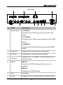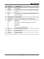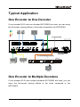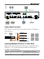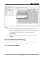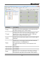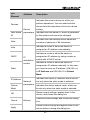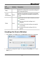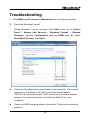
1
User Manual N143 N373 & N383 Presentation Switcher & H.264 Encoder and Decoder Version: V1.0.1 Important Safety Instructions Note: In case of any content change, we are sorry for no further notice. Warning: To reduce the risk of fire, electric shock or product damage: 1. Do not expose this apparatus to rain, moisture, dripping or splashing and that no objects 6. Clean this apparatus only with dry cloth. filled with liquids, such as vases, shall be placed on the apparatus. 2. Do not install or place this unit in a bookcase, built-in cabinet or in another confined space. 7. Unplug this apparatus during lightning storms or when unused for long Ensure the unit is well ventilated. periods of time. 3. To prevent risk of electric shock or fire hazard due to overheating, do not obstruct the unit’s ventilation openings with newspapers, tablecloths, curtains, and similar items. 8. Protect the power cord 4. Do not install near any heat sources such as radiators, heat registers, stoves, or other apparatus (including amplifiers) from being walked on or pinched particularly at plugs. 9. Only use attachments / accessories specified by the manufacturer. that produce heat. 5. Do not place sources of naked 10. Refer all servicing to flames, such as lighted candles, qualified service on the unit. personnel. Table of Contents Introduction .................................................................................................... 3 Overview................................................................................................... 3 N143 .................................................................................................. 3 N373 .................................................................................................. 4 N383 .................................................................................................. 4 Features ................................................................................................... 5 N143 .................................................................................................. 5 N373 .................................................................................................. 6 N383 .................................................................................................. 6 Package Contents .................................................................................... 8 N143 .................................................................................................. 8 N373 .................................................................................................. 8 N383 .................................................................................................. 8 Specifications ............................................................................................ 9 N143 .................................................................................................. 9 N373/N383 ...................................................................................... 11 Panel ...................................................................................................... 13 N143 ................................................................................................ 13 N373/N383 ...................................................................................... 15 Typical Application .................................................................................. 17 One Encoder to One Decoder ......................................................... 17 One Encoder to Multiple Decoders .................................................. 17 Multiple Encoders to Multiple Decoders .......................................... 18 Switching Inputs in One Encoder..................................................... 18 Video Wall Function ......................................................................... 19 Viewing Multiple Pictures in One Sink ............................................. 19 Hardware Installation................................................................................... 21 Operating with Control Software ................................................................ 23 1 Before Using the Control Software ......................................................... 23 Setting a Static IP on Your Computer .............................................. 23 Configuring Your Operating System Firewall ................................... 25 Control Software Instructions .................................................................. 26 Tool Bar in Control Software ............................................................ 26 Searching Devices........................................................................... 27 Device Parameter Settings .............................................................. 29 Device Settings Window Introduction .............................................. 31 TX Input Window Introduction.......................................................... 33 Matrix Setting Introduction ............................................................... 34 Creating the Scene Window ............................................................ 35 Scene Area Window Introduction..................................................... 36 IR Remote Control ........................................................................... 38 RS232 Remote Control ................................................................... 39 Configuration Files Management ..................................................... 40 Logs ................................................................................................. 42 Configuration Examples.......................................................................... 43 Switching Inputs in One Encoder..................................................... 43 Setting a Matrix................................................................................ 47 Setting a Video Wall ........................................................................ 52 Setting Video Wall Properties .......................................................... 61 Troubleshooting ........................................................................................... 63 Product Service ........................................................................................... 65 Maintenance ........................................................................................... 65 Provided Service..................................................................................... 65 Mail-In Service ........................................................................................ 65 Warranty ................................................................................................. 66 Warranty Limits and Exclusions .............................................................. 66 Glossary ....................................................................................................... 68 2 Introduction Overview N143 N143, delivering media over IP networks, is a high performance live H.264 streaming media encoder. N143 is also a switcher with eight inputs and three outputs. N143 features four HDMI inputs, two CVBS inputs, two VGA inputs, one HDMI output, one VGA output and one Ethernet output. In addition, N143 supports four stereo audio inputs respectively associated to the VAG 1, VGA 2, CVBS 1 and CVBS 2 inputs, six microphone inputs and one stereo output extracted from the HDMI output. N143 can be used with decoders N373 and N383 to provide complete end-to-end streaming media system. N143 adopts standard H.264/MPEG-4 AVC encoding and outputs two IP streams, a stream from 480p@60 to 1920x1200@60 and a 480p@60 stream. N143 outputs resolutions from 480p@60 to 1920x1200@60 scaled based on the sink EDID. High performance signal processing scales and optimizes video input signals to obtain the intended viewing effects. Encoding controls can also adjust bit rate and quality. N143 expands Audio/Video system capability by extending the Audio/Video signals over IP networks. 3 N373 N373 is a high performance live H.264 decoder used with N143 encoder to provide complete end-to-end streaming-media transmission system. N373 supports video wall function. In addition, it supports streaming resolutions and refresh rates up to 1920x1200@60. The output resolutions range from 480p@60 to 1920x1200@60 scaled based on the sink EDID. With the computer control software, this compact decoder offers multiple integrated features, such as RS232, IR for flexible control and management options. N383 N383 is a high performance live H.264 decoder used with N143 encoder to provide complete end-to-end streaming-media transmission system. N383 can decode up to 16 IP streams. When N383 receives a single IP stream, it has the same decoding features as N373's, such as supporting streaming resolutions and refresh rates from 480p@60 to 1920x1200@60 and output resolutions from 480p@60 to 1920x1200@60 scaled based on the sink EDID. When receiving two or more IP streams (up to 16 IP streams), it supports streaming resolutions and refresh rates up to 480p@60 and output resolutions from 480p@60 to 1920x1200@60 scaled based on the sink EDID. With the computer control software, this compact decoder offers multiple integrated features, such as RS232, IR for flexible control and management options. 4 Features N143 Allows up to eight inputs be switched to three audio or video outputs. Supports four stereo audio inputs corresponding to the VAG 1, VGA 2, CVBS 1 and CVBS 2 inputs, six microphone inputs and one stereo output extracted from the HDMI output. Streams HDMI signals over IP networks Supports H.264/MPEG-4 AVC compression standard. Use with H.264 decoder N373 to provide features, such as video wall function, extending HDMI signals over IP networks, matrix switching control over LAN. Use with H.264 decoder N383 to provide multi-picture viewing effects (up to 16 pictures) in a single screen in addition to the same features as N373. Supports the HDMI input resolution up to 1080p. Outputs two IP streams, a stream from 480p@60 to 1920x1200@60 and a 480p@60 stream. Supports output resolutions from 480p@60 to 1920x1200@60 scaled based on the sink EDID. Scales and optimizes video input signals for the intended viewing effects. Auto input format detection to provide the appropriate decoding and signal processing. Encoding bit rate is selectable from 1K~40Mbps. Supports TCP/IP, Telnet, UDP, IGMP and H.264 Supports AutoIP configuration. Automatically detected by the control software. 5 Uses with the IP control box TK-N006-000 for matrix control and management via LAN. N373 Supports live IP video stream decoding. Uses with encoder N143 to provide a complete end-to-end stream transmission system, supporting seamless switching. Supports streaming resolutions and refresh rates from 480p@60 to 1920x1200@60. Supports output resolutions from 480p@60 up to 1920x1200@60 based on the sink EDID. Supports video wall function IR pass-through control for sources or sinks over IP networks. RS232 for debug or to control a RS232 device. Automatic aspect ratio filling, following and fitting management. Support TCP/IP, Telnet, UDP, IGMP and H.264 Supports PoE Supports AutoIP configuration. Automatically detected by control software. Uses with the IP control box TK-N006-000 for matrix control and management via LAN. N383 Supports live IP video stream decoding Uses with encoder N143 to provide complete stream transmission system, supporting seamless switching. Supports streaming resolutions and refresh rates from 480p@60 to 1920x1200@60. 6 Supports output resolutions from 480p@60 to 1920x1200@60 based on the sink EDID. Supports multi-picture viewing effects in a single screen by automatically dividing the screen into 1, 4, 9 or 16 complete pictures based on the number of IP streams. IR pass-through control for sources or sinks over IP networks. RS232 for debug or to control a RS232 device. Automatic aspect ratio filling, following and fitting management. Support TCP/IP, Telnet, UDP, IGMP and H.264 Supports PoE Supports AutoIP configuration. Automatically detected by control software. Uses with the IP control box TK-N006-000 for matrix control and management via LAN. 7 Package Contents N143 1 x N143 1 x Power cable 1 x Phoenix male connector (3.5 mm 3 pins) 2 x Mounting ear N373 1 x N373 1 x Power cable 1 x Power adapter 1 x Phoenix male connector (3.5 mm 3 pins) 1 x Phoenix male connector (3.5 mm 5 pins) 2 x Mounting ear N383 1 x N383 1 x Power cable 1 x Power adapter 1 x Phoenix male connector (3.5 mm 3 pins) 1 x Phoenix male connector (3.5 mm 5 pins) 2 x Mounting ear 8 Specifications N143 Technical 4 × HDMI IN 2 x VGA IN 2 x CVBS IN I/O Connections 1×HDMI OUT 1x VGA OUT 1× RJ45 2 × RS232 (3.5mm phoenix) Power Supply AC 100~240V 50/60Hz Power Consumption 20 Watts Input Video Signal 1.2 volts p-p Input DDC Signal 5 volts p-p (TTL) Data Rate 1K~40Mbps, configurable Maximum Distance 100 meters Input: HDMI: 480i, 480p, 576i, 576p, 720p,1080i, 1080p Video Supported Format VGA: 640x480@60, 800x600@60, 1024x768@60, 1280x720@60, 1280x768@60, 1280x800@60, 1280x1024@60, 1360x768@60, 1400x1050@60, 1440x900@60, 1600x1200@60, 1680x1050@60, 1920x1080@60, 1920x1200@60 9 Technical CVBS: 480i@NTSC Output: HDMI: 480p@60~1920x1200@60 scaled based on the sink EDID. Output Video Control Method VGA: Follows the HDMI output. Ethernet: 480p@60~1920x1200@60 HDMI 1.3 RS232 LAN Human body model: ESD Protection ±8kV (air-gap discharge) ±4kV (contact discharge) Surge Protection Voltage: ±1kV Operating 32°F to 95°F (0°C to 35°C) Temperature 10% to 90%, non-condensing Storage Temperature -4°F to 140°F (-20°C to 70°C) 10% to 90%, non-condensing HDMI equipped source devices and sinks, connected with HDMI cables. System Requirements CVBS equipped source devices, connected with CVBS cables. VGA equipped source devices and sinks, connected with VGA cables. Industry standard CAT5e/6 cables or above. A 10/100Base-T Ethernet switch or above. 10 General Case Dimensions 525 mm x 122 mm x 327 mm (W x H x D) 20.7'' x 4.8'' x 12.9'' Device Dimensions 440 mm x 88 mm x 211 mm (W x H x D) 17.3'' x 3.4'' x 8.3'' Mass (Main unit) 3.5 kg Certification CE, FCC, RoHS N373/N383 Technical 1 × RJ45 1 × AUDIO OUT (3.5mm phoenix) 1 × HDMI OUT 2 × RS232 (3.5mm phoenix) I/O Connections 1 × IR TX (3.5mm phoenix) 2 × IO/IN (3.5mm phoenix) 2 × RELAY (3.5mm phoenix) Power Supply 12V 2A DC, 5.5mm Power Consumption 4.56 Watts Input Video Signal 1.2 volts p-p Input DDC Signal 5 volts p-p (TTL) Maximum Distance 100 meters Input: Video Supported Format Ethernet: 480p@60~1920X1200@60 for N373, 480p@60 for N383. Output: HDMI: 480p@60~1920X1200@60 scaled based 11 Technical on the sink EDID. Output Video HDMI 1.3 Output Audio Stereo (reserved) Control Method RS232 LAN Human Body Model: ESD Protection ±8kV (air-gap discharge) ±4kV (contact discharge) Surge Protection Operating Temperature Storage Temperature Voltage: ±1k V 32°F to 95°F (0°C to 35°C) 10% to 90%, non-condensing -4°F to 140°F (-20°C to 70°C) 10% to 90%, non-condensing HDMI equipped sinks, connected with HDMI cables. System Requirements Industry standard CAT5e/6 cables or above. A 10/100Base-T Ethernet switch or above. Case Dimensions 390 mm x 92 mm x 220 mm (W x H x D) 15.4'' x 3.6'' x 8.7'' Device Dimensions 269 mm x 24 mm x 110 mm (W x H x D) 10.6'' x 0.9'' x 4.3'' Mass (Main unit) 0.78 kg Certification CE, FCC, RoHS General 12 Panel N143 Front Panel HDMI 1 HDMI 2 HDMI 3 HDMI 4 VGA 1 VGA 2 CVBS 1 CVBS 2 POWER WORK RESET 1 2 3 4 5 ID Name Description 1 Power Indicates the power status. indicator 2 Work Indicates the working status. indicator 3 4. Reset Presses and holds this button to restore the device to its button default settings. Button Lit when a button is selected. indicator 5 Selection Presses this button to select the input sources. button 13 Rear Panel 10 9 8 1 2 ID Name Description 1 Source input 2 x VGA IN: 7 3 4 5 6 Connects to the VGA source devices via the VGA cables. 2 x CVBS IN: Connects to the CVBS source devices via the CVBS cables. 4 x HDMI IN: Connects to the HDMI source devices via the HDMI cables. 2 HDMI OUT Connects to a HDMI sink via a HDMI cable. 3 VGA OUT Connects to a VGA sink via a VGA cable. 4 LAN port 5 RS232 Connects to a 10/100Base-T Ethernet switch with a CAT5e/6 cable. RS232-1: Connects to a RS232 debug device, such as a computer. RS232-2: Connects to a RS232 device. 6 GND Grounding. 7 Power Connects to the AC power supply via a power cable. 14 ID Name Description 8 STERO OUT 2 x STERO OUT: Connects to the audio receivers to extract audio from HDMI out. 9 6 x MIC IN: MIC IN Connects the microphones to input audio. 10 4 x STERO IN: STERO IN Connects the audio input devices corresponded to the VAG 1, VGA 2, CVBS 1 and CVBS 2 inputs. N373/N383 N373 and N383 have the same appearance. Front Panel 1 2 ID Name Description 1 Power On: N373/N383 is powered on. indicator Off: N373/N383 is powered off. Link Steady On: N143 and N373/N383 are linked to each indicator other. 2 Flashing: N143 and N373/N383 are not linked to each other. Rear Panel 1 2 3 4 5 6 15 7 8 9 ID Name Description 1 GND Grounding 2 Power Connects to a 12V/2A DC power supply via a power adapter. 3 LAN Connects to a 10/100Base-T Ethernet switch with a CAT5e/6 cable. 4 AUDIO OUT Reserved port. 5 HDMI OUT Connects to a HDMI sink via an HDMI cable. 6 RS232 RS232 1: Connects to a RS232 debug device, such as a computer. RS232 2: Connects to a RS232 device. 7 IR TX Connects to an IR emitter. 8 IO/IN Reserved ports. 9 Relay Reserved ports. 16 Typical Application One Encoder to One Decoder If one encoder N143 and one decoder N373/N383 are used, you can enjoy the full-screen viewing effects in the sinks connected to the N373/N383. One Encoder to Multiple Decoders If one encoder N143 and multiple decoders N373/N383 are used, you can enjoy the full-screen viewing effects in the sinks connected to the N373/N383. 17 L 1 R L 2 R L 3 R STERO IN L 4 R L 1 R L 2 R L 3 R L 4 R L 5 R L 6 R MIC IN STERO OU T1 STERO OU T2 3 4 Multiple Encoders to Multiple Decoders If multiple encoders N143s and decoders N373/N383 are used, you can: Enjoy the full-screen viewing effects in the sinks connected to the N373/N383 if one N143 is linked. Enjoy multi-picture viewing effects in the sinks connected to the N383s if multiple N143s are linked. L 1 R L 2 R L 3 R L 4 R L 1 R L 2 R STERO IN L 3 R L 4 R L 5 R L 6 R STERO OU T 1 STERO OU T2 MIC IN 3 L 1 R L 2 R L 3 R L 4 R L 1 R L 2 R STERO IN L 3 R L 4 R 4 L 5 R L 6 R STERO OU T 1 STEROTOU 2 MIC IN 3 L 1 R L 2 R L 3 R L 4 R L 1 R L 2 R STERO IN L 3 R L 4 R 4 L 5 R L 6 R STERO OU T 1 STERO OU T2 MIC IN 3 L 1 R L 2 R L 3 R STERO IN L 4 R L 1 R L 2 R L 3 R L 4 R L 5 R 4 L 6 R STERO OU T 1 STERO OU T2 MIC IN 3 4 Switching Inputs in One Encoder With one encoder N143, you can switch between the four source devices to enjoy the viewing effects in the sinks connected through HDMI or VGA ports. 18 Video Wall Function N373 supports video wall function in the single host mode. The diagram is shown as follows. Viewing Multiple Pictures in One Sink Based on the number of IP streams from the sources, a single screen can be divided into 1, 4, 9 or 16 parts with each part displays a complete picture. For details, see the following table. Decoder N383 Number of N143 linked Viewing effects on the screen 1 complete picture filling the entire 1 19 Decoder Number of N143 linked Viewing effects on the screen screen. 4 complete pictures filling the entire 2~4 screen 9 complete pictures filling the entire 5~9 screen. 16 complete pictures filling the 10~16 entire screen. Note: When the number of N143 linked to N383 is from 2~3, 5~8, or 10~15, the unoccupied parts of the screen show no picture. For example, N383 below is linked to one or two N143s, the sinks connected to N383s show one or two complete pictures. Two N143s Linked One N143 Linked 20 Hardware Installation Warnings: Before the installation, disconnect the power supplies from all the devices. During the installation, connect or disconnect the cables gently. 1. Connect one DVD player, one Apple TV and one TV to the N143 via two HDMI cables and one VGA cable. 2. Connect one TV to the N373 via a HDMI cable. 3. Connect one TV to the N383 via a HDMI cable. 4. Connect a computer, N143, N373, N383 to a 10/100Base-T Ethernet switch via CAT5e/6 cables. 5. Connect the devices to the power supplies and start the operations. Note: If the switch doesn’t support PoE function or is unable to provide enough power, connect N373 and N383 to the power supplies with their power adapters. 21 L 1 R L 2 R L 3 R STERO IN L 4 R L 1 R L 2 R L 3 R L 4 R L 5 R L 6 R MIC IN STERO OU T1 3 STERO OU T2 4 22 Operating with Control Software You can use HDMI over IP console control software to manage and control the connected devices. You just need to extract the provided compression file to your computer and double-click HDMIoverIPConsole.exe to start it without additional installation processing. This section takes HDMIoverIPConsoleV2.4.13 as an example. Before Using the Control Software Before using the control software, you need to set a static IP address on your computer and configure your operating system firewall to allow this software to communicate on your network. Note: The operation system must be Windows XP or a later version. Setting a Static IP on Your Computer Before using the control software, make sure that the IP address of your computer installed with this software and TX/RX are in the same network segment. By default, TX/RX uses AutoIP protocol, and their IP address is 169.254.X.X and subnet mask is 255.255.0.0. A computer running Windows 7 is used as an example to configure a static IP address. 1. Click Start menu, choose Control Panel > Network and Internet > Network and Sharing Center > Change Adapter Settings, right click Local Area Connection, and then choose Properties. 23 2. Double-click Internet Protocol Version 4 (TCP/IPv4). 3. Select Use the following IP address, after configuring the following settings in the provided example, and then click OK. IP address: 169.254.2.5 Subnet mask: 255.255.0.0 24 4. Click OK. Configuring Your Operating System Firewall Your operating system firewall may block some features of the control software to prevent it controlling TX and RX. A computer running Windows 7 is used as an example to configure your operating system firewall in two methods. Method 1: You can configure the firewall in the Windows Firewall panel on your computer. For more information, see HDIP Product FAQ. Method 2: You can also configure the firewall when starting the control software. Then, Windows Security Alert window may display. If so, select a network you allow this software to communicate on, for example, select both private and public networks. And then click Allow access (with Administration authority). 25 Control Software Instructions Tool Bar in Control Software You can click the icons in the tool bar to quickly configure the control software. 26 GUI Element Description Allows the user to import past saved devices and scene Import configuration file for easy setup and multiple same projects which require the same configuration. Export IR Allows the user to export the current devices and scene configuration file for easy recall and future setup. Allows the user to control the source or sink. Serial Schedule Allows the user to send commands to a RS232 device for device control and configuration. Allows the user to create a schedule for a configuration layout to run automatically at a specified time. Enables the device information window to notify the user Information this device’s alias, device type, host name and IP address. Enables the log information window to notify the user the software operation and device communication information, which can be used for troubleshooting. Log Note: It is recommended that you turn on the log only when necessary, such as use for troubleshooting. Help Notifies the user the information on the control software version. Searching Devices 1. Double-click HDMIoverIPConsole.exe to launch the control software. Note: If Windows Security Alert window is displayed, see Configuring Your Operating System Firewall for solutions. 2. Click Search as shown below to start searching TX/RX. 27 Please wait until the search is completed, it may take a few seconds. All functions are disabled when the search is in progress. 3. When the search is completed the discovered devices are displayed in the Devices list. The devices will show active green circles 28 . Note: If the TX and RX devices have been set before by this control software, select Restore check box which will start searching the devices and automatically restore to the previous matrix configurations. If no devices are found, see Question 1 in Troubleshooting for solutions. Device Parameter Settings In the Devices list, right-click on a single or more devices, all the authorized operations are displayed in the shortcut menu. The following table describes how to set the device parameters. 29 Operation Config Description Configures the device parameters, such as device alias, IP address settings (Auto, DHCP, Static). Configures the video input and output parameters, such TX input as choosing a source type between VGA, CVBS and HDMI inputs, setting the bitrates, profile. Update Updates one or more device status, such as alias, type or hostname. Deletes one or more devices that have been searched Delete and listed below in the Devices list. To display the devices that you have searched, click Search. Turn On OSD Not available. Turn Off OSD Not available. Reset Restores one or more devices to their factory settings. This operation may take a few seconds. When reset is 30 Operation Description completed, the devices will become active again. It’s recommended that you click Delete to remove the original devices and click Search to display them again. Reset EDID Not available. Restarts a single or more devices that have been Restart searched and listed below in the Devices list. This operation may take a few seconds. When restart is completed, the devices will become active again. Device Settings Window Introduction In the Devices list, right-click on any device, and then choose Config to display Device Settings window. Or you can also double-click on any device to display this window. 31 GUI Element Attribute Description Indicates the current device on which you perform operations. You can select another Devices device from this drop down list box for device Device Host Name parameters ID setting. Indicates the host name ID, which is generated by the system and cannot be changed. Indicates the user-defined device name that Alias contains a maximum of 80 characters. Indicates a mode in which the device is Auto assigned an IP address automatically. Indicates a mode in which the device is DHCP IP distribution modes assigned an IP address by using a router or switch with a DHCP server. Indicates a mode in which the device is assigned an IP address manually. In this case, you need to enter an IP address (169.254.x.x) Static in IP Address and 255.255.0.0 in Subnet Mask. IP Address Subnet Indicates the device IP address, which can be Network parameters Mask Apply Indicates the device subnet mask, which can be set only when the static mode is selected. Saves current settings, applies them to the OK Cancel set only when the static mode is selected. device, and closes this dialog box. Buttons Cancels current settings and closes this dialog box. Saves current settings and applies them to the device without closing this dialog box. 32 Note: If any changes are made to the IP distribution modes, for example it is changed from Static to Auto or DHCP, restart the device and search it again in the control software. TX Input Window Introduction GUI Element Attribute Description VGA IN 1, Video Input CVBS IN 1, Chooses a source type between VGA, HDMI IN 1, CVBS and HDMI inputs. HDMI IN 2 Bitrate Sets the bitrates of video input from 1~40000Kbps. Profile Sets the profile of video input, such as hp, 33 GUI Element Attribute Description mp, bp. Main Output Video Output Force Resolution Not available. Not available. Matrix Setting Introduction On the home screen of the control software, the Scene area displays the status of all TX and RX connections. GUI Element Attribute Create Modify Remove Description Creates a new configuration scene. Buttons Modifies the current configuration scene. Deletes the current configuration scene. 34 GUI Element Attribute Applies the configuration connection settings to Apply Applied automatically Description the connected devices. Indicates that settings are applied immediately Option after you configure the intersection between TX and RX. Indicates that the matrix created by devices is restored. Indicates that matrix settings are in Status Icons progress. Indicates that matrix settings are applied successfully. Indicates that matrix settings fail to be applied. Creating the Scene Window 1. Click Create in the Scene area, the Add Scene dialog box is displayed. 2. Change the configuration layout, for example setting Name to 3 x 3 and Size to 3 x 3. 35 3. Click OK. Note: To modify the current configuration layout, click Modify on the tool bar. Scene Area Window Introduction You can right click a cell in the Scene area to perform the operations from the shortcut menu. 36 GUI Element Change TX Change RX Remove TX Remove RX Description Selects which TX for a source to be displayed from the searched devices. Selects which RX for a sink to output image from the searched devices. Deletes the TX from the searched devices in the devices column. Deletes the RX from the search devices in the devices column. Selects all the cells in the Scene area to Select All combine them to enable the video wall mode, select or delete a TX for all RX. Remove All Combine Split Video Wall Properties Removes all the devices in the current Scene area. Combines all the cells to enable the video wall mode after all are selected. Cancels the combine function to re-enable the matrix mode and have each monitor single. Configures the video wall properties after it’s enabled. Turn OSD On Not available. Turn OSD Off Not available. Sends IR commands to control the source Remote control devices or sinks using the IR library built in the control software from your computer. Sends commands to a RS232 device connected Serial to N143 or N373/N383 for device configuration and control. 37 Tips: You can also click and drag the desired TX and RX from the Devices list to cells in the Scene area and apply the configuration connection settings. To select multiple cells, press and hold Ctrl while clicking the desired cells. To quickly configure multiple consecutive cells, hold the right mouse button and drag to select the cells to display the shortcut menu to perform the operations. IR Remote Control The TX/RX has an IR library built in the control software which allows the user to easily send IR commands to control source devices or sinks from your computer. To perform this operation, click IR in the tool bar and follow the on-screen instructions. 38 RS232 Remote Control The control software allows the user to easily send RS232 commands to a RS232 device for device configuration and control. To perform this operation, click Serial in the tool bar and follow the on-screen instructions. 39 Configuration Files Management When the control software is closed, the Windows operating system would save the configuration file project.hoi to the working directory of current user. Viewing the Default Configuration File Directory You can view the default directory from the Import dialog box displayed by clicking Import on the tool bar. 40 When running the control software next time, it would automatically read the configuration file project.hoi. Do not modify or delete the project.hoi. Otherwise, errors may be encountered during program running. Export or Import the Configuration File On the home screen of the control software, you can: Click Export on the tool bar to save the current devices and scene configuration file to a specified directory. Click Import on the tool bar to import the saved configuration file from this directory. 41 Logs The logs have recorded the software operation and device communication information, which can be used for troubleshooting. To view the logs, click Log in the tool bar. 42 Configuration Examples Switching Inputs in One Encoder N143 allows up to two HDMI inputs, one VGA input, 1 CVBS input to be switched to one HDMI and one VGA outputs. To perform this operation, do as follows. Preparations One N143 Four HDMI source devices Two sinks Two computers One CAT5e/6 cable, three HDMI cables, two VGA cables and one CVBS cable. Hardware Connection 1. Connect one DVD player, one computer, two Apple TVs to the N143 via two HDMI cables, one CVBS cable and one VGA cable. 43 2. Connect two TVs to the N143 via one HDMI cable and one VGA cable. 3. Connect your computer installed with the control software to the N143 with a CAT5e/6 cable. 4. Connect all the devices to the power supplies and power them on. PC with Control Software Operation 1. Double-click HDMIoverIPConsole.exe to launch the control software; Click Search as shown below to start searching TX/RX, and one MX153 (N143) is found. 44 2. Right click MX153 to display the shortcut menu. 45 3. Choose TX Input to display Select TX Input dialog box. 4. Select a source type between HDMI, VGA and CVBS inputs; Set the bitrates; Set a profile. Note: We would recommend that you keep the bitrate and profile as default values. 5. Click OK. 46 Setting a Matrix You can set a matrix through the control software to control and manage all the connected devices in a network. This section takes a 2 x 2 matrix as an example. Preparations Four encoder N143s Two decoders N373s and two decoders N383s One 10/100Base-T Ethernet switch. Four HDMI source devices Four sinks One computer installed with the control software Eight HDMI cables and nine CAT5e/6 cables Hardware Connection 1. Connect one DVD player, one Xbox, two Apple TVs to four N143s via four HDMI cables. 2. Connect the N143s to the 10/100Base-T Ethernet switch with four CAT5e/6 cables. 3. Connect four TVs to the N373s and N383s via four HDMI cables. 4. Connect the N373s and N383s to the switch with four CAT5/6 cables. 5. Connect your computer to the switch with a CAT5e/6 cable. 6. Connect all the devices to the power supplies and power them on. Note: If the switch doesn’t support PoE function, connect the N373s and N383s to the power supplies. 47 L 1 R L 2 R L 3 R L 4 R L 1 R L 2 R L 4 R L 3 R L 6 R L 5 R MIC IN STERO IN 2 STEROTOU 1 STEROTOU 4 3 L 1 R L 2 R L 3 R L 4 R L 1 R L 2 R STERO IN L 4 R L 3 R L 6 R L 5 R MIC IN 2 STERO T OU 1 STEROTOU 3 L 1 R L 2 R L 3 R L 4 R L 1 R L 2 R STERO IN L 3 R L 4 R 4 L 5 R L 6 R MIC IN 2 STEROTOU 1 STEROTOU 4 3 L 1 R L 2 R L 3 R STERO IN L 4 R L 1 R L 2 R L 3 R L 4 R L 5 R L 6 R MIC IN 2 STEROTOU 1 STEROTOU 3 4 Operation 1. Double-click HDMIoverIPConsole.exe to launch the control software; Click Search as shown below to start searching TX/RX, and four MX153s (N143), two EX373s (N373) and two EX383s (N383) are found. 48 2. Click Create to create a 2 x 2 configuration scene. 3. Click OK, a 2 x 2 configuration scene is created as shown below. 49 4. Configure the intersection between TX and RX in different cells in the Scene area. 1) Right click the first cell, choose Change RX and then RX383-1. 2) Right click the first cell, choose Change TX and then MX153-1. 50 3) Repeat the above steps to select MX153-2, MX153-3, MX153-4 for EX383-1 to configure the intersection between TX and RX in the first cell. And click Apply to make the changes to TX and RX take effect. 51 4) Configure the intersection between TX and RX in other cells in the same way. The final scene is created as below. Then you can see the sinks connected to N373s show a complete picture filling the screen, the sinks connected to N383s show multiple complete pictures with the unoccupied parts shows nothing. Note: If N383 is linked to a single N143, the sink will show a complete After a 2 x 2 matrix is created, you can change TX and RX using picture filling the screen as that connected to N373. the control software to enjoy different viewing effects. In addition, you can also switch between different sources in a certain N143, if it is connected to multiple sources via HDMI, VGA or CVBS ports. Setting a Video Wall N373 supports the video wall function in the single host mode. You can combine multiple cells of N373s to show the same video source. This section 52 takes a 2 x 2 configuration scene as an example. Preparation: One encoder N143 Four decoders N373s One 10/100Base-T Ethernet switch. One HDMI source device Four sinks One computer installed with the control software Five HDMI cables and six CAT5e/6 cables Hardware Connection 1. Connect one DVD player to the N143 via a HDMI cable. 2. Connect the N143 to the 10/100Base-T Ethernet switch with a CAT5e/6 cable. 3. Connect four TVs to the N373s via four HDMI cables. 4. Connect the N373s to the switch with four CAT5/6 cables. 5. Connect your computer to the switch with a CAT5e/6 cable. 6. Connect all the devices to the power supplies and power them on. Note: If the switch doesn’t support PoE function, please remember to plug in the power adapters of Transmitters/Receivers Operation 1. Double-click HDMIoverIPConsole.exe to launch the control software; Click Search as shown below to start searching TX/RX, and one MX153 53 (N143) and four EX373s (N373) are found. 2. Click Create to create a 2 x 2 configuration scene. And click OK, a 2 x 2 configuration scene is created as shown below. 54 3. Configure the intersection between TX and RX in different cells in the Scene area. 55 1) Right click the first cell, choose Change RX and then EX373-1. 2) Right click the first cell, choose Change TX and then MX153-1. 56 3) Repeat the above steps to select MX153-1 for EX373-2, EX373-3, EX373-4 respectively in the other cells. And click Apply to make the changes to TX and RX take effect. The final scene is created as below. 4. Right click on any cell, and choose Select All (or press Ctrl+A) to select all the cells. 57 5. Right click on any cell and choose Combine to display the Video Wall Properties window. 58 6. Create a name, such as 2 x 2, for the video wall. 7. Enter the measurements of the sink Bezel and Gap Compensation. By default, keep the OW, OH, VW, VH values unchanged. And then click OK. 59 Note: It is recommended that you use the sinks with the same size for the intended viewing effects. GUI Element Description OW Indicates outside width of the sink in mm OH Indicates outside height of the sink in mm VW Indicates inside width of the sink in mm VH Indicates inside height of the sink in mm 8. Click Apply to make the video wall settings take effect. The video wall is configured successfully as shown below. You can identify the video wall is created in the control software by the double green lines across this 2 x 2 configuration scene. Note: You can easily right click on the video wall created and choose Change TX, this will allow simple switching of any of the searched TX in the listed devices to be displayed across the video wall. 60 Setting Video Wall Properties The control software provides the basic and advanced settings for video wall. You can configure the settings on all the sinks simultaneously or precisely set on each sink to perform the correct configuration and outcome for any project. Basic Settings You can right click the video wall created and choose Video Wall Properties, the Video Wall Properties window is displayed. Then click Basic Settings tab, this will allow you to simultaneously configure the settings on all the sinks. Note: We would recommend you leave the settings as default values. GUI Element Description Name Indicates the name of the video wall. OW Indicates outside width of the sink in mm 61 GUI Element Description OH Indicates outside height of the sink in mm VW Indicates inside width of the sink in mm VH Indicates inside height of the sink in mm Advanced Settings Click Advanced Settings tab, this will allow you to precisely configure the settings on each sink. Note: We would recommend you leave the settings as default values. 62 Troubleshooting 1. Why HDMI over IP console or Maintaintool cannot find any devices? • Check the Windows Firewall. Taking Windows 7 as an example: Click Start menu, go to Control Panel > System and Security > Windows Firewall > Allowed Programs, highlight Configuration tool for HDMI over IP, check Home/Work (Private) and Public. Check the IP address and subnet mask of your computer. The network segment for IP address is 169.254.x.x and the subnet mask is 255.255.0.0, the computer and TX/RX should be in the same network segment. For more information, see Setting a Static IP on Your Computer. Check the IGMP snooping status in the switch. This function should be enabled. 63 2. Why TV shows no picture with RX connected? Check that power supplies of all the devices are powered on. Check that all the cables are qualified and connected properly. Check that the sink works properly, and that source devices have normal signals output. Check that the output resolutions of the source devices are supported by TX, which supports the following input resolutions. TX port type Supported input resolutions of TX HDMI 480i, 480p, 576i, 576p, 720p, 1080i, 1080p VGA 640x480@60, 800x600@60, 1024x768@60, 1280x720@60, 1280x768@60, 1280x800@60, 1280x1024@60, 1360x768@60, 1400x1050@60, 1440x900@60, 1600x1200@60, 1680x1050@60, 1920x1080@60, 1920x1200@60 CVBS 480i@NTSC Check that TX has been switched to the right source type connected via the HDMI, VGA or CVBS ports. Check that TX and RX are linked based on status of the Link indicators on RX. For details, see description in Panel. If link exceptions exist, link TX and RX using the control software on your computer. Check that your sink is switched to the correct source input mode, such as switching to HDMI 1 if HDMI 1 interface is connected to the RX via a HDMI cable. Check that no compatibility issues exist between RX and sink. If so, replace the sink with other models. Check that power supplies of all the devices are powered on. The switch supports IGMP snooping and this function is enabled. Note: For more information, see HDIP Product FAQ. 64 Product Service Maintenance Clean this unit with a soft, dry cloth. Never use alcohol, paint thinner or benzine to clean this unit. Provided Service 1. Damage Requiring service: The unit should be serviced by qualified service personnel if: The DC power supply cord or AC adapter has been damaged; Objects or liquids have gotten into the unit; The unit has been exposed to rain; The unit does not operate normally or exhibits a marked change in performance; The unit has been dropped or the cabinet damaged. 2. Servicing Personnel: Do not attempt to service the unit beyond that described in these operating instructions. Refer all other servicing to authorized servicing personnel. 3. Replacement parts: When parts need replacing ensure the service uses parts specified by the manufacturer or parts that have the same characteristics as the original parts. Unauthorized substitutes may result in fire, electric shock, or other hazards. 4. Safety check: After repairs or service, ask the service to perform safety checks to confirm that the unit is in proper working condition. Mail-In Service When shipping the unit, carefully pack and send it prepaid, adequately insured and preferably in the original carton. Include a letter detailing the complaint and provide a daytime phone and/or email address where you can 65 be reached. If repair is needed during the limited warranty period the purchaser will be required to furnish a sales receipt/proof of purchase indicating date of purchase, amount paid and place of purchase. Customer will be charged for the repair of any unit received without such proof of purchase. Warranty If your product does not work properly because of a defect in materials or workmanship, Grandbeing Company (referred to as “the warrantor”) will, for the length of the period indicated as below, (Parts (1) Year, Labor(90) Days)which starts with the date of original purchase (“Limited Warranty period”), at its option either (a) repair your product with new or refurbished parts, or (b) replace it with a new or a refurbished product. The decision to repair or replace will be made by the warrantor. During the “Labor” Limited Warranty period there will be no charge for labor. During the “Parts” warranty period, there will be no charge for parts. You must mail-in your product during the warranty period. This Limited Warranty is extended only to the original purchaser and only covers product purchased as new. A purchase receipt or other proof of original purchase date is required for Limited Warranty service. Warranty Limits and Exclusions 1. This Limited Warranty ONLY COVERS failures due to defects in materials or workmanship, and DOES NOT COVER normal wear and tear or cosmetic damage. The Limited Warranty ALSO DOES NOT COVER damages which occurred in shipment, or failures which are caused by products not supplied by the warrantor, or failures which result from accidents, misuse, abuse, neglect, mishandling, misapplication, alteration, faulty installation, set-up adjustments, maladjustment of consumer controls, improper maintenance, power line surge, lightning damage, modification, or service by anyone other than a Factory Service 66 Center or other Authorized Service, or damage that is attributable to acts of God. 2. There are no express warranties except as listed under “limited warranty coverage”. The warrantor is not liable for incidental or consequential damages resulting from the use of this product, or arising out of any breach of this warranty. (As examples, this excludes damages for lost time, cost of having someone remove or re-install an installed unit if applicable, travel to and from the service location, loss of or damage to media or images, data or other recorded content. The items listed are not exclusive, but are for illustration only.) 3. Parts and service, which are not covered by this limited warranty, are your responsibility. 67 Glossary Acronym Complete Term AC Alternating Current BP Baseline Profile CVBS Composite Video Broadcast Signal DHCP Dynamic Host Configuration Protocol EDID Extended Display Identification Data HDMI High Definition Multimedia Interface HP High Profile IR Infra-red LAN Local Area Networks MP Main Profile OSD On Screen Display PoE Power over Ethernet RX Receiver TX Transmitter VGA Video Graphics Array 68 Grandbeing Technology Co., Ltd. Address: B-301, Science and Technology Building Phase11, 1057 Nanhai Rd, Nanshan District, Shenzhen, P.P.China Tel: 86-755-21620566 Post Code: 518067 www.grandbeing.biz Fax: +86 755-21620564