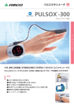
1
OXYGEN SATURATION MONITOR PULSOX -300i ® Instruction Manual This instrument must be used according to the instructions of the doctor. Safety Symbols Warnings and precautions noted in this manual and the instrument are indicated by the following markings, designed to prevent accidents caused by erroneous handling of the equipment. This indicates text consisting of a warning or precaution relating to safety. Please read the text carefully and use the equipment safely. This indicates an action which is prohibited. The prohibited action should never be carried out, under any circumstances. This indicates instructions concerning an action. Always follow the instructions carefully. This indicates an action which is prohibited. Never disassemble the product or unit. This symbol indicates that has no alarm function is prescribed in IEC60417-5319. This symbol indicates type BF equipment. The instrument provide a particular degree of protection against electric shock, particularly the leakage current and reliability of the protective earth connection with an F-TYPE APPLIED PART. F-TYPE APPLIED PART indicates applied part isolated from all other parts of the instrument to such a degree that the patient leakage current allowable in single fault condition is not exceeded when a voltage equal to 1.1 times the highest rated mains voltage is applied between the applied part and earth. This symbol indicates D.C. Authorized Standards For North America UL, C_ UL: WITH RESPECT TO ELECTRIC SHOCK, FIRE AND MECHANICAL HAZARDS ONLY IN ACCORDANCE WITH UL 60601-1, CAN/CSA C22.2 No.601.1 For Europe CE (Medical Device Directive): This instrument complies with EN60601-1, EN60601-1-2, EN14971, EN13485. Foreword Safety Precautions To ensure correct use of this instrument, read the following points carefully and adhere to them. After you have read this manual, keep it in a safe place where it can be referred to anytime a question arises. WARNING (Failure to adhere to the following points may result in death or serious injury.) The instrument is designed for measurement of the oxygen saturation (SpO2) of arterial blood and the pulse rate. Do not use it for any other purposes, such as warning of sleep apnea and breathing abnormalities. Do not use the instrument in places where flammable or combustible gases (anesthetic gas etc.) are present. Doing so may cause a fire. Do not disassemble or modify the instrument and accessories. Doing so may cause a fire or electric shock. The instrument should not be operated if it is damaged, or smoke or odd smells occur. Doing so may result in a fire. In such situations, turn OFF the power immediately, remove the battery, and contact the nearest authorized service facility. Do not put the batteries on a fire, short-circuit them, heat them or disassemble them. Doing so may cause explosion or heat generation, resulting in fire or injury. 1 Foreword CAUTION (Failure to adhere to the following points may result in injury or damage to the instrument or other property.) Do not use batteries other than those specified by KONICA MINOLTA SENSING, INC. When installing batteries in the instrument, make sure that they are correctly oriented according to the mark. If alkali fluid from the battery comes in contact with eyes, skin, or clothing, immediately wash the affected area and see a physician for treatment. Do not use probes other than those specified by KONICA MINOLTA SENSING, INC. Use of alternative probes may cause the probe to overheat, resulting in burns. Do not operate the instrument for long periods of time with a probe attached to a patient. Lowtemperature burn, redness or rash may result. If you feel pain or itchiness, stop use of the instrument immediately and consult a doctor. A doctor should also be consulted before using the instrument on patients with high fever, those with peripheral blood circulation problems or those with sensitive skins. When attaching the probe to a patient for use during sleep, care must be taken to avoid the cable from becoming twisted around the neck of the patient, for instance when he/she turns over. 2 Foreword Contents Safety Symbols Safety Precautions .............................................................1 Foreword ............................................................................4 Safety Notes .......................................................................... 4 Package Contents ................................................................. 5 About Probe ........................................................................... 5 System Diagrams and Accessories ....................................... 6 Names of Parts ...................................................................... 7 Notes on Use ......................................................................... 8 Notes on Storage ................................................................. 10 Disposal Method ...................................................................11 Preparations .....................................................................12 1) Attaching the Wrist Band ................................................. 12 2) Connecting the probe ...................................................... 14 3) Installing the battery ........................................................ 15 4) Attaching the PULSOX to the wrist .................................. 16 Measurement ...................................................................17 1) Starting the Measurement (Power ON) ........................... 17 2) Reading the display ......................................................... 19 3) Ending the Measurement (Power OFF) ........................... 20 About Auto Power-Off function............................................. 20 Regarding the memory function ........................................... 20 External Connection .........................................................21 Trouble Shootings ............................................................23 Error Messages ................................................................... 23 Check Points before repairing ............................................. 28 Maintenance and Inspection ................................................ 28 Cleaning ............................................................................... 28 Specification .....................................................................29 Appendix ..........................................................................31 Calculation Method for Displayed Values ............................ 31 EMC Guidance .................................................................... 32 Measurement Principle ........................................................ 34 Relation between Oxygen Saturation and partial Pressure .............. 35 3 Foreword Foreword Safety Notes CAUTION: Federal law restricts this device to sale by or on the order of a physician. The instrument is designed for measurement of the oxygen saturation (SpO 2 ) of arterial blood and the pulse rate. Do not use it for any other purposes, such as warning of sleep apnea and breathing abnormalities. The Oxygen Saturation Monitor PULSOX-300i is designed to measure oxygen saturation (SpO2 value) in arterial blood and pulse rate by attaching a probe to a peripheral part of the body, such as a finger, in a non-invasive method. PULSOX-300i is intended for continuous data-collection use such as during a sleep study and not for traditional continuous use. • The compact, lightweight and portable body has a large LCD for easy operation. • The LCD has a backlight function, providing high visibility even in dark areas. • Built-in memory enables storage of up to 300 hours of measured data. • Use of the optional software allows you to set the date/ time and to set the auto-power-off time on the PULSOX300i. In addition, the measured data stored in the memory can be processed, stored collectively or output via a printer using a personal computer. 4 Before using the instrument, make sure that the following items are present. 1) PULSOX-300i main body × 1 2) Wristband WB-300 × 1 3) AAA-size alkaline battery × 1 4) Instruction manuals • PULSOX-300i instruction manual × 1 • Separate manual (Using manual for Probes) × 1 ✻ The probe is optional. About Probe The following probe types can be used with this instrument. • Finger Clip Probe SR-5C • Spot Check Probe SP-5C • Monitor Probe LM-5C • Personal Probe SD-5C ◆ As shown in the table below, the measuring point varies with the probe used, so select the one that is suitable for your purpose. Probe type SR-5C SP-5C LM-5C SD-5C Patient Allowed measuring point Adult Finger (hand) ◆ For the usage method, please refer to “Connecting the probe” (page 14) on this manual and the probeʼs instruction manual. 5 Foreword Package Contents Foreword System Diagrams and Accessories The instrument consists of the following items. Standard accessories Optional accessories Optional accessories Finger Clip Probe SR-5C ����������� Extension cable EC-300 Spot Check Probe SP-5C Monitor Probe LM-5C USB adapter UA-300 Personal Probe SD-5C Standard accessories Wristband WB-300 AAA-size alkaline battery 6 Foreword Names of Parts Power button Used to start measurement (Power-ON) or end measurement (Power-OFF). PULSOX-300Xi LCD Display (with the backlight function) Measurement results and messages are displayed. Backlight button Press it to turn ON the backlight of the LCD. Probe connector Connect the probe or extension cable EC-300 to this connector. External output terminal Connect the optional USB adapter “UA-300” to connect the instrument to a personal computer. Battery cover The cover can be opened by turning it approximately 90 degrees. Wristband Used to set the instrument on your wrist. 7 Foreword Notes on Use • This instrument should be used under the following operating conditions. • Temperature of 0 to 40°C (32 to 104°F), relative humidity of 30 to 85%, with no condensation. • Atmospheric pressure of 700 to 1060 hPa (altitude of –400 to 3000m). • This is a precision instrument. To avoid the possibility of it being damaged, the instrument should not be dropped nor should heavy objects be placed on top of it. • Do not expose this instrument to rain and water. • This instrument has no alarm function. Do not use this instrument if an alarm function is necessary. • This instrument is designed for use on adults. When using the instrument on infants or babies, please note that the designed measurement accuracy cannot be guaranteed. • Do not use the instrument on a point where there is excessive vibration. In addition, to avoid excessive impact on the instrument, it should be handled gently. Failure to observe this may cause breakdown. • A maximum of 300 hours of measurement data can be stored, or the maximum storable number of data files is 399 files. If measurements are continued after the maximum number of storable data has been reached, the new data will overwrite the oldest data. To keep data, be sure to download it before the memory becomes full. • Accurate measurement data may not be obtained in the following cases. • When body movement is excessive • When the probe is not attached properly • When blood circulation at the measuring point is poor (due to pressure on arm/finger, peripheral circulatory insufficiency) • When ambient light (e.g. panel light, fluorescent light, infrared heat lamp, direct sunlight) is too strong 8 • • • • • When influenced electromagnetically by other electronic devices (e.g. near electrical appliances like TV, medial device) When a mobile telephone is used during measurement When influenced by abnormal hemoglobin like carbon monoxide hemoglobin (HbCO) and methemoglobin When pigments such as cardiogreen, intravascular dyes and indocyanine greenare present in the blood When finger nails are polished Tables 1 and 2 below show the errors which may occur due to these hemoglobins. Difference from the SaO2 value to displayed value <Table 1> <Table 2> HbCO Methemoglobin SaO2 SaO2 1% 5% 10% 1% 5% 10% -0.1 -0.7 -1.5 +0.2 +1.3 +3.2 50 50 70 70 -0.1 -0.7 -1.5 -0.6 -2.3 -3.2 90 90 -0.2 -0.8 -1.6 -1.5 -6.0 -9.6 100 -0.2 -0.8 -1.7 100 -1.8 -7.5 -12.2 Displayed value is sometimes Measured value is always lower than the actual value. higher than the actual value if SaO2 is around 50%. • Do not immerse the probe, the extension cable or the connecter of PULSOX-300i in disinfectant. Doing so may cause a malfunction. • When using the Extension Cable EC-300, fit and secure cables so they are not too loose or too tight. • Before connecting to a personal computer, remove the Pulsox from the patient. 9 Foreword • Foreword Notes on Storage • This instrument should be stored under the following storage conditions. • Temperature of –10 to 60°C (14 to 140°F), relative humidity of 10 to 95%, with no condensation. • Atmospheric pressure of 700 to 1060 hPa (altitude of –400 to 3000m). • When storing the instrument: • Do not store the instrument in an area where it will be exposed to water. • Do not store the instrument in an area where direct sunlight, pressure, temperature, humidity, ventilation, sunlight, dust, strong magnetic fields, and/or saline or sulphurous atmospheres may affect the instrument. • Do not store the instrument on an inclined surface or on a surface which may be subject to vibrations or physical shock. (Also avoid vibrations or physical shock during transportation.) • Do not store the instrument in areas where chemicals are stored or where gas may be emitted. • To avoid any problems occurring the next time the instrument is used, make sure the instrument, cords, probes and other accessories are cleaned and stored safely. • If the instrument will not be used for more than 2 weeks, remove the batteries from the battery to avoid the possibility of damage due to leakage of electrolyte. • The time/date set to the instrument using the optional software will be reset to the factory setting (Jan. 1, 2000/0:00) if the instrument is left for more than one day without the battery. • The measurement data and the auto power-off time set to the instrument using the optional software will be kept even if the instrument is left without the battery. 10 • When disposing of the used battery, insulate the polarity terminals with insulating tape etc. If the terminals of the battery come into contact with metal objects, heat generation, explosion or fire may result. • Make sure that the battery is either disposed of or recycled correctly in accordance with local laws and regulations. 11 Foreword Disposal Method Preparations Preparations Before starting measurements using this instrument, follow the procedure given below to ensure that measurements are stable. 1) Attaching the Wrist Band Attach the Wrist Band WB-300 (supplied as a standard accessory) to the instrument. Since the WB-300 is made of elastic material, it allows for flexibility and comfort of fitting on the wrist. 1 Place the instrument with its rear side up. 2 Pass the angled tip of the hook-and-loop tape of the wrist band outward through band fixture A. ◆ When doing so, make sure that the Velcro tape section faces upward. 12 hook-and-loop section Band fixture A Fold up the inserted hook-and-loop section, and stick it firmly to the band. 4 Pass the other end of the band outward through band fixture B. Preparations 3 Band fixture B ◆ Take care not to twist the band. 5 Fold back and secure the band with the hookand-loop tape section. ◆ When attaching the instrument to an arm, adjust the band length and fitting at this hookand-loop tape section. 13 2) Connecting the probe Preparations Connect the probeʼs connector plug into the Probe Connector on the instrument. ◆ Make sure that probeʼs connector plug is oriented correctly. ◆ Do not connect it in with excessive force. Doing so may damage the connector. ◆ Do not touch the connector terminals by hand. Contact failure may occur. <When using the Extension Cable EC-300> Connecting the extension cable EC-300 between the PULSOX-300i and the probe extends the probe cable to a total length of 1m. Extension Cable EC-300 (1m) 14 3) Installing the battery 2 Turn the battery cover clockwise approximately 90 degrees to open the cover. Preparations 1 ◆ When turning the c o v e r, k e e p t h e f l a t part of your finger on the coverʼs catch. This facilitates opening the cover with minimum force. Insert the battery into the battery compartment according to the polarity mark ( )shown on the rear of the instrument. ◆ This instrument requires one AAA-size battery. 3 Turn the battery cover counter-clockwise approximately 90 degrees to close it. ◆ Introduction of a new mechanism locks the cover automatically when it is closed. 15 4) Attaching the PULSOX to the Wrist Preparations 1 Remove the hook-andloop section of the band from the side with no probe connector. 2 Attach PULSOX-300i to the arm by inserting your hand through the Wrist Band. 3 Adjust the fastening position of the hook-andloop tape to adjust the tension of the Band. 16 Measurement 1) Starting the Measurement Connect the probe to the PULSOX-300i correctly. Press the Power button for a long time, the Power is ON, the backlight is ON, and all the elements on the display is displayed. ◆ After 30 seconds since the Power is ON, the Backlight is OFF automatically. ◆ Pulse wave mark will also be displayed in the pulse wave saving mode. 3 As shown the right, the setting date for today is displayed. ◆ By default, the date/time has been set to Jan. 1, 2000/0:00, and it is displayed in the order of “ʼ00”, “1 1” and “0-00”. The correct date/time can be set to the instrument using the optional software. Measurement 1 2 ➀Display the Year as A.D. ➁Display the Month and the Day month day ➂Display the Time as 24 hours format hour minute 17 4 Next, it will cause the file number of the next measurement to appear. ◆ The measurement data obtained from power-ON (start of measurement) up to power-OFF (end of measurement) will be stored in one file. Measurement 5 A file number is given to each set of measurement data (power-ON to power-OFF). (Maximum: 399 files) And, if the time for AutoPower-Off was set in the instrument, the setting time is displayed. ◆ The time for Auto-Power-Off is set by using the optional software. ◆ If the time for Auto-Power-Off has not been set, this step will be skipped and the measurement display will appear. 6 About 10 seconds after the Power is switched ON, measurements will be started and the measurement data at 1-second intervals will be stored in the memory of the PULSOX-300i. Pulse level meter is started to indicate but the measuring data is not displayed yet. ◆ “---” is displayed until the measuring data is calculated. <Regarding the measurement data> The measuring data is calculated and displayed, and the measurement is started. The measurement data includes the measurement values (SpO2 value, pulse rate, and error message information) and the file information (file number, date and time of start of measurements, and duration of measurement). 18 2) Reading the display When the instrument is turned ON, all the elements of the LCD will light up. The pulse level, pulse rate and SpO 2 value are displayed during measurement. Pulse rate (P.R.) Battery mark Pulse Level Meter Indicate the pulse level. ✻ For stable measurement, make sure that the pulse level meter lights up two or more segments by adjusting the measuring point or rubbing or warming it up to improve blood circulation. Oxygen saturation (SpO2) value If an error occurs, an error message mainly about SpO2 will be displayed. 19 Measurement Indicates the remaining battery capacity in three steps. If an error occurs, an error message mainly a b o u t P. R . w i l l b e displayed. 3) Ending the Measurement Press the Power button for a long time, the measurement is finished and the Power is off. Measurement About Auto-Power-Off function By connecting the instrument to a personal computer and using the optional software, the time to be elapsed from power-on (start of measurement) to power-off (end of measurement) can be set as the auto-power-off timer. If an auto-power-off timer is set, the measurement is finished automatically in the time after power-on. Regarding the memory function ● The memory built into the PULSOX-300i will continue to hold data even if the battery is removed. ● A maximum of 300 hours of measurement data can be stored; e.g., 10 hours of measurement data can be stored for 30 persons. Storage for measurement data is set up in 30-minute blocks, so even if the duration of measurement data is less than 30 minutes, it will be treated as a 30-minute block. For this reason, if measurement data with durations of shorter than 30 minutes are stored, the actual measurement duration will be different from the stored duration, and the maximum storable time will be shorter than 300 hours. ● The maximum storable number of data files is 399 files. After that, the No. 400 data file will be stored as data file No. 1, overwriting the previous No. 1 data file. 20 External Connection The PULSOX-300i has an external output terminal for outputting measurement data stored in the instrument's memory to a computer. In addition, when the Data Analyzing Software is installed on the computer and the PULSOX-300i is connected to the computer using UA-300, the date and/or Autopower-off timer (which cannot be set using only the instrument itself) can be set. It is also possible to download the measured data from the instrument's built-in memory to the computer to analyze the data, display data graphically, save data in spreadsheet format, or print data out. <Connecting the PULSOX-300i and a computer> PULSOX-300i UA-300 main unit UA cable USB cable Ext.Connect ● For details regarding the Data Analyzing Software, refer to the instruction manual and/or online help of the software. Computer ● For details regarding the connection between the PILSOX-300i and the computer, refer to the Installation Guide manual of the software. ● For details regarding the USB Adapter UA-300, refer to the instruction manual of the UA-300. 21 <Regarding the display in communication mode> ● When the PULSOX-300i is connected to a computer, the PULSOX-300i will enter UA communication mode automatically. In UA communication mode, the display will appear as shown below: This shows the PULSOX-300i is in UA communication mode. The instrument is connected to the computer with the UA-300. Ext.Connect This shows measured data is being downloaded to the computer. Do not remove the UA cable and/or USB cable from the PULSOX-300i and/or the computer. <Notes on communication mode> ● It is impossible to take measurements while the instrument is in communication mode. ● When removing the PULSOX-300i from the UA-300, the power of the instrument will be set to OFF automatically. 22 Trouble Shootings Error Messages The instrument display error messages when the error occurs. Check and correspond to them correctly. �������������� �� ����������� �������� �� ����������������������� ����������������������� �� ��������������������������������� ����������������������������� �� � � � � � � � � � � � � � � � � � � � � � � � ������������ �� ��������������������������� ���������������������� ��������� �� ������������������������ ������ ������������������� �� ��������������������������������� ������������������������ �� ���������������������������������� ����������������������������������� ��� �� ������������������������������������� ����������������������������������������� ������������������������������� �� ���������������������������������� ��������� �� �������������������������������� ����������������������������������� �� ������������������������������� ���������������������������������� �������������������������� ����������������������������� ������ 23 Check Points �� ����������� ����� �� � � � � � � � � � � � � � � � � � � �� � � � � � � � � � � � � � � � � � � � � � � � � � ����������������� �������������������������������� ������������������� ����������������������������� �������������������� ��������������������������������� ����������������� ����������������������������������� ������������ �� ������������������������������� �� � � � � � � � � � � � � � � � � � � � � � � ����������������������������� ������������������������ ���������������������������������� ��������������������� ������������������������������������ ����������������� ��������������������������������� ������������������������ �������������� ���������� �������������� �� ���������������������� ���������������������� �� ����������� ����� �������� Check Points �� ������������������������� ������������������������ ������������������� ��������������������� ������������������������ ���������������� ������������������� ����������������������� �� ��������������������������������� ������������������������ �� ���������������������������������� ����������������������������������� ��� �� ������������������������������������� ����������������������������������������� ������������������������������� �� ���������������������������������� ��������� �� �������������������������������� ����������������������������������� �� ������������������������������� ���������������������������������� �������������������������� ����������������������������������� �� �������������������������� ������������������� ��������������� �� ��������������������������������� ��������������������������������������� ������������������������������ ��������������������������������������� ����������������������������������� ������������������������������������ ��������������������������������������� ����������������������� �� �������������������������������������� ������������������������������������� ������������������������������������� ���������������������������������� ������������������ �� �������������������������� �� � � � � � � � � � � � � � � � � � � � � � � � � � � � � � ����������������������������������������� ��������������������������� ��������������������������������� ������������������������ ����������������������������������� ��������������� ��������������������������������� ��������������������� ��������������������������������� ������������������������ ���������������������������������������� ���������������� ������������������������������ ������������������� �� ���������������������� ��������������������� ������������������������������������� ���������������������� ��������������������������� ��������������������� �� ��������������������������������������� ������������������������������� ���������������������������������� �������������������������������������� ������������������������������������������ �������������������������������������� ���������������������������������� ��������� 24 �������������� ����� �� � � � � � � � � � � � � � � � � � � � � � � � � � � � � � ������������������������������� ������������������������������������ ������������������������������ ��������������������������� ��������������������������������� ������������������������������������� ������������������������������������ ��������������������������������� ��������� �� ������������������������������� ���������������������������������� �������������������������� ����������������������������������� �� ��������������� � ���������������������� ��������������������������� ���������������� ������������������� ��������������������� �� �������������������������������� ��������������������������������� ����������������������������������� ���������������������������� ��������������������������������� �������������������������������� ������������������������������������ ��������������������������� �� ����������� �� ���������������������� ���������������������� �������� �� ���������������������������� �������������������� �� ������������� 25 Check Points �� ��������������������������� �� �������������������������������� ������������������������� ���������������������������� ���������������������� ������������������������������ �������������� ����� �������� �� �������������������������� ���������������������������� ������������������ �� �������������������������������� ���������������������������� ����������������������������� ・� ������������������������� ��� � �������������������� ������������������������� ����������������������� �������������������������� ���������������������� ������������������� �� ������������������ ����������� ������� ������������������������������������� ������������������������������� ���������������� �� ������������� �� ����������� �� ��������������������������������� �� ����������������������������������� �������������������������������������� ・� ��������������������� �� ����������������� �������������� ������������� �� � � � � � � � � � � � � � � � � � � � � � � � � � � � ��������������������������������� ��������������������������������� �� ��������������������������������������� ����������������������������� ������������������ ・� ����������������������� �� ��������������������������������� �������������������� �� ��������������������������������������� ����������������������������� ������������������ Check Points �� � � � � � � � � � � � � � � � � ��������������������� �� � � � � � � � � � � � � � � � � ��������������������� ����� 26 �������������� ����� �������� �� ������������������������� �� �������������������������������� ������ ������������������������ �� ������������������������������� ������������������ ���������������������������������� ������������������������������� �������������������������������� ���������������������������������� ������������������� Check Points 27 Check Points before repairing Before taking any actions, check the following points first. ◆ If the abnormality continues to reappear, the instrument might be faulty, so contact the nearest distributor or authorized service facility. Problem · ����������� ������������� ������������� ���������� Checkpoint Solution Ref.Page · ����������������� ���������� · ����������������������� ������������������������������� ������������� P.15 · �������������������� ���������� · ��������������������������� ���������������������� . P.15 �� �������� · ���� ���������������� ��������������� ������������������� �������������� ������������������� ������������� ��������� �� ���������������������������� �������������������������������� ����������������������������� ������������������� P.20 Maintenance and Inspection Check Points • Before using the instrument, make sure that there is no damage to the instrument, no damage or wire-breakage in the probe cable and the instrument operates correctly and safely. Cleaning • Dampen a soft cloth with neutral detergent or water, wipe the instrument with it, then wipe off carefully with a dry cloth. In this way, make sure the instrument is cleaned and never use solvent. When cleaning, take care not to touch the connector terminals. Touching them may break terminal pins, resulting in breakdown or damage. 28 Specification Dual-wavelength pulse type (665nm/880nm) arterial blood oxygen saturation measuring instrument • Name: Oxygen Saturation Monitor • Model name: PULSOX-300i Functions: • Measuring range: SpO2: 0 to 100% SpO2 Pulse rate: 30 to 230 bpm • Accuracy: SpO2: ±2% SpO2 (70 to 100% range, 1S.D.) Pulse rate: ±2 bpm (30 to 100 range) or ±2% of value (100 to 230 range) ✻ PULSOX-300i has been clinically validated for use on adults. 0 to 40°C (32 to 104°F); 30 to 85% relative humidity with no condensation Atmospheric pressure/altitude range 700 to 1060hPa (altitude: –400 to 3000m) Storage conditions Temperature/humidity range –10 to 60°C (14 to 140°F); 10 to 95% relative humidity with no condensation Atmospheric pressure/altitude range 700 to 1060hPa (altitude: –400 to 3000m) Power 1 AAA-size battery: 1.5V 100mW (Service life under continual usage: approx. 30 hours with alkaline battery) Dimensions (W × H × D) 68 × 58 × 15 mm 29 Specifications Display Display type: Liquid crystal display (with back-light function) Oxygen saturation (SpO2) Pulse rate number Pulse level meter (8 steps) Battery indication (3 steps) Error messages indication Warning functions SpO2: Low SpO2 warning (flashing display) Battery indication Error message indication Memory function Up to 300 hours at one-second intervals SpO2 value, pulse rate, and error message information, and the file information (file number, date and time of starting measurements, and duration of measurement) ✻ Data can be downloaded or displayed using the optional software. Operating conditions Temperature/humidity range Weight 56g (including battery/excluding wrist band and probes) Usable life 6 years [Verified by KONICA MINOLTA SENSING, INC. (based on own data)] Probes (SR-5C, SP-5C, LM-5C, SD-5C) LED-SPD probe Type • Finger Clip Probe SR-5C • Spot Check Probe SP-5C • Monitor Probe LM-5C • Personal Probe SD-5C ✻ It can be used with one of Extension Cable EC-300 Components that touch the body Cover: Polycarbonate Wrist band: Polyethylene terephthalate, nylon 6 Rating nameplate: Polyethylene terephthalate Cover Wristband Rating nameplate Specifications Equipment classification (based on “UL 60601-1/EN 60601-1”) • Protection against electric shock: Internally powered • Type of applied part: BF • Not suitability for use in the presence of flammable anaesthetic mixture with air or oxygen or nitrous oxide. • The instrument is not protected against entry of water. • Only the cleaning method has been stipulated (no disinfection/sterilization methods have been stipulated). • Mode of operation of Equipment: Continuous while in Use (IEC 60601-1) 30 Appendix Calculation Method for Displayed Values <Pulse level meter> The pulse level meter displays the transmitted light amount ratio calculated by the following equation. The pulse level is indicated in eight levels (0 to 15%, full scale if over 10%). Transmitted light amount that varies due to the pulse Pulse level (%) = ------------------------------------------------------------------------------------------------------------------ x 100 Transmitted light amount that does not vary due to the pulse <Oxygen saturation (SpO2)> Updates the moving average of the oxygen saturation over the last 12 seconds at one-second intervals. <Pulse rate (P.R.)> Updates the moving average of the last 8 pulse rates at one-second intervals. Appendix 31 EMC Guidance Guidance and manufacture s declaration - electromagnetic emissions The Oxygen Saturation Monitor Model PULSOX-300i is intended for use in the electromagnetic environment specified below. The customer or the user of the Model PULSOX-300i should assure that it is used in such anenvironment. Emissions test Compliance Electriomagnetic environment - guidance Group 1 The Model PULSOX-300i uses RF energy only for its internal function. Therefore its RF emissions are very low and are not likely to cause any interference in nearby electromagnetic equipment. RF emissions CISPR 11 RF emissions Class B CISPR 11 Harmonic emissions Not applicable IEC61000-3-2 Voltage fluctuations/ flicker emissions The Model PULSOX-300i is suitable for use in all establishments, including domestic establishments and those directly connected to the public low-voltage power supply network that supplies buildings used for domestic purposes. Not applicable IEC61000-3-3 Guidance and manufacture s declaration - electromagnetic immunity The Oxygen Saturation Monitor Model PULSOX-300i is intended for use in the electromagnetic environment specified below. The customer or the user of the Model PULSOX-300i should assure that it is used in such anenvironment. Immunity test IEC 60601 Test level Compliance level Electromagnetic Discharge (ESD) 6 kV contact 8 kV air 6 kV contact 8 kV air Electrical fast Not applicable IEC61000-4-2 Transient/burst Electromagnetic environment guidance Floors should be wood, concrete or ceramic tile, if fllors are covered with synthetic materisl, the relative humidity should be at least 30%. IEC61000-4-4 Surge Not applicable Voltage dips, short Not applicable IEC61000-4-5 Interruptions and Voltage variations on power supply Input lines IEC61000-4-11 Appendix Power frequency (50/60Hz) magnetic field IEC61000-4-8 32 3 A/m 3 A/m Power frequency magnetic fields should be at level characteristic of a typical location in a typical commercial or hospital environment. Guidance and manufacture s declaration - electromagnetic immunity The Oxygen Saturation Monitor Model PULSOX-300i is intended for use in the electromagnetic environment specified below. The customer or the user of the Model PULSOX-300i should assure that it is used in such anenvironment. Immunity test Conducted RF IEC61000-4-6 Radiated RF IEC61000-4-3 IEC 60601 Test level Compliance level 3 Vrms 3 Vrms 3 V/m 3 V/m 150kHz to 80MHz 80MHz to 2.5GHz Electromagnetic environment guidance Portable and mobile RF communications equipment should be used no closer to any part of the PULSOX-300i, than the recommended separation distance calculated from the equation applicable to the frequency of the transmitter. Recommended separation distance ������������ � ���80MHz to 800MHz ������������ � 800MHz to 2.5GHz where P is the maximum output power rating of the transmitter in watts (W) according to the transmitter manufacturer and d is the recommended separation distance inmeters (m). Field strength from fixed RF transmitters, as determined by an electromagnetic site survey a, should be less than the compliance level in each frequency range b. Interference may occur in the vicinity of equipment marked with the following symbol: NOTE 1 At 80MHz and 800MHz, the higher frequency range applies. NOTE 2 These guidelines may not apply in all situations. Electromagnetic propagation is affected by absorption and reflection from structures, objects and people. a Field strengths from fixed transmitters, such as base stations for radio (cellular/cordless) telephone and land mobile radios, amateur radio, AM and FM radio broadcast and TV broadcast cannot be predicted theoretically with accuracy. To assess the electromagnetic environment due to fixed RF transmitters, an electromagnetic site survey should be considered. If the measured field strength in the location in which the PULSOX-300i is used exceeds the applicable RF compliance level above, the PULSOX-300i should be observed to verify normal operation. If abnormal performance is observed, additional measures may be necessary, such as reorienting or relocating the PULSOX-300i series. b Over the frequency range 150kHz to 80MHz, field strengths should be less than 3V/m. Appendix 33 Measurement Principle This instrument measures the oxygen saturation (SpO2) in arterial blood and pulse rate continuously in a non-invasive method by applying optical principles. With this instrument, SpO2 is defined by the following equation. SpO2= where C (Hb): C (HbO2): C(HbO2) C(HbO2) +C(Hb) 100 (% SpO2) Concentration of reduced hemoglobin Concentration of oxyhemoglobin The light-absorption characteristics of reduced hemoglobin (Hb) are very different from those of oxyhemoglobin. This instrument measures the changes in the absorption of red and infrared lights passing through the tissue to determine the SpO2 of the blood. Thus, this method is free from the effects of skin color, muscles, bones, and veins. Spectral Absorption of Hb and HbO2 Infrared light Absorption coefficient Red light Appendix Wavelength 34 Relation between Oxygen Saturation and Partial Pressure The relation between oxygen saturation (SpO 2) and oxygen partial pressure (PaO2) is shown in the graph below. SpO2 is the oxygen saturation as measured by pulse oximeters. Oxygen Saturation vs. Oxygen Partial Pressure % 100 90 85 80 70 60 50 40 SpO2 30 pH=7.4 37°C 20 10 0 10 20 30 40 50 60 70 PaO2 80 90 100 110 Torr (mmHg) 35 Appendix The curve of the above graph may shift to the right or left according to the pH of the blood or the body temperature. • Shift to right: acidosis, high body temperature • Shift to left: alkalosis, low body temperature MEMO Appendix 36 Manufacturer 3-91, Daisen-nishimachi, Sakai-ku, Sakai-shi, Osaka 590-8551, Japan © 2006 KONICA MINOLTA SENSING, INC. 9222-1732-26 AGGAKK (1) Printed in Japan