1
SUPPLY NETWORK ANALYZER
CVM-BDM SERIES
INSTRUCTION MANUAL
( M98153001-03 / 11A )
(c)
CIRCUTOR S.A.
-----
CVM-BDM supply network analyzer --------
USER'S MANUAL
--- Page Nº
1
page
1.BASIC INSTRUCTIONS ........................................................................ 3
1.1.- Delivery spot check............................................................................... 3
1.2.- Connection procedures......................................................................... 3
2.MAIN CHARACTERISTICS ................................................................... 4
2.1.- Other features ....................................................................................... 6
2.2.- Types of CVM-BDM .............................................................................. 7
3.INSTALLATION AND STARTUP ........................................................... 7
3.1.- Installation............................................................................................. 8
3.2.- CVM-BDM Connection terminal (see side labels) ............................... 10
3.3.- Connection drawing for the CVM-BDM: .............................................. 11
4.-
OPERATION MODE............................................................................ 15
5.SETUP PROCEDURE ......................................................................... 17
5.1.- Phase-to-Phase or Phase-to-Neutral voltages.................................... 18
5.2.- Voltage transformation ratio. ............................................................... 19
5.2.1.- Voltage Transformer Primary........................................................ 19
5.2.2.- Voltage Transformer Secondary ................................................... 20
5.3.- Current Transformer Primary .............................................................. 20
5.4.- Network specifications ........................................................................ 21
5.4.1.- Rated voltage................................................................................ 21
5.4.2.- Rated frequency............................................................................ 21
5.5.- Integration period of voltage and frequency signals............................ 22
5.6.- Parameter SETUP .............................................................................. 23
5.7.- First Page SETUP............................................................................... 25
5.8.- Maximum power demand.................................................................... 26
5.9.- DATE / TIME SETUP.......................................................................... 27
5.10.- Clearing energy counters .................................................................. 28
5.11.- Memory SETUP ................................................................................ 29
5.12.- THD or D setting ............................................................................... 30
5.13.- Additional screen with the relay output. ............................................ 31
5.14.- Additional screen with the 4 - 20 mA outputs. ................................... 36
-----
CVM-BDM supply network analyzer --------
--- Page Nº
2
6.DATA COLLECTION INTO MEMORY................................................. 39
6.1.- Characteristics .................................................................................... 39
6.2.- File types ............................................................................................ 39
6.3.- Memory capacity................................................................................. 40
6.4.- Setting the memory up from PC.......................................................... 40
7.-
CONTRAST. ........................................................................................ 41
8.-
SPECIFICATIONS............................................................................... 42
9.-
SAFETY CONSIDERATIONS.............................................................. 43
10.-
MAINTENANCE................................................................................... 44
11.-
TECHNICAL ASSISTANCE SERVICE (T.A.S.)................................... 44
12.- CVM-BDM... COMMUNICATIONS ...................................................... 45
12.1.- ! To take into account:....................................................................... 45
12.2.- RS-485 type connection to a RS-232 type input of a PC .................. 46
12.3.- MODBUS © protocol........................................................................ 47
13.- APPENDIX........................................................................................... 53
13.1.- Appendix A: Four quadrant measuring method in the CVM-BDM..... 53
13.2.- Appendix B: Second SETUP of the CVM-BDM................................. 54
13.3.- Appendix C: Internal memory reading and setting procedures ........ 56
13.3.1.- Description .................................................................................. 56
13.3.2.- Internal memory setting for data collection purposes.................. 57
13.3.2.1.- Recording period................................................................... 57
13.3.2.2.- Parameters to be saved into memory ................................... 57
13.3.2.3.- Trigger .................................................................................. 58
-----
CVM-BDM supply network analyzer --------
--- Page Nº
3
1.- BASIC INSTRUCTIONS
1.1.- Delivery spot check
This manual is issued to help all the CVM-BDM users to install and use it in
order to get the best from it. After receiving the unit please check the following points:
(a) Does this device corresponds to your order specifications?
(b) Check if any damage was done during the shipment process.
(c) Verify that it includes *One instruction manual .
(d) CD with PC software (Power-Vision).
1.2.- Connection procedures
The manual you hold in your hands contains information and
warnings about the CVM-BDM that the user should respect in order
to guarantee a proper operation of all the instrument functions and
keep its safety conditions.
Before connecting the instrument to the mains verify the following:
(a) Power supply :
230 V a.c. Power supply Va.c. ( Single phase )
50 ... 60 Hz
(b) Maximum measuring voltage:
Standard: 500 V a.c. phase-neutral / 866 V a.c. between phases
A special model for 110 V measuring is available:
100 V a.c. phase-neutral / 173 V a.c. between phases
(c) Maximum measuring current: Transformer of In / 5 A a.c.
-----
CVM-BDM supply network analyzer --------
--- Page Nº
4
2.- MAIN CHARACTERISTICS
The CVM-BDM power meter is a programmable measuring instrument,
offering several operation possibilities selectable in its SETUP option.
This analyzer is also equipped with an internal memory to record main
electrical parameters of the monitored power system.
Before power supplying the instrument, read the CONNECTIONS and SETUP
sections and choose the most suitable operation mode for getting your desired data.
The CVM-BDM is an instrument which measures, calculates, displays and
memorizes all the main electrical parameters at any electrical network (balanced or
not). The measuring is true RMS value, through three a.c. Voltage inputs and three
a.c. Current inputs (from Current Transformers .../ 5A).
-----
CVM-BDM supply network analyzer --------
--- Page Nº
5
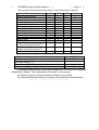
By means of an internal microprocessor it simultaneously measures:
Parameter
Voltage (phase-neutral)
Voltage (phase-phase)
Current
Neutral current
Active power
Reactive power L
Reactive power C
Power factor
Apparent power
Frequency
Power demand
Voltage THD
Current THD
Individual harmonic
current content (Up to the 15th)
Individual harmonic
voltage content (Up to the 15th)
Flicker
Available:
L1
L2
L3
III
x
x
x
x
x
x
x
x
x
x
x
x
x
x
x
x
x
x
x
x
x
x
x
x
x
x
x
x
x
x
x
x
xx
x
x
xx
x
x
xx
xx
xx
xx
x
x
x
x
x: Display and communications
x
xx: Communications
Parameter
Date/Time dd/mm/yy hh:mm:ss
Active energy ( two indep. meters: demanded energy (+) and
generated energy (--) )
Reactive energy (inductive), two indep. meters
Reactive energy (capacitive), two indep. meters
CVM-BDM
TIME
kWh (+) and (--)
kvarh.L (+) and (--)
kvarh.C (+) and (--)
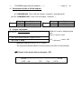
CVM-BDM permits above enumerated parameters to be view in a three-line
alphanumeric display. Three parameters are shown in every screen.
(a) Phase-to-neutral or phase-to-phase voltage of every phase.
(b) User-selectable parameters according to the model (see attached table).
---------------------------------------------------------------------------------------------
-----
CVM-BDM supply network analyzer --------
--- Page Nº
6
And also the MAXIMUM POWER DEMAND: The power demand is
integrated during a prefixed period.
You can select:
a) The parameter to be controlled (it can measure active power kW,
apparent power kVA or three phase average current AIII).
b) The demand period (1 to 60 min.).
This power demand function works with sliding window: shows the
accumulated demand over the last period from "now".
--------------------------------------------------------------------------------------------CVM-BDM is equipped with an internal memory for the collection of main
parameters from the electric network.
By means of the PC see, the user can select the parameters to be save into
memory among all measured by the power meter (instantaneous, maximum and
minimum values). You can also set the data recording period.
2.1.- Other features
-
DIN rail mounting device with low dimensions.
True RMS value measurements.
Internal memory (1Mbyte)
Measurements in all four quadrants.
Power demand
Memorizes Maximum and Minimum values.
2 leds for the indication of CPU and communications performance.
Harmonic distortion measurement (THD-V & THD-A ).
Individual harmonic current content (Up to the 15th)
Flicker measurement (PST & WA)
Neutral current calculation.
-----
CVM-BDM supply network analyzer --------
--- Page Nº
7
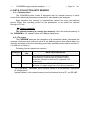
2.2.- Types of CVM-BDM
Available standard CVM-BDM types are:
CVM-BDM
7 70 290
7 70 291
7 70 292
7 70 293
Type
CVM-BDM
CVM-BDM-C2
CVM-BDM-C420
CVM-BDM-420
Description
Communications, internal memory and data display
CVM-BDM +2 relay outputs
CVM-BDM +1 relay output + 1 analog output
CVM-BDM + 2 analog outputs
Different CVM-BDM... provide more parameters to be displayed (additional SETUP).
3.- INSTALLATION AND STARTUP
The manual you hold in your hands contains information and
warnings that the user should respect in order to guarantee a proper
operation of all the instrument functions and keep its safety conditions.
The instrument must not be powered and used until its definitive
assembly on the cabinet’s door.
Whether the instrument is not used as manufacturer’s specifications, the
protection of the instrument can be damaged.
When any protection failure is suspected to exist (for example, it presents
external visible damages), the instrument must be immediately powered off. In this
case contact a qualified service representative.
-----
CVM-BDM supply network analyzer --------
--- Page Nº
8
3.1.- Installation
Before applying AC power to the, check following points :
a.- Supply voltage :
- Power supply Va.c. ( Single phase ) 50 ...60 Hz
230 V a.c.
- Frequency
: 50 ... 60 Hz
- Supply tolerance
: + 10 % / --15 %
- Connection terminals
: Terminals
- Instrument burden
: 6 VA
1 - 28
b.- Maximum voltage at the voltage measuring circuit:
Standard: 500 V a.c. phase-neutral / 866 V c.a. between phases
A special model CVM-BDM for 110 V measurement is also available:
100 V a.c. phase-neutral / 173 V a.c. between phases
c.- Maximum admissible current : Transformer of In / 5 A a.c.
d.- Operation conditions :
- Operating temperature : 0 to 50ºC
- Humidity : 25 to 80 % R.H. not-condensing
e.- Safety : Designed to meet protection class II as per EN 61010.
-----
CVM-BDM supply network analyzer --------
--- Page Nº
9
Installation :
The instrument is to be fit onto a DIN 46277 (EN 50022) rail . All connections
keep inside the cabinet.
Note that with the instrument powered on, the terminals could be dangerous to
touching and cover opening actions or elements removal may allow accessing
dangerous parts. Therefore, the instrument must not be used until this is completely
installed.
The instrument must be connected to a power supply circuit protected with gl
type (IEC 269 ) or M type fuses rated between 0.5 and 2 A. This circuit should be
provided with a circuit breaker or any equivalent element to connect or disconnect the
instrument from the power supply network. The supply and measuring voltage circuits
will be both connected through a wire with a minimum cross-section of 1 mm2.
The line of the current transformer secondary will have a minimum cross2
section of 2,5 mm .
-----
CVM-BDM supply network analyzer --------
--- Page Nº
3.2.- CVM-BDM Connection terminal (see side labels)
Terminal No
Designation
1 - 28
A1 - A2
27 - 26
dep. model
25 - 24
dep. model
Termination
23 - 19
resistor (RT)
22
21
20
16
17
18
15
14
13
12
11 - 10
9- 8
7- 6
+
GND
--
N
VL3
VL2
VL1
I L3: s1 - s2
I L2: s1 - s2
I L1: s1 - s2
Concept
supply voltage : 230 V a.c.
Relay output No. 1 / 1 output of 4- 20 mA
Relay output No. 2 / 2 output of 4- 20 mA
240 Ω resistor: adaptation of the line final
impedance ( bridge 23 -- 22 and 19 -- 20 )
COM1 CVM-B : RS-485 connection to the PC
22 +
--------------> 1 (+)
21 GND --------------> 5
converter
20 ----------------> 2 (--) RS-485/RS-232
No used.
No used.
No used.
NEUTRAL
Voltage phase 3
Voltage phase 2
Voltage phase 1
Current phase L3
.../ 5 A
Current phase L2
.../ 5 A
Current phase L1
... / 5 A
NOTE: Current inputs are isolated in the CVM-BDM model
10
-----
CVM-BDM supply network analyzer --------
--- Page Nº
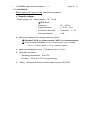
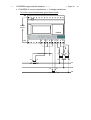
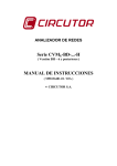
3.3.- Connection drawing for the CVM-BDM:
a.- CVM-BDM: Three-phase network.- 4 wires (low voltage) :
A2
N
28
CVM-BDM
A1
1
S2
P2
S1
P1 S2
P2
L1
S1
P1 S2
P2
S1
P1
L2
L3
N
11
-----
CVM-BDM supply network analyzer --------
--- Page Nº
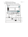
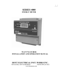
b.- CVM-BDM: 3 current transformers + 2 voltage transformer :
A2
POWER
SUPPLY
CVM-BDM
A1
1
6
S2
P2
7
8
9
S1
P1
10 11 12
13 14
S2
S1
S2
S1
P2
P1
P2
P1
L1
S2
P2
S1
P1
L2
S2
P2
S1
P1
L3
12
-----
CVM-BDM supply network analyzer --------
--- Page Nº
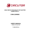
c.- CVM-BDM: 2 current transformers + 2 voltage transformer.
S2 of the current transformer grounded to earth
A2
POWER
SUPPLY
CVM-BDM
A1
1
6
S2
P2
7
8
9
S1
10 11 12
13 14
S2
S1
S2
S1
P2
P1
P2
P1
L1
P1
L2
S2
P2
S1
P1
L3
13
-----
CVM-BDM supply network analyzer --------
--- Page Nº
S1 of the current transformer grounded to earth
A2
POWER
SUPPLY
CVM-BDM
A1
1
6
7
8
9
10 11 12
S2
S2
P2
S1
P2
13 14
S1
P1
S2
S1
P2
P1
L1
P1
L2
S2
P2
S1
P1
L3
14
-----
CVM-BDM supply network analyzer --------
--- Page Nº
15
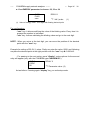
4.- OPERATION MODE
The instrument has a display with three lines (10 characters every line).
When you switch on the power supply of the CVM-BDM you will see on the display:
Card
xxxxx
xxxx
Circ
utor
yyy
Where:
xxxx = hardware configuration.
yyy = Versión software
After some seconds the instrument is ready to work, showing one of the
possible screens. The display indicates the parameter presently shown.
display
The first display shows the voltage of phase L1 (V1), the voltage of phase L2
(V2) and the voltage of phase L3 (V3).
220
V1
220
V2
220
V3
If you press the "display" key, we are now reading the CURRENT values for
each phase (A1, A2, A3). However, this screen can be configured in order to display
other different parameters.
When pressing again the "display" key, we will see on display the three
previously programmed parameters. If you press the "display" key again you can
see from 1 to 15 screens depending of the previous setup.
-----
CVM-BDM supply network analyzer --------
--- Page Nº
16
max
Pressing the "max" key, the maximum values for the parameters being shown
appear in the displays.
xxxx
MAX
xxxx
MAX
xxxx
MAX
This function is only valid while you keep pressing the "max" key. If you stop
pressing the key the instantaneous values appear again.
min
Pressing the "min" key, the minimum values
appear in the displays.
xxxx
xxxx
xxxx
for the parameters being shown
MIN
MIN
MIN
This function is only valid while you keep pressing the "min" key. If you stop
pressing the key the instantaneous values appear again.
Reset
Pressing the "reset" key the system is reset. This is equivalent to switch off
the power supply of the instrument. The stored maximum and minimum values will be
automatically deleted from the internal memory.
If you are in the setup process and press the "reset" key, you exit it without
saving any modification that you have done and making a reset of the system.
CVM-BDM supply network analyzer --------
-----
--- Page Nº
17
5.- SETUP PROCEDURE
The setup procedure of the CVM-BDM is performed by means of several
SETUP options.
For accessing the setup menu the keys max & min must be
simultaneously pressed once the instrument is at the main screen.
When accessing the SETUP, the message "SETUP unloc " (1) is shown for
some seconds on screen, or, otherwise, the message "SETUP loc" (2).
(1) Setup UNLOC (SETUP unlocked ) : when the SETUP is accessed,
configuration parameters can be either visualized and modified.
(2) Setup LOC (SETUP locked ) : when the SETUP is accessed,
configuration parameters can be visualized but cannot be modified .
Once into the SETUP, use the keyboard to select different options and enter
required variables:
-
The key Display validates de value and pass to the next menu.
-
The key MAX permits to select among different options in a menu, or to
increase a digit when a variable is being entered.
-
The key MIN permits to move the cursor along the digits.
Different options are following shown in a sequential mode:
-----
CVM-BDM supply network analyzer --------
--- Page Nº
18
5.1.- Phase-to-Phase or Phase-to-Neutral voltages
After the word "set" you will see on the three displays the voltages of the
phases L1, L2, L3.
U1
U2
U3
or
U12
U23
U31
Phase to Neutral Voltages:
U1 , U2 , U3
Phase to Phase Voltages :
U12 , U23 , U31
a) To select one of the voltage options just press the green key "max"
and both options will appear alternately.
b)
b.- When you get in the display the wished option just press the
"display" key to validate it and access to the next setup option.
-----
CVM-BDM supply network analyzer --------
--- Page Nº
19
5.2.- Voltage transformation ratio.
5.2.1.- Voltage Transformer Primary.
On the screen we read the word "SET U P" followed by 6 digits. They allow us
setting the primary of the voltage transformer.
SET U
P-----
Last digit of the first display indicates "U" (Voltage) and first digit of the second
display indicates "P" (Primary). It means that we can set the primary of the voltage
transformer. To avoid mistakes the Voltage red leds remain lit on.
a) To write or modify the value just repeatedly press the "max" key and the
blinking digit value will be increased.
b) When the value on screen is the proper one, we can pass to the next digit by
pressing the "min" key in order to modify the other values.
c) When the blinking digit is the last one, pressing the "min" key we go back to
the initial value: set values can be again modified.
d) Press "display" to pass to the next setup option.
Note: Maximum values of transformation ratios which are allowable to be set,
depend on the full-scale value of the measuring instrument. (see side labels).
FULL-SCALE
VALUE
110 V~
300 V~
500 V~
MAXIMUM ALLOWABLE
VALUE
99,999
70,000
40,000
-----
CVM-BDM supply network analyzer --------
--- Page Nº
20
5.2.2.- Voltage Transformer Secondary
We can now set the value of the secondary of the voltage transformer. Only
three digits are available:
SET U
S
---
The procedure is the same one done at the previous sections with the "max",
"min" and "display" keys.
If the CVM-BDM is directly connected to the mains (without voltage
transformer) the values of primary and secondary must be the same, for instance
000001/001.
5.3.- Current Transformer Primary
"SET A P" and five digits appear on screen allowing us to set the primary of
the current transformer. The current green leds light on to avoid mistakes.
SET A
P ----
The procedure is the same one done at the previous sections with the "max",
"min" and "display" keys.
NOTES:
- The secondary of the current transformers is not programmable. It is
automatically set at 5 A (... / 5 A ac)
-
The primary current value to be set is also limited by the following condition:
The maximum allowable primary current value which can be set is defined
by the fact that the multiplication of the primary voltage value by this
primary current value cannot exceed 20,000,000.
-----
CVM-BDM supply network analyzer --------
--- Page Nº
21
5.4.- Network specifications
5.4.1.- Rated voltage
The message "SET n" is on screen, together with three digits to set the rated
voltage of the monitored power system. Whether the voltage measurement is carried
out through the secondary of voltage transformers, then the rated voltage of the
transformer secondary must be set. (Phase-to-neutral voltage).
SET
n
- - Proceed as for previous sections when using "max", "min" & "display" keys.
Examples :
-
Direct measurement: Transforming ratio 1/1 Set n = 230
-
Through transformers: 22000/110 Set n = 110
5.4.2.- Rated frequency
The screens shows "SET freq” and two digits to set the rated frequency of the
monitored power system.
SET
Freq
- - Proceed similarly than for previous sections by means of the "max", "min" and
"display" keys.
-----
CVM-BDM supply network analyzer --------
--- Page Nº
22
5.5.- Integration period of voltage and frequency signals
The screens shows ""SET int”” and two digits to set the desired integration
period of voltage and frequency signals.
SET
int
- -
Allowable value:
from 1 to 60 s
Proceed similarly than for previous sections by means of the "max", "min" and
"display" keys.
For the calculation of the average, maximum and minimum voltage and
frequency values, the CVM-BDM obtains one value every second. These values
equal the average of the values calculated within the time window set by the user
(time constant). If the time value is 1 second, then the viewed value equals the
instantaneous value.
-----
CVM-BDM supply network analyzer --------
--- Page Nº
23
5.6.- Parameter SETUP
This option allows to program until 45 optional parameters that you can see on
15 programmable pages (3 parameters every page).
The CVM-BDM asks first if you want to program the default parameters.
"max" key : you can select YES or NO. The “display” key allows the validation
of the selected option.
dEF
PAGE
YES
a) Select “YES” to program the default parameters. It pass to the next option.
b) If you select “NO”, it allows programming the parameters that you want to see
on the display. Every new page, it asks if you want to continue this setup .
SET
PAGE NUMBER
YES
xx
<--- page No.
- If you select “SET PAGE YES”, you
page:
xx
xx
xx
Parameter code ( setup )
can program the desired parameters in this
A1
A2
A3
/ Parameter symbol
Setup:
− "max" key: Allows us modifying the value of the blinking digit. Each time it
is pressed the value is increased.
− "min" key : Allows us the validation of the blinking digit and going to the
next one.
Each display has two digits to select the desired parameters among the ones
in the attached code chart.
-----
CVM-BDM supply network analyzer --------
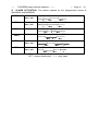
Parameter
Single voltage
Current
Active power
Inductive power
Capacitive power
Power factor
Symbol
phase L1
Code
V1
A1
kW 1
kvarL 1
kvarC 1
PF 1
Three phase single voltage
Three phase current
Three phase active power
Three. ph. inductive power.
Three ph. capacitive power
Three ph. power factor.
01
02
03
04
05
06
Vav III
Aav III
kW III
kvarL III
kvarC III
PF III
Date/ TIME dd/mm/yy hh:mm:ss
Active energy
Reactive energy (inductive)
Reactive energy (capacitive)
Demand power ( kW, kVA, AIII)
Active energy generated
Reactive energy (inductive) gen.
Reactive energy (capacitive) gen.
Neutral current
Parameter
Voltage THD
Current THD
Flicker
Symbol
phase L1
% THD V1
% THD I1
WA_V1
PST_V1
Symbol
phase L2
--- Page Nº
Code
V2
A2
kW 2
kvarL 2
kvarC 2
PF 2
19
20
21
22
23
24
Symbol
phase L3
07
08
09
10
11
12
TIME
kW.h
kvarh.L
kvarh.C
Pd
kW.h -kvarh.L -kvarh.C -IN
Code
54
57
60
63
Symbol
phase L2
% THD V2
% THD I2
WA_V2
PST_V2
Code
V3
A3
kW 3
kvarL 3
kvarC 3
PF 3
Frequency
Three ph. apparent power
Ph-Ph voltage L1- L2
Ph-Ph voltage L2 - L3
Ph-Ph voltage L3 - L1
Three ph. Ph-Ph voltage
24
13
14
15
16
17
18
Hz
kVA III
V 12
V 23
V 31
Vc III
25
26
27
28
29
30
31
32
33
34
35
36
37
38
53
Code
55
58
61
64
Symbol
phase L3
% THD V3
% THD I3
WA_V3
PST_V3
- For passing to the next page , press "display". In this case the CVM-BDM
ask again:
Code
56
59
62
65
-----
CVM-BDM supply network analyzer --------
--- Page Nº
25
SET
PAGE NUMBER
YES
xx
- If you select “SET PAGE YES” , you can setup a next page.
- If you don’t want to setup more pages, select “SET PAGE No”, and it pass
to the next setup option (5.7.-First Page SETUP ). You can see the first page of
voltages and all the programmed pages .
5.7.- First Page SETUP
This option allows selecting among fixed or rotary page:
a.- Fixed page: the page is changed pressing the "display" key. The page
among the available ones that we want to see when the CVM-BDM is supplied (or a
reset is made) can be selected.
b.- Rotary pages: the page changes to the next one automatically every 5
seconds. ( “SET AUTO PAGE : Rotate page select “ option ).
Setup :
- The "max" key allows modifying the selected page. The display shows the
different possible pages.
SET
xx
AUTO
xx
PAGE
xx
<-- setup parameters
- The "display" key allows the validation of the chosen option.
-----
CVM-BDM supply network analyzer --------
--- Page Nº
26
5.8.- Maximum power demand
Push the key "display" and the following screens will appear by display:
1) PARAMETER TO CONTROL
None
Three phase active power
Three phase apparent power
Three phase average current
("SET Pd xx")
00
kW III
21
kVA III
26
AavIII
20
Value of power integrated during the programmed demand period.
2) DEMAND PERIOD ( 1 to 60 min.)
3)
("SET Per xx")
CLEAR MAXIMUM VALUE IN MEMORY
("CLr Pd xx")
no or YES
PROGRAMMING MODE:
- "max" key: allows choosing the different available options.
- "min" key: allows the validation of the blinking digit and go forward to
the next digit (only for the "SET Per xx" option).
- To pass to the next option press "display".
If you don't want to modify anything, just press the "display" key three times
without modifying any value.
- Display: If you program the MAXIMUM POWER DEMAND option,
parameter 35, the following appears by display (depending on the pressed key):
display
max
min
Present value of the demand power meter (Sliding Window,
according to the set demand period) updated every second.
MAXIMUM integrated value (since last reset)
HOUR : MINUTE DAY : MONTH (“”HH.MM DD/MM”)
when this maximum has occurred
OTHER SETUP SCREENS : THE ENERGY AND CLOCK MODULES
-----
CVM-BDM supply network analyzer --------
--- Page Nº
27
5.9.- DATE / TIME SETUP
Pressing the "display" key we will see in the CVM-BDM screen the following:
1.- DAY : MONTH
("SET day dd:mm")
2.- YEAR
("SET YEAR xxxx " )
4 digits
3.- HOURS : MINUTES ("SET HOUR hh:mm")
For their setup:
- "max" key: Allows modifying the value of the blinking digit.
- "min" key: Allows the validation of the blinking digits and go to the next one.
- To pass to the next option press "display".
If you don't want to modify the time, just press three times "display" without
making any modification.
- Display: If you select the parameter 31, following appears by display:
display
max
min
HOUR .MINUTES
DAY. MONTH
MINUTES . SEC.
-----
CVM-BDM supply network analyzer --------
--- Page Nº
28
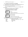
5.10.- Clearing energy counters
On display we see "CLR ENER no" (Clear energy counters).
- "max"
: To select "YES" or "no"
- "display" : To validate the selected option. Once finishing this option, all
the modifications that we have done are saved into memory and the setup process is
finished.
- Display
: If any of the energies is programmed (kWh, kvarhL or kvarhC),
it is displayed as follows:
[display]
[max]
[min]
XXXX kW.h
XXX XXX. XXX
XXXX (1 )
4 meter digits (more significant ) / units
complete meter
4 digits / Tariff type ( 1, 2 or 3 )
Example: If the accumulated energy is 32.534,810 kWh, it will be displayed as
follows:
[display]
[max]
[min]
2534 kW.h
32534. 810
2534 ( 1 )
-----
CVM-BDM supply network analyzer --------
--- Page Nº
29
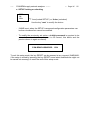
5.11.- Memory SETUP
Once the setup for the analyzer performance is completed, the memory is then
configured.
Firstly set the recording period:
Set
Per data
001 min.
Recording period
Recording period must be set within 1 to 240 min.
-
Press the "max" key and the blinking digit value will be increased.
-
Press the "min" key to pass to the next digit in order to modify the other values.
-
Press "display" to access other options.
To ends the analyzer configuration, the user is inquired whether the internal
memory of the analyzer is desired to be deleted.
Clr
Data
no/yes
Memory clear
-
Use the "max" key to select the memory data to be deleted (yes) or kept (no).
-
Use the "display" key to validate the selected option. Once finishing this option,
all the modifications that we have done are saved into memory and the setup
process is finished.
-----
CVM-BDM supply network analyzer --------
--- Page Nº
30
5.12.- THD or D setting
SET
dHAR
d
or
SET
dHAR
Thd
Two modes for the harmonic distortion calculation can be selected:
-
d % : total value of the harmonic distortion referred to the fundamental value.
-
Thd % : total value of the harmonic distortion referred to the RMS value.
The selected option will be the one shown on screen.
a.- To select any option just press "max" to switch between the two available
options.
b.- Press " Display " to validate the choice. Since all setup options have been
completed, the setup is exited, all modifications are saved into memory, and the
running mode automatically starts up.
-----
CVM-BDM supply network analyzer --------
--- Page Nº
31
5.13.- Additional screen with the relay output.
CVM-BDM-C2 (2 relays ) & CVM-BDM-C420 (1 relay )
With these outputs the CVM-BDM can be configured for:
A.- Pulse every certain kW.h or kvar.h (ENERGY). You can define the value
corresponding to the energy consumed for generating a pulse (0.5 sec. long): kW.h /
1 pulse or kvar.h / 1 pulse
B.- ALARM conditions: the parameter to be controlled, the maximum value,
the minimum value and the "delay" are programmed for each relay output.
---------------------------------------------------------------------------------On the CVM-BDM-C2 & CVM-BDM-C420 screen following messages appear
at this SETUP point:
OUT 1
CODE
00
RELAY 1
Parameter No.
(1)
Depending on the selected variable we will pass to a.- or b.- sections
In case that no parameter is wanted to be programmed set par. No. = 00.
-----
CVM-BDM supply network analyzer --------
--- Page Nº
32
a.- If an ENERGY parameter is chosen: 32, 33 or 34
OUT 1
PULS
xxxx
RELAY 1
kW / pulse
(1)
(1) Value of energy in kW : four digits with floating decimal point
For configuration:
- "max" key: it allows modifying the value of the blinking value. Every time it is
pressed the number is increased.
- "min" key: it allows validating the blinking value and go to the next digit.
NOTE : When you arrive at the last digit, you can move the position of the decimal
point with the "max" key.
Example for setting a 500 W / 1 pulse: Firstly we enter the value, 0500, and following
we place the decimal point at the right position with the "max" key
0.500 kW.
- For passing to the next option, press "display": setup options for the second
relay will appear (only with the CVM-BDM type CVM-BDM-C2 ).
OUT 2
CODE
00
RELAY 2
Parameter value
(2)
Act as before. Pressing again "display" key you exit setup mode.
-----
CVM-BDM supply network analyzer --------
--- Page Nº
33
b.- ALARM conditions (1 condition for each relay): If any other parameter (1
to 30, 35 or 54 to 59) is selected in (1), two outputs can be configured as alarms. For
each output it is possible to program:
Any of the parameters measured by the CVM-BDM
MAXIMUM value
MINIMUM value
Delay for the conditions
These screens are successively displayed by the CVM-BDM once the
parameter has been selected (for the setup of each option proceed as in the Section
a.-):
b.1.- Programming the maximum value to be controlled:
OUT 1
RELAY 1
AL hI
0.000
Maximum value
b.2.- Programming the minimum value to be controlled:
OUT 1
RELAY 1
AL LO
0.000
Minimum value
b.3.- Delay setup:
OUT 1
SEC
0.000
RELAY 1
Delay in seconds
maximum 9999 sec.
- Press "display" to pass to the next option: the setup for the second relay appears
(only with CVM-BDM type CVM-BDM-C2 ).
OUT 2
RELAY 2
CODE
00
Parameter No. (1)
Proceed as before. Pressing again "display" we exit the setup option.
-----
CVM-BDM supply network analyzer --------
--- Page Nº
34
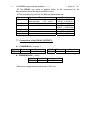
ALARM ACTIVATION: The alarms depend on the programmed values of
MAXIMUM and MINIMUM.
MIN +
MAX +
max > min
MIN +
MAX +
max < min
MIN --
MAX +
MIN +
MAX --
MIN --
MAX -max > min
MIN --
MAX -max < min
ON
OFF
ON
╠=======╣
0
Min
Max
OFF
ON
OFF
========╣╠======
0
Max
Min
ON
OFF
ON
╠======╣
Min
0
Max
OFF
ON
OFF
=======╣╠=======
Max 0
Min
ON
OFF
ON
╠======╣
Min
Max
0
OFF
ON
OFF
=====╣╠===========
Max
Min
0
ON = alarm activated ----------> relay closed
OFF = alarm deactivated ------> relay open
-----
CVM-BDM supply network analyzer --------
--- Page Nº
35
The DELAY set value is applied either to the connection or the
disconnection when the alarm conditions occur.
The programming units for the different parameters are:
Parameter
Voltage
Current
Powers
Format
Without decimals = V
(xxxx)
With decimals
= kV (xxx.x)
A
kW, kvar, kVA
Energies
Power factor
Frequency
kW.h, kvar.h
x.xx
xx.x
Example
0220 = 220 V
25.30 = 25.30 kV
0150 = 150 A
0.540 = 540 W
250.5 = 250.5 kW
- 0.7 = - 0.70
50.0 = 50 Hz
Connections of the RELAY OUTPUTS :
a.- CVM-BDM-C2 ( 2 relays ) :
Out1
Terminals
27 - 26
RELAY1
Signal
N.O.
Out2
Terminals
25- 24
RELAY2
b.- CVM-BDM-C420 ( 1relay ) :
Out2
Terminals
25 - 24
RELAY1
Signal
N.O.
- Maximum voltage between terminals = 250 V a.c.
Signal
N.O.
-----
CVM-BDM supply network analyzer --------
--- Page Nº
36
5.14.- Additional screen with the 4 - 20 mA outputs.
4 - 20 mA outputs : CVM-BDM-420 (2 analog outputs) and
CVM-BDM-C420 (1 relay +1 analog output).
With this outputs we can configure the CVM-BDM to give an output of 4 - 20
mA d.c. or of 0 - 20 mA d.c. ( resolution of 4.000 points ) proportional to any of
the parameters measured by the CVM-BDM, with the ability of setting the scale
(offset and full scale).
On the CVM-BDM screen following messages appear at this SETUP point
(provided the right module is connected to the equipment):
a.- Parameter choosing:
dA 1
Code
Xx
OUTPUT D/A No.1
Parameter No.
-
"max" -- "min" keys: allow the selection of any parameter from 01 to 30
-
"display" key: validates the selected option and passes to the next setup
screen.
b.- Election of 0 - 20 mA or 4 - 20 mA :
dA 1
Scal
4 - 20
OUTPUT D/A No.1
Scale :
allows choosing a 0 - 20 mA
or 4 - 20 output ("max" or "min" key)
- "display": to validate the selected option and pass to the next setup screen.
CVM-BDM supply network analyzer --------
-----
--- Page Nº
37
c.- Scale offset:
Value of the parameter that we assign as the zero of the scale.
dA 1
Zero
x.xxx
OUTPUT D/A No.1
zero of the scale:
allows choosing the zero of the scale
(four digits with floating decimal point)
-
"max" key: it allows modifying the value of the blinking value. Every time it is
pressed the number is increased.
-
"min" key: it allows validating the blinking value and go to the next digit.
NOTE : When you arrive at the last digit, you can move the position of the decimal
point with the "max" key.
-
"display": to validate the selected option and pass to the next setup screen.
d.- Full scale: Value of the parameter to which we assign the 20 mA.
dA 1
F.ESC
x.xxx
OUTPUT D/A No.1
Full scale:
allows choosing the full scale (20 mA)
(four digits with floating decimal point)
Proceed as in the previous section.
- For passing to the next option, press "display": the setup for the second
output will appear (only with a CVM-BDM type CVM-BDM-420).
dA 2
code
xxxx
OUTPUT D/A No.2
Proceed as in the previous sections.
-----
CVM-BDM supply network analyzer --------
--- Page Nº
38
1.- Connections of the 4- 20 mA outputs :
a.- CVM-BDM-420 (Two 4-20 mA outputs : channel 1 and channel 2 )
and b.- CVM-BDM-C420 ( One 4-20 mA output : channel 1 )
Terminals
27
Channel
26
1
Signal
20 mA (--) (Common)
20 mA (+)
Terminals
25
Channel
24
2
2.- Output calculation:
( 20 − Zero )
Re solution =
( F .scale − Offset )
Signal
20 mA (--) (Common)
20 mA (+)
Offset & f. scale = defined by the
user
Zero = 0 mA or 4 mA
-
mA = Re solution * (Mesure − Offset ) + Zero
-
mV = mA x ohms
mV (100 ohms) = mA x 100
-
Maximum load is of 250 Ω (5 V - 20 mA)
-
The maximum allowed offset is a value equal to the 90% of the full scale.
Output of the power factor parameter ( PF):
0/4 mA ---------------------------- -------------------------20 mA
+0.00
Ind.
1.00
Cap.
0.00
-----
CVM-BDM supply network analyzer --------
--- Page Nº
39
6.- DATA COLLECTION INTO MEMORY
6.1.- Characteristics
The CVM-BDM power meter is equipped with an internal memory to store
some all the electrical parameters measured or calculated by the analyzer.
Data collection into memory is automatically carried out every user-defined
period. Either this recording period as the parameters to be saved are defined
through a PC set.
Point to consider
The internal memory is a rotary type memory: Once the internal memory of
the CVM-BDM is full, newest values will replace oldest ones.
6.2.- File types
The CVM-BDM executes the integration of all measured values, calculates the
average, maximum and minimum value of the defined period, and collects data into
memory according to the set recording period (the available period can be set from 1
s to 240 min (4 hours )).
Following files are saved into memory:
xx.STD
Register
size
variable
xx.EVE
6 bytes
Extension
DATA saved into the file
Only saves into memory the selected parameters:
instantaneous, maximum and or minimum values.
Parameter selection is done via PC (maximum 130
parameters).
Power ON - Power OFF (DATE - TIME):
date/time of voltage supply loss, and restoring date/time
-
The CVM-BDM... calculates every second values of all parameters, regardless
its configuration.
-
Internal values in the internal memory can be retrieved from a PC, via RS-485.
-----
CVM-BDM supply network analyzer --------
--- Page Nº
40
6.3.- Memory capacity
The quantity of records that can be saved into the internal memory will depend
on the number of parameters selected to be stored. Memory capacity is indicated in
the following table:
*.STD
Maximum size
1 Mbyte
Register size
6 + (4 * no. parameters )
No. of registers
1000000
6 + (4 * no. parameters)
*.EVE
1 kbyte
6 bytes
170 events
xx.STD TYPE FILE:
This type of file permits the user to select the parameters to be saved into
memory. The maximum number of parameters that the CVM-BDM can collect into
memory is 130 variables (the energies count like two parameters).
The size of each register will depend on the number of parameters selected by
the user to be stored. The number of registers that can be saved into the memory
can be calculated just applying the following formula:
1000000
No. of registers =
6 + (4 * No. Parameters)
6.4.- Setting the memory up from PC.
The choice of parameters to be stored by the CVM-BDM must be carried out
through a PC by means of the Power-Vision software.
This software permits to read the SETUP saved into the own CVM-BDM, and
following operation parameters can be defined:
FIELD
DESCRIPTION
Recording period
Parameters to save into mremory
between 1 second to 4 hours
Choice of the parameters to be saved into memory.
When the choice of parameters to be saved into memory by the CVM-BDM is
modified in the SETUP options, the internal memory is completely deleted
-----
CVM-BDM supply network analyzer --------
--- Page Nº
41
7.- CONTRAST.
For a correct visualization of the display, you can set the display’s contrast by
pressing the buttons DISPLAY+Máx to increase, and DISPLAY + Min to decrease.
-----
CVM-BDM supply network analyzer --------
--- Page Nº
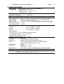
8.- SPECIFICATIONS
Power supply : see specifications on the own CVM-BDM rear
- CVM-BDM:
Single phase 230 V a.c.
Voltage tolerance: +10 % / -15 %
Frequency: 50 ... 60 Hz
Power consumption ..................... 6 VA
Operation temperature ................ 0 to 50º C
Internal memory : 1Mbyte Memory
Measuring Circuits :
Rated voltage ........... 500 V a.c. Phase - Neutral / 866 V a.c. between phases
Other voltages ............Through Voltage Transformers
Rated current ..............In / 5 A ; In / 1 A by model. (isolated input like ITF models)
Permanent overload .....1.2 In
Current input power .....0.6 VA
Accuracy :
Voltage ...................................... 0.5 % of readout ± 2 digits
Current ...................................... 0.5 % of readout ± 2 digits
Powers ...................................... 1 % of readout ± 2 digits
Test conditions :
- Errors due to C.T.’s not included and direct voltage
- Temperature between + 5 ºC and + 45 ºC
- Power factor between 0.5 and 1
- Measured values between 5 % ... 100 %
Constructive characteristics :
Box type :
Self-extinguishing, plastic casing
Connection :
Metallic terminals with "posidraft" screws
Fixing :
Fitted onto symmetrical DIN 46277 (EN 50022) rail
Screw fixing (Passing hole ∅ 4,2 mm).
Frontal cover :
Lexan
Protection :
Built-in relay : IP 41
Terminals
: IP 20
Dimensions
140 x 70 x 110 mm ( 8 modules relay as per DIN 43 880)
Safety................................... Category II as per EN-61010
Standards : EN 60664, EN 61010-1, EN 61036, IEC 60801 ,IEC 60571-1,
EN 50081-1, EN 50082-1, VDE 110 , UL 94
42
-----
CVM-BDM supply network analyzer --------
--- Page Nº
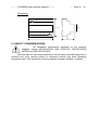
43
Dimensions :
45
110
140
70
9.- SAFETY CONSIDERATIONS
All installation specification described at the previous
chapters named INSTALLATION AND STARTUP, INSTALLATION
MODES and SPECIFICATIONS.
Note that with the instrument powered on, the terminals could be dangerous to
touching and cover opening actions or elements removal may allow accessing
dangerous parts. This instrument is factory-shipped at proper operation condition.
-----
CVM-BDM supply network analyzer --------
--- Page Nº
44
10.- MAINTENANCE
The CVM-BDM does not require any special maintenance. No adjustment,
maintenance or repairing action should be done over the instrument open and
powered and, should those actions are essential, high-qualified operators must
perform them.
Before any adjustment, replacement, maintenance or repairing operation is
carried out, the instrument must be disconnected from any power supply source.
When any protection failure is suspected to exist, the instrument must be
immediately put out of service. The instrument’s design allow a quick replacement in
case of any failure.
11.- TECHNICAL ASSISTANCE SERVICE (T.A.S.)
For any inquiry about the instrument performance or whether any failure
happens, contact to CIRCUTOR’s technical service.
CIRCUTOR S.A.
Vial Sant Jordi, s/n
08232 – Viladecavalls
Barcelona – SPAIN
Tel: (+34) 93 745 29 00
Fax :(+34)-93 745 29 14
e-mail: [email protected]
www.circutor.es
-----
CVM-BDM supply network analyzer --------
--- Page Nº
45
12.- CVM-BDM... COMMUNICATIONS
---One or some CVM-BDM... can be connected to a P.C.. With this system we
can get all the parameters in one central point of reading. The CVM-BDM..., has a
serial RS-485 type output. If we connect more than one device to the same
communication line, we have to assign to each of them a different code or direction
(from 01 to 255), since the P.C. needs the identification of every measuring point
12.1.- ! To take into account:
- PROTOCOL: MODBUS ©
(Question / Answer)
- CVM-BDM DEFAULT CONFIGURATION : 001 / 9.600 / 8 bits / N / 1 bit
- Available baud rates: 1.200 - 2.400 - 4.800 - 9.600 - 19.200 bauds
- RS-485 type output:
− RS-485 connection will be carried out by means of a twisted and
screened cable, with a minimum of 3 wires, with a maximum
distance between the CVM-BDM and the last peripheral of 1.200 m.
The CVM-BDM uses a RS-485 communication bus allowing up to a
maximum of 32 devices in parallel (Multi-point bus) per port
used in the PC.
-----
CVM-BDM supply network analyzer --------
--- Page Nº
46
12.2.- RS-485 type connection to a RS-232 type input of a PC
RS-232
5
DB-9
A2
5
7
7
3
2
3
2
PC
A1
CONVERTIDOR
RS-232 / RS-485
5
2
1
5
RS-485
2
1
21
22
20
CVM-BDM
*If the RS485/232 converter with RTS control ability (code 770208) is used, then
the pin 7 connection in the 232 side is not necessary to be done.
-----
CVM-BDM supply network analyzer --------
--- Page Nº
47
12.3.- MODBUS © protocol
The CVM-BDM analyzer can communicate by means of the MODBUS
© protocol, as it is following described:
When the CVM-BDM communicates with MODBUS protocol, it uses the RTU
mode (Remote Terminal Unit ). Each 8-bits byte in a message contains two 4-bits
hexadecimal characters.
The format for each byte in RTU mode is :
* Code
:
8-bits binary, hexadecimal 0-9, A-F
Two hexadecimal characters
contained in each 8-bits field of the
message.
* Bits per Byte
:
8 data bits
* Error Check Field
:
Cyclical Redundancy Check ( CRC ) .
MODBUS FUNCTIONS:
FUNCTION 01
Reading of relay state
FUNCTION 3 or 4
Reading of n Words (16 bits-2 bytes). This function
permits to read all the electrical parameters of the
CVM-BDM. Each parameters is a 32-bits long,
hence two words are required to inquiry for a
parameter.
FUNCTION 05
Writing one relay
-----
CVM-BDM supply network analyzer --------
--- Page Nº
48
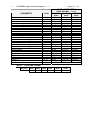
a.- Registers assigned to different parameters measured by the CVM-BDM:
MODBUS REGISTERS
Phase voltage - V 1
Current - A 1
Active power - kW1
inductive power-kvar L 1
Capacitive power – kvarC 1
Power factor - PF1
Phase voltage - V 2
Current - A 2
Active power - kW2
Inductive power-kvarL 2
Capacitive power – kvarC 2
Power factor - PF2
Phase voltage - V 3
Current - A 3
Active power - kW3
Inductive power– kvarL 3
Capacitive power – kvarC 3
Power factor - PF3
V x 10
mA
W
var L
var C
PF x 100
V x 10
mA
W
var L
var C
PF x 100
V x 10
mA
W
var L
var C
PF x 100
HEXA-DECIMAL (longs)
PRESENT MAXIMUM MINIMUM
Value
Value
Value
00-01
100-101
200-201
02-03
102-103
202-203
04-05
104-105
204-205
06-07
106-107
206-207
08-09
108-109
208-209
0A-0B
10A-10B
20A-20B
0C-0D
10C-10D
20C-20D
0E-0F
10E-10F
20E-20F
10-11
110-111
210-211
12-13
112-113
212-213
14-15
114-115
214-215
16-17
116-117
216-217
18-19
118-119
218-219
1A-1B
11A-11B
21A-21B
1C-1D
11C-11D
21C-21D
1E-1F
11E-11F
21E-21F
20-21
120-121
220-221
22-23
122-123
222-223
Phase voltage - V III
Current - A III
Three-phase active power - kW III
Three-phase inductive power– kvarL III
Three-phase capacitive power – kvarC III
Three-phase power factor - PF III
V x 10
mA
W
var
var
PF x 100
24-25
26-27
28-29
2A-2B
2C-2D
2E-2F
PARAMETER
Units
124-125
126-127
128-129
12A-12B
12C-12D
12E-12F
224-225
226-227
228-229
22A-22B
22C-22D
22E-22F
-----
CVM-BDM supply network analyzer --------
--- Page Nº
49
MODBUS REGISTERS
PARAMETER
Units
Frequency (L1) - Hz
Three-phase apparent power kVA III
Line-to-line voltage L1-L2 - V12
Line-to-line voltage L2-L3 - V23
Line-to-line voltage L3-L1 - V31
Line-to-line voltage III
Hz x 10
VA
V x 10
V x 10
V x 10
V x 10
Hours / minutes
Month / day
Minutes / seconds
HEXA-DECIMAL (longs)
PRESENT MAXIMUM MINIMUM
Value
Value
Value
30-31
130-131
230-231
32-33
132-133
232-233
34-35
134-135
234-235
36-37
136-137
236-237
38-39
138-139
238-239
3A-3B
13A-13B
23A-23B
3C-3D
13C-13D
23C-23D
Active energy (+) kW.h
Inductive reactive energy (+) kvar.h L
Capacitive reactive energy (+) kvar.h C
Maximum power demand
Active energy (-) kW.h
Inductive reactive energy (-) kvar.h L
Capacitive reactive energy (-) kvar.h C
W. h
var.h L
var.h C
Md (Pd)
W. h
var.h L
var.h C
3E-3F
40-41
42-43
44-45
46-47
48-49
4A-4B
144-145
244-245
Neutral current
IN
68-69
168-169
268-269
%THD V 1
%THD V 2
%THD V 3
%THD I 1
%THD I 2
%THD I 3
Date/Time *
% x 10
% x 10
% x 10
% x 10
% x 10
% x 10
6A-6B
16A-16B
26A-26B
6C-6D
16C-16D
26C-26D
6E-6F
16E-16F
26E-26F
70-71
170-171
270-271
72-73
172-173
272-273
74-75
174-175
274-275
2A94-2A95-2A96-2A97-2A98-2A99
* NOTE : DATE/TIME FORMAT
Register
2A94
2A95
2A96
2A97
2A98
2A99
Day
Month
Year
Hours
Minutes
Seconds
-----
CVM-BDM supply network analyzer --------
--- Page Nº
50
MODBUS REGISTERS
PARAMETER
Flicker WA - L1
Flicker WA - L2
Flicker WA - L3
Flicker PST - L1
Flicker PST - L2
Flicker PST - L3
PARAMETER
Units
Fundamental
A
V x10
% x10
% x10
% x10
% x10
% x10
% x10
% x10
% x10
% x10
% x10
% x10
% x10
% x10
% x10
Harmonic 2
Harmonic 3
Harmonic 4
Harmonic 5
Harmonic 6
Harmonic 7
Harmonic 8
Harmonic 9
Harmonic 10
Harmonic 11
Harmonic 12
Harmonic 13
Harmonic 14
Harmonic 15
Units
%x10
%x10
%x10
%x10
%x10
%x10
L1
320-321
322-323
324-325
326-327
328-329
32A-32B
32C-32D
32E-32F
330-331
332-333
334-335
336-337
338-339
33A-33B
33C-33D
HEXA-DECIMAL (longs)
PRESENT MAXIMUM MINIMUM
Value
Value
Value
76-77
176-177
276-277
78-79
178-179
278-279
7A-7B
17A-17B
27A-27B
7C-7D
17C-17D
27C-27D
7E-7F
17E-17F
27E-27F
80-81
180-181
280-281
MODBUS REGISTERS
HEXA-DECIMAL (longs)
Current
Voltage
L2
L3
L1
L2
33E-33F 35C-35D
37A-37B 398-399
340-341 35E-35F 37C-37D 39A-39B
342-343
360-361 37E-37F 39C-39D
344-345
362-363 380-381 39E-39F
346-347
364-365 382-383 3A0-3A1
348-349
366-367 384-385 3A2-3A3
34A-34B 368-369 386-387 3A4-3A5
34C-34D 36A-36B 388-389 3A6-3A7
34E-34F 36C-36D 38A-38B 3A8-3A9
350-351 36E-36F 38C-38D 3AA-3AB
352-353
370-371 38E-38F 3AC-3AD
354-355
372-373 390-391 3AE-3AF
356-357
374-375 392-393 3B0-3B1
358-359
376-377 394-395 3B2-3B3
35A-35B 378-379 396-397 3B4-3B5
L3
3B6-3B7
3B8-3B9
3BA-3BB
3BC-3BD
3BE-3BF
3C0-3C1
3C2-3C3
3C4-3C5
3C6-3C7
3C8-3C9
3CA-3CB
3CC-3CD
3CE-3CF
3D0-3D1
3D2-3D3
-----
CVM-BDM supply network analyzer --------
--- Page Nº
51
EXAMPLE
QUESTION
0A
03
00 24
00 10
05 76
ANSWER
0A
03
20
00 00 00 D4
00 00 23 28
00 00 0F A0
00 00 00 00
00 00 00 00
00 00 00 60
00 00 01 F4
00 00 0F A0
B7 B8
0A 03 00 24 00 10 05 76
CVMk number, 10 in decimal
Reading function
Starting address (first register )
Number of registers for reading
CRC character
0A 03 20 00 00 00 D4 00 00 23 28 00 00 0F A0 00 00 00
00 00 00 00 00 00 00 00 00 60 00 00 01 F4 00 00 0F A0
B7 8B
CVM-BD number , 10 in decimal
Reading function ( 03 or 04 ).
Data response bytes
Vav III (register 26 Hex) in decimal 212 V
mA av III in decimal 9000 mA
W III in decimal 4000 W
varL III in decimal 0 varL
varC III in decimal 0 varC
PF in decimal 96 PF
Hz in decimal 50 x 10 -> 50 Hz
VA III in decimal 4000 mA
CRC character
-----
CVM-BDM supply network analyzer --------
--- Page Nº
52
b.- Reading of digital outputs - Function 01 :
Question
Answer :
:
PP0100000008CRC
PP0101XXCRC
where XX (hexadecimal byte)
(PP = Peripheral No.)
translated to binary
b7 b6 b5 b4 b3 b2 b1 b0
bit b0 = relay 1 ( 1 = ON ; 0 = OFF)
bit b1 = relay 2 ( 1 = ON ; 0 = OFF)
c.- Writing relay parameters - Function 05 :
PARAMETER
FUNCTION
Relay 1 output
Force to OFF
Force to ON
Force to OFF
Force to ON
Relay 1 output
FUNCTION
Power meter reset
Energy value deleting
Power demand deleting
Maximum and minimum value deleting
Energy, power demand and
maximum/minimum values deleting
COMMAND
NP0500000000+CRC
NP050000FF00+CRC
NP0500010000+CRC
NP050001FF00+CRC
COMMAND
NP0507D0FF00+CRC
NP050834FF00+CRC
NP050835FF00+CRC
NP050836FF00+CRC
NP050837FF00+CRC
-----
CVM-BDM supply network analyzer --------
--- Page Nº
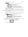
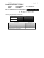
13.- APPENDIX
13.1.- Appendix A: Four quadrant measuring method in the CVM-BDM
Example of the phase
difference between
voltage and current
30º
300º
210º
120º
Active power
kW or kW.h
kW
kW
kW
kW
+
+
---
Reactive power
kvar or kvar. h
kvar L
kvar C
kvar L
kvar C
+
+
---
P. F.
+
-+
--
53
-----
CVM-BDM supply network analyzer --------
--- Page Nº
54
13.2.- Appendix B: Second SETUP of the CVM-BDM
A second SETUP menu is accessible in order to perform the configuration of
the CVM-BDM with other features different from factory-supplied ones.
To access this menu proceed as follows:
- Being the CVM-BDM powered off, simultaneously press "display", "max"
and "min" keys.
- Holding these keys pressed, power the CVM-BDM on.
Following messages will be then shown on display:
a.- COMMUNICATION PROTOCOL : MODBUS
SET
PROT
Protocol :
BUS
MODBUS (c) (BUS) protocol
-
"display" key: to validate the choice and pass to the next setup screen:
b.- Setting communication parameters
SET
Cdef
default configuration
NO
"max" key to switch from NO / YES
-
If YES is chosen: the configuration is set at 001 / 9600 / 8 bits / N / 1 bit
-
If NO is chosen, then following options successively appear on display:
- n PER
:
Peripheral No. 001 to 255
- Baud 1
:
Baud rate 1200 – 2400 – 4800 – 9600 – 19200
- Parity
:
No, even, odd
- LEN
:
(length) 8 bits
- Stop bits
:
1 or 2
-----
CVM-BDM supply network analyzer --------
--- Page Nº
55
c.- SETUP locking or unlocking
SET
Up
Unlo
Loc (locked SETUP ) or
Unloc (unlocked)
Use the key "max" to modify the choice.
-
If LOC is set, when the SETUP is accessed configuration parameters can
be then visualized but cannot be modified.
-
To modify the previously set option a 4-digit password is required to be
entered (in case that this password is not correct, this blinks and the
previous menu is again accessed).
CVM-BDM PASSWORD : 1234
To exit this setup mode, the key RESET can be pressed at any moment (WARNING:
if the setup is exited by pressing the key RESET some latest modifications might not
be saved into memory) or reach the end of this setup mode.
-----
CVM-BDM supply network analyzer --------
--- Page Nº
56
13.3.- Appendix C: Internal memory reading and setting procedures
13.3.1.- Description
The CVM-BDM is equipped with an 1Mbyte internal memory. So, the
different information recorded by the CVM-BDM into its on-board memory is
distributed between two file types:
− STD file: 1 Mbyte capacity. This file contains all values which are
periodically recorded (V, I, W, Hz ...).
− EVE file: 1 kbyte capacity. File which contains all incidents referred to the
CVM-BDM power supply (power supply on/off)
Parameters to be recorded by the CVM-BDM into the STD file are userprogrammable, thus, the memory autonomy will depend both on the number of
parameters to be saved (up to a maximum of 130 parameters) and the recording
period
The below table shows the method to calculate the memory autonomy
according to the number of parameters selected to be saved:
File type
Maximum size
Register size
*.STD
1 Mbyte
6 + (4 * Parameter No.)
*.EVE
1 kbyte
6 bytes
* The energies count like two parameters
Register No.
1000000
6 + (4 * Parameter No.)
170 Events
Example of STD file length: For 20 parameters and 15-minute recording period.
1000000
1000000
Re gister No. =
=
= 11627
6 + (4 * Parameter No.) 6 + (4 * 20)
Length =
11627
= 2906 hours = 121 days
4
-----
CVM-BDM supply network analyzer --------
--- Page Nº
57
13.3.2.- Internal memory setting for data collection purposes
The PC software permits the user to precisely set the power meter to optimize
the use of its internal memory for data collection purposes.
Thus, below listed user-programmable fields can be defined to establish the
recording process into the STD file:
− Recording period.
− Parameters to be saved into memory.
− Trigger conditions.
Regardless the configuration of the recording process, this will never affect the
EVE file recording actions.
13.3.2.1.- Recording period
Integration period for data recording into memory of all user-selected
parameters (1-240 minutes).
Values will be saved at the end of the recording period together with the
time/date of the period beginning moment.
13.3.2.2.- Parameters to be saved into memory
The memory autonomy greatly depends on the number of parameters
selected to be saved (up to a maximum of 130 parameters).
By means of the Power-Vision software, every discrete parameter to be saved
into memory can be particularly chosen.
File type
*.STD
Maximum size
1 Mbyte
Register size
6 + (4 * Parameter No.)
Register No.
1000000
6 + (4 * Parameter No.)
For the right calculation of the memory autonomy, the user must take into
account that every energy parameter count like two parameters, since its information
fills 8 bytes instead of 4 bytes.
-----
CVM-BDM supply network analyzer --------
--- Page Nº
58
13.3.2.3.- Trigger
You can set certain conditions (Trigger) so that values are saved into memory
only when these conditions are met.
Two types of trigger conditions are available:
1. Level trigger: Setting of a parameter to be used as a trigger condition, as
well as its maximum and minimum range-limiting values.
2. Time trigger (Start/ End date): Setting of dates and times for the starting
and ending actions of the recording process.
Note:
-
To record values into memory, the two user-defined TRIGGER conditions must be
simultaneously met, if any condition is not met, then no data will be saved into memory. If
the trigger conditions are disabled, then values will be always saved into memory
according the user-defined recording period.
-
If the trigger conditions are simultaneously met at any moment within the selected
recording period, then average values over all the period will be saved into memory.
•
LEVEL TRIGGER:
Setting of a parameter to be used as a trigger condition, as well as its
maximum and minimum range-limiting values.
- Parameter: Choice of the parameter to be used as the trigger
condition for data recording actions:
Vp-p, Vp-n, A, kW, kvarL, kvarC, PF, Hz, kVA... and None.
- Maximum: Setting the maximum value to be controlled.
- Minimum: Setting the minimum value to be controlled.
Note:
-
Maximum and minimum values set are only enabled if any trigger parameter has been
previously selected.
Values will be saved into memory when either the instantaneous value of any of the three
phases (L1, L2 or L3) or the three phase value of the selected parameter is higher than
the maximum or lower than the minimum set value.
CVM-BDM supply network analyzer --------
-----
•
--- Page Nº
59
TIME TRIGGER:
Setting of dates and times for the starting and ending actions of the recording
process
-
Start: Starting date for the recording process into the STD file.
-
End: Ending date for the recording process into the STD file.
Note:
-
If only START/END times are set (two dates set to zero), then the defined
recording period will be daily repeated.
All required information about the Software operation
can be found in the CD