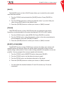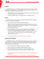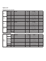
1
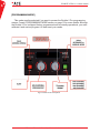
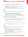
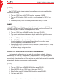
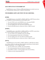
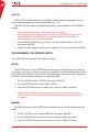
ECOBITE II Pro Electronic spreader controller Manual version 4.4 SPREADING Take control 29, rue Giroux, Québec, QC, Canada, G2B 2X8 T. 418 847 6344 F. 418 847 4851 aceelectronic.ca ECOBITE II PRO V. 4.4 User manual TABLE OF CONTENTS GENERAL PRESENTATION 5 CONSOLE5 REPORTS5 FUNCTIONING MODE 5 OPERATING MODE 7 MANUAL MODE 7 AUTOMATIC MODE 8 MAX MODE 8 FAULT MESSAGES 8 LOSS OF CONVEYOR SPEED SIGNAL 8 OVERSPEEDING8 INSUFFICIENT HYDRAULIC CAPACITY 9 PROGRAMMING MODE 10 CALIBRATION11 CALIBRATION OF THE TRANSMISSION PULSE TO DISTANCE RATIO 11 CALIBRATION OF THE CONVEYOR SPEED 12 CALIBRATION OF CONVEYOR FLOW RATE 13 SPINNER WIDTH CALIBRATION 14 PROGRAMMING15 ENABLING MATERIAL TYPE AND NAME LABELING 15 CHOICE OF MODE USED TO CALCULATE SPREADING 16 PROGRAMMING LIMITS AND STEPS FOR EACH MATERIAL 17 PROGRAMMING THE SPREAD WIDTH 18 PROGRAMMING THE BLAST FUNCTION 19 SUPPLEMENTARY FUNCTIONS 21 ACE, Accent Electronic Controls, visit our website www.aceelectronic.ca 3 4 ECOBITE II PRO V. 4.4 User manual TABLE OF CONTENTS (ANNEXES) ANNEX I - ECOBITE II PRO VERSION 4.4 PROGRAMMING SHEET ANNEX II - PROGRAMMING MENU OVERVIEW ANNEX III - CALIBRATION Chart ANNEX IV - COUNTER MENU ANNEX V - OPRERATION DATA MANAGEMENT : INFOBITE SYSTEM ANNEX VI - TECHNICAL SPECIFICATIONS ANNEX VII - INSTALLING THE CONTROLLER SPEED CABLE ANNEX VIII - ELECTRICAL PLAN ACE, Accent Electronic Controls, visit our website www.aceelectronic.ca 26 29 32 33 34 36 37 38 ECOBITE II PRO V. 4.4 User manual GENERAL PRESENTATION ECOBITE II Pro is a simple and economical electronic spreader controller for dry material applications (salt, sand, gravel, etc.). It controls the uniform application of these materials independently of spreader types or vehicle speed. CONSOLE The ergonomic design of the console allows the operator to: • • • • Choose spreader settings between up to 4 material types; Define the solid material spreading rate (typically from 5 to 995 kg/km); Adjust the spinner spreading pattern (typically from 0.5 to 9.5 meters); Momentarily blast a higher quantity of material in accordance with preset parameters. REPORTS There exists two methods of obtaining activity reports : The [MNUCNT] function recuperates spreader data manually after each operation. Consult ANNEX IV on page 33 for details. )) This function is not factory activated. Detailed activity reports can also be produced to analyze spreading operations when the Ecobite II Pro controllers are fitted with ACE’s optional Infobite GPS data loggers. The Infobite software generates reports for several vehicles and/or operators and to work in multi user mode. To do so, it requires linking the Infobite data collection system to the Ecobite II Pro controller (see ANNEX V on page 34). The Infobite GPS automatically downloads the data collected all along the travelled route right to your computer when the vehicle returns to its base. FUNCTIONING MODE The ECOBITE II Pro spreader controller incorporates two modes: [OPERATING MODE] This mode is selected for the regular activities of the spreader, like spreading salt on the road. Consult OPERATING MODE section on page 7 for more details. ACE, Accent Electronic Controls, visit our website www.aceelectronic.ca 5 ECOBITE II PRO V. 4.4 User manual 6 [PROGRAMMING MODE] This mode must be selected if you want to access the Ecobite II Pro programming menus. Consult PROGRAMMING MODE section on page 10 for more details. Although the Ecobite II Pro is shipped factory programmed and is instantly operational, you must calibrate it and custom program it to best meet your needs. Fig.1 Ecobite II Pro front panel ACE, Accent Electronic Controls, visit our website www.aceelectronic.ca ECOBITE II PRO V. 4.4 User manual OPERATING MODE • Start the controller by pressing the (PAUSE) button on the unit. • When starting up, the controller will display the last material spread. You can select a different material type with the material switch (MAT. TYPE) or keep the same material. The spreader will not discharge any material while on (PAUSE). • To start spreading, press the (PAUSE) button once. • To stop spreading, press the (PAUSE) button once.The display will show «PAUSE». • To close the controller, hold the (PAUSE) button pressed for two seconds. • Select either the manual [MAN] or automatic mode [AUTO] with (AUTO/MAN) switch. The controller will show «AUTO» or «MANUAL» on its display according to the selected mode. )) Turning the vehicle key ignition to the OFF position will also shutdown the controller. MANUAL MODE In manual mode, the conveyor and spinner speeds are directly controlled by the position of their respective knob (CONV) and (SPIN). The controller directly sets the hydraulic valve openings according to the knob position. The conveyor span setting goes from 0 to 100 as the spinner setting goes from 0 to the programmed maximum width, factory set to 3.0. )) By default, the manual mode does not allow spreading while the truck is moving. To allow spreading in manual mode while moving, see [MANUAL] section on page 24. )) While in manual mode, the controller considers the truck is moving at 45 km/h. )) Use this mode for unloading the spreader. ACE, Accent Electronic Controls, visit our website www.aceelectronic.ca 7 ECOBITE II PRO V. 4.4 User manual 8 AUTOMATIC MODE In automatic mode, the controller takes the vehicle ground speed combined with the conveyor (CONV) knob position to calculate the spreading rate. However, the spread width is independent to speed and depends on the (SPIN) knob position only. MAX MODE The (MAX) button will increase the spread rate to perform a blast over a short distance. By pressing the red (MAX) button you will start the blast function for a programmed delay. You may stop the blast anytime by pressing the (MAX) button a second time. )) The programmed rate and width will flash on the display while the blast is on. )) In manual mode the word «MAX» and the spread width will flash on the dis play for the length of the blast. )) An audible signal announces the end of the blast operation. FAULT MESSAGES Fault messages are displayed when the controller is unable to provide the requested amount of material. Those messages are described here below. LOSS OF CONVEYOR SPEED SIGNAL The controller will start to beep and the spread rate on screen will indicate «0». After a few seconds, the display will indicate «DPCONV» (Conveyor breakdown mode). This mode allows the controller to continue spreading operations without the conveyor speed signal. Spreading remains proportional to ground speed and takes into account the chosen spread rate and material type. )) Every controller shutdown resets the controller to normal mode. )) The controller will automatically return into breakdown mode until the conveyor speed sensor problem is solved. )) The «DPCONV» message is displayed every 10 km, with a small audible alarm to keep the operator aware that the controller operates in breakdown mode. OVERSPEEDING The controller beeps slowly while this condition lasts. This means that the spreading operation is done at higher speed than the preprogrammed maximum speed. The display indicates no special message. )) Reduce the speed of the vehicle ACE, Accent Electronic Controls, visit our website www.aceelectronic.ca ECOBITE II PRO V. 4.4 User manual INSUFFICIENT HYDRAULIC CAPACITY The controller beeps rapidly. The display indicates the actual spread rate, not the set rate. This indicates that the hydraulic system is of insufficient capacity to spread at the rate and speed required. )) Reduce the speed of the vehicle and/or spreading rate. ACE, Accent Electronic Controls, visit our website www.aceelectronic.ca 9 ECOBITE II PRO V. 4.4 User manual 10 PROGRAMMING MODE Before using the vehicle and controller it is necessary to match the controller with the vehicle. This is performed in the following programming mode. WARNING ! During the programming procedure certain menus will cause conveyor and/or spinner movement. This is because the controller is applying the factory programmed values or the values of a previous calibration. MAKE SURE ANY CONVEYOR AND/OR SPINNER MOVEMENT IS WITHOUT DANGER. 1. To have access to the programming mode, press the (PAUSE) and (MAX) buttons simultaneously for two seconds. 2. Anaudiblealarmconfirmsthatyouhaveenteredtheprogrammingmode.The programming menu «CONFIG» appears on the display. 3. If the controller requests an access code, see [CODE] section on page15. 4. Tochooseanyoptionintheprogrammingmenu,turnthe(CONV)knobto chooseanoption.Confirmyourchoicebypressingthe(PAUSE)button,or the(MAX)buttontocancelitorbygoingbackonestep. The programming mode allows you to : • Calibrate the controller (it is recommended to do so every fall). See CALIBRATION section on page 12 for more details. • Programthecontrollertosatisfytheoperatorandsupervisor’sneeds.See PROGRAMMING section on page 15 for more details. • Activate certain additional functions. See SUPPLEMENTARY FUNCTIONS section on page 21 for more details. ACE, Accent Electronic Controls, visit our website www.aceelectronic.ca ECOBITE II PRO V. 4.4 User manual Fig.2 ECOBITE II Pro front panel button functions CALIBRATION CALIBRATION OF THE TRANSMISSION PULSE TO DISTANCE RATIO The[>SPEED]menuallowsthecalibrationofthepulse/distanceratio.Thecontroller can then determine the number of pulses the transmission sends when the vehicule travelsapredefineddistance. [SPDTST] The [SPDTST] function allows you to verify the correctness of the speed calibration. Turnthe(CONV)knobtothe[SPDTST]function,thenpressthe(PAUSE)button. Whenmovingthevehicle,thecontrollerwillindicatethevehiclespeedinkm/has currently calibrated. If the vehicle speed displayed in the [SPDTST] function is incorrect, therearetwowaystocalibratethevehicledistance;the«1km»methodorthe«real time» method (see SPDSET section below). Use only one of those methods. ACE, Accent Electronic Controls, visit our website www.aceelectronic.ca 11 ECOBITE II PRO V. 4.4 User manual 12 [DSTSET] The [DSTSET] function allows you to calibrate the speed of the vehicle by the distance. 1. Place the vehicle at the beginning of the measured 1 km distance. 2. Turn the (CONV) knob to [SPDSET] option, then press (PAUSE). 3. The controller display will indicate «START». 4. At the beginning of the measured 1 km distance, press (PAUSE). 5. Drive the vehicle through the 1 km distance. 6. The controller counts the pulse retrieved from the transmission. 7. Once the km is completed, press (PAUSE) to complete the calibration. The message «SAVED» will show on display. [SPDSET] The [SPDSET] function allows you to calibrate the vehicle speed in real time (using a GPS or a similar device) 1. Turn the (CONV) knob to [SPDSET] function, then press (PAUSE). 2. On the display’s left, the controller will indicate the vehicle speed as currently calibrated, and the desired calibration speed on the right side. 3. Turn the (SPIN) knob to the desired calibration speed. If, for example, you want to run 40 km/h during calibration, then turn the (SPIN) knob to 40. 4. When the real vehicle speed is stabilized at 40 km/h, press the (PAUSE) button to finish the calibration procedure.The display then show «SAVED». )) The maximum allowable number of pulses per km is 90.000. Do not exceed this limit. CALIBRATION OF THE CONVEYOR SPEED The [>CONV] menu lets you match hydraulic and electronic system components. [MIN] The [MIN] function in the [>CONV] menu allows you to set the minimum conveyor speed and thus achieve a speedy conveyor reaction. ACE, Accent Electronic Controls, visit our website www.aceelectronic.ca ECOBITE II PRO V. 4.4 User manual 13 1. Turn the (CONV) knob to [MIN] function, then press (PAUSE). 2. Turn the (CONV) knob to increase the electric current until the conveyor just starts to move. 3. When the conveyor starts moving, take note of the pulse count indicated on the display and write it down on ANNEX I, page 26. 4. Press the (PAUSE) button to confirm your minimum speed, or (MAX) to cancel. [MAX] The (MAX) function in the [>CONV] menu allows you to limit the conveyor speed to a maximum. 1. Turn the (CONV) knob to (MAX) function, then press (PAUSE). 2. Turn the (CONV) knob until the maximum desired speed is reached. 3. Take notes of the pulse count displayed on the calibration chart on page 32. 4. Press the (PAUSE) button to confirm your maximum speed, or (MAX) to cancel. CALIBRATION OF CONVEYOR FLOW RATE )) It is recommended to do this calibration procedure with salt and at least one other material, as their respective material flow might differ. The following procedure is the one for the material [SALT]. The procedure is identical for all others materials. • Complete the calibration chart as illustrated in ANNEX III on page 32. In the following paragraph, [SALT] is used to calibrate the conveyor of a salt spreader. [CALIBR] Before starting the actual calibration procedure, please check that the following preparations are done: 55 There is sufficient material in the hopper to fill the calibration box; 55 The gate is set to the correct height for the material to be calibrated, and noted in the calibration chart, page 32; 55 The cross conveyor has material on it so material starts to fill the form as soon as the conveyor starts to move; 55 The measuring form is placed so ALL material coming from the conveyor stays in it. ACE, Accent Electronic Controls, visit our website www.aceelectronic.ca ECOBITE II PRO V. 4.4 User manual 14 1. Turn the (CONV) knob to [CALIBR] function in the [>SALT] menu, then press (PAUSE). 2. The display indicates «START». It is ready to fill the bottomless measuring form of usually ¼ cubic meter. 3. Start the calibration process by turning the (CONV) knob until the conveyor runs at its usual operating speed. 4. You can adjust the spinner speed to the lowest speed by turning the (SPIN) knob to its minimum position, so no material will be thrown outside the box. 5. When the form is full, turn the (CONV) knob to the left until the conveyor stops. 6. Write down the number of revolutions and the programming weight indicated at the right side of the display in the appropriate case of the calibration certifi- cate of the spreader (see ANNEX III, page 32). 7. Press the (PAUSE) button to confirm your choice, or (MAX) to cancel. 8. A verification procedure exists. See «TEST» section on page 23. )) Make sure the trap height is the one for salt. )) You may suspend the calibration procedure any time by turning the (CONV) knob to the zero position, which stops the conveyor. You may turn the conveyor speed up or down at will. Use this feature to fill the calibration form until the material is exactly level. )) You may cancel the calibration any time by pressing the (MAX) button. )) During the calibration procedure the display will indicate the hydraulic motor RPM on the left and the total of conveyor sensor pulses on the right. The factory default material weight is for ¼ cubic meter. Materials Weight Salt 325kg Sand 420kg Mat A 373kg Mat B 373kg Chart 1 Factory default material weight for ¼ cubic meter SPINNER WIDTH CALIBRATION The [>WIDTH] menu allows you to calibrate the spread width. )) It is recommended to calibrate the spread width using salt, so it will be as precise as possible. ACE, Accent Electronic Controls, visit our website www.aceelectronic.ca ECOBITE II PRO V. 4.4 User manual [CALIBR] The [CALIBR] function in the [>WIDTH] menu allows you to establish two reference widths : 0.5 and 3.0 meters. Perform the sequences below to calibrate the width: 1. Turn the (CONV) knob to [CALIBR] function, then press (PAUSE). 2. Turn the (CONV) knob, so the conveyor moves some material to the spinner. 3. Turn the (SPIN) knob to increase the speed of the spinner until it covers a 0.5 meter wide area. Press (PAUSE) to confirm. 4. Repeat the operation for 3.0 meters width calibration. The display will show «SAVED». )) During the width calibration procedure, the controller will indicate the current sent to the spinner solenoid coil on the right side of the display. Note this number in the calibration chart of the spreader in ANNEX III on page 32. PROGRAMMING Programming the controller establishes various limits and modes required for the controller operation. The operator will then use the spreader under defined limits and expected results. Before starting to program a controller, the person in charge of operations must complete ANNEX I on page 26 to establish the programming data. WARNING ! Make sure that any conveyor or spinner movement during programming is without danger. It is always possible to stop any conveyor and/or spinner movement by hitting the (MAX) button. ENABLING MATERIAL TYPE AND NAME LABELING The [>SALT], [>SAND], [>MAT A] or [>MAT B] menus allow you to enable and name the materials you wish to use amongst the four potentially available for spreading. ACE, Accent Electronic Controls, visit our website www.aceelectronic.ca 15 ECOBITE II PRO V. 4.4 User manual 16 [ACTIVE] The [ACTIVE] function in each material menu allows you to render available this material for spreading. 1. Turn the (CONV) knob to [ACTIVE] function, then press (PAUSE). 2. Turn the (SPIN) knob to [ON] if you wish to use the material, or [OFF] if you don’t. 3. Press the (PAUSE) button to confirm your choice, or (MAX) to cancel. [NAME] The [NAME] function allows you to replace the factory default names [>SALT], [>SAND], [>MAT A] and [>MAT B] menus with the name of your choice. However, the new name may have a maximum of six alphanumeric digits. 1. Turn the (CONV) knob to [NAME] function, then press (PAUSE). 2. The current material name is shown on display and the first digit of the name is flashing. 3. Turn the (SPIN) knob to the first letter of the new name. 4. Press (PAUSE) to confirm the first digit, and then repeat the operation for the following characters. If you have less than six digits in your name, press (PAUSE) repeatedly to leave blanks at the end. 5. When the sixth digit is confirmed, «SAVE» will flash on screen before it re turns to the [NAME] function. Your new name is now stored in the memory and will show on display during operations. CHOICE OF MODE USED TO CALCULATE SPREADING It is important to define which unit you wish the controller to work with. In kg/km, a standard unit, the flow rate is independent to the spread width. If the operator wishes to spread the same quantity on a larger width, he must change the width and flow rate proportionally. However, more and more services are working with g/m2, which does this automatically, allowing more accurate spreading results. [M EPD] 1. Turn the (CONV) knob to [MODE] MENU, then press (PAUSE). 2. Select [M EPD] with the (CONV) knob, then press (PAUSE). 3. Select [kg/km] or [g/m2] with the (SPIN) knob, then press (PAUSE). 4. Exit menu with (MAX). ACE, Accent Electronic Controls, visit our website www.aceelectronic.ca ECOBITE II PRO V. 4.4 User manual QUICK VERIFICATION OF PROGRAMMED UNIT Set (SPIN) knob to zero. If 0.0 above (SPIN) knob flashes, the controller is set to g/ m2. This flashing also indicates that no material is being spread. PROGRAMMING LIMITS AND STEPS FOR EACH MATERIAL [KK/MIN] The [KK/MIN] function in the [>SALT], [>SAND], [>MAT A] or [>MAT B] menus allows you to establish a minimum spread rate for each material used. 1. Turn the (CONV) knob to the [KK/MIN] function, then press (PAUSE). 2. The current programmed value shows on the display. 3. Turn the (CONV) knob to the new minimum spread rate value. 4. Press the (PAUSE) button to confirm your choice, or (MAX) to cancel. [KK/MAX] The [KK/MAX] option in the [>SALT], [>SAND], [>MAT A] or [>MAT B] menus allows you to set the maximum spread rate for each material used. 1. Turn the (CONV) knob to [KK/MAX], then press (PAUSE). 2. The current programmed value shows on the display. 3. Turn the (CONV) knob to the new maximum spread rate value. 4. Press the (PAUSE) button to confirm your choice, or (MAX) to cancel. [STEPS] The [STEPS] option in the [>SALT], [>SAND], [>MAT A] or [>MAT B] menus allows you to define variation for each step when changing the spread rate for each material. Available choices are 5, 10, 25, 50 and 100 kg/km. 1. Turn the (CONV) knob to (STEPS), then press (PAUSE). 2. The current programmed step value shows on the display. 3. Press (MAX) to confirm, or turn the (CONV) knob to the new setting. 4. Confirm your choice by pressing (PAUSE). ACE, Accent Electronic Controls, visit our website www.aceelectronic.ca 17 ECOBITE II PRO V. 4.4 User manual 18 [LIQ PC] The [LIQ PC] function allows you to attribute a liquid weight percentage to one or many materials depending on their solid weight (ex. 5%). This ratio will automatically calculate the quantity of liquid spread in the INFOBITE reports. )) This programming is fixed. The operator cannot modify it. )) By distinguishing the name of a dry material (ex. DRYSAND) from that of a humid material (ex. HUMSAND), You give the operator the possibility to choose wether or not to wet the materials. 1. In the MATERIAL MENU of your choice, turn the (CONV) knob to «PC LIQ», then press (PAUSE). 2. Display the percentage of wetness (0 by default). Confirm by pressing (PAUSE). PROGRAMMING THE SPREAD WIDTH The [>WIDTH] menu programs the spinner features. [STOP] The [STOP] option in the [>WIDTH] menu allows you to stop the spinner when the truck stops, or to have it rotate as long as the controller is in the operating mode. When set to [ON], the spinner will stop and start simultaneously with the conveyor. When set to [OFF] it will run while the spinner is in operating mode. 1. Turn the (CONV) knob to (STOP), then press (PAUSE). 2. Turn the (SPIN) knob to choose [ON] or [OFF]. 3. Press the (PAUSE) button to confirm your choice, or (MAX) to cancel. )) Certain valve models require the operation of the conveyor for the spinner to work. Hence, it will be impossible to operate the spinner when the vehicle is stopped. [MAX/W] The [MAX/W] option in the [>WIDTH] menu allows you to set the maximum spread width. 1. Turn the (CONV) knob to select [MAX/W], then press (PAUSE). 2. Turn the (SPIN) knob to enter the maximum spread width to program. 3. Press the (PAUSE) button to confirm your choice, or (MAX) to cancel. ACE, Accent Electronic Controls, visit our website www.aceelectronic.ca ECOBITE II PRO V. 4.4 User manual [STEPS] The [STEPS] option in the [>WIDTH] menu lets you choose the variation step when changing the spinner speed. Choices are 0.5 or 1.0 meter. 1. Turn the (CONV) knob to [STEPS], then press (PAUSE). 2. Turn the (CONV) knob to choose between 0 and 1.0 meter. 3. Press the (PAUSE) button to confirm your choice, or (MAX) to cancel. PROGRAMMING THE BLAST FUNCTION The (MAX) button engages the blast function, which is a higher spread rate during a short distance. When the operator presses the (MAX) button, the controller will apply the programmed rate, width and duration as well as the speed of the vehicle or the theoretical minimum speed to perform the blast. When the blast is running the display will flash the blast rate, or (MAX) if operating in manual mode. An audible signal indicates the end of the blast function. The [>MAX] menu allows you to program the blast for each material. See [SALT], [SAND], [MAT A], [MAT B] section below. [SALT], [SAND], [MAT A], [MAT B] The [SALT] function in the [>MAX] menu allows you to choose the rate and width when blasting with salt. (The other materials are identical) 1. Turn the (CONV) knob until «SALT» is displayed, then press (PAUSE). 2. Turn the (CONV) knob to adjust the blast rate. 3. Turn the (SPIN) knob to choose the blast width. 4. Press the (PAUSE) button to confirm your choice, or (MAX) to cancel. )) The blast rate may be set between 0 and 995 kg/km, and the width between 0.5 and 9.5 meters. )) See WIDTH section on page 20 if you want the spinner to continue turning at its regular rate during blast. ACE, Accent Electronic Controls, visit our website www.aceelectronic.ca 19 ECOBITE II PRO V. 4.4 User manual 20 [MANMAX] The [MANMAX] function in the [>MAX] menu allows you to set the conveyor and spinner speeds for the manual mode. 1. Turn the (CONV) knob to [MANMAX] function, then press (PAUSE). 2. Turn the CONV knob to set the conveyor speed. 3. Turn the SPIN knob to set the width in meters. 4. Press the (PAUSE) button to confirm your choice, or (MAX) to cancel. [DELAY] The [DELAY] function in [>MAX] menu allows you to set the run time for a blast. 1. Turn the (CONV) knob to select [DELAY] function, then press (PAUSE). 2. Turn the (CONV) knob to set the number of minutes of the blast. 3. Turn the (SPIN) knob to set the number of seconds of the blast. 4. Press the (PAUSE) button to confirm your choice, or (MAX) to cancel. )) The [DELAY] is adjustable between 0 seconds and 99min, 59sec. [MIN/S] When the truck moves at very low speed, the blast may not necessarily supply sufficient material. In this case the controller uses a theoretical minimum speed to overdose the blast. This theoretical speed will be considered the vehicle speed as long as it moves slower than this reference speed. The [MIN/S] function lets you set this speed between 0 and 50 km/h. 1. Turn the (CONV) knob to [MIN/S] function, then press (PAUSE). 2. Select you minimum speed by turning the (SPIN) knob. 3. Press the (PAUSE) button to confirm your choice, or (MAX) to cancel. )) The factory setting of this minimum speed is 20 km/h. ACE, Accent Electronic Controls, visit our website www.aceelectronic.ca ECOBITE II PRO V. 4.4 User manual 21 [CONT] The [CONT] function in the [>MAX] menu lets you choose to enable the blast function even when the vehicle is stopped. 1. Turn the (CONV) knob to [CONT] function, then press (PAUSE). 2. Turn the (SPIN) knob to [ON] to allow blasting when stopped, or [OFF] if you wish to disable the blast with the vehicle stopped. 3. Press the (PAUSE) button to confirm your choice, or (MAX) to cancel. [WIDTH] The [WIDTH] function in the [>MAX] menu allows you to choose from three different spread width control manners during a blast. • The spread width during a blast is always the width programmed in the [SALT], [SAND], [MAT A], [MAT B] function, see on page 19. This is the [PERM] control spreading. • The spread width during a blast is the width programmed in the [SALT], [SAND], [MAT A], [MAT B] function, see on page 19. However it is possible to vary it through the (SPIN) knob. This is the [TEMP] control spreading. • The spread width during a blast is the same as during regular spreading operations. This is the [OFF] control spreading. 1. Turn the (CONV) knob to [>WIDTH] menu, then press (PAUSE). 2. By turning the (SPIN) knob, select one of [PERM], [TEMP] or [OFF]. 3. Press the (PAUSE) button to confirm your choice, or (MAX) to cancel. SUPPLEMENTARY FUNCTIONS [LANGUAGE] : ENGLISH The [LANGUAGE] function allows you to choose the language for the display. Those languages are either French or English. 1. Select the [LANGUAGE] function by turning the (CONV) knob. Press (PAUSE) to confirm. 2. Turn the (SPIN) knob to select [FR] for French or [EN] for English. 3. Press (PAUSE) to confirm, or (MAX) to cancel. ACE, Accent Electronic Controls, visit our website www.aceelectronic.ca ECOBITE II PRO V. 4.4 User manual 22 [MAXSPD] The [MAXSPD] function allows you to set the maximum speed permitted during spreading operations. If the maximum permitted speed is exceeded during a spreading operation, the controller will slowly beep. 1. Turn the (CONV) knob to select the [MAXSPD] function, then press (PAUSE). 2. Select the maximum allowed speed by turning the (SPIN) knob (0 to 99 km/h) 3. Press (PAUSE) to confirm you choice, or (MAX) to cancel. )) When 0 km/h is selected, the audible signal is deactivated. [CODE] 4 DIGITS The [CODE] function allows you to add or change the 4 digit access code to the programming mode. The factory programmed code 1234 is not requested when entering the programming mode. Any other code will be requested to enter the programming mode. 1. Turn the (CONV) knob to select the [CODE] function, then press (PAUSE). 2. Turn the (SPIN) knob to choose the first number, from 1 to 9, then press (PAUSE) to move on to the second number. Repeat the operation until all four numbers are confirmed. 3. Repeat the same number the same way, then press (MAX) to return to the main menu. 4. Note the code in the appropriate box on the calibration chart )) If you forget the new programmed access code, only an ACE technician will be able to unlock the controller. [F-SET] The [F-SET] function allows you to reset the controller to its factory settings. 1. Turn the (CONV) knob to select [F-SET] function, then confirm by pressing the (PAUSE) button. 2. Turn the (SPIN) knob to select [NO] or [YES]. Selecting [NO] will avoid the factory reset and [YES] will apply the reset. 3. Press (PAUSE) to confirm the factory reset, or (MAX) to cancel. )) This operation will erase your entire setup.You will have to redo the calibration. ACE, Accent Electronic Controls, visit our website www.aceelectronic.ca ECOBITE II PRO V. 4.4 User manual 23 [VALVE] The [VALVE] function in the [>VALVE] menu allows you to select the valve model used with the controller. 1. Turn the (CONV) knob and select the [VALVE] function. Press (PAUSE) to confirm. 2. Turn the (SPIN) knob until you find your particular valve. If you don’t find your valve, choose [DEF] which is the default value. 3. Press the (PAUSE) button to confirm your choice, or (MAX) to cancel. [FRQ HZ] The [FRQ HZ] function in the [>VALVE] menu lets you select the valve driver frequency as recommended by the valve manufacturer (225 HZ for ACE valves). 1. Turn the (CONV) knob to select [FRQ HZ]. Press (PAUSE) to confirm. 2. Turn the (SPIN) knob to select the frequency close to the valve manufacturer’s recommendation, the press (PAUSE) to confirm. 3. Press the (PAUSE) button to confirm your choice, or (MAX) to cancel. [BOOST] [>CONV] MENU The [BOOST] function in the [>CONV] menu reduces the delay upon startup until material reaches the spinner. When the vehicle starts moving the conveyor moves rapidly during a short period of time in order to bring material to the spinner as soon as possible. You may program this conveyor speed and its duration. 1. Turn the (CONV) knob to [BOOST] function, then press (PAUSE). 2. Turn the (CONV) knob to set the desired conveyor speed. 3. Turn the (SPIN) knob to set the desired duration of this boost. 4. Press the (PAUSE) button to confirm your choice, or (MAX) to cancel. • You can adjust the duration between 0.5 and 10 seconds, by 0.5 second increments. ACE, Accent Electronic Controls, visit our website www.aceelectronic.ca ECOBITE II PRO V. 4.4 User manual 24 [M/PPR] The [M/PPR] function in the [>CONV] menu lets you adjust the number of pulses produced by the speed sensor of the conveyor hydraulic motor (30 for ACE).Turn the (CONV) knob to [M/PPR], then press (PAUSE). 1. Turn the (SPIN) knob to the number of pulses produced by the make and model of hydraulic motor used on your machine. 2. Press the (PAUSE) button to confirm your choice, or (MAX) to cancel. [TEST] The [TEST] function in the material menus [SALT], [SAND], [MAT A] or [MAT B] allows you to validate the calibration. 1. Turn the (CONV) knob to [TEST], then press (PAUSE). 2. Enter the amount of material in kilograms that will be used for the test. This quantity should be identical to the amount of material used to fill the calibration box during the calibration procedure. 3. Press the (PAUSE) button 4. Turn the (CONV) knob to set the conveyor speed. Turn the (SPIN) knob to set a spinner speed that ensures all material falls into the box. When the amount of material discharged reaches the value set for the [TEST], the conveyor will stop. The display will show: «TEST COMPLETED» and an audible signal will sound. )) The test form must be level full for the test to be successful. [BOOST] [>WIDTH] MENU The [BOOST] function in the [>WIDTH] menu allows you to increase the spinner speed during a short lap upon startup, especially with small displacement spinner hydraulic motors. To program the speed that will be added to increase the regular speed, follow the sequence above. 1. Turn the (CONV) knob to [BOOST], then press (PAUSE). 2. Turn the (CONV) knob to adjust the additional spinner speed. 3. Turn the (SPIN) knob to set the duration of this spinner speed boost. 4. Press the (PAUSE) button to confirm your choice, or (MAX) to cancel )) The extra spinner boost speed is added to the spinner speed setting of the (SPIN) knob. )) The duration may be set from 0 to 10 seconds in 0.5 second increments. ACE, Accent Electronic Controls, visit our website www.aceelectronic.ca ECOBITE II PRO V. 4.4 User manual 25 [MANUAL] The [MANUAL] function in the [>MODE] menu allows you to use the manual mode during normal spreading operations, or make it the «discharge» available for a stationary vehicle. When manual mode is off, the controller will always assume the operation speed is of 45 km/h. 1. Select the [MANUAL] function by turning the (CONV) knob. 2. By turning the (SPIN) knob, select [ON] to limit the use of the manual mode for unloading only, or choose [OFF] to make it available for normal spreading operations. 3. Press (PAUSE) to confirm your choice, or (MAX) to cancel. [MNUCNT] The [MNUCNT] function in the [>MODE] menu allows you to activate the counters inbuilt into the controller. Factory default, this function is inactive. The list of information and how to access it is explained in ANNEX IV on page 33. 1. Turn the (CONV) knob to select [MNUCNT]. Confirm by pressing (PAUSE). 2. Using the SPIN knob, select [ON] to activate the counters, or [OFF] to deactivate them. 3. Press (PAUSE) to confirm your choice, or (MAX) to cancel. ACE, Accent Electronic Controls, visit our website www.aceelectronic.ca ANNEX I - ECOBITE II PRO VERSION 4.4 PROGRAMMING SHEET Spreader Make Type Programming date Year N° Controller Serial N° Name Comments: Settings independent to chosen unit to define spreading MENU VALVE CONV Function Page VALVE FRQ HZ MIN MAX 23 23 12 13 STOP STEPS --- 23 23 24 18 24 24 18 19 22 CODE --- 22 MODE MANUAL MNUCNT 25 25 BOOST M/PPR MAX/W WIDTH MAXSPD BOOST Parameters Factory settings Valve type Remcommended rate Conveyor startup Conveyor speed limit Startup speed boost Length of startup boost Conv. pulse sensors Max width Startup boost Length of boost Automatic stop Variation step Max speed alarm Choosing code to limit access to programming Manual mode Manual data collection DEF 225 HZ 60 180 75 1.0 s 30 3.0 m 5 0.5 s ON 0.5 m 50 km/h Choice of measuring unit KK/KM Possible settings None 14/28/56/112/225/450/900 ON OFF 20 - 120 MIN - 255 0 – 255 0 – 10 10 - 100 0.5 - 9.5 0 - 100 0 - 10 ON - OFF 0.5 - 1.0 0 - 99 km/h ON - OFF ON - OFF Choice of spreading unit MODE M EPD 16 Depending on the unit you have chosen, fill in one of the following pages KK/KM – G/M2 Choice Kg/km unit Programming the materials SALT SAND MAT A MAT B KK/MIN KK/MAX ACTIVE STEPS LIQPC NAME KK/MIN KK/MAX ACTIVE STEPS LIQPC NAME KK/MIN KK/MAX ACTIVE STEPS LIQPC NAME KK/MIN KK/MAX ACTIVE STEPS LIQPC NAME 17 17 16 17 18 16 17 17 16 17 18 16 17 17 16 17 18 16 17 17 16 17 18 16 Min rate Max rate Available material Variation step Liquid % Choosing name of material Min rate Max rate Available material Variation step Liquid % Choosing name of material Min rate Max rate Available material Variation step Liquid % Choosing name of material Min rate Max rate Available material Variation step Liquid % Choosing name of material 50 350 ON 25 0 SALT 200 700 ON 50 0 SAND 150 500 ON 50 0 MAT A 150 500 ON 50 0 MAT B 19 19 19 19 19 19 19 19 20 20 20 20 21 21 Blast rate Blast width Blast rate Blast width Blast rate Blast width Blast rate Blast width % conveyor in blast mode Blast width Blast length Simulated min speed Behaviour when stopped Width behaviour 350 3.0 m 700 3.0 m 500 3.0 m 500 3.0 m 180 3.0 0 mn 20 s 20 km/h ON OFF 0 - 995 MIN - 995 ON - OFF 5/10/25/50/75/100 0(OFF) - 99 6 alphanum. characters 0 - 995 MIN - 995 ON - OFF 5/10/25/50/75/100 0(OFF) - 99 6 alphanum. characters 0 - 995 MIN - 995 ON - OFF 5/10/25/50/75/100 0(OFF)-99 6 alphanum. characters 0 - 995 MIN - 995 ON - OFF 5/10/25/50/75/100 0(OFF) - 99 6 alphanum. characters Programming blasts SALT SAND MAT A MAX (Blasts) MAT B MANMAX DELAY MIN/S CONT WIDTH 0-995 0.5 - 9.5 0-995 0.5 - 9.5 0-995 0.5 - 9.5 0-995 0.5 - 9.5 60 - 255 0.5 - 9.5 0 - 99mn and 0 – 59 s 0 - 50 km/h ON-OFF PERM-TEMP-OFF G/m2 unit Programming the materials SALT SAND MAT A MAT B KK/MIN KK/MAX ACTIVE STEPS LIQPC NAME KK/MIN KK/MAX ACTIVE STEPS LIQPC NAME KK/MIN KK/MAX ACTIVE STEPS LIQPC NAME KK/MIN KK/MAX ACTIVE STEPS LIQPC NAME 17 17 16 17 18 16 17 17 16 17 18 16 17 17 16 17 18 16 17 17 16 17 18 16 Min rate Max rate Available material Variation step Liquid % Choosing name of material Min rate Max rate Available material Variation step Liquid % Choosing name of material Min rate Max rate Available material Variation step Liquid % Choosing name of material Min rate Max rate Available material Variation step Liquid % Choosing name of material 50 350 ON 25 0 SALT 200 700 ON 50 0 SAND 150 500 ON 50 0 MAT A 150 500 ON 50 0 MAT B Blast rate Blast width Blast rate Blast width Blast rate Blast width Blast rate Blast width % conveyor in blast mode Blast width Blast length Simulated min speed Behaviour when stopped Width behaviour 350 3.0 m 700 3.0 m 500 3.0 m 500 3.0 m 180 3.0 0 mn 20 s 20 km/h ON OFF 0 - 995 MIN - 995 ON - OFF 5/10/25/50/75/100 0(OFF) - 99 6 alphanum. characters 0 - 995 MIN - 995 ON - OFF 5/10/25/50/75/100 0(OFF) - 99 6 alphanum. characters 0 - 995 MIN - 995 ON - OFF 5/10/25/50/75/100 0(OFF)-99 6 alphanum. characters 0 - 995 MIN - 995 ON - OFF 5/10/25/50/75/100 0(OFF) - 99 6 alphanum. characters Programming blasts SALT SAND MAT A MAX (Blasts) MAT B MANMAX DELAY MIN/S CONT WIDTH 19 19 19 19 19 19 19 19 20 20 20 20 21 21 0-995 0.5 - 9.5 0-995 0.5 - 9.5 0-995 0.5 - 9.5 0-995 0.5 - 9.5 60 - 255 0.5 - 9.5 0 - 99mn and 0 – 59 s 0 - 50 km/h ON-OFF PERM-TEMP-OFF ECOBITE II PRO V. 4.4 User manual ANNEX II - PROGRAMMING MENU OVERVIEW p.21 p.11 p.23 p.12 ACE, Accent Electronic Controls, visit our website www.aceelectronic.ca 29 ECOBITE II PRO V. 4.4 User manual 30 p.19 p.21 ACE, Accent Electronic Controls, visit our website www.aceelectronic.ca ECOBITE II PRO V. 4.4 User manual p.13 p.22 p.22 p.16 p.22 ACE, Accent Electronic Controls, visit our website www.aceelectronic.ca 31 ANNEX III - CALIBRATION CHART ORGANISATION TRUCK SPREADER CONTROLLER ECOBITE II PRO PROGRAMMING CODE: DIST MENU (page 10) TEST CONV MENU (page MIN : 11) ACE DEFAULT 1 KM : Calibrating the conveyor MENU Displayed name Serial N°: KM / H MAX : (indicate speed) : [CALIBR] procedure results (page 15) Trap height (cm) No of revolutions Weight SALT SAND MAT A MAT B Calibrating the spinner Rotation direction MENU WIDTH MPOINT procedure results (page 12) No of pulses for 0.5 m No of pulses for 3.0 m Clockwise Counterclockwise Done by Date Signature ECOBITE II PRO controller Version 4.3 February 2013 www.aceelectronic.ca ECOBITE II PRO V. 4.4 User manual ANNEX IV - COUNTER MENU The counter menu is only available if the option [MNUCNT] is activated (see section 3.1.1.33 on page 17). THE DATA AVAILABLE FOR EACH MATERIAL ARE : [SPR KM] Kms travelled in spreading mode; [SPR KG] Number of kilograms spread; [MAX KM] Kms travelled in blast mode; [MAX KG] Number of kilograms spread in blast mode; [PAU KM] Kms in pause mode; [OFF KM] Kms travelled with the controller off. THE FOLLOWING PROCEDURE GIVES ACCESS TO THESE DATA : 1. Turn the vehicle ignition key to the [ON] position 2. Without starting the controller, press the [MAT.TYPE] switch to choose the wanted material. 3. Press the (MAX) button to scroll through the data listed above for the material chosen. )) The counter menu closes automatically after ten seconds of non use. )) It is possible to change the material any time by pressing the material selection switch [MAT. TYPE]. THE FOLLOWING PROCEDURE WILL RESET THE COUNTERS : 1. 2. 3. 4. Turn the truck ignition key to the [ON] position Without starting the controller, press the [MAT.TYPE] switch once Then press the [AUTO/MAN] selector switch once. Press the (MAX) button to reset the counters to zero. A message will confirm the operation. )) The counter menu closes automatically after ten seconds of non use. )) All counters reset simultaneously. It is not possible to reset the data for one material only. ACE, Accent Electronic Controls, visit our website www.aceelectronic.ca 33 ECOBITE II PRO V. 4.4 User manual 34 ANNEX V - OPRERATION DATA MANAGEMENT : INFOBITE SYSTEM INFOBITE is a an automated ACE operations data (collection, transmission, restitution and compilation) management system. Inside each vehicle is installed an INFOBITE module. This module automatically records all of the vehicle and operation data, in a programmable way. It also does so each time a change in operation is detected (different rate, blast, pause, etc.). These data are automatically transmitted when the vehicle returns to its centre (or any location equipped with an RF antenna and a computer programmed to collect these data). The INFOBITE software generates reports based on events. Youwillfindeveryparameterusedin operations along with the date and hour of each event as well as corresponding quantities(kmandkg). It also produces custom synthesis reports accordingtoyourspecificneedsand schedule. In a nutshell, it allows you to visualize Google maps afteroperations and to compile results (quantities of materials spread, distance traveled, etc.) for each vehicle according to a determined time frame. ACE, Accent Electronic Controls, visit our website www.aceelectronic.ca ECOBITE II PRO V. 4.4 User manual REPORTS AND SOFTWARE The ECOBITE II Pro controller incorporates counters that indicate the material quantities and distances treated. Refer to the ANNEX IV on page 23. The spreader data may also be exported via a R5232 port located in the back of the controller housing (Infobite GPS option required). The data registered via a GPS tool such as Infobite allow you to visualize all spreader operations with time, date and location stamps for each event. REPORT CONTENT Here above are all the information that the Infobite GPS option will store : 55 Date and time of the event 55 Controller number 55 Vehicle number 55 Rate of the material 55 Spreading state; on, pause or off 55 Spread width 55 Material type; salt, sand, mat A or mat B 55 Date and time of the last transfer 55 Spreading mode status; with or without sensor on the conveyor 55 Spreading speed status vs the maximal speed 55 Potential errors 55 Hydraulic capacity lack 55 Loss of the conveyor sensor signal 55 Lack of solid material 55 Moving speed while; • the vehicle is in pause • the vehicle is spreading • the controller is turned off 55 Distance travelled while; • the spreader is in pause • the spreader is in normal spreading • the spreader is in blast spreading • the controller is turned off 55 Amount of solid materials spread ACE, Accent Electronic Controls, visit our website www.aceelectronic.ca 35 ECOBITE II PRO V. 4.4 User manual 36 ANNEX VI - TECHNICAL SPECIFICATIONS GENERAL Power supply 14.4V to 10.8V DC GroundNegative pole Power consumption15Amp max Dimensions (L x H x P) : Weight 153 x 85 x 50 mm. (6 x 3.25 x 2 inches) 570g (1 lbs. 4 oz) Operating temperature:-40oC to 75 oC (-40 oF to +167 oF) Humidity :95% (+25oC to 55 oC) SOLENOÏD VALVE DRIVERS (2) 5A (7.5A fuse for each channel inside Maximum power per channel the enclosure) Output signal type Pulse width modulation (PWM) Output frequency 225 Hz (Other frequencies available) Coil connectors supplied DIN 43650 / ISO 4400 (EN 175301-803) PRECAUTIONS : )) To avoid any risk of a short circuit during installation, please disconnect the battery ground connection before starting the installation. )) The maximum power consumption of the system is 15 A. Make sure the black (ground) and white (battery) wires are capable of supporting this load. )) Make sure all wires are routed and fixed to avoid any failure due to chafing and/or excessive heat. )) Never connect any other electrical device on the ECOBITE II Pro supply wire. Any excessive voltage drop may cause controller malfunction. )) Apply protective grease to all electric connections to avoid long term corrosion problems. )) Use the attachment bracket supplied with the ECOBITE II Pro. Never drill any hole into the controller enclosure for any reason. )) Special cable lengths are available upon request. Do not cut or modify the cables supplied with the controller. REMARKS : The manufacturer reserves the right to change specifications and layout without notice. ACE, Accent Electronic Controls, visit our website www.aceelectronic.ca ECOBITE II PRO V. 4.4 User manual ANNEX VII - INSTALLING THE CONTROLLER SPEED CABLE ACE CONTROLLER SPEED CABLE (MAGNETIC SIGNAL OF MANUAL TRANSMISSION) C 910-CABCOREAM White : sinusoidal wave Black : mass AB Instructions: DELPHI* RS232: Fonction Optionnelle The use of an independent speed sensor is recommended On most EATON/FULLER manual transmissions, there is supplementary space to install a 'Push in' type speed sensor. ACE P/N: 256-FULK3454 Eaton Fuller P/N: K-3454 A protective lid is usually installed. Remove this and install the new sensor. C 910-CABCOREAM Note : Follow instructions provided with the sensor for more details. Warning Most recent trucks (1998 and further) have an electronic control unit (ECM) and some have this for transmission (TCM). It is extremely important to avoid any disturbance of the speed sensor’s signal for the transmission. Any modification of this signal can provoque a motor anomaly, an important breakage and/or damage to the transmission. Avoid doing any electrical connections on the existing transmission sensor. Use another sensor. Precaution Install the wiring in a way as to avoid its deterioration from friction or excessive heat Pin 4: +12v Pin 5: Mass Pin 6: Signal transmission WWW A CEELECTRONIC.CA ACE, Accent Electronic Controls, visit our website www.aceelectronic.ca 37 ANNEX VIII - ELECTRICAL PLAN 2 10 14 15 16 5 4 9 3 8 2 7 1 6 RS232 PORT Conveyor sensor cable (5 or 13 meters long) Conveyor sensor input C B A Power Pin 1: +12v Pin 2: Ground Pin 3: Signal Green (A): 12V ACC (constant power supply) 20A fuse recommended. Black (C) : Ground (vehicle body ground) A B C 2 Pin 1: +12v Pin 2: Ground Pin 3: Signal 3 4 Conveyor output signal Pin 4:+12v pulsed output Pin 5: Ground Spinner output signal Pin 6: +12v pulsed output Pin 7: Ground 1 2 3 4 5 6 7 8 9 3 2 5 meters: 910-CABSENB05 B Pin 1: 12 VDC Pin 3: Ground Pin 4: Signal 13 meters: 910-CABSENB13 A 2 3 4 5 6 7 8 9 Spinner and conveyor solenoid cable Spinner Conveyor Pin 6: +12v Pin 4: +12v Pin 5: Ground pulsed output Pin 7: Ground pulsed output 3 2 1 6 5 4 9 8 7 Conveyor Connection on the spreader solenoid valves 5 meters (910-CABDORDAS2) ECM speed cable 4 meters (910-CABCORDAE) Pin 6: Transmission input signal (green) Available connection for speed signal (odometer): - Magnetic cable (910-CABCOREAM) B A C - Mechanical encoder cable (910-ENTMEC-TV) (not shown) D 3 2 1 6 5 4 9 8 7 Magnetic cable J1587/J1708 interface B 9 10-CABCORDAE 910-CABECOSTD - ECM speed cable (910-CABDATECM) A Spinner Electrical cable - Electrical cable (910-CABCORDAE) 2 3 CONV 7.5A 1 1 4 (part number) Fuses: Conveyor output 7.5A Spinner output 7.5A A 9 10-CABDORDAS2 Pin 4:+12v Pin 5: Ground Pin 6: Odometer signal input Pin 7: 'A' bus Pin 8: 'B' bus 700-HE551000 Connection on the hydraulic engine sensor 4 910-CABECOSTD Speed input signal ACE engine sensor : 1 A 910-CABSENB05 9 10-CABECOSEN Power cable White (B): 12V BAT 4 meters (910-CABALI12V) (controlled by the ignition switch). 5A fuse recommended. 1 TOUR 7.5A 6 11 A 9 10-CABDATECM B 4 meters (910-CABDATECM ) Pin 5: Ground Pin 7: 'A' bus (Orange) Pin 8: 'B' bus (Green) Pin 9: Link -> ground 3 2 1 6 5 4 9 8 7 Instructions: Caution : Only for 2009 vehicles and older Connect the green wire to the speed output signal terminal (speed out, KPH,...) or use the 'Body Builder' connector provided by almost every vehicle manufacturer. Instructions: This output is mostly located in the fuse – relay block of the vehicle, on the exterior, in the frame behind the cabin or under the hood of the engine. Connect orange and green wire of the J1587/ J1708 interface to the vehicle (A & B bus). However, if the vehicle is not equipped with this output, it is possible to do a connection on some «TCM» electronic controllers with this cable (ex. Allison) and on certain «ECM» engine controllers (ex. International). The J1587/J1708 connector is usually located on the left side of the vehicle dashboard.In some vehicles, there is a wiring connection block. In all other vehicles, a 6 or 9 Deutsch terminal block is available. Caution: Make sure connecting the green wire correctly to the vehicle. If needed, see electrical diagrams of the vehicle to avoid any damage to the electrical system of the vehicle. Note : Make sure linking the interface correctly to the vehicle. If needed, see electrical diagrams of the vehicle. C 9 10-CABCOREAM 4 meters (910-CABCOREAM) A Orange: 'A' bus Green : 'B' bus Pin 4: +12v Pin 5: Ground Pin 6: Transmission signal 3 2 1 6 5 4 9 8 7 C White: Sinusoidal wave Black: Ground Original magnetic transmission sensor connection Notes: Two (2) protection fuses are located inside the case. When replacing a faulty fuse, use only same amp rated fuse. Instructions: Deutsch connectors If your odometer operates with a magnetic speed sonsor on the propeller output shaft, without an Engine Control Module, (usually prior to 1998), you must use a two signal output threaded sensor. Note 1: On certain vehicles, it is possible to install a second speed sensor on the propeller output shaft. F G F: 'A' bus, J1708 Datalink G: 'B' bus J1708 Datalink (+) (-) B A A: 'A' bus J1708 Datalink B: 'B' bus J1708 Datalink (+) (-) P.E.D 1 3 7 P.E .D Note 2: Avoid this type of connection for vehicles equipped with an electronically controlled transmission (automatic transmission) Warning : The majority of the new trucks, built since 1998, are equipped with an Engine Control Module (ECM). It is very important to avoid any disruption of the transmission speed sensor signal on the ECM. Any alteration of this signal can cause severe engine and/or transmission damage. Also, avoid making electrical connections between the sensor and the ECM. Caution: Install and fix wiring in a way to avoid its deterioration due to friction or excessive heat. ver. 250413 T 418 847 6344. F 418 847 4851 WWW.ACEELECTRONIC.CA. 29, RUE GIROUX, QUÉBEC , QC. G2B2X8