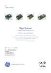
1
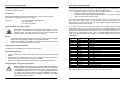
USER MANUAL VersoPlan-II RGB DMX-controlled RGB LED Spot For firmware 50-015-0018-00117-1-00 [MKIII] ENGLISH Page 2-14 RevA 01 5/2013 Order code: 12-015-0113-80500-1-01 User Manual: VersoPlan-II RGB ■ Introduction Congratulations on the purchase of a Multiform-branded item and the trust having been put in us with this decision. Multiform is one of the leading global manufacturers of professional lighting equipment and has decades of experience in design, production and quality assurance. To meet your requirements, this unit has been designed and built to the highest standards, so that we can assure you that you have made a good and satisfying investment. To take full advantage of all possibilities and for your own safety and the safety of your environment, please read these operating instructions carefully before you start using the unit. ■ Product description The VersoPlan-II RGB series are high-power, color mixing, solid state lighting fixtures with a broad range of possible applications from show lighting to architectural installations. SAFETY INFORMATION Read the safety precautions in this chapter before installing, powering up, operating or servicing this device. Failure to do so may void the product warranty, and releases the manufacturer from all product liability. ■ Symbols used in this manual The following symbols are used to identify important safety information on the product and in this manual: WARNING! Read manual before installation, operation or servicing. WARNING! Safety hazard. Risk of injury or death. WARNING! Hazardous voltage. Risk of severe or fatal electric shock. WARNING! Shock hazard. Equipment must be properly grounded. WARNING! Hot surface. Risk of skin burn or skin irritation. V1.00 (02-2012) 2 User Manual: VersoPlan-II RGB User Manual: VersoPlan-II RGB ■ Maintenance WARNING! Fire hazard. This device does not need regular maintenance. It is protected by an internal fuse located on the power supply PCB. If this fuse fails, this usually indicates an internal fault requiring servicing by a qualified engineer. The fuse shall only be replaced by a fuse of same specification, and the replacement has to be made by qualified personnel obeying applicable safety rules. WARNING! Laser radiation. Risk of surface damage. WARNING! LED light emission. Risk of eye injury. ■ Technical data VERSOPLAN-II RGB Mains Input…………………………………………………………….AC100-250V~ 50/60Hz Power supply type………………………………………………………….……..switch mode Fuse…………………………………………………….……….internal (see service manual) DMX connections…………………………………………………3 pin XLR (Male / Female) Modulation Type…………………….……..…..………….Pulse Density Modulation (PDM) Control protocol.......................................................................................DMX 512 (1990) ■ Security advice before use General advice: 1. Read this manual completely before using the product. 2. Keep this manual in your records for future reference. 3. Follow all instruction printed in this manual. 4. Follow all printed security advice on the product itself. 5. Take care of enough distance between this product and sources of hum and noise like electric motors and transformers. 6. Carry this product with greatest care. Punches, big forces and heavy vibration may damage this product mechanically. Version data LEDs Dispersion Power Consumption Dimension WxHxD (w/o bracket) Weight VersoPlan-HT3018 18x3W (3x350mA) 18 RGB (TriLED) 25° Max. 65W 210.0×210.0x 73.0mm 3.10 kg VersoPlan-HT3030 30x3W (3x350mA) 30 RGB (TriLED) 25° Max. 95W 319.0×210.0×73.0mm 4.60 kg Protection from eye injury 1. Warning: Depending on the configuration of the device, this device may reach or exceed the limits of EN62471, risk group 2, and may hence reach to risk group 3. 2. To avoid eye injury, do not look into the beam from a distance of less than 8.5 m (27 ft. 11 ins) from the front surface of the fixture without protective eyewear such as shade-5 welding goggles. At larger distances, light output is harmless to the naked eye provided that the eye’s natural aversion response is not affected. 3. Do not view the beam directly with optical instruments such as magnifiers, telescopes, binoculars or similar optical instruments that may concentrate the light output. 4. Ensure that during setup and DMX programming, no persons are inside a 8.50m (27 ft. 11 ins) vicinity of the device’s front surface, to avoid that they may accidently be exposed to the light beam. ■ Standards This product complies with the following standards: EU electrical safety................................................EN60598-1:2008, EN60598-2-1:1989 EU photobiological safety.........................................................................EN 62471:2008 EU EMC......................................EN55015: 2006 + A1:2007, EN61547:1995 + A1:2000 EU Harmonics ...................................................................................EN61000-3-2:2006 EU Flicker …………………...…………………………………………….EN61000-3-3:2008 US safety ………….…………..………………………………………………………UL60065 US EMC………………………..…………………………………………………..FCC Part 15 Protection from electric shock: 1. Only connect this unit to a mains socket outlet with protective earth connection, ground-fault (earth-fault) and overload protection. 2. Where the mains plug or an appliance coupler is used as a disconnect device, such device shall remain readily operable. 3. To pull the AC Cord out of the wall outlet or the unit’s AC socket, never pull the cable itself, but only the AC plug. 4. Disconnect the unit from AC supply before any kind of cleaning on This product meets both the EMC Directive 2004/108/EC and the Low Voltage Directive 2006/95/EC. V1.00 (02-2012) 14 V1.00 (02-2012) 3 User Manual: VersoPlan-II RGB 5. 6. 7. 8. User Manual: VersoPlan-II RGB the product. Use smooth and dry cloth only for cleaning. Do not expose this unit to any dripping or splashing liquids, and do not place objects filled with liquids, such as vases, on the unit. Do not operate this unit near to open water or in high humidity. Choose the position of the AC cord according to the lowest risk of damage by foot steps or by squeezing it. Do not open the unit for service, there are no user-serviceable parts inside. Warranty will be void in any case of unauthorized service by the user or other not authorized persons. Protection from fire: 1. Take care of not placing the unit near sources of heat (e.g. powerful amplifiers, fog machines). 2. Allow at least about 0.15m (6 ins.) between this unit and other devices or a wall to allow for proper cooling. 3. Take always care of sufficient air convection in the unit’s environment to avoid overheating. Make sure air convection slots are not blocked. Do not operate this unit in environmental temperatures exceeding 35 degrees Celsius. 4. Be sure this fixture is kept at least 0.75m (30ins.) away from any flammable materials (decoration etc.). 5. Do not stick filters, masks or other materials directly on the LEDs or the LED cover screen. 6. Check the total maximum power of your AC wall outlet if you connect several units to one wall outlet and avoid any overloading. 7. If the device itself has an AC outlet for providing power to other units, make sure to not exceed the specified maximum load. Protection from injury and damage: 1. Never use any accessories or modifications not authorized by the manufacturer of this unit. 2. Choose a location for operation where the unit is protected from vibration and where a fixed mounting position is provided. In case of overhead-mounting, follow applicable rigging requirements. 3. Before plugging the AC cord in the wall outlet, check whether the AC plug, the mains voltage and frequency are the same as this product is specified for. If not, contact you dealer immediately. 4. The surface of the device may get hot during operation, and heat sink areas may reach to or exceed the limits of EN60950. Do not touch heat sink areas of the device during operation, and allow 20 minutes of cool-down time after powering off before touching. 5. If fluids have spilled into the unit or small parts have intruded the unit, immediately switch off the unit and hand it over to the authorized service for a security check. 6. Disconnect the unit from AC supply by pulling the AC plug out of the wall outlet or the unit’s AC socket during a thunder-storm in V1.00 (02-2012) 4 operation in “d5” (DMX 5-channel) mode. Shortly after that, the display shows the DMX starting address. You can choose any DMX starting address by simply using the UP/DOWN buttons on the unit itself. The chosen DMX-address comes effective approximately 3 seconds later and will show up on the display on the unit itself in alternation to the “d”. This allows control of the unit by any external DMX signal sending on the chosen channels. Once such signal is received, a LED on the lower right side of the “d” in the display indicates that a DMX signal is present. The unit receives DMX values on a packet of 5 consecutive DMX channels, with the following functional assignment: CH1 = 000…255 Dimmer RED CH2 = 000…255 Dimmer GREEN CH3 = 000...255 Dimmer BLUE CH4 = 000…255 Master Dimmer 0…100% CH5 = 000…049 Strobe off, 050…255 Strobe rate (050=slow / 255=max. speed 23 Hz) “dP” Mode (DMX Preset Mode) Press the MODE button on the unit itself until the display shows “dP”, indicating operation in “dP” (DMX Preset) mode. Shortly after that, the display shows the DMX starting address. You can choose any DMX starting address by simply using the UP/DOWN buttons on the unit itself. The chosen DMX-address comes effective approximately 3 seconds later and will show up on the display on the unit itself in alternation to the “d”. This allows control of the unit by any external DMX signal sending on the chosen channels. Once such signal is received, a LED on the lower right side of the “d” in the display indicates that a DMX signal is present. The unit receives DMX values on a packet of 4 consecutive DMX channels, with the following functional assignment: CH1 = Choice of fixed colors (if CH3 < 25) or fade/switch pattern presets (if CH ≥ 25) CH2 = 000…255 Master Dimmer 0…100% CH3 = Function choice C (Color – static) and A (Auto) mode, speed setting for A mode. CH3 0……24 selects the fixed color (C) mode. Color choice by CH1. CH3 25.....234 selects the auto (A) mode and determines the speed. Pattern choice by CH1. CH3 235…255 selects the sound-to-light (S) mode. Pattern choice by CH1. CH4 = 000…049 Strobe off, 050…255 Strobe rate (050=slow / 255=max. speed 23 Hz) Display on/off The display of the unit will turn off after 25 seconds of not receiving any user commands through the user interface buttons. On the first hit of any button, the display will light up again; this first hit will not change any settings, only when you press any button after that, settings will be affected. V1.00 (02-2012) 13 User Manual: VersoPlan-II RGB User Manual: VersoPlan-II RGB “d3” Mode (DMX 3CH Mode) 7. Press the MODE button on the unit itself until the display shows “d3”, indicating operation in “d3” (DMX 3-channel) mode. Shortly after that, the display shows the DMX starting address. You can choose any DMX starting address by simply using the UP/DOWN buttons on the unit itself. The chosen DMX-address comes effective approximately 3 seconds later and will show up on the display on the unit itself in alternation to the “d”. This allows control of the unit by any external DMX signal sending on the chosen channels. Once such signal is received, a LED on the lower right side of the “d” in the display indicates that a DMX signal is present. The unit receives DMX values on a packet of 3 consecutive DMX channels, with the following functional assignment: CH1 = 000…255 Dimmer RED CH2 = 000…255 Dimmer GREEN CH3 = 000....255 Dimmer BLUE Note: If you wish to operate a unit as a “slave” to another unit which is operating in a stand-alone mode (like COLOR, AUTO or SOUND mode), then you must choose the d3 mode and set the starting address to 001. “d4” Mode (DMX 4CH Mode) Press the MODE button on the unit itself until the display shows “d4”, indicating operation in “d4” (DMX 4-channel) mode. Shortly after that, the display shows the DMX starting address. You can choose any DMX starting address by simply using the UP/DOWN buttons on the unit itself. The chosen DMX-address comes effective approximately 3 seconds later and will show up on the display on the unit itself in alternation to the “d”. This allows control of the unit by any external DMX signal sending on the chosen channels. Once such signal is received, a LED on the lower right side of the “d” in the display indicates that a DMX signal is present. The unit receives DMX values on a packet of 4 consecutive DMX channels, with the following functional assignment: ■ Health advice This unit produces and absorbs electromagnetic radiation. The strength of radiation and the sensitivity for disturbing interference matches the CE and FCC requirements. A corresponding sign is printed on the backside of the unit. Any change or modification may affect the behavior of the unit concerning electromagnetic radiation, with the CE requirements eventually not to be met any more. The manufacturer takes no responsibility in this case. ■ Functional advice This unit is immune to the presence of electromagnetic disturbances – both conducted and radiated - up to a certain level. Under peak conditions, the unit is classified to show a “class C” performance criteria and may encounter temporary degradation or loss of function which may need manual help to recover. In such case, disconnect the AC power from the unit and reconnect it again to recover. ■ Environmental advice This unit is built to conform to the ROHS standards and the WEEE directive 2002/96/EC of the European Parliament and of the Council of the European Union. Under these regulations, the product shall not be discarded into regular garbage at the end of its life, but shall be returned to authorized recycling stations. ■ LED Lifetime advice CH1 = 000…255 Dimmer RED CH2 = 000…255 Dimmer GREEN CH3 = 000...255 Dimmer BLUE CH4 = 000…127 Master Dimmer 0…100% CH4 = 128…227 Strobe speed (128=slow / 227=max. speed 23 Hz) CH4 = 228…255 Master Dimmer = 100% Strobe off “d5” Mode (DMX 5CH Mode) Press the MODE button on the unit itself until the display shows “d5”, indicating V1.00 (02-2012) 8. order to avoid any damage on the unit due to AC voltage peaks. In cause of not correct function of this unit or damaged AC cord or other damaged parts, pull immediately the AC plug out of the wall outlet and hand the unit over to the authorized service for a security check. To meet all aspects of functionality and security during maintenance work to be preformed on this unit, all parts should be replaced by genuine spare parts. Consequently, take care of your dealer or maintenance company to be authorized by the manufacturer. 12 LED lifetime is determined by the gradually declining brightness of a LED over time, with a point of 50% brightness reduction marking the defined end of its lifetime. The driving factor of this effect is the heat that the chip inside the LED is exposed to. While a chip may under ideal circumstances reach to more than 100000 hours of lifetime, the real-world lifetime may only be 30000 to 50000 hours or less if the LED is exposed to excessive heat, which can be caused by continuously running all LEDs inside this device at full power and operating the unit in high environmental temperatures. If improving the lifespan expectancy is a priority, take care of providing for lower V1.00 (02-2012) 5 User Manual: VersoPlan-II RGB User Manual: VersoPlan-II RGB operational temperatures. This may include forced external cooling and/or the reduction of overall projection intensity. In S (Sound-to-Light) mode, the speed of the pattern progress is determined by the signal picked up by the internal microphone. Every detected beat will Temporarily speed up the color fade in pattern presets 0….9, creating a “pulsating” effect in synchronization with the music. Switch to the next pattern step in pattern presets 10….19, creating a “chasing” effect in synchronization with the music. ■ Unpacking Please check that the box contains the following items, and contact your dealer immediately for replacement if any part is missing: Main parts: The output level (brightness) can be set in 10 levels: 10% | 20% | 30% | 40% | 50% | 60% | 70% | 80% | 90% | 100%. To do this with the on-board user interface, the user must change into COLOR mode first and make a global brightness adjustments as described in the COLOR mode chapter 1 pc. VERSOPLAN-II RGB main unit 1 pc. mains cable 1 pc. operation manual ■ Getting started: choosing a location Risk of fire: The VERSOPLAN-II RGB has been designed to work in dry indoor environments at environmental temperatures up to 35 degrees Celsius. For proper operation, the unit must be operated with unobstructed air convection to its outside metal case. Do not: Operate the VERSOPLAN-II RGB in environments with more than 35 degrees environmental temperature or more than 75% relative humidity. Operate the VERSOPLAN-II RGB in any closed environment smaller than 10cbm, unless forced air convection is provided. ■ Getting started: secure mounting The VERSOPLAN-II RGB can be mounted in various ways: Floor standing operation Turn the bracket to the lower side of the unit and fold out the second, inlaying bracket. Place the unit in a secure position where it can neither be touched by anyone or could possibly become an objective for anyone to stumble. Make sure to comply with cooling requirements of the used power supply if any. Hanging/Rigging, ceiling-mounted operation Risk of injury: Overhead mounting requires extensive experience, including among others calculating working load limits, good knowledge of the installation material being used, and periodic safety inspection of all installation material and the unit. If you lack such qualifications, do not attempt the installation yourself. Improper installation can result in body injury. Be sure to complete all rigging and installation procedures before applying power to the unit. V1.00 (02-2012) 6 In “S” mode, the unit does not receive any values from the DMX input but generates related DMX values on the output (3CH) according to the selected pattern, so that further units can show the same behaviour if they are connected by DMX signal cables and set to d3 Mode with selected start address = 001. If you leave mode “SLx” for any reason and come back later into mode “SLx”, the unit will recall the last chosen preset (even if the unit was switched off in between). Available pattern presets (transition is “switching”): Preset S0 S1 S2 S3 S4 S5 S6 S7 S8 S9 S10 S11 S12 S13 S14 S15 S16 S17 S18 S19 Transition Fading Fading Fading Fading Fading Fading Fading Fading Fading Fading Switching Switching Switching Switching Switching Switching Switching Switching Switching Switching Color sequence Red, Green Green, Blue Red, Blue Red, Yellow Orange-Frog Pink-Blue Turquoise-Pink Red, green, blue Yellow, turquoise, pink Red, green, orange, turquoise, blue, pink Red, Green Green, Blue Red, Blue Red, Yellow Orange-Frog Pink-Blue Turquoise-Pink Red, green, blue Yellow, turquoise, pink Red, green, orange, turquoise, blue, pink Note: patterns Sx0-Sx9 are identical to the patterns used in Axx mode. V1.00 (02-2012) 11 User Manual: VersoPlan-II RGB User Manual: VersoPlan-II RGB “A” Auto Mode Press the MODE button on the unit itself until the display shows “Axx”, indicating operation in “A” mode with chosen pattern “xx”; then choose by using the UP/DOWN buttons one of the 24 pattern presets as shown in the list below. The speed of the pattern progress can be set in 10 levels: 3 BPM (0.05Hz) | 6 BPM (0.1Hz) | 30 BPM (0.5Hz) | 60 BPM (1.0Hz) | 90 BPM (1.5Hz) | 120 BPM (2.0Hz) | 150 BPM (2.5 Hz) | 200 BPM (3.2Hz) | 320 BPM (5.2Hz) | 480 BPM (8.0Hz). This is done by pressing and holding the MODE button and then pressing the UP or DOWN buttons to change the speed. Note that the speed setting using the on-board user interface can only be done in AUTO mode. The output level (brightness) can be set in 10 levels: 10% | 20% | 30% | 40% | 50% | 60% | 70% | 80% | 90% | 100%. To do this with the on-board user interface, the user must change into COLOR mode first and make a global brightness adjustment as described in the COLOR mode chapter. In “Axx” mode, the unit does not receive any values from the DMX input but generates related DMX values on the output (3CH) according to the selected pattern, so that further units can show the same behaviour if they are connected by DMX signal cables and set to d3 Mode with selected start address = 001. If you leave mode “Axx” for any reason and come back later into mode “Axx”, the unit will recall the last chosen pattern (even if the unit was switched off in between). Available pattern presets: Fade Transition A00 A01 A02 A03 A04 A05 A06 A07 A08 A09 Red, Green Green, Blue Red, Blue Red, Yellow Orange-Frog Pink-Blue Turquoise-Pink Red, green, blue Yellow, turquoise, pink Red, green, orange, turquoise, blue, pink Switch Transition A10 A11 A12 A13 A14 A15 A16 A17 A18 Red, Green Green, Blue Red, Blue Red, Yellow Orange-Frog Pink-Blue Turquoise-Pink Red, green, blue Yellow, turquoise, pink A19 Red, green, orange, turquoise, blue, pink Strobe white Strobe red Strobe green Strobe Blue Risk of fire / Safety risk The VERSOPLAN-II RGB requires an AC power source with sufficient power carriage and correct grounding to ensure safe operation. The AC power source must be equipped with a circuit breaker and earth leakage detector. Make sure to only use compliant AC supply lines. The VERSOPLAN-II RGB has an AC outlet that is designed to carry loads of no more than 8A. Make sure that all connected devices in a chain fed by the first device do not exceed a maximum of 8A current consumption. * Note: Patterns Ax0-Ax9 are identical to the patterns used in S mode. ■ Getting started: making DMX control connections “S” Sound-to-Light Mode Press the MODE button on the unit itself until the display shows “Sxx”, indicating operation in “S” mode with chosen pattern “xx”; then choose by using the UP/DOWN buttons one of the 20 pattern presets as shown in the list below. V1.00 (02-2012) ■ Getting started: making AC supply connections Strobes 16Hz A20 A21 A22 A23 Leave the inner and outer bracket folded. The unit should be installed out of reach of people and outside areas where persons may walk by or be seated. Make sure that the installation area can hold a minimum point load of 10 times the device’s weight. In fixed installations, fix the unit with self-locking screws/nuts to the mounting point. When mounting the unit to truss be sure to secure an appropriately rated clamp to the hanging yoke using a M10 screw fitted through the center hole of the hanging yoke. Where required, secure the installation with an appropriate safety cable. Always use a certified safety cable according to EN60598-2-17 Section 17.6.6 that can hold 12 times the weight of the device when installing the unit. This secondary safety attachment should be installed in a way that no part of the installation can drop more than 20cm if the main attachment fails. Never stand directly below the device when mounting, removing, or servicing the fixture. Make sure the area below the installation place is free from unwanted persons during rigging, de-rigging and servicing. The operator has to make sure that the safety-relating and machine-technical installations are approved by an expert before using them for the first time. The installations should be re-inspected every year. Make sure to comply with applicable cooling requirements if any. 10 Connect the VERSOPLAN-II RGB to a suitable DMX controller where needed, and interconnect several units by means of their DMX In/Outputs as required. The last unit shall be equipped with a proper 120 Ohm termination resistor equipped DMX-plug as shown in below drawing. Please make sure that all used DMX cables comply to below standard: V1.00 (02-2012) 7 User Manual: VersoPlan-II RGB User Manual: VersoPlan-II RGB 5 6 7 8 DMX input DMX output AC output AC input Upon the user’s choice, the unit can work in stand-alone automatic mode, or with fixed colors, or it may be controlled by external DMX-controllers. Available modes: “C” Color Mode Press the MODE button until the display shows “Cxx”, indicating operation in “C” mode with chosen preset “xx”, then choose by using the UP/DOWN buttons one of the 13 color presets as shown in the list below. The output level (brightness) can be set in 10 levels: 10% | 20% | 30% | 40% | 50% | 60% | 70% | 80% | 90% | 100%. This is done by pressing and holding the MODE button and then pressing the UP or DOWN buttons to change the brightness. Note that the brightness setting using the on-board user interface can only be done in COLOR mode and is a global setting for all stand-alone modes, which means that the same chosen brightness remains applicable for the AUTO and SOUND modes as well. The brightness chosen on the unit itself however has no influence in any of the DMX modes. ■ Operation In “C” mode, the unit does not receive any values from the DMX input but generates related DMX values on the output (3CH) according to the selected preset, so that further units can show the same behaviour if they are connected by DMX signal cables and set to d3 Mode with selected start address = 001. If you leave mode “C” for any reason and come back later into mode “C”, the unit will recall the last chosen color preset (even if the unit was switched off in between). Available color presets: Preset C 0 C1 C2 C3 C4 C5 C6 C7 C8 C9 C10 C11 C12 C13 User interface overview: 1 2 3 4 MODE selection button UP-Button DOWN-Button Display showing the Mode, DMX-address, etc. V1.00 (02-2012) 8 Colour White (W) Red (R) Green (G) Blue (B) Yellow (Y) Pink (P) Turquoise (T) Lime (L) Orange (O) Marine (M) Frog (F) Lavender (V) Candy (C) Blackout V1.00 (02-2012) R 0 255 0 0 255 255 0 127 255 0 0 127 255 0 G 0 0 255 0 170 0 255 255 85 127 255 0 0 0 B 0 0 0 255 0 255 255 0 0 255 127 255 127 0 9