1
Reference Manual
P VD 5660 D
P VD 5660 B
Dual Channel SD/HD Multi-format Frame Synchronizer with Full
Embedded and External AES Audio Support
Revision 2.6 – November 2010
This Manual Supports Device Revisions:
P VD 5660 Firmware Revision
Control System GUI Release
402
4.8.2
Information in this document is subject to change without notice. No part of this document may be reproduced or
transmitted in any form or by any means, electronic or mechanical for any purpose, without express written permission of
LYNX Technik AG.
LYNX Technik AG may have patents, patent applications, trademarks, copyrights or other intellectual property rights
covering the subject matter in this document. Except as expressly written by LYNX Technik AG, the furnishing of this
document does not give you any license to patents, trademarks, copyrights or other intellectual property of LYNX Technik
AG or any of its affiliates.
LYNX Technik AG
Brunnenweg 3
D 64331 Weiterstadt
Germany
www.lynx-technik.com
© 2008-2010 LYNX Technik AG all rights reserved
P VD 5660 Reference Manual. Rev 2.6
Contents
Contents ................................................................................................................................................ 2
Warranty ................................................................................................................................................ 5
Regulatory information ....................................................................................................................... 6
Europe........................................................................................................................................................ 6
Declaration of Conformity ........................................................................................................................................ 6
USA ............................................................................................................................................................ 6
FCC 47 Part 15 ....................................................................................................................................................... 6
Getting Started ..................................................................................................................................... 7
Packaging .................................................................................................................................................. 7
ESD Warning ............................................................................................................................................. 7
Preventing ESD Damage ........................................................................................................................................ 7
Product Description ............................................................................................................................ 8
Input Video Formats ................................................................................................................................... 9
Output Video Formats ...............................................................................................................................10
Input Reference Signal ..............................................................................................................................11
Reference Lock .........................................................................................................................................12
Frame Synchronization .............................................................................................................................12
ARC (Aspect Ratio Conversion) ................................................................................................................13
Conversion from 16:9 to 4:3 Aspect Ratio ............................................................................................................. 13
Conversion from 4:3 to 16:9 Aspect Ratio ............................................................................................................. 14
ARC Image Size and Positioning........................................................................................................................... 14
Video Processing ......................................................................................................................................15
Proc Amp Functions .............................................................................................................................................. 15
Aperture Correction ............................................................................................................................................... 15
Test Patterns ......................................................................................................................................................... 15
Programmable Video Output Delay ....................................................................................................................... 15
Fixed Processing Delays ....................................................................................................................................... 16
Audio Processing ......................................................................................................................................18
Pathway 1 ............................................................................................................................................................. 18
Pathway 2 ............................................................................................................................................................. 18
Pathway 3 – (For DolbyE) ..................................................................................................................................... 18
Pathway 4 and Pathway 5 ..................................................................................................................................... 18
Automatic Audio Detection .................................................................................................................................... 19
Configuring Audio Inputs ....................................................................................................................................... 20
Maintaining DolbyE Transparency ......................................................................................................................... 21
Automatic Audio Synchronization & Channel Assignment (ASCA) ........................................................................ 23
Introduction ...................................................................................................................................................... 23
Working Principle ............................................................................................................................................. 24
Limited Sync Resources .................................................................................................................................. 24
Limitations:....................................................................................................................................................... 25
GPI Function .............................................................................................................................................27
Switch Inputs......................................................................................................................................................... 27
Freeze input with GPI ............................................................................................................................................ 28
User Presets – GPI Switch .................................................................................................................................... 28
Functional Diagram ...................................................................................................................................28
Connections ....................................................................................................................................... 31
Video .........................................................................................................................................................31
External Audio (AES) ................................................................................................................................31
Installation .......................................................................................................................................... 32
Firmware Options .............................................................................................................................. 33
Second Input Option (OC-5660-SCND) ....................................................................................................33
Down Conversion Option (OC-5660-DWN) ...............................................................................................34
Up/Down/Cross Conv. Option (OC-5660-UPXD) ......................................................................................35
Down conversion................................................................................................................................................... 35
Up Conversion ...................................................................................................................................................... 35
Cross Conversion.................................................................................................................................................. 36
Page 2 of 79
P VD 5660 Reference Manual. Rev 2.6
Image size and Positioning.................................................................................................................................... 36
Color Space Conversion ....................................................................................................................................... 36
Noise Reduction (optional: OC-5660-NR) .................................................................................................37
General Noise Reduction ...................................................................................................................................... 37
Block Artifact Reduction ........................................................................................................................................ 37
Mosquito Noise Reduction..................................................................................................................................... 37
Detail Enhancement (Sharpness and Texture) ...................................................................................................... 37
Settings and Control ......................................................................................................................... 38
Multi Function Switch ................................................................................................................................38
Using the Local Display Menus .................................................................................................................38
Menu Structure..........................................................................................................................................39
LED Status Indicators ....................................................................................................................... 40
SDI 1 Status LED 1 ...................................................................................................................................40
SDI 2 Status LED 2 ...................................................................................................................................40
Ref Status LED 3 ......................................................................................................................................40
ALARM LED ..............................................................................................................................................40
Control System GUI ........................................................................................................................... 41
Main Tab ...................................................................................................................................................42
REF in Select ........................................................................................................................................................ 42
Signal Routing....................................................................................................................................................... 42
Video Proc Tab .........................................................................................................................................43
General Video Settings ......................................................................................................................................... 43
Frequency Pre-select ............................................................................................................................................ 43
Freeze Mode ......................................................................................................................................................... 44
Synchronization Mode ........................................................................................................................................... 45
Synchronous SDI Input (minimum audio delay) ..................................................................................................... 46
DVITC Input Line Selection ................................................................................................................................... 46
Conv1 / Conv2 Tab ...................................................................................................................................47
Converter Source .................................................................................................................................................. 47
Control Mode ........................................................................................................................................................ 47
Input Aspect Ratio ................................................................................................................................................. 48
Down Converter Mode .......................................................................................................................................... 48
Output Format ....................................................................................................................................................... 48
Inserted Format Description .................................................................................................................................. 48
SDTV Aspect Ratio Converter Mode ..................................................................................................................... 48
Advanced Metadata Settings ................................................................................................................................. 49
Closed Captions: ................................................................................................................................................... 49
Time Code: ........................................................................................................................................................... 50
Detected Time Code: ............................................................................................................................................ 51
Time Code Insertion: ............................................................................................................................................. 51
Teletext .....................................................................................................................................................53
Teletext Decoder ................................................................................................................................................... 53
HQ Scaler Tab ..........................................................................................................................................56
HQ Scaler Source ................................................................................................................................................. 56
Control Mode ........................................................................................................................................................ 56
Input Aspect Ratio ................................................................................................................................................. 57
Output Format ....................................................................................................................................................... 57
Inserted Format Description .................................................................................................................................. 57
Conversion Mode .................................................................................................................................................. 57
Input Cropping....................................................................................................................................................... 57
Output Cropping .................................................................................................................................................... 57
Noise Reduction Tab .................................................................................................................................58
General Noise Reduction ...................................................................................................................................... 58
Block Artifact Reduction ........................................................................................................................................ 58
Mosquito Noise Reduction..................................................................................................................................... 58
Detail Enhancement (Sharpness and Texture) ...................................................................................................... 58
Output Proc Tabs ......................................................................................................................................59
Color Space Conversion ....................................................................................................................................... 59
Aperture Correction ............................................................................................................................................... 60
Clip CR/Cb Headroom ........................................................................................................................................... 60
H and V Blanking .................................................................................................................................................. 60
Video Output Delay Adjustment............................................................................................................................. 60
Settings ................................................................................................................................................................. 60
Output if no input.............................................................................................................................................. 60
Page 3 of 79
P VD 5660 Reference Manual. Rev 2.6
Freeze Mode.................................................................................................................................................... 61
Test Pattern Pre-select .................................................................................................................................... 61
Test Pattern Standard ...................................................................................................................................... 61
Test Pattern Enable ......................................................................................................................................... 61
Video Adjustments ........................................................................................................................................... 61
Timing Tab ................................................................................................................................................62
Audio Delay Pulse ................................................................................................................................................. 63
AES Input Crossbar Tab ...........................................................................................................................64
Automatic Audio Detection .................................................................................................................................... 64
Configuring Audio Inputs ....................................................................................................................................... 65
Maintaining DolbyE Transparency ......................................................................................................................... 66
Pathway 1 ........................................................................................................................................................ 67
Pathway 2 ........................................................................................................................................................ 67
Pathway 3 – Dolby E ........................................................................................................................................ 67
Pathway 4 and 5 .............................................................................................................................................. 68
AES Proc Tab ...........................................................................................................................................69
AES Out Tab .............................................................................................................................................70
Setting Mono Cross Points .................................................................................................................................... 70
Output Mux Tabs .......................................................................................................................................72
User Presets Tab ......................................................................................................................................73
To save a preset ................................................................................................................................................... 73
To load a saved preset .......................................................................................................................................... 73
Setting GPI control of Preset selections ................................................................................................................ 74
GPI Influence ........................................................................................................................................................ 74
Options Tab...............................................................................................................................................75
Events Tab ................................................................................................................................................76
Log in GUI Function .............................................................................................................................................. 76
Alarm Activation .................................................................................................................................................... 76
SNMP Support ...................................................................................................................................................... 76
Specifications ..................................................................................................................................... 77
Service ................................................................................................................................................. 79
Parts List ...................................................................................................................................................79
Technical Support .....................................................................................................................................79
Contact Information .......................................................................................................................... 79
Page 4 of 79
P VD 5660 Reference Manual. Rev 2.6
Warranty
LYNX Technik AG warrants that the product will be free from defects in materials
and workmanship for a period of two (2) year from the date of shipment. If this
product proves defective during the warranty period, LYNX Technik AG at its
option will either repair the defective product without charge for parts and labor,
or will provide a replacement in exchange for the defective product.
In order to obtain service under this warranty, customer must notify LYNX
Technik of the defect before expiration of the warranty period and make suitable
arrangements for the performance of service. Customer shall be responsible for
packaging and shipping the defective product to the service center designated by
LYNX Technik, with shipping charges prepaid. LYNX Technik shall pay for the
return of the product to the customer if the shipment is within the country which
the LYNX Technik service center is located. Customer shall be responsible for
payment of all shipping charges, duties, taxes and any other charges for
products returned to any other locations.
This warranty shall not apply to any defect, failure, or damage caused by
improper use or improper or inadequate maintenance and care. LYNX Technik
shall not be obligated to furnish service under this warranty a) to repair damage
resulting from attempts by personnel other than LYNX Technik representatives to
install, repair or service the product; b) to repair damage resulting from improper
use or connection to incompatible equipment; c) to repair any damage or
malfunction caused by the use of non LYNX Technik supplies; or d) to service a
product which has been modified or integrated with other products when the
effect of such modification or integration increases the time or difficulty servicing
the product.
THIS WARRANTY IS GIVEN BY LYNX TECHNIK WITH RESPECT TO THIS
PRODUCT IN LIEU OF ANY OTHER WARRANTIES, EXPRESS OR IMPLIED.
LYNX TECHNIK AND ITS VENDORS DISCLAIM ANY IMPLIED WARRANTIES
OF MERCHANTABILITY OR FITNESS FOR A PARTICULAR PURPOSE. LYNX
TECHNIK`S RESPONISIBILITY TO REPAIR AND REPLACE DEFECTIVE
PRODUCTS IS THE SOLE AND EXCLUSIVE REMEDY PROVIDED TO THE
CUSTOMER FOR BREACH OF THIS WARRANTY. LYNX TECHNIK AND ITS
VENDORS WILL NOT BE LIABLE FOR ANY INDIRECT, SPECIAL,
INCIDENTIAL, OR CONSEQUENTIAL DAMAGES IRRESPECTIVE OF
WHETHER LYNX TECHNIK OR THE VENDOR HAS ADVANCE NOTICE OF
THE POSSIBILITY OF SUCH DAMAGES.
Page 5 of 79
P VD 5660 Reference Manual. Rev 2.6
Regulatory information
Europe
Declaration of Conformity
LYNX Technik AG
Brunnenweg 3
D-64331 Weiterstadt
Germany
Declare under our sole responsibility that the product
We
TYPE: P VD 5660 B, P VD 5660 D
To which this declaration relates is in conformity with the following
standards (environments E1-E3):
EN 55103-1 /1996
EN 55103-2 /1996
EN 60950 /2001
Following the provisions of 89/336/EEC and 73/23/EEC directives.
Winfried Deckelmann
Weiterstadt, August 2008
Place and date of issue
Legal Signature
USA
FCC 47 Part 15
This device complies with part 15 of the FCC Rules. Operation is subject to the following
two conditions: (1) This device may not cause harmful interference, and (2) this device
must accept any interference received, including interference that may cause undesired
operation.
Note: This equipment has been tested and found to comply with the limits for a Class A
digital device, pursuant to the part 15 of the FCC Rules. These limits are designed to
provide reasonable protection against harmful interference when the equipment is
operated in a commercial environment. This equipment generates, uses, and can radiate
radio frequency energy and, if not installed and used in accordance with the instruction
manual, may cause harmful interference to radio communications. Operation of this
equipment in a residential area is likely to cause harmful interference in which case the
user will be required to correct the interference at his own expense.
Page 6 of 79
P VD 5660 Reference Manual. Rev 2.6
Getting Started
Most CardModules are installed into the rack frames and system tested in the factory. If
this is an upgrade part or service exchange item then the module is supplied in a padded
cardboard carton which includes the CardModule, rear connection plate and mounting
screws.
Packaging
The shipping carton and packaging materials provide protection for the module during
transit. Please retain the shipping cartons in case subsequent shipping of the product
becomes necessary. Do not remove the module from its protective static bag unless
observing adequate ESD precautions. Please see below.
ESD Warning
This product is static sensitive. Please use caution and use preventative measures to
prevent static discharge or damage could result to module.
Preventing ESD Damage
Electrostatic discharge (ESD) damage occurs when electronic assemblies or the
components are improperly handled and can result in complete or intermittent failure.
Do not handle the module unless using an ESD-preventative wrist strap and ensure that
it makes good skin contact. Connect the strap to any solid grounding source such as any
exposed metal on the rack chassis or any other unpainted metal surface.
Caution
Periodically check the resistance value of the antistatic strap. The measurement should
be between 1 and 10 Megohms.
Page 7 of 79
P VD 5660 Reference Manual. Rev 2.6
Product Description
The P VD 5660 FLEXCARD is a high performance dual channel SD/HD frame
synchronizer / line synchronizer with full embedded and external AES audio support.
Basic functionality is a single channel multi format frame synchronizer and SDTV ARC.
The module provides support for AFD (Active Format Description), WSS (Wide Screen
Signaling) and VI (Video Index) for automated control of the optional converter stages.
Transparency resp. conversion of embedded Metadata is also ensured, including Time
Code and Closed Caption.
Dolby E processing is included in the audio processing stages, i.e. encoded Dolby E
streams are synchronized to the Reference Signal and the Guard Band is automatically
aligned.
Firmware options provide the ability to easily add additional functionality which include:
•
•
•
•
Second Input (option code OC-5660-SCND)
2 Channels of Basic Down Conversion (option code OC-5660-DWN)
Single channel of HQ UP/DOWN/CROSS conversion (option code OC-5660-UPXD)
Single channel of HQ Noise Reduction (option code OC-5660-NR)
Firmware options can be added at any time with a license code. No hardware or
Firmware modifications are required.
Page 8 of 79
P VD 5660 Reference Manual. Rev 2.6
Input Video Formats
The module has two multi-format serial digital inputs (second input is optional) with
automatic input detection. The module will detect the following input standards and
configure the input stage automatically for operation in the connected format.
SDTV Formats
525 / 59.94Hz
625 / 50Hz
HDTV Formats
1080i / 50Hz
1080i / 59.94Hz
1080i / 60Hz
1080p / 23.98Hz
1080p / 24Hz
1080p / 25Hz
1080p / 29.97Hz
1080p / 30Hz
1080psf / 23.98Hz
1080psf / 24Hz
1080psf / 25Hz
720p / 23.98Hz
720p / 24Hz
720p / 25Hz
720p / 29.97Hz
720p / 30Hz
720p / 50Hz
720p / 59.94Hz
720p / 60Hz
Note. As the synchronizer uses a single studio reference input both input signals should
be the same input frequency (frame rate) as the reference for normal operation. (Formats
can be different but the frame rate must match; for example:
Input 1 = 1080i/59.94Hz and Input 2 = 525 59.94Hz with a 59.94Hz reference is valid.
Input 1 = 1080i/59.94Hz and Input 2 = 720P/50Hz with a 59.94Hz reference is not valid
and input 2 will have a disturbed or corrupted output signal.
Page 9 of 79
P VD 5660 Reference Manual. Rev 2.6
Output Video Formats
The module provides eight SDI outputs, user assignable in four sets of two outputs; these
sets can be mapped independently to any of the two input channels. Supported output
video formats are:
SDTV Formats
525 / 59.94Hz
625 / 50Hz
HDTV Formats
1080i / 50Hz
1080i / 59.94Hz
1080i / 60Hz
1080p / 23.98Hz
1080p / 24Hz
1080p / 25Hz
1080p / 29.97Hz
1080p / 30Hz
1080psf / 23.98Hz
1080psf / 24Hz
1080psf / 25Hz
720p / 23.98Hz
720p / 24Hz
720p / 25Hz
720p / 29.97Hz
720p / 30Hz
720p / 50Hz
720p / 59.94Hz
720p / 60Hz
The output format frequency (or frame rate) is determined by the connected reference
signal and the output will remain fixed to this reference regardless of the connected input
signals.
For input signals mismatched to the connected reference frame rate, the synchronizer will
show this as an asynchronous source (indicated by a yellow status indication in the GUI)
and any output signal derived from this “async” source can show video disturbances (see
below “Reference Lock”)
NOTE: For down conversion or HQ up / down / cross conversion additional firmware
options are required. Without these options installed the frame synchronizer passes the
video in the connected input format. (SDTV Aspect Ratio Conversion functionality is
included as part of the basic module).
Page 10 of 79
P VD 5660 Reference Manual. Rev 2.6
Input Reference Signal
The module has a very flexible input reference stage which facilitates the use of either
SDTV analog bi-phase sync (i.e. black burst) or HDTV analog tri-level sync. The
reference input is “cross lock” compatible so an SDTV reference can be used to
frequency lock HDTV signals (and vice versa). The connected reference is auto detected
and the synchronizer automatically configures the outputs to the frame rate of the
connected reference signal.
Supported reference signals are shown below.
SDTV Analog Bi-Level Sync
525 / 59.94Hz
625 / 50Hz
HDTV Analog Tri-Level Sync
1080i / 50Hz
1080i / 59.94Hz
1080i / 60Hz
1080p / 23.98Hz
1080p / 24Hz
1080p / 25Hz
1080p / 29.97Hz
1080p / 30Hz
1080psf / 23.98Hz
1080psf / 24Hz
1080psf / 25Hz
720p / 23.98Hz
720p / 24Hz
720p / 25Hz
720p / 29.97Hz
720p / 30Hz
720p / 50Hz
720p / 59.94Hz
720p / 60Hz
Page 11 of 79
P VD 5660 Reference Manual. Rev 2.6
Reference Lock
If the input frame rate, the output frame rate and the frame rate of the reference signal
are equal, exactly half of each other or double of each other then all modes of the
P VD 5660 operate with no limitations:
•
All 25 Hz and 50 Hz input formats will be synchronized to any 25 Hz or
50 Hz reference signal (from the tables above). The output frame rate
can be any format with a frame rate of 25 Hz or 50 Hz.
•
All 30 Hz and 60 Hz input formats will be synchronized to any 30 Hz or
60 Hz reference signal (from the tables above). The output frame rate
can be any format with a frame rate of 30 Hz or 60 Hz.
•
All 29.97 Hz and 59.94 Hz input format will be synchronized to any 29.97
Hz or 59.94 Hz reference signal (from the tables above). The output
frame rate can be any format with a frame rate of 29.97 Hz or 59.94 Hz.
•
All 23.98 Hz input formats will be synchronized to any 23.98 Hz
reference signal (from the tables above). The output frame rate can be
any format with a frame rate of 23.98 Hz.
•
All 24 Hz input formats will be synchronized to any 24 Hz reference
signal (from the tables above). The output frame rate can be any format
with a frame rate of 24 Hz.
NOTE: If the frame rate of the reference signal is not equal, double or half of the
input/output frame rate, then all functions still are available except the video delay as the
frame rate of the output video does not match the frame rate of the reference signal.
The video output remains frequency locked to the Reference signal.
In this case a synchronized Dolby E signal will not match the required guard band of the
video output signal.
NOTE: If the input frame rate, the output frame rate and the frame rate of the reference
signal do not match then the module’s converters (if activated) will perform a rudimentary
frame rate conversion with drop and repeat frames. This mode of operation is not a
recommended or specified functionality for the P VD 5660, and unwanted artifacts may
occur.
Frame Synchronization
Two independent frame synchronizers are provided, one for each input channel. (Second
input is optional). The algorithms used are extremely robust and very tolerant of poor
input signals. The Synchronizers use “Flywheel” functionality. This allows the module to
recover from any missing sync pulses on the input signal(s) by predicting where they
should be and then re-inserting them.
If no converters are active, the frame synchronizer passes the video in the connected
input format.
The Synchronizers can also be switched into a Line Synchronizer Mode (see page 45)
Page 12 of 79
P VD 5660 Reference Manual. Rev 2.6
ARC (Aspect Ratio Conversion)
The basic module includes three independent ARCs (Aspect Ratio Converters) which
can be used to convert SDTV signals between 4:3 or 16:9 aspect ratios. Two of the
ARCs are fixed in mode and are basic in operation suited better for fixed monitoring
applications. The third ARC is a high quality image processor which has extended
functionality including manually adjustable image size and position. The three ARCs are
internal resources which can be routed to any input signal and any of the four available
outputs.
Modes supported are as follows:
Conversion from 16:9 to 4:3 Aspect Ratio
Letterbox
This takes the 16:9 aspect ratio of the input signal and fits it horizontally into the 4:3 SD
image area with black bars at the top and bottom of the image.
Center Cut
This mode cuts the center portion of the 16:9 input signal and fills the 4:3 SD image area
Stretch to Fill
This mode takes the 16:9 input signal and distorts (vertically stretches) the image to fit
the available 4:3 SD image area.
Page 13 of 79
P VD 5660 Reference Manual. Rev 2.6
Conversion from 4:3 to 16:9 Aspect Ratio
PillarBox
This takes the 4.3 aspect ratio of the input signal and fits it vertically into the 16:9 SD
image area with black bars at the left and right of the image.
Center Cut
This mode cuts the horizontal center portion of the 4:3 input signal and fills the 16:9 SD
image area (cropping the top and bottom of the image)
Stretch to Fill
This mode takes the 4:3 input signal and distorts (horizontally stretches) the image to fit
the available 16:9 SD image area
ARC Image Size and Positioning
The single high quality ARC provides the ability to manually adjust image position and
size for the conversion process.
A 14:9 conversion setting is also added.
Please refer to the GUI section of this manual for more information of the controls
provided and how to use them.
Note: The converters can by automatically controlled by AFD (Active Format
Description), WSS (Wide Screen Signaling) and VI (Video Index). Please refer to the GUI
section of this manual for more information of the controls provided and how to use them.
Page 14 of 79
P VD 5660 Reference Manual. Rev 2.6
Video Processing
Proc Amp Functions
Each of the four output channels has an associated video processing amp which
provides user adjustable Gain / Saturation / Black Level and Hue using on screen
sliders.
Aperture Correction
An adjustable horizontal aperture corrector is provided for each of the four output
channels. This can be used to add (or remove) image sharpness as required.
Note. When using the down converter the filtering process results in a very slight
loss of high frequency information (which is normal), the aperture corrector can
be used to compensate for this slight loss.
Test Patterns
Each of the four output channels has its own independent test pattern generator which
provides a wide selection of test patterns which can be switched into each output.
The selected test pattern is also available as one of the modes the synchronizer will
switch to when excessive video TRS errors are encountered. Possible synchronizer
actions when the input video errors become excessive are:
•
•
•
•
•
Freeze Field 1
Freeze Field 2
Freeze Frame
Selected Test Pattern
Black
Programmable Video Output Delay
Each of the four SDI outputs has separate programmable video output delay which can
be set (independently) between 0 and 3 frames (max). The adjustment is available in
pixel, line and full frame increments.
Note The Synchronizer (including the OC-5660 DWN, and or OC-5660-UPXD
options, if installed) has fixed frame delays depending on the signal path and
selected function (see below). The 0 > 3 frame user adjustment is additional
delay relative to the fixed delays.
This adjustment will delay the SDI video output relative to the connected reference by the
delay setting specified. (+ fixed delay)
Page 15 of 79
P VD 5660 Reference Manual. Rev 2.6
Fixed Processing Delays
The Synchronizer (including the OC-5660 DWN, and or OC-5660-UPXD options, if
installed) has fixed frame delays depending on the signal path and selected function see below:
If signals are routed through the OC-5660-DWN Converters the delays are as follows:
Input Standard
1080i 50
720P 50
1080p 25
1080i 59.94
720p 59.94
1080p 29.97
625
525
Output Standard
625
625
625
525
525
525
625
525
Delay (ms)
79
59
79
65
65
65
39
32
Delay (Frames - rounded to ½ frame)
2
1.5
2
2
2
2
1
1
If signals are routed through the OC-5660-UPXD up/down/cross Converter the delays are
as follows:
Input Standard
1080i 50
1080i 50
1080i 50
1080i 50
720p 50
720p 50
720p 50
720p 50
1080p 25
1080p 25
1080p 25
1080p 25
1080i 59.94
1080i 59.94
1080i 59.94
1080i 59.94
720p 59.94
720p 59.94
720p 59.94
720p 59.94
1080p 29.97
1080p 29.97
1080p 29.97
1080p 29.97
1080i 60
1080i 60
1080i 60
1080i 60
720p 60
720p 60
720p 60
720p 60
1080p 30
1080p 30
1080p 30
1080p 30
1080p 24
1080p 24
1080p 24
1080psF 24
Output Standard
1080i 50
720p 50
1080p 25
720p 25
1080i 50
720p 50
1080p 25
720p 25
1080i 50
720p 50
1080p 25
720p 25
1080i 59.94
720p 59.94
1080p 29.97
720p 29.97
1080i 59.94
720p 59.94
1080p 29.97
720p 29.97
1080i 59.94
720p 59.94
1080p 29.97
720p 29.97
1080i 60
720p 60
1080p 30
720p 30
1080i 60
720p 60
1080p 30
720p 30
1080i 60
720p 60
1080p 30
720p 30
1080p 24
720p 24
1080psF 24
1080p 24
Delay (ms)
118
78
119
119
58
58
99
79
78
78
119
119
98
65
99
99
65
48
49
82
65
48
99
99
98
65
99
99
65
48
65
82
65
48
99
99
124
124
82
124
Page 16 of 79
Delay (Frames - rounded to ½ frame)
3
4
3
3
1.5
3
5
2
2
4
3
3
3
4
3
3
2
3
1.5
2.5
2
3
3
3
3
4
3
3
2
3
2
2.5
2
3
3
3
3
3
1
3
P VD 5660 Reference Manual. Rev 2.6
1080psF 24
1080psF 24
1080p 23.97
1080p 23.97
1080p 23.97
1080psF 23.97
1080psF 23.97
1080psF 23.97
1080i 50
720p 50
1080p 25
1080i 59.94
720p 59.94
1080p 29.97
625
525
625
625
625
625
525
525
525
525
720p 24
1080psF 24
1080p 23.97
720p 23.97
1080psF 23.97
1080p 23.97
720p 23.97
1080psF 23.97
625
625
625
525
525
525
625
525
1080i 50
720p 50
1080p 25
720p 25
1080i 59.94
720p 59.94
1080p 29.97
720p 29.97
124
123
124
124
103
124
124
123
119
79
99
99
82
82
119
65
78
78
119
119
65
48
65
99
Page 17 of 79
3
1.5
3
3
1
3
3
1.5
3
2
2.5
3
2.5
2.5
3
2
2
4
3
3
2
3
2
3
P VD 5660 Reference Manual. Rev 2.6
Audio Processing
The module will de-embed the complete audio payload from each incoming SDI stream
(4 AES groups = 8 AES = 16 audio channels). Audio is de-embedded from both input SDI
signals passed to an AES audio input matrix along with 4 External AES inputs.
The type of audio (PCM, Dolby E or Audio Data) is detected by the module automatically.
The AES input matrix has 20 selectable input channels. There are 5 separate audio
pathways through the frame synchronizer, each one selected according to the application
and requirements for audio processing.
The audio streams can be individually delayed in various zones (see GUI section).
Pathway 1
This audio pathway is scaled 8 x AES signals wide (16 channel). The audio is fed through
selectable sample rate converters (SRC’s) where the audio is re-sampled, synchronized
and then fed into a full audio processing stage, which includes mono gain adjustment,
mute, phase inversion, silence and overload detection.
PCM Audio using this pathway will be free from any audio interference (“pops and clicks”)
when frames are dropped or repeated by the frame synchronizer.
Note. If an encoded Dolby E audio signal is detected by the module the
associated SRC and the following audio processing will be switched off
automatically. For asynchronous Dolby E streams you should use Audio Pathway
3 which provides Dolby E synchronizers.
Pathway 2
This audio pathway is scaled 8 x AES signals wide (16 channels) and bypasses any
sample rate conversion, therefore any of these channels are DolbyE transparent through
the synchronizer. It is assumed the audio is already synchronous to the connected
reference signal (no audio synchronization is performed by the synchronizer(s) on these
audio channels).
Pathway 3 – (For DolbyE)
The PVD 5660 is transparent to any embedded or external DolbyE bit streams:
a) If the input is synchronous - then any audio pathway can be used,
b) If the input is asynchronous - Pathway 3 provides 4 Dolby E synchronizers,
which synchronizes the Dolby E signal to the reference signal and
automatically aligns the guard-band.
Note: Synchronization and auto guard band alignment only works correctly if the frame
rates of the video input/output matches the reference signal (see above “Reference lock).
Note: The Dolby Synchronizers have to be referenced to one of the video outputs or the
AES audio outputs for correct guard band alignment (see also description in the GUI
section below, page 67)
Pathway 4 and Pathway 5
Each of these two pathways are 4 x AES signals wide (8 channels) and these bypass all
internal audio processing and audio synchronization. These channels are simply deembedded audio maintaining synchronization to the respective incoming SDI stream.
Page 18 of 79
P VD 5660 Reference Manual. Rev 2.6
These channels cannot be re-embedded back into the output SDI signals, but can be
routed to the external AES outputs using the output matrix for external processing.
Pathways 1,2 and 3 are fed into 4 independent mono audio output crossbars which
provide 16 channels of audio to 4 independent output embedders, one for each of the
SDI outputs. There is also a 4 x AES (8 channel) external outputs via an independent
mono crossbar if required.
Note. All external AES connections are isolated through transformer coupling.
Automatic Audio Detection
Audio presence and audio format for the embedded audio on the 2 SDI inputs and the 4 x
external AES inputs is automatically detected and displayed on the module GUI in the
LYNX control system.
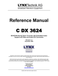
This can be seen below; the small blocks under the de-embedder indicate the audio
status for each AES stream:
P
E
D
= PCM Audio Detected
= Dolby E Audio Detected
= Digital Audio Stream (other than DolbyE) Detected
Blank = No Audio Signal Present
In this example you can see input 2 has no audio present, and input 1 has the following:
AES 1 = PCM Audio
AES 2 = Digital Audio Stream
AES 3 = Dolby E Audio
AES 4 = PCM Audio
AES 5 = PCM audio
AES 6 = PCM Audio
AES 7 = No Audio Present
AES 8 = No Audio Present
Page 19 of 79
P VD 5660 Reference Manual. Rev 2.6
Configuring Audio Inputs
Audio inputs can be configured automatically based on the audio detected, or manually
configured to be only a particular type. When an input is manually configured the system
will indicate when a conflict exists between the configured setting and the detected audio
on that channel by highlighting the box in yellow.
Clicking on one of the audio boxes with the mouse will bring up the audio configuration
dialog for that channel, see below
The default setting is always automatic, as seen above and for this first input you can see
it has detected PCM audio.
To manually set this input simply click on the respective selection with the mouse
In this case you can see input 1 has been manually configured for PCM audio, and it is
highlighted green to indicate it is a manual selection, and there is no conflict. (a box with
a letter inside which is not green indicates this channel is configured for automatic
detection)
Page 20 of 79
P VD 5660 Reference Manual. Rev 2.6
If we manually force this input to DolbyE, this will cause a conflict as PCM audio is
present. See below:
Here you can see the conflict is flagged by turning the box yellow. This is indicating the
channel is manually preset for Dolby E, but the audio format is in conflict with this setting,
in this case PCM audio. Note. Even though there is a conflict the actual audio content is
passed through the system – i.e. it is not blocked.
Maintaining DolbyE Transparency
The PVD 5660 can process and synchronize DolbyE signals transparently, but some
care needs to be taken as to the routing of the DolbyE signals (or any compressed audio
bit stream) through the module. To help maintain transparency the module will
automatically bypass any processing stages which might corrupt this signal, and also
provide a warning indication in the GUI (indicating there is a possible problem with the
specified routing of this signal in the module)
For example, if DolbyE audio is routed through any of the inputs in audio Pathway 1 there
are three areas of concern. b) The sample rate converters, b) the audio processing stage
c) Synchronization and DolbyE guard band timing.
The module will automatically disable the input audio delay, the sample rate converter
and bypass the audio processing for this channel in the Audio Processing amp (controls
will be greyed out) – so in this case the DolbyE signal will be passed transparently and is
ready for re-embedding into the outputs (or passing to an external output). However
audio Pathway 1 does not have any DolbyE synchronization capability, so the DolbyE
audio will not be synchronized and also the guard-band timing could be incorrect. To
indicate this conflict a small warning symbol is inserted into the audio line in the control
system GUI. See below:
Here you can see DolbyE from input 2 has been routed
into audio Pathway 1, channel 2
The module has inserted the warning symbol. Note. The
module has automatically greyed out the sample rate
converter and has also disabled the downstream audio
processing (not seen here)
Page 21 of 79
P VD 5660 Reference Manual. Rev 2.6
A better choice for signal this DolbyE signals is Pathway 3, as this is designed for DolbyE
and includes 4 x DolbyE synchronizers and will always maintain the correct guard-band
timing.
Note: The Dolby Synchronizers have to be referenced to one of the outputs for correct
guard band alignment (see also description in the GUI section below, page 67)
Another area of concern for DolbyE or compressed audio streams is the mono audio
output crossbars. These should not be changed from the default setting for these types of
signals. The Module will also provide a visual warning if any of the mono cross points are
in conflict.
Here you can see the highlighted cross-point has been
manually changed from its default settings. The warning
symbol clearly indicates there is a conflict with this crosspoint setting for the audio signal present.
Note. For information on how to configure and switch mono
cross-points, please refer to the GUI section of the manual
The PVD 5660 has some very powerful audio capabilities, and enables the handling of
compressed DolbyE signals and any other compressed audio bit stream transparently if a
little attention is paid to the internal signal routing and application of the module.
The alternative is to decode the audio and then process all audio as discreet PCM audio
channels, finally re-encoding the audio before re-embedding. If no audio manipulation is
required within the compressed bit stream (i.e. adjusting audio levels, swapping channels
etc) then there is no real requirement to decode and re-encode the audio. Aside from the
possible quality loss compounding from multiple decode and encode cycles this would
add considerable cost to the solution and significantly increase module size.
Note: The Dolby Synchronizers have to be referenced to one of the video outputs or the
AES audio outputs for correct guard band alignment (see also description in the GUI
section below, page 67)
Page 22 of 79
P VD 5660 Reference Manual. Rev 2.6
Automatic Audio Synchronization & Channel
Assignment (ASCA)
Introduction
The PVD5660 Frame Synchronizer provide comprehensive audio routing capabilities;
providing a separate AES input crossbar and also individual mono crossbars for each
output channel. While this provides the greatest level of flexibility it can also be
cumbersome for basic applications which just need the audio passed through the system
transparently (The same embedded audio configuration on the input is required on the
synchronized output).
The new Automatic Audio Synchronization and Channel Assignment (ASCA) function has
been introduced to address this, and once enabled will ensure the incoming embedded
audio streams are synchronized and then routed to the appropriate output. (i.e. audio is
embedded into the same group of the same video program).
Note. External AES inputs are not supported while the ASCA function is enabled
The ASCA function is by default OFF which required manual configuration of the
audio crossbars
The ASCA function is enabled and configured on the video proc tab using the LYNX
Desktop Controller (control system)
Page 23 of 79
P VD 5660 Reference Manual. Rev 2.6
Working Principle
Depending on the type of audio content (PCM, DolbyE, other data ...), different
synchronization methods, and therefore different internal audio pathways have to be
used for each audio input stream. The ASCA function will automatically select the
appropriate audio pathway through the module by automatically configuring the various
internal audio crossbars based on the type of audio signal.
Limited Sync Resources
The synchronization resources are limited on each module. There are a total of 8 sample
rate converters (SRC) and 4 DolbyE frame-synchronizers (DE-FS) available. In the case
of a dual-channel module with the second input option, the user has to specify how these
synchronization resources are assigned to the input SDI signals. The available choices
are the following:
1. SDI1 + SDI2 (this is the default)
4 SRCs and 2 DE-FSs are available to synchronize the audio-content of SDI1
4 SRCs and 2 DE-FSs are available to synchronize the audio-content of SDI2
2. SDI1 only
All 8 SRCs and 4 DE-FSs are available to synchronize the audio-content of SDI1
Audio-content of SDI2 cannot be synchronized and can only be passed through as is
(embedded)
3. SDI2 only
Audio-content of SDI1 cannot be synchronized and can only be passed through as is
(embedded)
All 8 SRCs and 4 DE-FSs are available to synchronize the audio-content of SDI2
Note:
• As mentioned above, user configuration is only needed in products with
two inputs and when both of these inputs are active. If only one input is
used, the "SDI1 only" mode is automatically active.
• In any of the non-shared modes ("SDI1 only" or "SDI2 only"), the other
SDI input can only be used with signals that are either:
(a) Synchronous -OR(b) Do not contain any embedded audio of any format.
Page 24 of 79
P VD 5660 Reference Manual. Rev 2.6
In the event that the available synchronization resources are exceeded, the remaining
audio content will be passed through un-synchronized and a warning will be visible in
the control system GUI. This situation can occur even in a single channel module, and
independently of the above user decisions on resource allocation per channel. For
example, this situation can occur if there are more than 4 DolbyE streams embedded in
the incoming SDI signal, or when a dual-channel device is operated in "SDI1 + SDI2"
mode and more than 4 'AES' streams containing PCM-audio are embedded in one of the
incoming SDI signals.
The available resources (per SDI channel) are applied to the embedded audio streams in
the following order of priority (if one of the audio-streams is not present, it will not be
assigned any resources):
1. Audio streams de-embedded from group 1
2. Audio streams de-embedded from group 2
3. Audio streams de-embedded from group 3
4. Audio streams de-embedded from group 4
5. In the event of unavailable synchronization resources, a warning will be
issued and the remaining audio-channels will be process unsynchronized. All audio signals will be delivered on the output in any
case. So the limitation applies only in an asynchronous environment.
Limitations:
1. Audio Disturbances
Whenever the ASCA function is re-configuring the audio-channels, the configuration
process will possibly generate audible disturbances in some of the audio output
channels (embedded or AES) of the same video program. Such re-configuration will
be triggered by any change of the appropriate input configuration (video, embedded
audio). Therefore this function is recommended to be used in environments, in which
the incoming signal configuration does not change while a programming stream is
being processed. I.e. it can be used for automatic pre-setup only.
Page 25 of 79
P VD 5660 Reference Manual. Rev 2.6
2. Flexibility: Crossbars and processing
Using the ASCA function imposes the following limitations to the audio infrastructure:
- Internal audio processing (mute, gain, invert, …) is disabled and set to neutral
- Takes full control over all internal audio-crossbars (input and output), except the
crossbar configuring the external AES output channel assignment.
Accordingly, the effected audio-crossbars and audio processing parameters will be
grayed out and set to read-only in the control system.
3. Persistence of user settings
After turning the ASCA function ON, audio-infrastructure settings (crossbars, SRCs,
Embedders) are modified by an automatic process. When the ASCA function is then
turned OFF again, previous settings are *not* automatically restored. As a consequence,
turning the ASCA ON and OFF can result in a modified audio-infrastructure (crossbars,
processing).
4. External AES input not usable
Turning the ASCA function ON will allocate all available audio-synchronization resources
to the signals de-embedded from video inputs SDI1 and SDI2. The external AES inputs
cannot be used at all.
On the other hand, the external AES outputs are not controlled by ASCA. I.e. the "AES
output" crossbar is still active (not grayed out). However, the automatic ASCA process
can re-assign individual audio streams to different internal audio channels. So, if an
external AES output is connected to a particular internal audio stream, the content of that
stream can change spontaneously, because ASCA has modified the AES input crossbar,
following a change of the audio in the input signal.
5. DolbyE Frame synchronizer timing assignment
The ASCA function will use the available DE-FS channels to provide framesynchronization and guard-band alignment of the DolbyE signal. If the same video signal
is assigned to multiple video outputs (using the video crossbar on the main page of the
GUI), and if those video outputs use a different timing offset (relative to the current sync.
input), then the correct audio/video timing of the DolbyE stream can only be guaranteed
for the first of those SDI outputs. For details refer to section "Maintaining DolbyE
Transparency" / "Pathway 3 – Dolby E" of the product user manual.
Page 26 of 79
P VD 5660 Reference Manual. Rev 2.6
GPI Function
The GPI input (General Purpose Interface) which is a switch input function (contact
closure) can be used to perform a number of functions. The influence of this input can be
set by the user using the control system on the Video Proc Tab or User Preset Tab..
Switch Inputs
With the GPI “Switch Video Inputs” mode selected the internal video cross bars are not
accessible through the control system anymore. (Greyed out) see below:
With the GPI contact open all converters are switched to Input 1, with GPI contact closed
both the converters are switched to Input 2.
The cross bar points, (which allow switching the four video outputs to the internal
converter outputs) retain their settings, and the cross bar points which allow the switching
the original inputs to the four outputs are switched to Input 1 with GPI open, and to Input
2 with GPI closed.
The settings of the audio crossbar for Deembedder 1, which deembeds the audio from
SDI 1, are also switched to Deembedder 2.
Page 27 of 79
P VD 5660 Reference Manual. Rev 2.6
Freeze input with GPI
If this mode of the GPI influence is selected then the following functions will be
performed:
•
•
With GPI open the module processes all input signals as usual
With GPI closed the inputs will be frozen (volatile freeze, i.e. frozen frame is not
retained through power cycle)
The influence can also be configured to freeze input 1 only, freeze Input 2 only (if 2
input option is installed) or freeze both inputs.
nd
In the case of an activated freeze on one or both inputs the module processing performs
all functions on the frozen frame(s).
User Presets – GPI Switch
User Presets allow the user to store 7 additional sets of module settings (snapshots) in
addition to the current settings in module flash RAM. The GPI can then be configured to
toggle between any 2 of the 8 stored presets by selecting “switch user presets” as the
GPI influence setting. (Refer to the User Settings section in the GUI part of this manual
for more details, page 73)
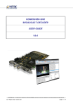
Functional Diagram
A functional diagram of the PVD 5660 is shown on the next page.
Page 28 of 79
P VD 5660 Reference Manual. Rev 2.6
Page 29 of 79
P VD 5660 Reference Manual. Rev 2.6
Module Layout
Module Front Panel
Two versions of the PVD 5660 are available:
PVD 5660 B = BNC connectors for unbalanced AES3id
PVD 5600 D = SubD connector for balanced AES3
Module Rear Termination Panels
Cooling Fans
Note. Cooling fan operation is monitored and alarmed with the module alarm
LED and also within the LYNX control system.
Page 30 of 79
P VD 5660 Reference Manual. Rev 2.6
Connections
Video
The PVD 5660 uses standard 75 Ohm BNC connectors. We recommend the use of high
quality video cable for digital video connections to reduce the risk of errors due to
excessive cable attenuation. Max cable lengths the module will support are shown below.
SDTV = 250m Belden 8281 (270Mbits/s)
HDTV = 140m Belden 1694A (1.4Gbits/s)
Note. Due to the compact design of the connection plate it will be necessary to
use a connection tool to secure the BNC video connectors.
External Audio (AES)
The module provides for both Unbalanced (AES3id) and Balanced (AES3) external audio
connections.
The PVD 5660 B version provides BNC connections for unbalanced AES3id
The PVD 5660 D version provides a SubD connector for balanced AES3
Connections for the SubD connector are provided below
Pin Number
1
2
3
4
5
6
7
8
9
10
11
12
13
Connection
AES 4 out +
AES 4 out GND
AES 3 out AES 2 out +
AES 2 out GND
AES 1 out AES 4 in +
AES 4 in GND
AES 3 in AES 2 in +
AES 2 in GND
AES 1 in n.c.
Pin Number
14
15
16
17
18
19
20
21
22
23
24
25
Connection
AES 4 out AES 3 out +
AES 3 out GND
AES 2 out AES 1 out +
AES 1 out GND
AES 4 in AES 3 in +
AES 3 in GND
AES 2 in AES 1 in +
AES 1 in GND
View looking INTO connector as seen on module
We recommend you use high quality screened (twisted pair) cable for the balanced audio
connections.
Page 31 of 79
P VD 5660 Reference Manual. Rev 2.6
Installation
If this module was supplied as part of a system it is already installed in the rack
enclosure. If the module was supplied as a field upgrade please follow the installation
procedure below.
NOTE Observe static precautions when handling card. Please see ESD
warnings on Page 7.
This module has a double width rear connection panel, meaning it will occupy two slots of
a standard Series 5000 Card Rack. This is to accommodate the additional connections
needed for this module and to also provide adequate space for cooling in the rack. Up to
five P VD 5660 modules can be accommodated in a single Series 5000 rack frame.
NOTE. When using this module the R FR 5011 or R FR 5012 Fan Front Rack
Frame should be used which provides additional airflow into the rack. If you plan
to install this module into empty slots in an existing rack with no fan front cover then please purchase the R FR 5001 Fan Front update kit.
Each Card Module is supplied with a rear connection panel and mounting screws. Please
follow the procedure below for the installation of the card module into the Series 5000
Card Frame.
We recommend you power the rack down before installing any additional modules into an
existing card frame.
1. Select a free two slot space in the card frame where the CardModule will be
located.
2. Remove the blank connection panels from the rear of the rack (if fitted)
3. Install the rear connection panel using the screws supplied. Do not tighten the
screws fully
4. Slide the card module into the card frame and carefully check the CardModule
connects to the rear connection plate. The card should fit easily and should not
require excessive force to insert - if you feel any resistance, there could be
something wrong with the rear connection panel location. Do not try and force
the connection this may damage the connectors. Remove the rear connection
panel and check alignment with the CardModule.
5. Insert and remove the CardModule a few times to ensure correct alignment and
then tighten the two screws to secure the rear connection plate.
6. Power up the rack and check the module LED’s and matrix display illuminate.
Check the module is automatically logged into the control system device tree.
(It may take a few seconds for the control system to “discover” the new module)
NOTE. The use of the optional control system is mandatory for the
control and setup of this module. If you do not have the control system,
then please contact your LYNX representative for details on how to
upgrade your installation with the LYNX control system.
Page 32 of 79
P VD 5660 Reference Manual. Rev 2.6
Firmware Options
The basic module is a single channel frame synchronizer and SDTV ARC with full audio
support, providing four user mapped outputs. With the addition of the following firmware
options the performance and features of the module can be greatly enhanced and
customized to meet a specific application.
Note. Firmware options can be added at any time by simply purchasing and
installing a license code string. No hardware or firmware modifications are
needed.
For information on how to install a licensed option please refer to the GUI section of this
manual.
Second Input Option (OC-5660-SCND)
The addition of this option will enable the second input and provide a second channel of
frame synchronization. This also includes a 16 channel de-embedder with 16 additional
inputs into the integrated AES input crossbar.
It is possible to switch seamlessly between the two inputs (clean switch) which can be
configured to trigger via GPI input or can be switched via the control system.
Note: Both frame synchronizers are connected to the single reference input used
for the module
Page 33 of 79
P VD 5660 Reference Manual. Rev 2.6
Down Conversion Option (OC-5660-DWN)
With the addition of this option, basic HDTV to SDTV down conversion capability is
added to the module (2 instances are required to provide two internal channels of down
conversion). These converter(s) are individual internal resources which can be routed to
any input signal and any of the four available outputs. Modes of operation are described
below.
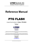
Letterbox
This takes the 16:9 aspect ratio of the input HD signal and fits it into the 4:3 SD aspect
ratio screen with black bars at the top and bottom of the image.
Center Cut
This mode cuts the center portion of the 16:9 input signal and fills the 4:3 SD aspect ratio
screen.
Stretch to Fill
This mode takes the 16:9 input signal and distorts (vertically stretches) the image to fit
the available 4:3 SD aspect ratio space.
16:9 HDTV Source
4:3 Center Cut
4:3 Letterbox
4:3 Stretch to fill
Page 34 of 79
P VD 5660 Reference Manual. Rev 2.6
Up/Down/Cross Conv. Option (OC-5660-UPXD)
The addition of this option adds a single channel of high quality up, down and cross
conversion to the module (which can be used in addition to the basic down conversion
options if installed). This is an internal resource which can be routed to any input signal
and mapped to any (or all) of the four available outputs. Modes of operation are
described below.
Note : Operation mode is switchable i.e. Up Conversion OR Down Conversion
OR Cross Conversion.
Down conversion
Down conversion modes are as described previously for the basic down conversion
option.
This converter also adds a 14:9 conversion
Up Conversion
The UP converter will convert the connected SDTV input standard to the selected HD
Standard within the same or half the frame rate. See below
525 / 59.94Hz Input Signal Converted to 1080i / 59.94Hz or 720P / 59.94Hz
625 / 50Hz Input Signal Converted to 1080i / 50Hz or 720P / 50Hz
Modes of operation are as follows:
Center Cut
This mode cuts the horizontal center portion of the 4:3 SD input signal and fills the 16:9
HD aspect ratio image area. (top and bottom of image are cropped)
PillarBox
This takes the 4:3 SD aspect ratio of the input signal and fits it vertically into the 16:9 HD
image area with black bars at the left and right of the image.
Stretch to Fill
This mode takes the 4:3 SD input signal and distorts (horizontally stretches) the image to
fit the available 16:9 HD image area.
14:9 Conversion
This mode takes the 4:3 SD input signal and distorts (horizontally stretches) the image to
fit the available 14:9 HD image area.
Page 35 of 79
P VD 5660 Reference Manual. Rev 2.6
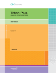
Cross Conversion
When used in cross conversion mode the module will cross convert the video signal
between formats within the same or half the frame rate. Please refer to the table below
for supported conversion modes.
Green (Y) = Supported mode, White (empty) = Not supported mode, Grey = Not applicable
Image size and Positioning
This option also provides the ability to manually adjust the image size and position of the
converted output. For more information on the controls and use of this feature please
refer to the GUI section of this manual for more details.
Note: The converters can be automatically controlled by AFD (Active Format
Description), WSS (Wide Screen Signaling) and VI (Video Index). Please refer to the GUI
section of this manual for more information of the controls provided and how to use them.
Color Space Conversion
The conversion options also provide integrated color space conversion capability which
will automatically compensate for the conversion of the wider 709 HD color space into the
more narrow 601 SDTV color space or vice versa ensuring legal color reproduction.
NOTE. Color space conversion can be bypassed, or set to process only the
chrominance part of the signal if desired.
Note: If this option (OC_5660_UPXD) is activated the detail Enhancement is
active (please see page 37)
Page 36 of 79
P VD 5660 Reference Manual. Rev 2.6
Noise Reduction (optional: OC-5660-NR)
The module provides optional Noise Reduction functionality for one channel:
The adaptive noise reduction function processes the input data in either progressive or
interlaced format. Application of noise reduction to noisy interlaced signals can optimize
the de-interlacer performance.
General Noise Reduction
General noise reduction comprises of both adaptive 2D and 3D noise reduction. 3D noise
reduction corrects for temporal and spatial noise; and 2D noise reduction corrects spatial.
3D noise reduction is applied to any interlaced or progressive signal with a pixel rate less
than or equal to 75Mp/s. 2D noise reduction is applied to any interlaced or progressive
signal. The selection of 2D or 3D noise reduction processing is automatically controlled
by the firmware in accordance with the video signal being processed.
Block Artifact Reduction
Block Artifact Reduction (BAR) locates and reduces block edges produced by DCT based
compression processing. BAR can be applied to any interlaced or progressive input
signal.
Mosquito Noise Reduction
Mosquito Noise Reduction (MNR) dynamically adapts to image content, effectively
reducing mosquito artifacts around sharp edges in DCT based compression. It can be
applied to any interlaced or progressive signal.
Detail Enhancement (Sharpness and Texture)
The detail enhancement function provides both sharpness and texture enhancement,
realized by adaptive horizontal, vertical and diagonal large edge and small edge
enhancement processes. Overshoot / undershoot control is provided to minimize ringing
on the enhanced edges. In addition, noise rejection is provided to minimize the amount of
enhancement applied to the noisy areas of the image.
For ease of use the various controls are combined into two parameters: Level and
Threshold:
• Level: controls the level of the horizontal, vertical as well as the diagonal high
pass filtered picture content, which will be added to the original signal again, i.e.
the gain of the high frequency content in the signal.
• Threshold: This parameter controls the level of signal which is passed through
for level control, i.e. all amplitudes in the signal below this threshold will not be
used for the detail enhancement.
Note: Detail Enhancement is also active if the option OC_5660_UPXD (HQ
Up/Down/Cross Converter is activated
Page 37 of 79
P VD 5660 Reference Manual. Rev 2.6
Settings and Control
The P VD 5660 module has an integrated micro-controller, which enables the module to
be configured and controlled locally using the multifunction switch and 4 character dot
matrix display, or from remote using a GUI interface when using one of the optional
controllers and control software.
!
NOTE. This module is extremely compact and flexible with hundreds of possible
user settings. It is not practical to make all these settings available on the local
dot matrix display. The use of the control system is mandatory to access the
vast array of settings possible. Please refer to the GUI section of this manual for
details on the control provided. Some rudimentary module settings are possible
via the local controls, which are detailed below.
Once set, all settings are automatically saved in non-volatile internal memory. (Flash
RAM) The module will always recall the last used settings.
Multi-function Switch
Side
Front
Switch Operations
Up
Down
Enter
Multi Function Switch
The CardModule is equipped with a multi-function switch located on the front bottom
edge of the card. (See above)
Using the Local Display Menus
Making local adjustments to the module is done using the multifunction switch and the
integrated 4-character dot matrix display. The menu system is layered, and navigation
through the system is done using the UP and DOWN functions of the switch. ENTER is
used to move between menu levels and also enter a selection.
Switch Function
UP
DOWN
ENTER
Operation
Move UP within a level
Move down within a level
Change levels / Make selection
Page 38 of 79
P VD 5660 Reference Manual. Rev 2.6
Menu Structure
The Menu structure is defined in the next table, and can be used to help navigating
through the menu system.
ENTER moves between levels
UP/DOWN moves between items within the level
When a new setting is entered the system will jump back one level in the menu system.
LEVEL 1
•
The “back” selection in the menu structure will take you back one level when
selected.
•
When an item is selected which has several setting possibilities the first value
displayed will be the value currently stored in the system. The order of the
available settings for any menu item in the table supplied does not represent the
order the settings will actually be displayed.
•
If left unattended, the menu will default to the root display after a short timeout.
LEVEL 2
LEVEL 3
P VD 5660
Notes
Root Display
REF
Reference Selection
EXT
Reference taken from module rear connection panel
INT
Reference taken from common rack reference
back
FPS
Output frame rate selection
ODD
All outputs jammed to 59.94Hz, 23.98 Hz or 29,97 Hz frequency frame rate*
EVEN
All outputs jammed to 50Hz, 24 Hz, 25, 30 Hz or 60 Hz frequency frame rate*
AUTO
Output frame rate is derived from connected reference (default)
back
RSET
Reset Factory Defaults
NO
YES
Reset factory defaults
back
back
* This is for facilities which operate in a single fixed format and wish to maintain this
constant output frame rate at all times (regardless of the connected reference signal, or
any disturbance to the connected reference signal). This will prevent the output frame
rate and format automatically “tracking” the connected reference standard should this
change. The output video signal will maintain the “jammed” to the video frame rate but
the video will be disturbed if the input reference signal changes.
Page 39 of 79
P VD 5660 Reference Manual. Rev 2.6
LED Status Indicators
The P VD 5660 module has LED indicators that serve as alarm and status indication for
the module. Function is described below.
SDI 1 Status LED 1
LED Color
Green
Yellow
Red
Indication
SDI 1 Present and OK
SDI 1 Frame Rate Mismatch
(Mismatch between the fixed output frame
rate and the SDI input. Conversion taking
place)
No SDI 1 Signal Connected
SDI 2 Status LED 2
LED Color
Green
Yellow
Red
Indication
SDI 2 Present and OK
SDI 2 Frame Rate Mismatch
(Mismatch between the fixed output frame
rate and the SDI input. Conversion taking
place)
No SDI 2 Signal Connected
Ref Status LED 3
LED Color
Green
Yellow
Red
Indication
Reference Present
Reference Present, but not used
(Module is set to free run with no lock to
external reference)
Reference not present – but required
(Module is set to “lock to reference”)
ALARM LED
LED Color
Green
Yellow
Red
Red Flashing
Indication
Normal Operation
Problem with one of the SDI inputs
Problem with both SDI inputs
Cooling Fan Failure
Note. The Alarm LED can be seen with the rack front cover fitted
Page 40 of 79
P VD 5660 Reference Manual. Rev 2.6
Control System GUI
All LYNX CardModules support a computer interface which allows setting the modules
parameters using a simple GUI interface. Access to all standard features and in some
cases extended features is possible using this interface. The complex nature and
extensive user settings provided on the PVD 5660 requires the use of the control
system.
Note. Any settings made using the control system overrides any local settings
made on the module. All settings are stored in internal flash ram and will survive
power cycles and long term storage.
The following GUI screenshots and descriptions shown below describe the settings and
adjustments possible for the PVD 5660 CardModule.
The above screenshot shows the complete module GUI. The Device info area contains
information about the module including name and firmware revision. If used as part of a
larger system (using the LYNX central control system) the modules position and physical
location is displayed above the “locate” button.
Note. The Locate function is a tool used to quickly identify a module in larger
systems. Selecting “locate” will flash the module alarm LED yellow. (This does
not effect module operation)
The first screen displayed when the module is selected is the Main Tab this is a graphical
representation of the modules overall function and signal flow (left to right). Clicking on
the processing boxes will link to other GUI screens with more controls for these specific
functions.
The area at the bottom of the screen is the error log. Any fault condition (or event) will be
time stamped and entered into the log.
There are a number of “Tabs” along the top of the screen which splits up the module
settings into a number of logical displays. The various GUI screens and primary functions
are described below.
Page 41 of 79
P VD 5660 Reference Manual. Rev 2.6
Main Tab
This screen is the main interface and is presented first when the module is displayed in
the GUI. The layout replicates module “block” functions and signal flow from left to right.
The primary purpose of this screen is to show the overall signal flow through the module
and allow easy navigation to other areas. Input standards and formats are auto detected
and displayed in the GUI. Parameters will be annunciated in different colors to show
status (green = good, red = problem, yellow = caution etc).
REF in Select
There is a select list next to the REF in connection. This selects if the reference signal is
to be used from the common rack reference input (intern(rack)) or the board connection
plate reference input (extern(board)). The reference for the frame synchronizer can also
be derived from the digital inputs. This is useful for applications where the P VD 5660 is
used as a video delay line.
Signal Routing
In the center of the screen there is an area where the internal signal routing can be
changed. This area is fundamental to the modules flexibility and function. Here the
internal video signals can be routed through (or bypassing) the internal resources
(Up/down/cross conversion options / ARCs etc). Selecting a cross point via the radio
button closes the connection (operation is self explanatory)
Page 42 of 79
P VD 5660 Reference Manual. Rev 2.6
Video Proc Tab
General Video Settings
The first area covers some General setup parameters for the frame sync operation.
External Reference Source
It is possible to take the external reference signal from three sources. Either from the
common rack reference (an external reference connection to the rack frame which is fed
to all cards installed in the rack) or via the BNC connection provided on the module rear
connection panel, or from either of the two video inputs. Selections provided are:
•
•
External (board) = Via module rear connection panel
Internal (rack) = Common rack reference
Frequency Pre-select
This is where the frame synchronizer output frequency (or frame rate) is selected. This
can be jammed into a frame rate which will never change to maintain this constant output
frame rate at all times regardless of the connected reference signal, or any disturbance to
the connected reference signal. This will prevent the output frame rate and format
automatically “tracking” the connected reference standard should this change. The output
video signal will maintain the “jammed” to the video frame rate but the video will be
disturbed if the input reference signal changes.
Page 43 of 79
P VD 5660 Reference Manual. Rev 2.6
It is also possible for the synchronizer to configure the output frame rate based upon the
connected reference. This is the default setting for the module. Possible settings are:
•
•
•
Even (24, 25, 30 or 50 Hz)
Odd (23,98, 29,97 or 59,94 Hz)
Follow (last) reference (default)
Note. The synchronizer is supplied from the factory with the last stored reference
as 50Hz. With no reference connected its possible to change the last stored
reference to something else. Simply select the desired fixed frequency and then
re-select “follow last reference”. Now the module will use this new setting through
a power cycle
Also, this value will not be restored to 50Hz following a “Restore Factory
Defaults” operation, the stored setting is preserved.
The “Current Frequency” area in the GUI is showing the frequency the frame
synchronizer is running in currently (useful if the follow last reference selection is made)
Freeze Mode
This is where the reaction of each channel is defined in
the case of excessive video errors (TRS Errors). The
output can be configured to freeze (“Freeze on TRS
Error”) or pass the input signal transparently when
excessive errors are encountered. If configured to pass
video transparently (“Transparent”) then all video errors
and disturbances are passed from the input to the output.
The synchronizer is very robust in its ability to handle
poor quality input signals but there may be occasions
where excessive errors cannot be recovered by the
synchronizer. This is generally qualified by TRS errors.
TRS means “Timing Reference Signals” and is a sequence of digital values embedded in
the SDI data streams. If the frame synchronizer cannot recover these errors, then the
channel will freeze the video until the errors can be recovered. One function of the
synchronizer is to repair any bad TRS values ensuring a stable and technically correct
video stream is delivered on the outputs. Selections for each channel are as follows:
•
•
Freeze on TRS errors
Transparent
Note. The function of the freeze operation is defined in each output video proc
stage (Freeze Mode).
Page 44 of 79
P VD 5660 Reference Manual. Rev 2.6
Synchronization Mode
Three different modes of synchronization can be
selected:
Frame Synchronization: The input signal is always
buffered for 1 frame. TRS errors can be hidden
with a freeze frame of the last valid frame. Also
repeat frames in case the input clock is lower than
the reference clock will be generated from the last
buffered frame
Delay input to output is always minimum 1 frame
plus the timing difference of input signal to
Reference
Line Sync (H): In case of clock synchronized signals the Line synchronizer H mode can be
activated to achieve minimum delay. The input signal is buffered for 1 line to correct timing
differences within 1 line
A minimum delay of approx. ½ line before the start of the next line has to be maintained to
compensate for the processing delay of the P VD 5660.
Line Sync (V): In this mode the synchronizer delays the input signal towards the next frame
start to achieve horizontally and vertically aligned pictures. The delay is then the timing
difference of the input signal to the Frame Pulse of the Reference. This results in frame
aligned signals without the additional 1 frame delay of the frame synchronizer mode.
A minimum delay of approx. ½ line before the start of the next frame has to be maintained
to compensate for the processing delay of the P VD 5660.
For distortion free switching in front of the P VD 5660, e.g. in a router, all signals have to be
in area “I” or all signals in area “II”.
Area “II” is a window for line synchronization of 2.5 lines (HD) and 4.5 lines (SD).
Area “I” is an extension of the standard line synchronization to allow for “infinite” line
synchronization. As this extended functionality is buffered differently, distortion free
switching is only possible within these two areas.
To adjust the timing of video signals relative to the reference to avoid larger delays the
video output delay function can be used (see page 60). This shifts the video signal into the
required area. This adds the manually adjusted delay, but avoids the additional frame
delay, e.g. if a signal is in the area of the minimum delay.
Page 45 of 79
P VD 5660 Reference Manual. Rev 2.6
Note: In line synch mode the converters are disabled, when converters are active frame
synch mode is required
Synchronous SDI Input (minimum audio delay)
If activated the embedded audio to video delay at the output is always minimal. This should
be used for clock synchronized signals only
DVITC Input Line Selection
DVITC Line Selection for the two DVITC Readers per input signal is provided. If a
specific line is selected the presence detection will indicate a DVITC signal only if
present in the selected line.
Selecting AUTO will enable a search for DVITC signals in any line.
NOTE: An AUTO search can take longer (up to 15 seconds)
See also Advanced Meta Data Settings (Page 51)
Page 46 of 79
P VD 5660 Reference Manual. Rev 2.6
Conv1 / Conv2 Tab
Video Converter 1 and 2 (OC-5660-DWN option)
This tab (identical for Converter 1 and Converter 2) will display the configuration screen
for the two basic down converters
(OC-5660-DWN option). This screen can also be accessed by clicking on the “Conv 1”
resp. “Conv 2” box in the flow diagram on the main GUI screen.
The down converter functionality in this section will only be active if the OC-5660-DWN
options (one for each down converter) have been purchased and installed.
Options are installed via a license string (purchased separately), these are entered into
the module to activate the options. Option licenses are managed / entered using the
Options Tab in the GUI.
The small graphics left and right per channel display directly the settings of the down
converter and the resulting output format.
Converter Source
It’s possible to select the signal source into each down converter. This is done using the
first drop down box “Source” This can be Input 1 or Input 2. (This can also be changed
using the signal router on the Main Tab)
Control Mode
The down converters can be automatically
controlled by AFD, WSS or VI. Selection is
made from the drop down box. Depending on
what codes are detected in the input signal and
the converted output format; the down
converters are automatically preset for this
mode of operation.
Page 47 of 79
P VD 5660 Reference Manual. Rev 2.6
Input Aspect Ratio
For SDTV inputs the aspect ratio (4:3 or 16:9) can be selected
Down Converter Mode
The down converter provides three modes which can be selected using the radio buttons
provided:
• Pillarbox / Letterbox
• Center cut
• Stretch to Fill
The “Input standard” and the “signal used in” indicate which input format is routed to the
specific conversion channel, and also indicates which of the four outputs the converter
output is routed to (these will change if the internal signal routing is changed).
Output Format
With this selection you can choose the output video format. The selections possible are
qualified by the frequency preselection (see Video Proc Tab, page 43) and the attached
reference signal. For SDTV output formats the aspect ratio can also be selected.
Inserted Format Description
With the three checkboxes you can select what type of format description will be inserted
into the video signal as metadata. This information is derived from the settings made to
the converters. If there was already metadata of this type inserted in the input signal they
will be overwritten (if the related checkbox is selected).
NOTE: If the checkbox is not selected then no data will be inserted and any existing data
will be blanked
SDTV Aspect Ratio Converter Mode
The Aspect Ratio Converter provides three modes for 16:9 to 4:3 conversion and three
modes for 4.3 to 16:9 conversions, which can be selected using the radio buttons
provided:
16:9 to 4:3 Conversion
• Letterbox
• Center cut
• Stretch to Fill (vertical)
4:3 to 16:9 Conversion
• Pillar Box
• Center cut
• Stretch to Fill (horizontal)
The “Input format” and the “signal used on” indicate which input format is routed to the
specific conversion channel, and also indicates which of the four outputs the converter
output is routed to (these will change if the internal signal routing is changed).
Page 48 of 79
P VD 5660 Reference Manual. Rev 2.6
Advanced Metadata Settings
On the left side all detected Meta Data is displayed, on the right side all (re-) inserted
Meta Data is displayed.
Note: The P VD 5660 is transparent for Dolby Metadata (S2020), if Dolby Metadata is
detected it will be displayed only in the input part of this window (left side).
To configure the insertion of Meta Data please activate the Checkbox “Advanced Meta
Data Settings” in the center.
The following screen will be shown, with the Meta Data Handling in the middle, this is
identical for all three converters in the P VD 5660:
Closed Captions:
Detected Closed Captions:
•
S334CDP: Closed Captions in S334 CDP transport packet (containing CEA-708
•
S334RAW: Closed Captions in S334 RAW transport packet (containing CEA-
•
Line21: Closed Captions in Line 21 (containing CEA-608 data, in 525 video
standard only)
and/or CEA-608 data)
608 data)
Detected Closed Captions transport packets are indicated with “present” with green
background.
Page 49 of 79
P VD 5660 Reference Manual. Rev 2.6
Closed Captions Re- Insertion:
Activating the respective checkboxes will enable the re-insertion of the different transport
packets into the converter output. Transport packets can be generated from different
incoming types.
A source priority selection with three levels for the three possible transport packets is
provided. If the “Primary Source” is not present, “Fallback 1” will be used, if this is also
missing as a source, “Fallback 2” will be used.
Note: If “Default Priority” is active, the Source Priorities are set as shown in the
left picture, i.e. the “Primary Source” is set to provide standard transparency
Time Code:
DVITC
Digital Interval Time Code (SMPTE 266M 2008)
Description
D-VITC is an 8-bit digital data representation of the band-limited analog signal
corresponding to the vertical interval time code (VITC) of SMPTE 12M and IEC 60461.
The 8 bits of D-VITC shall be carried in the 8 most significant bits of the 10 bits of the
ANSI/SMPTE 125M or ITU-R BT.601 coding. Since some equipment may be built using
only 8 of the 10 bits, both 10- and 8-bit interpretations of the values are given in this
standard, with 10 bits the preferred expression. DVITC is only present in SDTV
(525/625).
ATC
Ancillary Time Code (SMPTE 291M 2008)
Description
The acronym ATC refers to ancillary packets carried in the Ancillary space (VANC or
HANC) of a digital television data stream, as described in SMPTE 12M-2 (formerly
SMPTE RP 188), and payloads of these packets convey LTC or VITC codeword data.
Page 50 of 79
P VD 5660 Reference Manual. Rev 2.6
Detected Time Code:
ATC-LTC, ATC-VITC and DVITC will be detected if present in the incoming
video signal
Detected Time Codes are indicated with “present” with green background. For DVITC
also the insertion lines are indicated. For DVITC two insertions per video signals are
possible, normally the second insertion is a duplicate of the first one.
For ATC-VITC a DVITC Index is shown, indicating the original insertion line of the VITC
signal, which will be used if converted back to DVITC
In the Video Proc Tab a DVITC Line Selection for the two DVITC Readers per input
signal is provided. If a specific line is selected the presence detection will indicate a
DVITC signal only if present in the selected line.
Selecting AUTO will enable a search for DVITC signals in any line.
NOTE: An AUTO search can take longer (up to 15 seconds)
Time Code Insertion:
Activating the respective checkboxes will enable the insertion of the different time codes
into the converter output. The three time codes can be generated from different incoming
types.
A source priority selection with three levels for the three possible time code types is
provided. If the primary source is not present, Fallback1 will be used, if this is also
missing as a source Fallback 2 will be used.
Note: If “Default Priority” is active, the Source Priorities are set as shown in the picture
above, i.e. the “Primary Source” is set to provide standard transparency
Page 51 of 79
P VD 5660 Reference Manual. Rev 2.6
Note: DVITC is only present in SDTV
DVITC Line Select:
DVITC can be inserted twice (Inserter A and B) into the output signal with selectable line
numbers (line 6..22). See table below.
Page 52 of 79
P VD 5660 Reference Manual. Rev 2.6
Teletext
WST
World System Teletext
Description
Normally analog information designed mainly for PAL TV. In the context of the P VD 5660
it is an emulation of analogue teletext for digital TV.
S2031 WST
SMPTE 2031: Carriage of DVB/SCTE VBI Data in VANC
Description
This Standard specifies how to carry the digital values resulting from defined
standardized data streams carried in MPEG-2 Transport Streams (TS) as specified by
either DVB/ETSI EN 301 775 or SCTE 127 (or both) as ancillary data packets in the
vertical ancillary data space (VANC).
Note: In the P VD 5660 only teletext data (digital teletext data derived from WST) in the
data packets will be detected and processed
OP47 SDP
Free TV Australia Operational Practice OP- 47
STORAGE AND DISTRIBUTION OF TELETEXT SUBTITLES and VBI DATA FOR HIGH
DEFINITION TELEVISION
Description
Free TV Operational Practice OP-47 describes the technical/operational practices
associated with the storage and distribution of Closed Caption/Subtitling data in the
vertical ancillary space of the 10 bit serial HD-SDI signal complying with
ITU-R BT.1120-7.
Note: In the P VD 5660 only teletext data (digital teletext data derived from WST) in the
data packets will be detected and processed.
Teletext Decoder
Selecting the teletext tab will show the control window below:
The teletext decoder indicates what type of teletext is detected. A valid teletext is
indicated with a green background.
Page 53 of 79
P VD 5660 Reference Manual. Rev 2.6
A pre-selection can be set by clicking on the
text at the bottom of the decoder window.
This will open the Video Proc tab, where the
pre-selection can be set for the two inputs.
Teletext Encoder
The encoder is used for the insertion of
the teletext data into the respective
converter.
If WST teletext data is present / selected then the line numbers containing teletext data
on both the input and output are shown. The green designation indicates valid teletext
data is present.
Note: If S2031 or OP47 SDP Teletext is detected / selected then no line numbers will be
shown
Page 54 of 79
P VD 5660 Reference Manual. Rev 2.6
In automatic mode the output line numbers equal the input line numbers. Manual mode
has to be selected to change the output line numbers.
Manual Input to output line mapping can be changed by clicking on the respective line
number
The encoder always tries to map the same input line to output line, in our example above
line 17 and 19 are not used on the output as they were not used in the input. Clicking on
these line numbers would activate their use in the output.
Line numbers in light grey are already occupied by other metadata with analog origin
(e.g. DVITC).
If there is a conflict or problem, (e.g. one line gets lost), a warning in red will be shown as
indicated above.
Page 55 of 79
P VD 5660 Reference Manual. Rev 2.6
HQ Scaler Tab
The OC-5660-UPXD option is required for the HQ up, down and cross conversion
functionality.
For the basic module without the OC-5660-UPXD option installed this converter provides
the HQ SDTV Aspect Ratio Conversion functionality. Please see section “Aspect Ratio
Conversion Mode” above for functionality.
If the OC-5660-UPXD option is activated this also provides Down Conversion
functionality as described previously.
The screen below shows the controls provided for the HQ Up, Down, Cross and Aspect
Ratio Conversion.
HQ Scaler Source
This selection allows the input source to the scaler to be selected, this can also be set
using the signal routing selections on the Main Tab. Selections possible are “Input 1” and
“Input 2”
Control Mode
The converter can be automatically
controlled by AFD, WSS or VI. Selection is
made from the drop down box. Depending on
what codes are detected in the input signal
and the converted output format; the
converter is automatically preset for this
mode of operation.
Page 56 of 79
P VD 5660 Reference Manual. Rev 2.6
Input Aspect Ratio
For SDTV inputs the aspect ratio (4:3 or 16:9) can be selected
Output Format
With this selection you can choose the output video format. The selections possible are
qualified by the frequency preselection (see Video Proc Tab, page 43) and the attached
reference signal. For SDTV output formats the aspect ratio can also be selected.
Inserted Format Description
With the three checkboxes provided you can select what type of format description will be
inserted into the video signal as metadata. This information is created depending on the
settings of the converters. If there was already metadata of this type inserted it will be
overwritten (if the related checkbox is selected).
NOTE: If the checkbox is not selected then no data will be inserted and any existing data
will be blanked
Conversion Mode
With the selection box in the middle of the screen the conversion mode can be selected.
The check box “motion adaptive” filtering is used to improve picture quality for moving
images and reduces motion blur, and should be selected for normal use. For still images
and conversion from progressive to progressive standards the checkbox should be
switched off.
Input Cropping
With these controls it’s possible to crop the input image which will be used for conversion
(cropping will appear on the converted image output). To use this function the “advanced
settings” checkbox has to be activated.
Output Cropping
With these controls the size and positioning of the output image can be set. Any parts of
the image which has no content (cropped on the input or outside the image extents if
shifted or made smaller) will be filled with black. To use this function the “advanced
settings” checkbox has to be activated.
Note. It is also possible to manually drag the input and output cropping extremities using
the mouse pointer on the GUI. Simply position the mouse over the green line you wish to
move, click and drag the line to the desired point on the image.
Drag Green Lines with
mouse
Note. If a non-standard setting is used, the Conversion setting will jump to “custom”
Page 57 of 79
P VD 5660 Reference Manual. Rev 2.6
Noise Reduction Tab
High Quality Noise Reduction (OC-5660-NR option)
The OC-5660-NR option is required for the HQ Noise Reduction functionality.
The screen below shows the controls provided for this function..
The adaptive noise reduction function processes the input data in either progressive or
interlaced format. Application of noise reduction to noisy interlaced signals can optimize
de-interlacer performance.
General Noise Reduction
General noise reduction comprises of both adaptive 2D and 3D noise reduction. 3D noise
reduction corrects for temporal and spatial noise; and 2D noise reduction corrects spatial.
3D noise reduction is applied to any interlaced or progressive signal with a pixel rate less
than or equal to 75Mp/s. 2D noise reduction is applied to any interlaced or progressive
signal. The selection of 2D or 3D noise reduction processing is automatically controlled
by the firmware in accordance with the video signal being processed.
Block Artifact Reduction
Block Artifact Reduction (BAR) locates and reduces block edges produced by DCT based
compression processing. BAR can be applied to any interlaced or progressive input
signal.
Mosquito Noise Reduction
Mosquito Noise Reduction (MNR) dynamically adapts to image content, effectively
reducing mosquito artifacts around sharp edges in DCT based compression. It can be
applied to any interlaced or progressive signal.
Detail Enhancement (Sharpness and Texture)
The detail enhancement function provides both sharpness and texture enhancement,
realized by adaptive horizontal, vertical and diagonal large edge and small edge
enhancement processes. Overshoot / undershoot control is provided to minimize ringing
Page 58 of 79
P VD 5660 Reference Manual. Rev 2.6
on the enhanced edges. In addition, noise rejection is provided to minimize the amount of
enhancement applied to the noisy areas of the image.
For ease of use the various controls are combined into two parameters: Level and
Threshold
• Level: controls the level of the horizontal, vertical as well as the diagonal high
pass filtered picture content, which will be added to the original signal again, i.e.
the gain of the high frequency content in the signal.
• Threshold: This parameter controls the level of signal which is passed through
for level control, i.e. all amplitudes in the signal below this threshold will not be
used for the detail enhancement.
Output Proc Tabs
There are four “Out Proc” tabs provided, one for each of the four outputs provided. This is
where the individual video processing functions are set for each channel. All four tabs
have identical adjustments.
Color Space Conversion
Note. This is only active when the conversion option(s) are installed (OC-5660DWN and/or OC-5660-XUPD)
This is where the color space conversion functionality is configured. This is used to
ensure correct color reproduction on the outputs. HD color space is wider than SDTV
color space so there is the possibility of some illegal colors being reproduced if the color
space is not converted. Possible selections (only for the two down converts, automatic for
HD Converter) are:
• Convert (convert the video signal)
• Bypass (perform no conversion)
• Luma in Bypass (only convert Chroma portion of signal)
Page 59 of 79
P VD 5660 Reference Manual. Rev 2.6
Aperture Correction
Horizontal aperture correction is provided for each output channel, which can be used to
sharpen or soften the video signal. (This is sometimes required for down converted video
signals as the filtering process rolls off the high frequency very slightly). If adjusted in the
positive direction this will increase sharpness, if adjusted in the negative direction this will
soften the image.
There is a check box to switch aperture correction ON and OFF and an adjustment range
The numerical adjustment range provided is + 80 to -30, and is changed by clicking on
the “+” or “-“ Buttons.
Note. Aperture correction OFF is the same as a Zero setting in the adjustment
range
Clip CR/Cb Headroom
If activated all Luminance (Y) values below 64 and above 940, and all Chrominance
(Cr,CB) values below 64 and above 864 will be clipped.
H and V Blanking
A checkbox selection is provided for H (Horizontal) and V (Vertical) blanking. When
selected the video output will have new blanking applied in both of these areas (which will
overwrite any information in the vertical and horizontal blanking intervals).
Video Output Delay Adjustment
Each video output can be delayed relative to the reference sync up to a maximum of 3
frames. This is usually used for downstream system timing applications. The delay is
adjustable in the following increments:
•
•
•
•
Frames
Lines
Pixels or
Total Delay in ms
Depending on preferences you can use one or all of the adjustments provided to set the
total video delay.
Note. The adjustable delay applied is in addition to the fixed processing delay of
the module. Please refer to the tables provided in the “Fixed Video Processing
Delays” section for more information on processing delays.
Note: Using the “Fixed Processing Time Time” makes sure the processing delay is
always the same (max.delay). This function can be activated in the “OutProc” Tab of the
respective output or on the “Timing” Tab.
Settings
This area is where the freeze function is defined and also the action (and settings) of the
integrated test pattern generator. (Each channel has its own independent test pattern
generator)
Output if no input
Here the behavior of the P VD 5660 can be selected if no input is present
Page 60 of 79
P VD 5660 Reference Manual. Rev 2.6
•
•
•
Freeze
Black
Test Pattern
Freeze Mode
When the synchronizer encounters excessive TRS errors it can be set to freeze or pass
the video transparently (selected on the Video Proc tab). If Freeze is selected then the
behavior of the freeze function is selected using the drop down selections. These are:
•
•
•
Freeze Field 1
Freeze Field 2
Freeze Frame
Test Pattern Pre-select
A wide range of patterns is provided which can be selected using the drop down selection
provided. The pre-selected pattern will be used if the freeze mode is set to “test pattern”
and will also the pattern used if “test pattern on” is selected. Patterns provided are:
•
•
•
•
•
•
•
•
•
•
•
•
Full field Black
Full field White
Full field Yellow
Full field Cyan
Full field Green
Full field Magenta
Full field Red
Full field Blue
15% Grey (full field)
75% Color bars
75% Color bars over Red
Pathological PLL/EQ
Test Pattern Standard
With no input signal connected the module can be used a stand alone test generator
using this selection is possible to configure the test pattern into any of the supported
standards, or it can be set to follow the last input standard. Settings provided are:
•
•
Follow last input (default)
Fixed standards (half, same or double or current reference frame rate)
Test Pattern Enable
This checkbox simply switches on the pre-selected test Pattern. Activated test pattern will
be indicated on the Main Tab.
Video Adjustments
Four on screen sliders are provided to allow for the adjustment of individual video
parameters. Separate sliders are provided for video Brightness (gain), Saturation,
Pedestal (Black level) and Hue.
Default (null) settings are 0% (this is the default). Sliders can be quickly returned to the
factory null (or transparent) settings using the buttons provided at the bottom of each
slider.
Page 61 of 79
P VD 5660 Reference Manual. Rev 2.6
Timing Tab
All manually adjustable delays for audio and video can be set in the GUI shown below.
The video delay can be adjusted for the four SDI outputs independently.
If the Fixed Processing Time is enabled the respective output is always set to the
maximum possible delay (4 frames) independent from the mode of processing.
The manually adjustable delay is then deactivated (greyed out). The Fixed Processing
Time can be set independently for the four outputs.
The audio delay can be set at various positions:
SDI in:
SDI out:
AES in:
AES out:
Delay of the embedded audio after de-embedding
Delay of audio for re-embedding
Individual delays for the four AES inputs
Delay at AES outputs
Setting of the audio delay “SDI in” and “SDI out”
can be performed in a pop-up window, when
clicking on the deembedder/embedder blocks
Note: The Synchronizer will auto track the audio
delay to the video processing delay. The
adjustments provided here are offsets relative to
the internal tracking delay.
The audio delay offset can be set at various
positions as graphically shown in the audio
processing chain. Clicking the + and – buttons
adjusts the setting. Audio Delay Range is 0.330
seconds total (input to output, set in ms)
Page 62 of 79
P VD 5660 Reference Manual. Rev 2.6
The external AES outputs can be linked to one of the auto tracking delays of any of the
four SDI outputs using the drop down box “Output Tracking” shown.
Use the drop down list provided to link the four external
AES outputs to one SDI output channel auto tracking
delay value.
Select “none” to disable auto tracking delay for the
External AES outputs
Note: In case of detected Dolby E signals the input audio delay (AES in or Deembeeders) will be deactivated (control is greyed out) as this delay would be “re-aligned”
by the Dolby E Synchronizer again.
Audio Delay Pulse
The Audio Delay Pulse is connected through a BNC connector with TTL levels
Please select the related SDI output with the drop down list provided.
Page 63 of 79
P VD 5660 Reference Manual. Rev 2.6
AES Input Crossbar Tab
The complete audio payload (8 x AES) is de-embedded from each input channel and 4
external AES inputs can be applied to the module. All the audio is fed into an AES audio
cross bar which is configured using the GUI below.
The crossbar arrangement is simple; the inputs from the two de-embedders for each SDI
signal come in from the top. The external AES inputs come in from the bottom. All audio
inputs are the vertical component of the crossbar. The audio pathways out of the
crossbar are horizontal. Routing an AES pair is achieved by clicking on the cross point
with the mouse cursor.
Automatic Audio Detection
Audio presence and audio format for the embedded audio on the 2 SDI inputs and the 4 x
external AES inputs is automatically detected and displayed on the module GUI in the
LYNX control system.
This can be seen below; the small blocks under the de-embedder indicate the audio
status for each AES stream:
P = PCM Audio Detected
E = Dolby E Audio Detected
D = Compressed Audio Stream
Detected(other than DolbyE)
Blank = No Audio Signal Present
Page 64 of 79
P VD 5660 Reference Manual. Rev 2.6
In this example you can see input 2 has no audio present, and input 1 has the following:
AES 1 = PCM Audio
AES 2 = Digital Audio Stream
AES 3 = Dolby E Audio
AES 4 = PCM Audio
AES 5 = PCM audio
AES 6 = PCM Audio
AES 7 = No Audio Present
AES 8 = No Audio Present
Configuring Audio Inputs
Audio inputs can be configured
automatically based on the audio
detected, or manually configured to
be only a particular type. When an
input is manually configured the
system will indicate when a conflict
exists between the configured setting
and the detected audio on that
channel.
Clicking on one of the audio boxes
with the mouse will bring up the
audio configuration dialog for that
channel.
The default setting is always automatic, as seen above and for this first input you can see
it has detected PCM audio.
To manually set this input simply click
on the respective selection with the
mouse
In this case you can see input 1 has
been manually configured for PCM
audio, and it is highlighted green to
indicate it is a manual selection, and
there is no conflict. (a box with a letter
inside which is not green indicates
this channel is configured for
automatic detection)
If we manually force this input to DolbyE, this will cause a conflict as PCM audio is
present. See below:
Here you can see the conflict is
flagged by turning the box yellow. This
is indicating the channel is manually
preset for Dolby E, but the audio
format is in conflict with this setting, in
this case PCM audio. Note. Even
though there is a conflict the actual
audio present is passed through the
system – i.e. it is not blocked.
Page 65 of 79
P VD 5660 Reference Manual. Rev 2.6
Maintaining DolbyE Transparency
The PVD 5660 can process and synchronize DolbyE signals transparently, but some
care needs to be taken as to the routing of the DolbyE signals (or any compressed audio
bit stream) through the module. To help maintain transparency the module will
automatically bypass any processing stages which might corrupt this signal, and also
provide a warning indication in the GUI (indicating there is a possible problem with the
specified routing of this signal in the module)
For example, if DolbyE audio is routed through any of the inputs in audio Pathway 1 there
are three areas of concern. b) The sample rate converters, b) the audio processing stage
c) Synchronization and DolbyE guard band timing.
The module will automatically disable the sample rate converter and bypass the audio
processing for this channel in the Audio Processing amp (controls will be greyed out) – so
in this case the DolbyE signal will be passed transparently and is ready for re-embedding
into the outputs (or passing to an external output). However audio Pathway 1 does not
have any DolbyE synchronization capability, so the DolbyE audio will not be
synchronized and also the guard-band timing could be incorrect. To indicate this conflict
a small warning symbol is inserted into the audio line in the control system GUI. See
below:
Here you can see DolbyE from input 2 has been routed
into audio Pathway 1, channel 2
The module has inserted the warning symbol. Note. The
module has automatically greyed out the sample rate
converter and has also disabled the downstream audio
processing (not seen here)
A better choice for signal this DolbyE signals is Pathway 3, as this is designed for DolbyE
and includes 4 x DolbyE synchronizers and will always maintain the correct guard-band
timing.
Another area of concern for DolbyE or compressed audio streams is the mono audio
output crossbars. These should not be changed from the default setting for these types of
signals. The Module will also provide a visual warning if any of the mono cross points are
in conflict.
Here you can see the highlighted cross-point has been
manually changed from its default settings. The warning
symbol clearly indicates there is a conflict with this crosspoint setting for the audio signal present.
Note. For information on how to configure and switch mono
cross-points, please refer to the GUI section of the manual
Page 66 of 79
P VD 5660 Reference Manual. Rev 2.6
Pathway 1
The first 8 AES signals out of the crossbar (01…08) represent “Pathway 1” through the
Frame Synchronizer. These audio signals are fed through sample rate converters, (which
can be turned on and off using the check boxes).
This pathway also has full audio processing functionality available downstream in the
module.
Note. This pathway is not recommended for nonsynchronized DolbyE or encoded audio bit streams.
If Dolby E or other Audio Data signals are detected
this is indicated on respective audio channel. The
warning for Dolby E signals is indicating that
asynchronous Dolby E signals cannot be
synchronized through this pathway.
Pathway 2
The next 8 AES outputs from the crossbar (09…16) represent “Pathway 2” through the
synchronizer. These channels do not pass through any sample rate converters, and
audio passed through this pathway is assumed to be synchronous with the connected
reference signal (no audio synchronization is performed in the frame sync)
Pathway 3 – Dolby E
The next 4 AES outputs from the crossbar (17…20) represent “Pathway 3” through the
synchronizer. These channels contain 4 Dolby E synchronizers. This pathway allows
synchronization of asynchronous Dolby E signals.
The Dolby Synchronizers have to be referenced to one of the video outputs or the AES
audio outputs for correct guard band alignment.
This is done automatically when an audio signal through the Dolby Synchronizers is
selected for embedding or selected for the AES outputs.
Assignment of the Dolby Synchronizers to the outputs can be done manually by clicking
with the right mouse button on the respective Dolby Synchronizer and selecting the
output with the pull down list.
Page 67 of 79
P VD 5660 Reference Manual. Rev 2.6
If a Dolby synchronizer is used twice an alarm will be shown.
Clicking on the alarm sign will show a message.
Pathway 4 and 5
The next 4 AES signals from the crossbar (21..24) is “Pathway 4 & 5” and is dedicated to
SDI input 1. Any 4 of the 8 de-embedded AES streams can be selected and fed through
this pathway. The audio maintains its synchronization and timing references to the input
SDI signal and is not re-synchronized or processed by the module. The module is simply
de-embedding the audio and making it available as external signals.
Audio using these pathways can only be fed to the external AES outputs and cannot be
embedded back into the output video. (For example, you could use this pathway to deembed DolbyE and then feed it to an external DolbyE decoder)
“Pathway 5” is identical in function to Pathway 4 but dedicated to the second SDI input.
Page 68 of 79
P VD 5660 Reference Manual. Rev 2.6
AES Proc Tab
This provides access to the internal audio processing functions such as audio gain / mute
/ phase invert / overload and silence detection per audio mono channel (overload and
silence are indicated by color of the respective symbol: Green = OK Red = overload or
silence.
A mono mix down function per AES is also provided. This can be activated with the
checkbox “mixdown” at the right side.
Sample rate converters can also be selected or bypassed which are provided for the first
8 AES streams derived from the input audio crossbar
Note: If any Dolby E signal or other Audio data is passed through the processing stage,
the processing will be deactivated, so the audio data will not be modified (controls will be
greyed out). Settings will be set back to the original value if PCM audio will be switched to
the same path.
Page 69 of 79
P VD 5660 Reference Manual. Rev 2.6
AES Out Tab
This section is used to configure the external AES outputs. 4 outputs are provided and
any of the internal audio signals can be routed to the external outputs if required.
**Timing Zones
See Note below
All inputs to the crossbar are shown horizontally and the 4 x External AES outputs are
shown at the bottom of the screen. Selecting a cross point will route the required signal to
the selected AES output. There is also a “mute” function for each AES output if required.
When a cross point is selected it will select the AES pair (left and right channel) However,
these cross points are Mono in nature. Please refer to the section “Setting Mono Cross
Points” below for details on how to use the mono cross point functionality.
**Note. All selections made for the AES outputs on the crossbar MUST be made from the
same timing zone or audio disturbances may occur. This means all crossbar selections
must be from either the yellow / blue or green timing zones and not a mixture.
Setting Mono Cross Points
This technique of selecting mono cross points is patent pending
To keep the GUI simplified the default operation of the External AES output crossbar and
the three individual output embedder cross bars are AES in nature, meaning selecting a
cross point with the mouse will switch both channels (left and right) in the AES pair. Mono
selections are possible, instructions below.
With the cursor positioned over the required cross point, click the right button on the
mouse to display a submenu:
Page 70 of 79
P VD 5660 Reference Manual. Rev 2.6
Select “Mono Controls” from this
small submenu and a new mini
cross point control box is
displayed
The Mini cross bar looks like shown, and permits
full control over the routing of the left and right
audio channels within the AES cross point
selected.
Simply select the desired routing by clicking the
mouse on a cross point and then click “close” to
apply the selection and close the dialog.
The default button will return the selection to the
standard “default” settings
When a cross point has been changed, the graphical cross point selection changes to
indicate the underlying configuration. This is shown below:
Default
Status
Cross Point Selection
Left input channel into
both output channels
Right input channel
into both output
channels
Left and right channel
swapped
Page 71 of 79
GUI Indication
P VD 5660 Reference Manual. Rev 2.6
If the mouse pointer is positioned on the cross point using the “ctrl” key and left mouse
button click will toggle the settings. Use of this function takes a little practice - as the
position of the pointer on the correct cross point quadrant is critical. We recommend you
select the mini crossbar as specified above, as this provides the most precise control.
Pressing CTRL+ALT and clicking the left mouse button will result in a channel swap.
Note: If a Dolby E signal (or any other compressed
Audio Data) is connected to the cross point, and if a
mono control is performed then a warning will be
indicated.
Output Mux Tabs
Each output has a separate embedder, which can embed the full AES payload (8xAES)
back into the output SDI signals. A separate tab is provided for each embedder.
All of the internal audio from pathways 1, 2 and 3 are made available as inputs to each
embedder. The embedder can be seen at the top of the GUI and it’s possible to quickly
disable or enable an individual AES “Group” using the checkbox provided.
These cross points also provide full mono control; please refer to the previous section
“Setting Mono Cross Points” for details.
Each channel into the embedder can be individually “muted” as required using the “mute”
cross bar selections at the bottom of the GUI.
The remaining 3 embedders (Mux 2, Mux 3 and MUX 4) are identical in operation.
Note: If a Dolby E signal (or any other compressed Audio
Data) is connected to the cross point, and if a mono control
is performed then a warning will be indicated.
Page 72 of 79
P VD 5660 Reference Manual. Rev 2.6
User Presets Tab
This Tab allows the user to store and recall 7 sets of additional module presets (settings),
and also configure GPI switching between any two of the 3 stored presets and / or the
current module settings (8 total). The presets are stored in module flash ram and will
survive power cycles.
To save a preset
1. First make all the module settings required using the various settings provided for
the module.
2. Click the button “Save To” to switch up the dialog box:
3. Using the radio button to select the preset location you
wish to save the settings to and type in a name.
4. Click “Save” and the all the current module settings are
stored in the named preset.
5. Use the “rename” button to rename any stored preset
To load a saved preset
To load a saved preset into the module simply click on the “load” button adjacent to the
preset, this will show the dialog shown below asking you to confirm your selection (as this
will overwrite any current stored module settings)
Page 73 of 79
P VD 5660 Reference Manual. Rev 2.6
Setting GPI control of Preset selections
In some cases its desirable to switch quickly between two sets of stored presets, this can
be achieved using the external GPI trigger
1. Next to each preset there are two radio buttons which allow for the selection of
GPI switching
2. Simple select any two of the stored presets and the required GPI polarity.
3. Set the GPI influence to “switch user presets” the presets are now toggled based
upon the polarity external GPI input signal.
4. The active Preset is indicated by the grey bar behind the Preset (in the picture
above behind the “Current” preset)
Note: If a Preset (except “Current”) is active, all control parameters for the P VD 5660 are
greyed out.
GPI Influence
The drop down box for GPI influence is used to set the function of the GPI input, in this
case we have configured the GPI to switch between 2 stored presets. Other settings
include:
•
•
•
•
•
•
None
Switch video inputs
Freeze input 2
Freeze input 2
Freeze both inputs
Switch user presets
Page 74 of 79
P VD 5660 Reference Manual. Rev 2.6
Options Tab
One tab on the GUI is reserved for “Options“. This is where the option license codes are
entered to unlock the embedded firmware options.
If the module was purchased with options pre-installed then you will see the option status
as green (Active).
If you would like to add any option after delivery, then you will need to purchase the
specific license codes from LYNX Technik.
Click the “request code” button next to the channel you wish to activate. A number will be
displayed, Please forward this number with your purchase order to your authorized LYNX
dealer or representative. When you receive the license string simply type it (or paste it
using the windows clipboard) into the area provided and press “activate”.
Activation is confirmed when the option status turns green.
Page 75 of 79
P VD 5660 Reference Manual. Rev 2.6
Events Tab
The Events Tab is where the module alarming and error notifications are configured for
the module.
The GUI has an integrated error log, which is a simple text log file stored in the controller
PC. This will record an event and timestamp it. The log can be seen at the bottom of the
GUI screen and can be scrolled through using the scrolling bar.
Log in GUI Function
Events are selectable, you can chose if you want to record a particular event in the log
(or not) or configure it to only record one side of the event. (For example you might want
to log when a SDI input was removed but do not want to log when it came back). The
ON/OFF trigger can be configured for each of the available events shown in the list and is
setup using the checkboxes provided.
Alarm Activation
By default all alarm conditions are activated (checked), by de-selecting a specific alarm
condition I this column you are telling the module to ignore this condition completely. It
will not color the alarm LED, log and event in the GUI or send a SNMP trap. This is useful
if for example you never have anything connected to input 2 and want the card to ignore
this input condition completely you would simply de-select “SDI Input 2 No Input” and it
will be ignored.
SNMP Support
If the system is using a RCT 5030 Master Controller and the SNMP option is installed
then the “SNMP Trap” columns become available.
Here you can configure what events you would like to transmit a “SNMP trap” for over the
network. (This has no impact or influence over the internally error log maintained by the
LYNX control system)
(Internal LYNX error logging and external SNMP traps can be configured independently).
Note. The simulated event is part of the GUI simulator and allows us to force a
particular error condition for testing and demonstration purposes.
Page 76 of 79
P VD 5660 Reference Manual. Rev 2.6
Specifications
Video Inputs
Signal Type
Input standards
No. of inputs
Connector
Impedance
Cable Equalization
Return Loss
Serial digital video SMPTE 292M, 344M, 259M-C
See table on page 8
2 inputs, (second input optional)
BNC
75 Ohm
Up to 250m Belden 8281 (270MHz)
Up to 140m Belden 1694A (1.485GHz)
> 15 dB (270MHz)
> 10dB (1.485GHz)
Reference Input
Signal Type
No of inputs
Connection
Impedance
Analog Bi-level / Tri-level (auto detect) cross lock compatible. Standards see table on page 10
1 x External or internal rack reference (selectable)
BNC
75 Ohm
Video Outputs
Signal Type
Output standards
No. Of outputs
Connector
Impedance
Jitter
Return Loss
Serial digital video SMPTE 292M, 344M, 259M-C
See table on page 9
4 separate outputs with 2 x SDI out of each output (8 total)
(mapped to any available internal resource)
BNC
75 Ohms
< 0.2 UI (270MHz) < 0.2UI (1.485GHz, 100kHz)
> 15 dB (1.5GHz)
Video Processing
Delay adjustment range
Minimum delay
Video adjustments
Aperture correction
Color space conversion
Up to 3 frames of programmable delay in pixel / line / frame increments. Independent for all 3
outputs
Variable, depending on selected functionality and installed options. Please refer to “Fixed
Video Delays” table in this manual
Gain / Saturation / Hue / Black Level
Horizontal only, adjustable for each output channel (3)
601 > 709 or 709 > 601 or transparent (selectable) Note. Requires conversion option(s)
AES Audio Inputs / outputs
Signal
No. of inputs / outputs
Connectors
Coupling
PVD 5660 B = AES3 id un-balanced
PVD 5660 D = AES3 balanced
4 x AES in and 4 x AES out (assignable)
PVD 5660 B = BNC 75 ohm
PVD 5660 D = Female 25 pin SubD, 110 ohm
Transformer
Audio Processing
De-embedder
Audio input matrix
Audio pathways
Audio delay
De-embed all audio (4 audio groups = 8xAES) from each input source.
20 channel AES audio input crossbar provides channel assignment prior to processing.
Multiple internal paths:
Pathway 1= 8 x AES routed through SRC (sample rate converters) and full audio processing
( gain / phase invert / mute / overload and silence detection)
Pathway 2 =8 x AES routed through delay only
Pathway 3 = 4 x AES containing 4 x Dolby E synchronizers
Pathway 4 = 4 x AES bypasses all processing synchronized to input 1
Pathway 5 = 4 x AES bypasses all processing synchronized to input 2
Audio is delayed to match the video delay and will automatically track the frame synchronizer.
User adjustment of 0.330 second (in ms) is provided
Page 77 of 79
P VD 5660 Reference Manual. Rev 2.6
Audio Embedders
Independent embedders apply 4 audio groups (8 AES) into each output channel. User
selectable. (Pathway 1, 2 and 3 only)
Operating Modes
Frame Sync
Down conversion +
ARC + frame sync
Basic SD / HD Multi-rate Frame Synchronizer
Requires Firmware option for Down Conversion
Control
Local Controls
Remote Control
External GPI
Local alphanumeric display with integrated menu system for setting “basic” module
parameters.
Comprehensive remote control and status monitoring supported when used with a LYNX
Controller option. The use of the control system is mandated for this module
Single GPI input on BNC connector. GPI influence configured in control system.
Electrical Specifications
Operating Voltage
Power Consumption
Safety
12 VDC
20 W
IEC 60950/ EN 60950/ VDE 0805
Mechanical
Size
Weight
Rack space
283mm x 78mm
CardModule 160g, connector plate 100g
Requires 2 slots in rack frame (max 5 modules per frame)
Ambient
Temperature
Humidity
5°C to 40°C Maintaining specifications
90% Max non condensing
Page 78 of 79
P VD 5660 Reference Manual. Rev 2.6
Service
Parts List
Due to the very dense design and high level of integration there the module is not user
serviceable. Please contact LYNX for repairs or to request an exchange unit.
There is one consumable part used on this module which is the cooling fan. A service kit
is available to exchange the fan. Ordering information below.
Part type: Cooling Fan Service Kit Series 5000 CardModules
Technical Support
If you are experiencing problems, or have questions please contact your local distributor
for further assistance.
Technical support is also available from our website.
Please do not return products to LYNX without an RMA. Please contact your authorized
dealer or reseller for more details.
More detailed product information and product updates may be available on our web site:
www.lynx-technik.com
Contact Information
Please contact your local distributor; this is your local and fastest method for obtaining
support and sales information.
LYNX Technik can be contacted directly using the information below.
Address
LYNX Technik AG
Brunnenweg 3
D-64331 Weiterstadt
Germany
Website
www.lynx-technik.com
E-Mail
[email protected]
LYNX Technik manufactures a complete range of high quality modular products for
broadcast and Professional markets, please contact your local representative or visit our
web site for more product information.
Page 79 of 79