1
Model 7800 Users Manual
Revision E
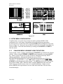
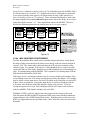
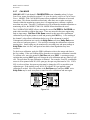
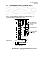
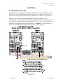
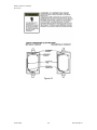
Figure 2.11
!
•
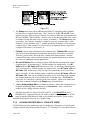
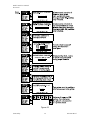
The Group menu entry offers additional flexibility by controlling which channels
trip this menu’s common alarm relay. The 3 choices are 1-16, 1-8 or 9-16. Some
applications have different types of sensors, or, sensors in different areas connected to
the same MODEL 7800 Controller. In these cases, it may be undesirable for a sensor
on channel 9 to trip the same relay as a sensor on channel 2. The Group menus may
restrict this. For example, channels 1-8 might be set to trip common relay 1 while
channels 9-16 trip common relay 2. Another possibility is channels 1-8 be set to trip
common relay 1 while channels 9-16 trip relays on an optional discrete relay PCB
configured for Alarm 1 (see section 3.2).
•
Failsafe controls relay activation for this common relay. Failsafe ON causes the
relay to de-energize during alarm conditions and energize when there is no alarm.
Thereby, a power failure forces the relay contact to the alarm position. Note the
common Fault relay is always failsafe and may be monitored separately to indicate
loss of power conditions in many applications.
•
A1 and A2 Votes allows creation of logical AND function equations that control
common relay 1 & common relay 2. Default settings for common relay 1 are A1
Votes = 01 and A2 Votes = 00 which causes relay 1 to trip if any channel has an
A1 level alarm active. Default settings for common relay 2 are A1 Votes = 00 and
A2 Votes = 01 which causes relay 2 to trip if any channel has an A2 level alarm
active. Example: If either default setting is modified such that A1 Votes = 02 and
A2 Votes = 01, then any two channels must have an A1 level alarm active and any
one channel must have an A2 level alarm active to trip that relay. REMEMBER!
One of the A1’s and the A2 could be on the same channel. These level alarms must
come from a channel included in the Group entry described above.
•
Turning Acknowledge ON (not available on Alarm 1) allows the common relay to
be deactivated during alarm conditions by an Alarm Reset. This is useful if an
audible device is being driven by the relay.
All relays are rated at 5 Amp for 28 VDC and 250 ~VAC RESISTIVE loads.
IMPORTANT: Appropriate diode (DC loads) or MOV (AC loads) snubber devices
must be installed with inductive loads to prevent RFI noise spikes. Relay wiring
should be kept separate from low level signal wiring.
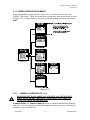
2.3.2 093-0269 DISCRETE RELAY “FAILSAFE” MODE
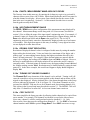
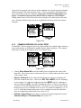
093-0269 Discrete relay options may also be configured to function in a Failsafe mode
using the System Setup menu shown in Figure 2.12. Entering YES causes these discrete
Scott Safety
16
087-0021 Rev F