1
AlphaEclipse RoadStar Sign
Installation Instructions
(For the most recent update, go to http://www.adaptivedisplays.com/support/eclipse)
40
INSTALLATION CHECKLIST
Done?
#
Description
Reference
1
For a sign using a wireless transceiver, conduct a site survey to determine
where to locate the wireless transceiver that will send messages to the sign.
Contact Adaptive Technical Support.
2
Assemble multiple sections.
“Sign sections” on page 9.
“Identifier label” on page 12
3
Mount the sign sections to a superstructure able to withstand live loads and
comply with all national and local codes.
“Mechanical installation” on page 14.
4
Connect the cabling and wiring between each section.
“Multiple section sign assembly and wiring”
on page 16.
5
Determine sign-to-sign connection method to be used (multiple sign
installation only):
Master/Secondary Master
Master/Slave
“Sign-to-sign connections” on page 25.
“Serial address of a sign” on page 34.
6
Connect sign-to-sign communication wire (multiple sign installation only).
“Sign-to-sign connections” on page 25.
7
Determine sign-to-computer connection method to be used:
Wired (RS485): sign serial address _____________
Modem: sign serial address _____________
Wireless transceiver: sign serial address _____________
Fiber optic cable: sign serial address _____________
“Computer-to-sign connections” on
page 28.
8
For a sign using a wired (RS485) or a fiber optic cable, connect sign-tocomputer communication wire.
“Computer-to-sign connections” on
page 28.
9
Install temperature probe (optional).
“Temperature probe mounting (optional)”
on page 19.
10
Connect power and ground to the sign.
“Electrical installation” on page 21.
© Copyright 2005 Adaptive Micro Systems LLC. All rights reserved.
Adaptive Micro Systems • 7840 North 86th Street • Milwaukee, WI 53224 USA • 414-357-2020 • 414-357-2029 (fax) • http://www.adaptivedisplays.com
Trademarked names appear throughout this document. Rather than list the names and entities that own the trademarks or insert a trademark symbol with each mention of the trademarked
name, the publisher states that it is using names for editorial purposes and to the benefit of the trademark owner with no intention of improperly using the trademark.
The following are trademarks of Adaptive Micro Systems: Adaptive, Alpha, AlphaLert, AlphaNET, AlphaNet plus, AlphaEclipse, AlphaEclipse RoadStar, AlphaPremiere, AlphaTicker,
AlphaVision, AlphaVision InfoTracker, Automode, BetaBrite, BetaBrite Director, BetaBrite Messaging Software, Big Dot, Director, EZ KEY II, EZ95, PagerNET, PPD, PrintPak, Serial Clock,
Smart Alec, Solar, TimeNet.
The distinctive trade dress of this product is a trademark claimed by Adaptive Micro Systems LLC.
Due to continuing product innovation, specifications in this manual are subject to change without notice.
March 11, 2005
9717-5001
March 11, 2005
AlphaEclipse RoadStar Sign Installation Instructions (9717-5001)
Contents
Introduction . . . . . . . . . . . . . . . . . . . . . . . . . . . . . . . . . . . . . . . . . . . . . . . . . . . . . . . . . . . . . . . . . . . . . . 4
Revision history . . . . . . . . . . . . . . . . . . . . . . . . . . . . . . . . . . . . . . . . . . . . . . . . . . . . . . . . . . . . . . . . . . . . . . . . . . . . . . . .4
Related documentation . . . . . . . . . . . . . . . . . . . . . . . . . . . . . . . . . . . . . . . . . . . . . . . . . . . . . . . . . . . . . . . . . . . . . . . . . .4
Safety. . . . . . . . . . . . . . . . . . . . . . . . . . . . . . . . . . . . . . . . . . . . . . . . . . . . . . . . . . . . . . . . . . . . . . . . . . . 5
Warnings and cautions . . . . . . . . . . . . . . . . . . . . . . . . . . . . . . . . . . . . . . . . . . . . . . . . . . . . . . . . . . . . . . . . . . . . . . . . . .5
Battery backup . . . . . . . . . . . . . . . . . . . . . . . . . . . . . . . . . . . . . . . . . . . . . . . . . . . . . . . . . . . . . . . . . . . . . . . . . . . . . . . . .5
Equipment . . . . . . . . . . . . . . . . . . . . . . . . . . . . . . . . . . . . . . . . . . . . . . . . . . . . . . . . . . . . . . . . . . . . . . . 6
Description . . . . . . . . . . . . . . . . . . . . . . . . . . . . . . . . . . . . . . . . . . . . . . . . . . . . . . . . . . . . . . . . . . . . . . . . . . . . . . . . . . .6
Top and front views. . . . . . . . . . . . . . . . . . . . . . . . . . . . . . . . . . . . . . . . . . . . . . . . . . . . . . . . . . . . . . . . . . . . . . . . .6
Back, side, and bottom views . . . . . . . . . . . . . . . . . . . . . . . . . . . . . . . . . . . . . . . . . . . . . . . . . . . . . . . . . . . . . . . . .7
Internal view . . . . . . . . . . . . . . . . . . . . . . . . . . . . . . . . . . . . . . . . . . . . . . . . . . . . . . . . . . . . . . . . . . . . . . . . . . . . . .8
Sign sections . . . . . . . . . . . . . . . . . . . . . . . . . . . . . . . . . . . . . . . . . . . . . . . . . . . . . . . . . . . . . . . . . . . . . . . . . . . . . . . . . .9
Equipment identification . . . . . . . . . . . . . . . . . . . . . . . . . . . . . . . . . . . . . . . . . . . . . . . . . . . . . . . . . . . . . . . . . . . . . . . .10
Section label . . . . . . . . . . . . . . . . . . . . . . . . . . . . . . . . . . . . . . . . . . . . . . . . . . . . . . . . . . . . . . . . . . . . . . . . . . . . .10
Sign label . . . . . . . . . . . . . . . . . . . . . . . . . . . . . . . . . . . . . . . . . . . . . . . . . . . . . . . . . . . . . . . . . . . . . . . . . . . . . . .11
Identifier label . . . . . . . . . . . . . . . . . . . . . . . . . . . . . . . . . . . . . . . . . . . . . . . . . . . . . . . . . . . . . . . . . . . . . . . . . . . .12
Temperature protection . . . . . . . . . . . . . . . . . . . . . . . . . . . . . . . . . . . . . . . . . . . . . . . . . . . . . . . . . . . . . . . . . . . . . . . . .13
Equipment symbols . . . . . . . . . . . . . . . . . . . . . . . . . . . . . . . . . . . . . . . . . . . . . . . . . . . . . . . . . . . . . . . . . . . . . . . . . . . .13
Preventing electrostatic discharge damage . . . . . . . . . . . . . . . . . . . . . . . . . . . . . . . . . . . . . . . . . . . . . . . . . . . . . . . . . .13
EMI compliance . . . . . . . . . . . . . . . . . . . . . . . . . . . . . . . . . . . . . . . . . . . . . . . . . . . . . . . . . . . . . . . . . . . . . . . . . . . . . . .13
Installation . . . . . . . . . . . . . . . . . . . . . . . . . . . . . . . . . . . . . . . . . . . . . . . . . . . . . . . . . . . . . . . . . . . . . . 14
Mechanical installation. . . . . . . . . . . . . . . . . . . . . . . . . . . . . . . . . . . . . . . . . . . . . . . . . . . . . . . . . . . . . . . . . . . . . . . . . .14
Overview . . . . . . . . . . . . . . . . . . . . . . . . . . . . . . . . . . . . . . . . . . . . . . . . . . . . . . . . . . . . . . . . . . . . . . . . . . . . . . . .14
Support structure design. . . . . . . . . . . . . . . . . . . . . . . . . . . . . . . . . . . . . . . . . . . . . . . . . . . . . . . . . . . . . . . . . . . .14
Ventilation requirements . . . . . . . . . . . . . . . . . . . . . . . . . . . . . . . . . . . . . . . . . . . . . . . . . . . . . . . . . . . . . . . . . . . .14
Lifting the sign . . . . . . . . . . . . . . . . . . . . . . . . . . . . . . . . . . . . . . . . . . . . . . . . . . . . . . . . . . . . . . . . . . . . . . . . . . .15
Multiple section sign assembly and wiring . . . . . . . . . . . . . . . . . . . . . . . . . . . . . . . . . . . . . . . . . . . . . . . . . . . . . .16
Temperature probe mounting (optional) . . . . . . . . . . . . . . . . . . . . . . . . . . . . . . . . . . . . . . . . . . . . . . . . . . . . . . . .19
Electrical installation . . . . . . . . . . . . . . . . . . . . . . . . . . . . . . . . . . . . . . . . . . . . . . . . . . . . . . . . . . . . . . . . . . . . . . . . . . .21
Guidelines for electrical installation. . . . . . . . . . . . . . . . . . . . . . . . . . . . . . . . . . . . . . . . . . . . . . . . . . . . . . . . . . . .21
Run power to the sign . . . . . . . . . . . . . . . . . . . . . . . . . . . . . . . . . . . . . . . . . . . . . . . . . . . . . . . . . . . . . . . . . . . . . .21
Ground the sign. . . . . . . . . . . . . . . . . . . . . . . . . . . . . . . . . . . . . . . . . . . . . . . . . . . . . . . . . . . . . . . . . . . . . . . . . . .22
2
Contents
AlphaEclipse RoadStar Sign Installation Instructions (9717-5001)
March 11, 2005
Networking . . . . . . . . . . . . . . . . . . . . . . . . . . . . . . . . . . . . . . . . . . . . . . . . . . . . . . . . . . . . . . . . . . . . . 25
Sign-to-sign connections. . . . . . . . . . . . . . . . . . . . . . . . . . . . . . . . . . . . . . . . . . . . . . . . . . . . . . . . . . . . . . . . . . . . . . . .25
Master/Secondary Master sign wiring. . . . . . . . . . . . . . . . . . . . . . . . . . . . . . . . . . . . . . . . . . . . . . . . . . . . . . . . . .26
Master/Slave sign wiring . . . . . . . . . . . . . . . . . . . . . . . . . . . . . . . . . . . . . . . . . . . . . . . . . . . . . . . . . . . . . . . . . . . .27
Computer-to-sign connections . . . . . . . . . . . . . . . . . . . . . . . . . . . . . . . . . . . . . . . . . . . . . . . . . . . . . . . . . . . . . . . . . . .28
RS485 wire computer-to-sign connection. . . . . . . . . . . . . . . . . . . . . . . . . . . . . . . . . . . . . . . . . . . . . . . . . . . . . . .29
Modem computer-to-sign connection . . . . . . . . . . . . . . . . . . . . . . . . . . . . . . . . . . . . . . . . . . . . . . . . . . . . . . . . . .30
Fiber optic computer-to-sign connection . . . . . . . . . . . . . . . . . . . . . . . . . . . . . . . . . . . . . . . . . . . . . . . . . . . . . . .31
Wireless transceiver computer-to-sign connection (Locus) . . . . . . . . . . . . . . . . . . . . . . . . . . . . . . . . . . . . . . . . .32
Wireless transceiver computer-to-sign connection (Alpha RF900) . . . . . . . . . . . . . . . . . . . . . . . . . . . . . . . . . . . .33
Appendix . . . . . . . . . . . . . . . . . . . . . . . . . . . . . . . . . . . . . . . . . . . . . . . . . . . . . . . . . . . . . . . . . . . . . . . 34
Serial address of a sign . . . . . . . . . . . . . . . . . . . . . . . . . . . . . . . . . . . . . . . . . . . . . . . . . . . . . . . . . . . . . . . . . . . . . . . . .34
How to open a section door . . . . . . . . . . . . . . . . . . . . . . . . . . . . . . . . . . . . . . . . . . . . . . . . . . . . . . . . . . . . . . . . . . . . . .35
How to remove a section door . . . . . . . . . . . . . . . . . . . . . . . . . . . . . . . . . . . . . . . . . . . . . . . . . . . . . . . . . . . . . . . . . . . .36
Assembly drawings . . . . . . . . . . . . . . . . . . . . . . . . . . . . . . . . . . . . . . . . . . . . . . . . . . . . . . . . . . . . . . . . . . . . . . . . . . . .38
Technical specifications . . . . . . . . . . . . . . . . . . . . . . . . . . . . . . . . . . . . . . . . . . . . . . . . . . . . . . . . . . . . . . . . . . . . . . . . .42
Contents
3
March 11, 2005
AlphaEclipse RoadStar Sign Installation Instructions (9717-5001)
Introduction
Revision history
Revision
Date
9717-5001
March 11, 2005
Notes
First release.
Related documentation
Part #
9708-8081
4
Manual title
AlphaNET Version 3.0 User Manual
Description
Explains the software used to create and send
messages to the sign.
Introduction
AlphaEclipse RoadStar Sign Installation Instructions (9717-5001)
March 11, 2005
Safety
Warnings and cautions
WARNING
Hazardous voltage.
Contact with high voltage
may cause death or serious
injury.
Always disconnect power to
unit prior to servicing. SM1000A
Other warnings and cautions are posted in appropriate locations throughout this manual.
Battery backup
In the event of power loss, backup batteries in an AlphaEclipse RoadStar sign provide power in order to
maintain time.
A backup battery is located on the top of a sign’s controller board under the daughter card (see below). The
backup battery should only be replaced by a qualified Adaptive technician:
Backup battery
(located underneath
the daughter card)
Daughter card
Controller board
WARNING
Danger of explosion if battery is
incorrectly replaced. Replace only
with the same or equivalent type
recommended by the manufacturer.
Dispose of used batteries according
to the manufacturer's instructions.
SM1019A-En
AVERTISSEMENT
WARNUNG
SM1019A-Fr
AVVERTENZA
ADVERTENCIA
SM1019A-It
Safety
SM1019A-Ge
SM1019A-Sp
5
March 11, 2005
AlphaEclipse RoadStar Sign Installation Instructions (9717-5001)
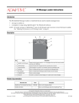
Equipment overview
Description
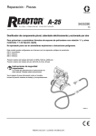
Top and front views
Shown below is a 16 x 48 (row x column) sign. Other sign sizes are similar.
Top view
B
Front view
A
C
See “Assembly drawings” on page 38 for additional information.
Item
Name
Description
Each cube has two doors, each with 16 louvered display boards. (Note that one-line sign cubes will only
have 14 louvered display boards.)
The group of display boards on each cube door
is 8 pixels tall by 8 pixels wide. (7 pixels tall by 8
pixels wide on a one-line sign.)
A
Cube
A single
LED pixel.
Doors
(both open)
6
Each display board is 4 pixels wide.
B
Lifting hardware
Used to lift the sign during installation. This hardware must be removed after the sign is installed or
corrosion to the sign may occur.
C
Light sensor hole
Allows light into the light sensor. This opening must be kept free of obstructions. The location of the light
sensor may vary depending on the pitch (distance between pixels) of the sign. Shown above are the two
possible locations.
Equipment overview
AlphaEclipse RoadStar Sign Installation Instructions (9717-5001)
March 11, 2005
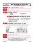
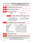
Back, side, and bottom views
Shown below is a 16 x 48 (row x column) sign. Other sign sizes are similar.
Back view
Left side
Right side
F
G
E
D
C
B
A
Bottom view
See “Assembly drawings” on page 38 for additional information.
Item
Name
Description
Each section is attached to a support frame:
A
Section support frame
B
Communications conduit
holes
7/8-inch conduit holes for communication wires. (Remove hole plugs prior to use.)
C
Power conduit hole
7/8-inch conduit hole for power wires. (Remove hole plugs prior to use.)
D
Ground lug
Grounding point for earth ground. See “Ground the sign” on page 22.
E
Equipment labels
Section label, sign label, identifier label, and serial address label containing information about the sign.
Sign sections will contain one or more of these labels depending on whether the section is a main or a
secondary section. See “Equipment identification” on page 10.
F
Lifting hardware
Used to lift the sign during installation. This hardware must be removed after the sign is installed or
corrosion to the sign may occur.
G
Wireway connection
holes
Used to route power and communication wires between each LED module.
Equipment overview
7
March 11, 2005
AlphaEclipse RoadStar Sign Installation Instructions (9717-5001)
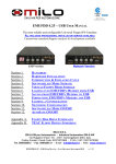
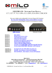
Internal view
Shown below is a 16 x 48 (row x column) sign. Other sign sizes are similar.
See “Assembly
drawings” on
page 38 for
additional
information.
Ordinary
Cube
Ordinary
Cube
Ordinary
Cube
Ordinary
Cube
Ordinary
Cube
Control
Cube
A
B
Item
Name
Description
Power and communication wires are routed to all the sections from the control cube. There is one control cube
in a sign and it is located at the bottom right side of the main section (see “Sign sections” on page 9). The
control cube contains the controller plate (see below):
NOTE: Signs configured as Master
contain the controller board and
communication options.
A
Regulator board
Controller plate
Control cube
Controller board
Power switches
Power terminal
block
Sign doors
Wiring terminal block
Surge suppressor board
Ordinary cubes are found in all secondary sections (see “Sign sections” on page 9) and in all main sections
except the very bottom right cube (this is the control cube). The parts inside an ordinary cube can be accessed
by opening the front of the cube (see “How to open a section door” on page 35):
B
Ordinary cube
Cooling fan
(See “Technical
specifications” on
page 42 as the
number of fans
vary.)
Power supply
WARNING
Burn hazard.
Hot surface.
Do not touch.
SM1006B
LED driver board
(back)
8
Open a sign door slowly to prevent
damage to internal components.
Equipment overview
AlphaEclipse RoadStar Sign Installation Instructions (9717-5001)
March 11, 2005
Sign sections
All sign sizes are made up of one or more building blocks, called sections. The right-most section is always the
main section (1 of X number of sections); all others are secondary sections.
Small building block
• two cubes
• 7 rows by 32 columns
One-line signs
7 x 32 section
Large building block
• three cubes
• 7 rows by 48 columns
7 x 48 section
For example, a 7 x 80 one-line sign is made up of one 7-row, 32-column building block and one 7-row, 48-column building block:
SECONDARY section
7 x 32 section (2 of 2 sections)
MAIN section
Note: The main section must
always be on the far right, as
viewed from the front of the sign.
7 x 48 section (1 of 2 sections)
8 x 32 section
Two-line signs
Small building block
• four cubes
• 16 rows by 32 columns
8 x 32 section
8 x 48 section
Large building block
• six cubes
• 16 rows by 48 columns
8 x 48 section
For example, a 16 x 80 two-line sign is made up of one 16-row, 32-column building block and one 16-row, 48-column building block:
SECONDARY section
16 x 32 section (2 of 2 sections)
Equipment overview
MAIN section
Note: The main section must
always be on the far right, as
viewed from the front of the
sign.
16 x 48 section (1 of 2 sections)
9
March 11, 2005
AlphaEclipse RoadStar Sign Installation Instructions (9717-5001)
Equipment identification
Section label
Section labels are located on the back of each sign section. See “Sign sections” on page 9.
A
B
C
Item
Name
Description
Identification number for the section:
1175-8901MX0732RED
LED lamp color:
• RED = Red
• AMB = Amber
Number of pixel columns
Number of pixel rows
A
Section configuration
• MX = Main Section
• SX = Secondary Section
• MS = Main Secondary
Section model number
Angle of visibility:
• 00 = 30°
• 01 = 70°
Pitch (mm)
AlphaEclipse RoadStar
Series Sections
10
B
Series letter
Revision level of sign.
C
Date of manufacture
Month, day, and year the sign was made.
Equipment overview
AlphaEclipse RoadStar Sign Installation Instructions (9717-5001)
March 11, 2005
Sign label
Sign labels are located on each main section, one on the outside and one on the inside. See “Sign sections” on
page 9.
A
B
C
D
Item
Name
Description
Identification number for the assembled sign:
RS8901-16x160-RED
LED lamp color:
• RED = red
• AMB = Amber
Number of pixel columns
A
Sign model number
Number of pixel rows
Angle of visibility:
• 00 = 30°
• 01 = 70°
Pitch (mm)
Product name
(AlphaEclipse RoadStar)
B
Serial number
Consecutive, unique identification number for the sign.
C
Series letter
Revision level of sign.
D
Electrical information
Input voltage, frequency, and total amperage of sign.
Equipment overview
11
March 11, 2005
AlphaEclipse RoadStar Sign Installation Instructions (9717-5001)
Identifier label
Identifier labels are located on the back of each sign section near the section label. See “Sign sections” on
page 9.
A
B
C
Item
12
Name
Description
A
Serial number
Consecutive, unique identification number for the sign (see sign label), plus a letter suffix that
indicates assembly location of sign.
B
Serial number barcode
The serial number expressed as a barcode.
C
Section number
Indicates assembly location of section.
Equipment overview
AlphaEclipse RoadStar Sign Installation Instructions (9717-5001)
March 11, 2005
Temperature protection
If the temperature inside of the left-most or right-most cube exceeds 100°F (+/- 7°F) or 38°C (+/- 4°C), the
cube’s fans will start. When the temperature falls below 80°F (+/- 10°F) or 27°C (+/- 6°C), the fans will stop.
The fans do not draw in outside air. They are used for recirculating air within the sign cubes.
If the power supply ambient temperature reaches 194°F (+/- 9°F) or 90°C (+/- 5°C), the power supply will shut
down.
Equipment symbols
Chassis ground
Power (I = On, 0 = Off)
Preventing electrostatic discharge damage
ATTENTION
OBSERVE PRECAUTIONS
ELECTROSTATIC
SENSITIVE DEVICE
This equipment contains components that may be damaged by “static electricity”, or electrostatic discharge.
To prevent this from happening, be sure to follow the guidelines in Adaptive Tech Memo 00-0005, “Preventing
Electrostatic Discharge (ESD) Damage,” available on our Web site at http://www.adaptivedisplays.com.
EMI compliance
This equipment has been tested and found to comply with the limits for a Class A digital device, pursuant to
Part 15 of the FCC Rules. These limits are designed to provide reasonable protection against harmful interference
when the equipment is operated in a commercial environment.
This equipment generates, uses, and can radiate radio frequency energy and, if not installed and used in
accordance with installation guidelines, may cause harmful interference to radio communications. Operation of
this equipment in a residential area is likely to cause harmful interference, in which case the user will be required
to correct the interference at his own expense.
Equipment overview
13
March 11, 2005
AlphaEclipse RoadStar Sign Installation Instructions (9717-5001)
Installation
NOTE: See “Multiple section sign assembly and wiring” on page 16 for specific information on sign assembly
and wiring.
Mechanical installation
Overview
Because every sign installation is unique, there is no single procedure for mounting AlphaEclipse RoadStar
signs. However, sign sections must be supported (affixed to superstructure able to withstand live loads and comply with all
national and local codes) prior to assembling the sections or opening the doors, otherwise sign may tip causing serious injury.
Additionally, sign parts could sustain damage if the doors are opened and the sign is not fully off the ground. Failure to
comply will void the sign’s warranty.
This section is only intended as a guide.
All installations, superstructure designs, and connections must be designed and approved by a
qualified structural engineer. Call Adaptive Micro Systems at 1-800-558-7022 for contact information
for structural engineering consultants.
•
Drill holes as needed in the sign’s steel framework for fasteners. Drilling holes in any of the excluded areas will
void the sign’s warranty. When drilling holes, follow these guidelines:
–
–
•
Connections must be analyzed by a structural engineer.
Dissimilar metals must be isolated to avoid galvanic corrosion.
Any area on the sign’s frame that had paint removed during mounting must be recoated with paint that is
UL recognized to standard UL-1332, category DTOV2. Failure to repaint the area will result in accelerated
corrosion of the sign’s structure. Adaptive Micro Systems is not responsible for any failure in the sign’s structure
because of this. Failure to comply will void the sign’s warranty.
Support structure design
The design of a sign’s support structure depends on a number of factors:
•
mounting methods
•
building codes
•
foundation
•
sign size
•
sign weight
•
sign height
•
wind loading
•
seismic loading
Ventilation requirements
If the sign is mounted to a solid surface like a wall, then nothing must block the space between the top, bottom,
and sides of the sign and the solid surface. Allow 6-inches of space (minimum) between the sign and any solid
surface.
To avoid heat build-up and depending on sign size, allow more space at the back of the sign to provide ample
air flow. Fans can be used to supplement natural air flow. Shading the back of the sign will enhance thermal
performance.
14
Installation
AlphaEclipse RoadStar Sign Installation Instructions (9717-5001)
March 11, 2005
Lifting the sign
Use a lifting bar adjusted to the width of the lifting hardware on the sign to raise the sections. After mounting
the sign sections, remove the lifting hardware or corrosion to the sign may occur.
NOTE: Sign sections must be supported (affixed to superstructure able to withstand live loads and comply with all
national and local codes) prior to assembling the sections or opening the doors, otherwise sign may tip causing
serious injury.
WARNING
Crush hazard.
Do not lift sign
with more than a
15 degree tilt.
SM1020
WARNING
WARNING
Possible crush hazard.
Always use lifting bar
to lift the sign. Otherwise
eyebolts may break and
sign may fall, causing
serious injury or death.
Possible crush hazard.
Always use eyebolts to lift
sign. Otherwise the sign
may fall, causing serious
injury or death.
SM1017
SM1015
45°
maximum
Lifting bar
RECOMMENDED
Installation
45°
maximum
Lifting hardware
NOT RECOMMENDED
15
March 11, 2005
AlphaEclipse RoadStar Sign Installation Instructions (9717-5001)
Multiple section sign assembly and wiring
Large AlphaEclipse RoadStar signs are shipped from the factory in multiple sections.
Multiple section signs are assembled as follows:
NOTE: Always begin numbering from the section with the control cube to the left, as viewed from the front of the sign.
See “Identifier label” on page 12 for more information.
Example of a one-line, 7 x 160 size sign:
Section 4 of 4
(7 x 32)
Section 3 of 4
(7 x 32)
Section 2 of 4
(7 x 48)
Section 1 of 4
(7 x 48)
Section 2 of 4
(16 x 48)
Section 1 of 4
(16 x 48)
Control
cube
Example of a two-line, 16 x 160 size sign:
Section 4 of 4
(16 x 32)
Section 3 of 4
(16 x 32)
Control
cube
1.
Prior to mounting each section to a superstructure able to support the sign section weights, read the
identifier label on each sign section to determine section location. See “Identifier label” on page 12. Make
sure the sign sections are mounted flush and level with one another.
2.
Remove power from the sign. See “Internal view” on page 8 for location of the power switches. Note that
on a two-line sign, both switches must be in the off position to remove power from the sign.
WARNING
Hazardous voltage.
Contact with high voltage
may cause death or serious
injury.
Always disconnect power to
unit prior to servicing. SM1000A
3.
Open the sign sections. See “How to open a section door” on page 35.
4.
Remove the stickers covering the wireway connection holes.
Wireway connection holes
16
Installation
AlphaEclipse RoadStar Sign Installation Instructions (9717-5001)
5.
March 11, 2005
Starting with the left-most section, unclip the twist lock securing the AC wire harness. Thread the AC wire
harness through the top wireway connection hole on the right and snap it into the next section’s wireway
harness. Repeat for all sections as necessary:
AC wire harness
Twist lock
Thread AC wire harness through top
conduit hole on right and into next
section.
AC wire harness snaps
6.
Affix the grommet to the top wireway connection hole.
Grommet
7.
Starting with the left-most section, unclip the twist lock securing the communication cable. Thread the
communication cable (red-lined edge up) through the bottom wireway connection hole on the right and
attach it to the next section’s LED driver board. Repeat for all sections as necessary:
Thread cable through bottom conduit
hole on right and into next section.
LED driver board
Twist lock
Communication cable
Installation
17
March 11, 2005
8.
AlphaEclipse RoadStar Sign Installation Instructions (9717-5001)
Affix the grommet to the bottom wireway connection hole.
Grommet
9.
Starting with the left-most section, thread the ground wire through the bottom wireway connection hole on
the right and snap it into the next section’s ground wire. Repeat for all sections.
Thread the ground wire through
bottom conduit hole on right and into
next section.
Ground wires
18
Installation
AlphaEclipse RoadStar Sign Installation Instructions (9717-5001)
March 11, 2005
Temperature probe mounting (optional)
When properly installed, the temperature probe will indicate accurate temperature. The best location for the
temperature probe is on the display or the display structure.
NOTE: Using the supplied 25-foot temperature probe cable (pn 7122-0401, 22 AWG), there is a maximum
distance of 250 feet between the temperature probe and the sign. However, you can extend distance
and potentially find a better mounting location by changing the cable gauge. Contact Technical
Support for more information.
For two or more signs connected as Master/Secondary Master or Master/Slave, the temperature probe can be
connected to either sign.
Do
•
Choose a location with the following criteria:
–
–
–
–
Air movement is not restricted by nearby walls or other obstructions.
The mounting background is light-colored and not dark-colored.
The location is above vegetation and not above asphalt or blacktop.
The location is on the north side of a building to provide protection from the sun.
•
Shield the probe from the effect of the direct sun, reflected heat, or any nearby sources of heat, such as
chimneys, lamps, vents, or HVAC ducts.
•
If the temperature probe will be mounted to a heat-conducting surface, like metal, prevent the
temperature probe’s case from conducting heat from this surface by placing a non-heat conducting
material, like a wood board, between the surface and the probe.
•
Mount the temperature probe at least 6 feet off the ground.
•
Mount the temperature probe at least one foot below the eave of a protected overhang so convection
currents (rising hot air flow) are not trapped around the temperature probe. Also, make sure convection
currents are not blocked by the mounting plates.
•
Mount the probe so that the vents face downward.
•
Hand-tighten the mounting screws so as not to strip them.
Do not
•
Mount the temperature probe along the top of the sign.
•
Mount the temperature probe near sprinklers and water fountains.
•
Run the temperature probe cable and the sign’s power wires through the same conduit.
Installation
19
March 11, 2005
AlphaEclipse RoadStar Sign Installation Instructions (9717-5001)
Installation
1.
Mount the temperature probe with the vents pointing downward using the mounting holes OR the
conduit holes on the bracket.
2.
Run the temperature probe to the appropriate terminal block in the control cube.
NOTE: The temperature probe cable and the sign’s power wires must be run in different conduits.
Connect the temperature probe cable to the wireway terminal block as shown below.
SHIELD
RS485A (+)
RS485B (-)
TERMINATION
GND
+ 5VDC
3.
Wiring terminal block
(on controller plate)
White
Green
Red
Black
Bare wire
1 2 3 4 5 6 7
Conduit holes
Mount the temperature
probe so that the vents
point downward
Mounting holes
(circled)
Temperature probe
20
Installation
AlphaEclipse RoadStar Sign Installation Instructions (9717-5001)
March 11, 2005
Electrical installation
Electrical installation must only be attempted by a qualified electrician. Electrical connection must comply
with all applicable national and local codes.
WARNING
Hazardous voltage.
Contact with high voltage
may cause death or serious
injury.
Always disconnect power to
unit prior to servicing. SM1000A
WARNING
Disconnect main
power before
servicing!
Each section's power switch
controls that section only!
Guidelines for electrical installation
•
On a two-line sign, both power switches must be in the off position to remove power from the sign. See
“Internal view” on page 8 for location of the power switches.
•
Inspect all internal sign cabling for proper connection and seating.
•
All power wiring must be from circuit breaker-protected lines.
•
A two-pole disconnect device must be installed in the building wiring for each branch circuit supplying
the sign.
•
The sign must be properly grounded according to the applicable codes (for example, NEC Article 250 and
600, and IEEE 1100-1999).
•
Run separate conduits for signal wires (for example, RS232, RS485) and for power wires. However, fiber
optic wire may be run in the same conduit with power wires.
•
All electrical connections must be watertight.
•
Use minimum 80° C copper wire only.
Utiliser uniquement un fil en cuivre pouvant supporter 80° C minimum.
•
Torque terminals to a minimum of 7 in/lbs and a maximum of 10 in/lbs.
Serrer les bornes à 0,79 N/m minimum, mais pas à plus de 1,13 N/m.
Run power to the sign
1.
Run power to the sign using waterproof conduit.
•
•
•
•
•
•
Installation
DO drill holes for power entry at the back of the control cube where indicated by a label.
DO NOT drill additional conduit holes in the right side of the sign. The wiring will interfere with the
door hinge.
DO NOT drill additional conduit holes through the controller plate in the control cube.
DO NOT drill additional conduit holes along the bottom of the cube, note that water may pool there.
DO NOT route power and communication wires out of the cube door and around the side of the sign;
the wires will be damaged when the door is closed.
DO NOT route power and communication wires in the same conduit (unless the communication wires
are fiber optic).
21
March 11, 2005
AlphaEclipse RoadStar Sign Installation Instructions (9717-5001)
Adaptive Explains
Why is it necessary to always run two conduits to a sign?
It is not always necessary. Two conduits are only necessary when communication wire, like RS485 wire, is run to a sign
from a computer or from another sign. In these cases, one conduit would contain the sign’s power wires and the other conduit
the communication wires.
If power and communication wires are put in the same conduit, there is a chance the communication wires might pick up
electrical interference from the power wires. For example, when a live power cord is placed next to a stereo speaker wire, the
interference from this cord may cause the speaker to hum. In the case of a sign, this same effect could disrupt messages sent to
the display.
On the other hand, fiber optic cable and power wires can share the same conduit because fiber optic cable is immune to
electrical interference.
2.
Connect each power circuit to the appropriate wireway power terminal on the controller plate (example
below):
Ground the sign
The sign must be properly grounded in order to provide three types of protection:
•
Ground fault protection (see page 23) — The sign must be wired to provide a permanent, low impedance
pathway to carry sign ground fault current. This is necessary in order to quickly clear a sign ground fault
by opening the power circuit to the sign.
Earth grounding a sign through some type of ground rod bonded to the sign is not sufficient ground fault protection.
•
Lightning strike protection (see page 24) — A sign must be earth grounded either through an existing
ground rod or separate ground rod(s) bonded to the sign (see NEC article 250.32).
•
Electronic equipment protection (see page 24) — An improperly wired sign could radiate electromagnetic
fields (EMF) that may damage or interfere with electronic equipment in or near the sign (see NEC Article
250.6).
Connect to earthground rod.
One of the wireway grounding points
should be connected to earth ground
(for example, a grounding rod).
Signs are equipped with a ground lug
on the back of the main section.
Outside sign
22
Inside sign
Installation
AlphaEclipse RoadStar Sign Installation Instructions (9717-5001)
March 11, 2005
Ground fault protection
Sign with Ground Fault Protection
= ground fault current path
Service
Panel
Sign
A “ground fault” protected circuit is
different from a “ground fault interrupt”
protected circuit.
A sign should be ground fault protected
as shown.
However, a sign should not be
connected to a ground fault interrupt
(GFI) protected circuit.
N
Lightning
electrode
Ground fault
N
Because a low resistance pathway has been provided,
the large amount of current that flows along this pathway
will cause a breaker to trip and the circuit to open.
Lightning
electrode
Sign without Ground Fault Protection
= ground fault current path
Panel
Service
Sign
N
N
Ground fault
No ground
connection
No path for fault current
Lightning
electrode
Because of the relatively high resistance of an earth ground,
only a small amount of current will flow through the lightning electrode.
This small current flow will probably not be enough to open the circuit.
As a result, the sign case will become a shock hazard
and possibly a fire hazard if the current level is high enough.
Lightning
electrode
Adaptive Explains
What is a ground fault?
It’s when a “hot” wire unintentionally makes contact with metal, like an electrical outlet box or the case of a sign. If a sign is wired
properly, a circuit breaker will trip (or “open”) because too much electrical current is flowing. The ground fault will have to be corrected
before the circuit breaker can be closed.
How do you protect against ground faults?
Provide a ground fault current path with so little resistance (basically just the resistance of the power wires) that a huge amount of
current tries to flow. For example, imagine a sign is powered by 120V and is connected to a 20 ampere circuit. If this sign tries to draw
more than 20 amps of current, the circuit breaker will trip and the circuit will open. Let’s say that this sign is 300 feet away from its power
source and that the total resistance of this wire is 0.4 ohms. Using Ohm’s Law, the fault current = 120V divided by 0.4 ohms = 300 amps!
This amount of current will cause the circuit breaker to open very quickly — removing the shock threat.
Why can’t lightning rods be used to protect against ground faults?
A lightning rod (or earth ground) may have too much resistance and so not enough current will flow through it to cause a circuit
breaker to open. For example, imagine an earth ground has a resistance of 10 ohms, which is low. Using Ohm’s Law again, the fault
current = 120V divided by 10 ohms = 12 amps. This is not enough current to cause the 20 amp circuit breaker to open. This means the
ground fault would not be cleared and dangerous levels of current would be present on the sign’s case and near the ground rod itself.
Installation
23
March 11, 2005
AlphaEclipse RoadStar Sign Installation Instructions (9717-5001)
Lightning strike protection
A sign bonded to an earth ground has a means of dissipating the high voltage and current from a lightning
strike. The resistance of the grounding electrode must be as low as possible. However, damage can still occur to a
sign’s electronic equipment from lightning voltage transients.
Though some surge protection is incorporated into a sign, to protect a sign from high-voltage lightning
transients, surge protectors need to be installed at the panelboards (see NEC Article 280 and 284).
Electronic equipment protection
A common cause for the failure of sensitive electronic equipment is the presence of objectionable current (also
called objectionable neutral current) on grounding and bonding paths.
Objectionable neutral current can be caused by:
•
Errors in installation wiring
•
Improper neutral-to-case bonds (illustrated below)
Objectionable Neutral Current caused by Improper Neutral-to-Case Bond
= normal current path
= objectionable neutral current path
Service side
Load side
Service
Panel
Sign
N
Lightning
electrode
•
N
Because of an improper neutral-to-case connection (shown above),
a shock hazard will be created because of potentially hazardous current
flowing on conductive surfaces like the sign's housing.
In addition, this current flow may cause electromagnetic interference
that disrupts the sign's internal electronics.
Lightning
electrode
Equipment-grounding conductor used to carry neutral current — This situation arises when no separate
grounding wire is present when connecting power to a sign. NEC Article 250.32(B)(2) does permit a
neutral-ground bond to be used in a separate structure if all of the following three conditions are met:
(1) an equipment grounding connector is not run with the supply to the structure
(2) there are no continuous metallic paths bonded to the grounding system in both structures involved
(3) equipment ground-fault protection has not been installed on the common AC service
Adaptive does not recommend using the equipment-grounding connector to carry neutral current as permitted by NEC
250.32(B)(2) because it creates a potentially hazardous situation. For example, a future installer might connect cabling
between the two structures and this could create a dangerous parallel current path.
Adaptive Explains
How can you tell if objectionable neutral current is present?
A microohm multimeter can be used to measure the voltage difference between the neutral and ground conductors.
Though a difference of 0V is ideal, the voltage difference should not exceed 0.5V.
24
Installation
AlphaEclipse RoadStar Sign Installation Instructions (9717-5001)
March 11, 2005
Networking
Up to four AlphaEclipse RoadStar signs can be connected together into a network (see “Sign-to-sign
connections” on page 25).
Also, in order to display messages, a sign must be connected to a computer that is running AlphaNET
software (see “Computer-to-sign connections” on page 28).
Sign-to-sign connections
Two or more signs can be set up as either
•
Master/Secondary Master (page 26) — two to four signs that can display a different message. While the
same message could be sent to both signs, the messages may not appear at exactly the same time. Signs
connected as Master/Secondary Master require a temperature probe be connected to just the Master sign
in order to display the temperature on both.
•
Master/Slave signs (page 27) — all these signs display the same message at the same time. In this setup, one
sign is configured as the Master and all the others as Slave signs.
Adaptive Explains
Does it matter if signs are set up as Master/Secondary Master or Master/Slave?
The most important difference between Master/Secondary Master and Master/Slave signs is that Master/Slave signs all
display the same message at the exact same time. On the other hand, signs configured as Master/Secondary Master allow you to
display a different message on each of the signs.
How are signs set up to be Master/Secondary Master or Master/Slave?
Signs are configured at the factory. Master/Secondary Master is normally the factory default.
Is there any way to tell if a sign is a Master, a Secondary Master, or a Slave sign by just looking at it?
Probably not without turning the sign off and then on again. When you do this, the word “Master”, “Sec-Master” or
“Slave” will appear in the sign’s startup messages.
Also, there is a label on the back of the sign that indicates how the sign is configured.
Networking
25
March 11, 2005
AlphaEclipse RoadStar Sign Installation Instructions (9717-5001)
Master/Secondary Master sign wiring
Overview
Signs connected as Master/Secondary Master can each display a unique message, unlike Master/Slave signs
where all signs always display the same message at the same time. In a Master/Secondary Master sign pair, a
message can be displayed on Master sign #1 by sending the message to serial address 1, or displayed on Secondary
Master sign #2 by sending the message to serial address 2. Also, a message can be displayed on all Master signs by
broadcasting the message to serial address 0.
The wiring is connected between each sign’s controller board and the terminal block located on the controller
plate:
The controller board and wiring
terminal block are located on the
controller plate in the control cube.
See “Internal view” on page 8.
Controller board
COM0 RS485/422
Wiring terminal block
Wiring
Master sign #1 – Serial address 1
1 2 34 5
1 2 34 5 67
SHIELD
RS485- (red)
RS485+ (black)
RS485+ (black)
RS485- (red)
SHIELD
W IRE 2
1 2 34 5
Secondary Master sign #2 – Serial address 2
SHIELD
RS485+ (black)
RS485- (red)
COM0 RS485/422
(on controller board)
For 3 or more signs, connect another wire from
here to COM0 RS485/422 in the next sign.
26
Wiring terminal block
(on controller plate)
WIRE 3
WIRE 1
COM0 RS485/422
(on controller board)
1 2 34 5 67
RS485- (red)
RS485+ (black)
SHIELD
Wiring terminal block
(on controller plate)
For 3 or more signs, connect another wire from here
to the wiring terminal block in the next sign.
Networking
AlphaEclipse RoadStar Sign Installation Instructions (9717-5001)
March 11, 2005
Master/Slave sign wiring
Overview
Signs connected as Master/Slave always display the same message at the same time, unlike Master/Secondary
Master signs where unique messages can be displayed on each sign. For Master/Slave signs, all messages should
be sent to either serial address 0 or to all of the sign’s addresses (in the example below, address 1 and 2).
The wiring is connected between each sign’s controller board and the terminal block located on the controller
plate:
The controller board and wiring
terminal block are located on the
controller plate in the control cube.
See “Internal view” on page 8.
Controller board
COM0 RS485/422
COM3 RS485
Wiring terminal block
Wiring
Master sign #1 – Serial address 1
RS485- (red)
SHIELD
RS485- (red)
RS485+ (black)
RS485+ (black)
RS485+ (black)
RS485- (red)
SHIELD
SHIELD
1 2 34 5
WIRE 1
Slave sign #2 – Serial address 2
COM3 RS485
(on controller board)
Wiring terminal block
(on controller plate)
WIRE 2
COM0 RS485/422
(on controller board)
1 2 34 5 67
RS485- (red)
WIRE 3
1 2 34 5
SHIELD
RS485+ (black)
RS485- (red)
RS485+ (black)
RS485- (red)
SHIELD
RS485+ (black)
SHIELD
1 2 34 5
COM0 RS485/422
(on controller board)
For 3 or more signs, connect another wire from
here to COM0 RS485/422 in the next sign.
Networking
1 2 34 5 67
Wiring terminal block
(on controller plate)
For 3 or more signs, connect another wire from here
to the wiring terminal block in the next sign.
1 2 34 5
COM3 RS485
(on controller board)
For 3 or more signs, connect
another wire from here to COM3
RS485 in the next sign.
27
March 11, 2005
AlphaEclipse RoadStar Sign Installation Instructions (9717-5001)
Computer-to-sign connections
In order to display messages, a sign must be connected to a computer that is running AlphaNET software.
(This computer is referred to as the “messaging computer”.)
There are a number of ways to connect the messaging computer to a sign:
•
RS485 wire (page 29) — using RS485 plenum wire (pn 7124-0203), a sign can be wired to a computer that
could be up to 4000 feet away from the sign.
Ordinary wire, phone wire, CAT 5 wire, and so on must NOT be used in place of Adaptive’s
RS485 plenum wire.
28
•
Modem (page 30) — by placing a modem inside a sign (factory installed) and attaching another modem to
the messaging computer, messages are sent to a sign through ordinary phone lines.
•
Fiber optic (page 31) — using a fiber optic mini-modem inside a sign (factory installed) and another minimodem connected to the messaging computer, a sign can be connected to a computer that could be up to 2
miles away from the sign. Fiber optic cable is immune to electrical interference so the cable can be placed
in the same conduit as the power wires.
•
Wireless transceiver (page 32) — for this option, one wireless transceiver is placed inside the sign (called
the “Receive” unit which is factory installed) and another transceiver (called the “Master”) is connected to
the messaging computer. Wireless transceivers can connect to a sign up to 2 miles away. (Actual distance
can vary greatly depending on the local environment, obstructions, electrical interference, and so on.)
Networking
AlphaEclipse RoadStar Sign Installation Instructions (9717-5001)
March 11, 2005
RS485 wire computer-to-sign connection
Overview
In order to display messages on a sign, the messaging computer must be connected to the sign, such as with a
Converter Box III.
AlphaEclipse RoadStar sign
up to 4000 feet
10 feet
RS485 plenum cable
(pn 7124-0203)
RS232 cable
(pn 1088-8634)
Converter Box III
(pn 1088-1111)
Messaging computer running
AlphaNET software
The wiring is connected from the controller board to the converter box:
The controller board is located on the
controller plate in the control cube.
See “Internal view” on page 8.
Controller board
COM0 RS485/422
Wiring
RS485- (red)
RS232 cable (pn 1088-8634)
SHIELD
To messaging computer
RS485+ (black)
Converter Box III (pn 1088-1111)
Move this switch to the
"TERMINATED" position.
SHIELD
RS485+ (black)
RS485- (red)
RS485 plenum cable
(pn 7124-0203)
1 2 34 5
COM0 RS485/422
(on controller board)
Networking
29
March 11, 2005
AlphaEclipse RoadStar Sign Installation Instructions (9717-5001)
Modem computer-to-sign connection
Overview
In order to display messages on a sign, the messaging computer must be connected to the sign, such as with a
pair of telephone modems (a Transmitting modem attached to the messaging computer and a Receiving modem
attached to a sign).
Modems can connect to a sign that is almost anywhere. However, a sign must have its own phone line.
Transmitting modem (pn 1088-9301)
RS232 cable
AlphaEclipse RoadStar sign
(supplied with modem)
Messaging computer
running AlphaNET software
Receiving modem (inside sign) (pn 1088-9301)
The wiring is connected from the controller board and the surge suppressor board to the modem:
COM0 RS232
The controller board is located on the
controller plate in the control cube.
See “Internal view” on page 8.
Note: The surge suppressor board is
also located on the controller plate
immediately to the right of the modem.
Controller board
Wiring
RJ11
phone
cord
Green (TIP)
Red (RING)
RED
RING
}
To
telephone
service
GREEN
TIP
Surge suppressor board
(on controller plate)
Modem DIP switch settings:
ON
1
COM0 RS232
(on controller board)
2
3
4
5
6
7
8
Switch #1 = ON (Modem ignores DTR)
Switch #3 = ON (Display result codes)
Switch #4 = ON (Do not echo offline commands)
Switch #8 = ON (Recognize AT commands)
Modem AT command setup string:
AT&H0&R1&B1&N6&Y0&W0
DB25-to-DB9-Type B RS232 cable
(pn 1088-9205)
Receiving modem
(pn 1088-9301)
inside control cube
Phone lines should not be run
in the same conduit as the power lines.
RJ11 phone cord
30
Networking
AlphaEclipse RoadStar Sign Installation Instructions (9717-5001)
March 11, 2005
Fiber optic computer-to-sign connection
Overview
In order to display messages on a sign, the messaging computer must be connected to the sign, such as with
fiber optic modems.
Fiber optic modems allow the messaging computer to connect to a sign up to 2 miles away from the computer.
The fiber optic modems send data over an optical RS232 connection.
$"TO$"
ADAPTER
UPTOMILES
28
&IBEROPTICCABLES
48
28
48
$!4!
$!4!
!LPHA%CLIPSE2OAD3TARSIGN
$"TO$"
CABLE
&IBEROPTICMINIMODEMS
PN
-ESSAGINGCOMPUTER
RUNNING!LPHA.%4SOFTWARE
The wiring is connected from the controller board and the regulator board to the fiber optic mini modem:
The controller board and the
regulator board are located on the
controller plate in the control cube.
See “Internal view” on page 8.
COM0 RS232
Controller board
Regulator board
Wiring
DB25-to-DB9
adapter
TXD
To computer
COM port
TX
TXD
DATA
RX
RXD
100-foot lengths of
terminated fiber optic
cable (pn 1088-9338)
RX
TX
DATA
Fiber optic
mini-modem
(pn 1051-9016)
Communication cable
(pn 1088-9207)
RXD
Fiber optic
mini-modem
(pn 1051-9016)
DB9-to-DB9 Type A cable
(pn 1088-8634)
COM0 RS232
(on controller board)
Regulator board
(on controller plate)
Networking
Note: Persons installing this network must be qualified to pull fiber optic cable.
31
March 11, 2005
AlphaEclipse RoadStar Sign Installation Instructions (9717-5001)
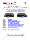
Wireless transceiver computer-to-sign connection (Locus)
Overview
In order to display messages on a sign, the messaging computer must be connected to the sign, such as with a
pair of wireless transceivers (a Master transceiver attached to the messaging computer and a Receive transceiver
attached to a sign).
Wireless transceivers can connect to a sign that is up to 2 miles away. (Actual distance depends on the local
environment, obstructions, electrical interference, and so on.
RS232 cable
(supplied with transceiver)
AlphaEclipse RoadStar sign
Master transceiver
(pn 1088-9307B)
Receive transceiver (inside sign)
(pn 1088-9307B)
Messaging computer
running AlphaNET software
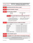
The wiring is connected from the controller board and the regulator board to the transceiver:
The controller board and the
regulator board are located on the
controller plate in the control cube.
See “Internal view” on page 8.
COM0 RS232
Regulator board
Controller board
Wiring
5db omni-directional
antenna (pn 1088-9308A)
COM0 RS232
(on controller board)
Mounting hardware
Do not attach to sign
Power cable
(pn 1088-9206)
20-foot coax cable
(pn 1160-9009A)
DB9-to-DB9 null modem cable
(pn 1088-9204)
Regulator board
(on controller plate)
Receiving transceiver
(pn 1088-9307B)
inside control cube
32
4-foot coax cable
(pn 1180-9034)
Networking
AlphaEclipse RoadStar Sign Installation Instructions (9717-5001)
March 11, 2005
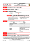
Wireless transceiver computer-to-sign connection (Alpha RF900)
Overview
In order to display messages on a sign, the messaging computer must be connected to the sign, such as with a
pair of wireless transceivers (a server transceiver attached to the messaging computer and a client transceiver
attached to a sign).
Alpha RF900 transceivers have an indoor transmission range of 300 to 500 feet and an outdoor range of 3500
feet line-of-site.
RS232 cable
(supplied with transceiver)
AlphaEclipse™ sign
Client transceiver (inside sign)
Messaging computer
running AlphaNET software
Alpha RF900 Server
The wiring is connected from the controller board and the regulator board to the transceiver:
The controller board and the
regulator board are located on the
controller plate in the control cube.
See “Internal view” on page 8.
COM0 RS232
Regulator board
Controller board
Wiring
900MHz, ISM band
antenna (pn 1211-9201)
COM0 RS232
(on controller board)
Mounting hardware
Do not attach to sign
Power cable
(pn 1088-9206)
20-foot coax cable
(pn 1160-9009A)
DB9-to-DB9 null modem cable
(pn 1088-9204)
Regulator board
(on controller plate)
Receiving transceiver
(pn 1211-2214)
inside control cube
Networking
4-foot coax cable
(pn 1180-9034)
33
March 11, 2005
AlphaEclipse RoadStar Sign Installation Instructions (9717-5001)
Appendix
Serial address of a sign
The serial address of a sign is a number used to identify one sign from another when messages are sent.
Each AlphaEclipse is factory programmed with a serial address. Though a sign’s address can be changed, it is
usually not necessary or desirable to do so.
To determine a sign’s serial address, do one of the following:
34
•
Remove power to the sign and then reapply power — a series of startup messages will appear on the sign.
One of these messages will identify the sign’s serial address and another whether a sign is a Master,
Secondary Master, or a Slave sign.
•
Check the back of the main section of the sign for a label indicating the sign’s serial address and whether a
sign is a Master, Secondary Master, or a Slave sign:
Appendix
AlphaEclipse RoadStar Sign Installation Instructions (9717-5001)
March 11, 2005
How to open a section door
All AlphaEclipse RoadStar sign sections open from the front:
1.
Remove power from the sign. See “Internal view” on page 8 for location of the power switches. Note that
on a two-line sign, both switches must be in the off position to remove power from the sign.
WARNING
Hazardous voltage.
Contact with high voltage
may cause death or serious
injury.
Always disconnect power to
unit prior to servicing. SM1000A
2.
Locate the door locks in each door that is to be removed:
Door locks (circled)
Front of door
3.
Use a 5/32-inch hex tool to open each door lock. Turn counterclockwise to open the latch. Then open the
door by pulling it toward you:
5/32-inch hex tool
(pn 6811-7076)
Open the door slowly to prevent damage to internal components.
Appendix
35
March 11, 2005
AlphaEclipse RoadStar Sign Installation Instructions (9717-5001)
How to remove a section door
A section door must be put back into the same location from where it was removed.
4.
Disconnect the communication cable, DC power, and the light sensor wire harness (control cube only)
from the back of the door:
Communication cable
Light sensor wire harness
(control cube only)
DC power
5.
Remove the door from the cube.
NOTE: Keep fingers clear of hinge notch
when opening, removing, or closing door
to avoid pinching.
Hinge notch
• Rotate the door forward until the hinge notch lines up
with the side of the cube.
• Lift the door straight up.
• Rotate the door away from you.
• Pull the door out.
36
Appendix
AlphaEclipse RoadStar Sign Installation Instructions (9717-5001)
March 11, 2005
(This page intentionally left blank.)
Appendix
37
March 11, 2005
AlphaEclipse RoadStar Sign Installation Instructions (9717-5001)
Assembly drawings
RU ,
RU :$51,1*
/,)7,1 *%5$&.(767 2%(86('3(5
,167$/$7, 21 0$18$/ 21/<
+
/,)7,1 *%5$&.(767 2%(86('7 2/,)76,
21/<' 2127/,)77+(6, *1,),7,667,//
$77$&+('7 27+(6+,33,1 *&5$7(
*1
$
^6((6+((7`
/,)7,1 *%5$&.(76'(6, *1(')25,1,7,$/
,167$/$7, 21 21/<$1'6+ 28/'%(
5(029('$)7(56, *1,6,167$//('
*
6(('(7$,/$
)25,17(51$/
&20321(176
)
%%
^6((6+((7`
62&.(7+($'
&$36&5(:6
23(1:,7+
+(;722/
(
%
&21752//(5 /2&$7('
,1%277205,*+7
)52179,(:
'
&
'(7$,/%
6&$/( %
*5281' /8*
%$&.9,(:
$
&20081,&$7,216&21'8,7+2/(6
32:(5(175<&21'8,7+2/(
38
Appendix
AlphaEclipse RoadStar Sign Installation Instructions (9717-5001)
March 11, 2005
,
*5281' /8*
+
32:(5(175<&21'8,7+2/(
'(7$,/$
)52179,(:
'22565(029('
&20081,&$7,21&21'8,7(175<+2/(6
*
6(('(7$,/$
)25,17(51$/
&20321(176
)
'225:,// 23(1
$7 /($67
62&.(7+($'
&$36&5(:6
23(1:,7+
+(;722/
(
5,*+76,'(9,(:
'225 23(1('
6,1*/( /,1(
5,*+76,'(9,(:
&21752//(5 /2&$7('
,1%277205,*+7
'
&
./ 4%3
2%&%24/ ).34!,,! 4)/ . -!. 5!,&/ 2 0/ 7%2 !.$ !$$) 4)/ .!, ).34!,,! 4)/ . 2%1 5)2%-%.43
4(% / .,9 3%26)# %4// ,3 2%1 5)2%$ !2 % ! 0(),,)03 3# 2%7$2)6 %2 (%84// ,
!.$ ! 4%# (.)# )!. 3 3,/ 44%$",!$ % 3# 2%7$2)6 %2 02/ 6)$ %$
2%-/ 6!, / & !.9 &!34%.%23 / 2 / 4(%2 ./ 4%$ 0! 243 7),, .%' ! 4%4(% 02/ $5#4 7!22!. 49
!,,&!34%.%23 !2 % !.3) ).# (
53% / .,94/0 !.$ "/ 44/- !. ' ,% / 2 6 %24)# !, !. ' ,%34/ -/ 5.4 3)' . $)2%#4,94/
350%23425#452% !,, ).34!,,! 4)/ .3 350%23425#452% $%3)' .3 !.$ #/ .. %#4)/ .3 -534
"% $%3)' .%$!02/ 6 %$"9 ! 1 5!,)&)%$ 3425#45!, %.' ).%%2#!,, !$!0 4)6% -)# 2/ 3934%-3
! 4 &/ 2 3425#452!, %.' ).%%2).' #/ .35,4!. 4#/ .4! #4 ).&/ 2-! 4)/ .
$5%4/ 342%' 4( ,)-)4! 4)/ . / & $)30,!9 35"3425#452% ,!2' %2 3)' .3 7),, 2%1 5)2% -5,4)0,%
$)30,!9 3%#4)/ .3 $)30,!9 3%#4)/ . 3):% 7),,"% /0 4)-):%$&/ 2 02/ $5#4)/ . 9)%,$ !.$ -!9
6!2 9 7)4( %! # ( 3)' .
$%3)' . !.$ $)-%.3)/ .3 !2 % 35"*%#44/ #(!. ' % 7)4(/ 54 ./ 4)# %
%
',0(16,216$5(,1&+$1' 72/(5$1&(6$5(
$6 )2//2:6 81/(6627+(5:,6(63(&,),('
;
;;
;;;
$1*/(6
'(6,*1('%<
/$*
6$$
!
2%,%!3%$ &/ 202/ $ 5# 4)/.
Appendix
$ %3#2)04)/.
3!!
%#/
"9
$! 4%
'$7(
'$7(
'5$:1%<
2%6
$33529('%<
'$7(
1RUWKWK6WUHHW
0LOZDXNHH :,86$
7,7/(
$/3+$ (&/,36( 52$'67$5 0(&+$1,&$/ '(7$,/6
6,=(
'2&80(1712
'
6&$/(
67$786
$
6+7
5HOHDVHG
$
5(9,6,21
RI 7 + ,6 ' 5 $: ,1 *,6 7 + ( 35 23(5 7 < 2) $' $37 ,9( 0 ,& 5 2 6<67 (0 6//& $1 ' 6+ $// 1 27 %( ' 8 3/,& $7 (' : ,7 + 28 7 3(5 0 ,66,21
39
March 11, 2005
AlphaEclipse RoadStar Sign Installation Instructions (9717-5001)
,
$//6,*16 $1'6,*16(&7,216 0867 %( 02817(' 72683(56758&785(
$//,167$/$7,216683(56758&785( '(6,*16 $1' &211(&7,216 0867
%( '(6,*1('$33529(' %< $48$/,),('6758&785$/(1*,1((5
&$// $'$37,9( 0,&526<67(06 $7 )256758&785$/
(1*,11(5,1* &2168/7$17 &217$&7,1)250$7,21
+
*
)
(
5($5,629,(:
'(7$,/ 2)+2:6(&7,216$5($77$&+('$7$06
,167$// *5200(763529,'('%(7:((16,*16(&7,216
$//'$7$$1'32:(5&$%/(6 0867%(5287('7+528*+
7+( *5200(7632:(5$1''$7$&$%/(6 0867%(5287('
7+528*+',))(5(17+2/(632:(5$1'),%(5237,&&$1%(
5287('7+528*+7+(6$0(+2/(,)1(&(66$5<
'
&
*5200(7'(7$,/
6&$/( %
$
40
Appendix
AlphaEclipse RoadStar Sign Installation Instructions (9717-5001)
March 11, 2005
6,*1 6(&7,21 02'(/
180%(5
0RGHO 1XPEHU ([SODQDWLRQ
56;5('
7 %( 02817(' 72683(56758&785(
5( '(6,*16 $1' &211(&7,216 0867
),('6758&785$/(1*,1((5
)256758&785$/
&7,1)250$7,21
56;5('
56;5('
56;5('
56;5('
56;5('
56;5('
56;5('
56;5('
56;5('
56;$0%
56;$0%
56;$0%
56;$0%
56;$0%
56;$0%
56;$0%
56;$0%
56;$0%
56;5('
56;5('
56;5('
56;5('
56;5('
56;5('
56;5('
56;5('
56;5('
56;$0%
56;$0%
56;$0%
56;$0%
56;$0%
56;$0%
56;$0%
56;$0%
56;$0%
56;5('
56;5('
56;5('
56;5('
56;5('
56;5('
56;5('
56;5('
56;5('
56;$0%
56;$0%
56;$0%
56;$0%
56;$0%
56;$0%
56;$0%
56;$0%
56;$0%
56;5('
56;5('
56;5('
56;5('
56;5('
56;5('
56;5('
56;5('
56;5('
56;$0%
56;$0%
56;$0%
56;$0%
56;$0%
56;$0%
56;$0%
56;$0%
56;$0%
5('25$0%(5/$03
+(,*+73L[HO5RZV;
:,'7+3L[HO &ROXPQV
/(''(*5((
/('3,7&+,1PLOOLPHWHUV
PPRUPP
56 52$'67$5
3URGXFW)DPLO\
1RWHV
$OO'LPHQVLRQVï
:HLJKW
6(&7,216
'7+528*+
67%(5287('
5237,&&$1%(
5<
6,*1
ï
ï
:(,*+7
',0$ ',0%
OEV
,
+
*
)
(
'
&
%
',0(16,216$5(,1&+$1' 72/(5$1&(6$5(
$6 )2//2:6 81/(6627+(5:,6(63(&,),('
;
;;
;;;
$1*/(6
'(6,*1('%<
/$*
'$7(
'$7(
'5$:1%<
6$$
$33529('%<
'$7(
1RUWKWK6WUHHW
0LOZDXNHH :,86$
$
7,7/(
$/3+$ (&/,36(52$'67$5 0(&+$1,&$/'(7$,/6
6,=(
'2&80(1712
'
6&$/(
5(9,6,21
67$786
$
6+7
5HOHDVHG
RI 7 + ,6 ' 5 $: ,1 *,6 7 + ( 35 23(5 7 < 2) $' $37 ,9( 0 ,& 5 2 6<67 (0 6//& $1 ' 6+ $// 1 27 %( ' 8 3/,& $7 (' : ,7 + 28 7 3(5 0 ,66,21
Appendix
41
March 11, 2005
AlphaEclipse RoadStar Sign Installation Instructions (9717-5001)
Technical specifications
115 - 230
115 - 230
115 - 230
115 - 230
115 - 230
115 - 230
115 - 230
115 - 230
115 - 230
50/60 2.86 1.49 329.23
50/60 4.08 2.12 469.20
50/60 5.30 2.75 609.17
50/60 6.51 3.39 749.14
50/60 7.73 4.02 889.11
50/60 8.95 4.66 1029.09
50/60 10.17 5.29 1169.06
50/60 11.38 5.92 1309.03
50/60 12.60 6.56 1449.00
Weight
(nearest 10 pound increment)
1
1
1
1
1
1
1
1
1
Watt density (approximate)
(watts per cubic foot)
2
2
2
2
2
2
2
2
2
Rated input power (watts)
4 2 2
6 3 3
8 4 4
10 5 5
12 6 6
14 7 7
16 8 8
18 9 9
20 10 10
Rated input current (230V)
56
84
112
140
168
196
224
252
280
Rated input current (115V)
2.5
2.5
2.5
2.5
2.5
2.5
2.5
2.5
2.5
Rated input frequency (HZ)
32
48
64
80
96
112
128
144
160
Power supply
7
7
7
7
7
7
7
7
7
Width x Height x Depth (inches)
RS6401-07x160-RED
Rated input voltage (volts)
RS6401-07x144-RED
On/Off switch
RS6401-07x128-RED
Fan thermostat
RS6401-07x112-RED
Internal cooling fan
RS6401-07x096-RED
LED driver assembly
RS6401-07x080-RED
LED display assembly
RS6401-07x064-RED
Pitch (inches)
RS6401-07x048-RED
Cols
RS6401-07x032-RED
Rows
Model number
One-line, red, 17.5-inch character
80x20x10.0
120x20x10.0
160x20x10.0
200x20x10.0
240x20x10.0
280x20x10.0
320x20x10.0
360x20x10.0
400x20x10.0
64.6
61.4
59.8
58.8
58.2
57.7
57.4
57.1
56.9
110
160
210
260
310
360
410
470
520
42
8
12
16
20
24
28
32
36
40
4
6
8
10
12
14
16
18
20
4
6
8
10
12
14
16
18
20
2
2
2
2
2
2
2
2
2
2
2
2
2
2
2
2
2
2
115 - 230
115 - 230
115 - 230
115 - 230
115 - 230
115 - 230
115 - 230
115 - 230
115 - 230
50/60
50/60
50/60
50/60
50/60
50/60
50/60
50/60
50/60
5.78 3.00 664.37 80x40x10.0
8.45 4.39 971.91 120x40x10.0
11.13 5.78 1279.46 160x40x10.0
13.80 7.17 1587.00 200x40x10.0
16.47 8.56 1894.54 240x40x10.0
19.15 9.95 2202.09 280x40x10.0
21.82 11.34 2509.63 320x40x10.0
24.50 12.73 2817.17 360x40x10.0
27.17 14.12 3124.71 400x40x10.0
Watt density (approximate)
(watts per cubic foot)
Weight
(nearest 10 pound increment)
128
192
256
320
384
448
512
576
640
Width x Height x Depth (inches)
2.5
2.5
2.5
2.5
2.5
2.5
2.5
2.5
2.5
Rated input power (watts)
32
48
64
80
96
112
128
144
160
Rated input current (230V)
Rated input frequency (HZ)
16
16
16
16
16
16
16
16
16
Rated input current (115V)
Rated input voltage (volts)
RS6401-16x160-RED
On/Off switch
RS6401-16x144-RED
Fan thermostat
RS6401-16x128-RED
Internal cooling fan
RS6401-16x112-RED
Power supply
RS6401-16x096-RED
LED driver assembly
RS6401-16x080-RED
LED display assembly
RS6401-16x064-RED
Pitch (inches)
RS6401-16x048-RED
Cols
RS6401-16x032-RED
Rows
Model number
Two-line, red, 17.5-inch character
65.2 230
63.6 350
62.8 460
62.3 580
62.0 690
61.8 800
61.6 920
61.5 1030
61.4 1150
Appendix
AlphaEclipse RoadStar Sign Installation Instructions (9717-5001)
March 11, 2005
Rated input voltage (volts)
Rated input frequency (HZ)
Rated input current (115V)
Rated input current (230V)
Rated input power (watts)
Width x Height x Depth (inches)
Watt density (approximate)
(watts per cubic foot)
Weight
(nearest 10 pound increment)
RS6401-07x160-AMB
On/Off switch
RS6401-07x144-AMB
Fan thermostat
RS6401-07x128-AMB
Internal cooling fan
RS6401-07x112-AMB
Power supply
RS6401-07x096-AMB
LED driver assembly
RS6401-07x080-AMB
LED display assembly
RS6401-07x064-AMB
Pitch (inches)
RS6401-07x048-AMB
Cols
RS6401-07x032-AMB
Rows
Model number
One-line, amber, 17.5-inch character
7
7
7
7
7
7
7
7
7
32
48
64
80
96
112
128
144
160
2.5
2.5
2.5
2.5
2.5
2.5
2.5
2.5
2.5
56
84
112
140
168
196
224
252
280
4 2
6 3
8 4
10 5
12 6
14 7
16 8
18 9
20 10
2
3
4
5
6
7
8
9
10
2
2
2
2
2
2
2
2
2
1
1
1
1
1
1
1
1
1
115 - 230
115 - 230
115 - 230
115 - 230
115 - 230
115 - 230
115 - 230
115 - 230
115 - 230
50/60
50/60
50/60
50/60
50/60
50/60
50/60
50/60
50/60
4.33
6.29
8.25
10.21
12.17
14.13
16.09
18.05
20.01
2.23
3.24
4.25
5.26
6.27
7.28
8.29
9.30
10.31
497.55
723.01
948.47
1173.93
1399.39
1624.86
1850.32
2075.78
2301.24
80x20x10.0
120x20x10.0
160x20x10.0
200x20x10.0
240x20x10.0
280x20x10.0
320x20x10.0
360x20x10.0
400x20x10.0
97.7
94.6
93.1
92.2
91.6
91.2
90.8
90.6
90.4
110
160
210
260
310
360
410
470
520
Appendix
Rated input voltage (volts)
Rated input frequency (HZ)
Rated input current (115V)
Rated input current (230V)
Rated input power (watts)
Width x Height x Depth (inches)
Watt density (approximate)
(watts per cubic foot)
Weight
(nearest 10 pound increment)
RS6401-16x160-AMB
On/Off switch
RS6401-16x144-AMB
Fan thermostat
RS6401-16x128-AMB
Internal cooling fan
RS6401-16x112-AMB
Power supply
RS6401-16x096-AMB
LED driver assembly
RS6401-16x080-AMB
LED display assembly
RS6401-16x064-AMB
Pitch (inches)
RS6401-16x048-AMB
Cols
RS6401-16x032-AMB
Rows
Model number
Two-line, amber, 17.5-inch character
16
16
16
16
16
16
16
16
16
32
48
64
80
96
112
128
144
160
2.5
2.5
2.5
2.5
2.5
2.5
2.5
2.5
2.5
128
192
256
320
384
448
512
576
640
8
12
16
20
24
28
32
36
40
4
6
8
10
12
14
16
18
20
4
6
8
10
12
14
16
18
20
2
2
2
2
2
2
2
2
2
2
2
2
2
2
2
2
2
2
115 - 230
115 - 230
115 - 230
115 - 230
115 - 230
115 - 230
115 - 230
115 - 230
115 - 230
50/60
50/60
50/60
50/60
50/60
50/60
50/60
50/60
50/60
9.16
13.53
17.91
22.28
26.66
31.03
35.41
39.78
44.16
4.71
6.96
9.22
11.47
13.72
15.97
18.22
20.48
22.73
1052.90
1556.04
2059.18
2562.32
3065.46
3568.61
4071.75
4574.89
5078.03
80x40x10.0
120x40x10.0
160x40x10.0
200x40x10.0
240x40x10.0
280x40x10.0
320x40x10.0
360x40x10.0
400x40x10.0
103.4
101.9
101.1
100.6
100.3
100.1
99.9
99.8
99.7
230
350
460
580
690
800
920
1030
1150
43
March 11, 2005
AlphaEclipse RoadStar Sign Installation Instructions (9717-5001)
1
1
1
1
1
1
1
1
1
115 - 230
115 - 230
115 - 230
115 - 230
115 - 230
115 - 230
115 - 230
115 - 230
115 - 230
50/60
50/60
50/60
50/60
50/60
50/60
50/60
50/60
50/60
4.60 2.38
6.56 3.39
8.52 4.40
10.48 5.41
12.44 6.42
14.40 7.43
16.36 8.44
18.32 9.45
20.28 10.46
Weight
(nearest 10 pound increment)
2
2
2
2
2
2
2
2
2
Watt density (approximate)
(watts per cubic foot)
4 2 3
6 3 4
8 4 5
10 5 6
12 6 7
14 7 8
16 8 9
18 9 10
20 10 11
Width x Height x Depth (inches)
56
84
112
140
168
196
224
252
280
Rated input power (watts)
3.5
3.5
3.5
3.5
3.5
3.5
3.5
3.5
3.5
Rated input current (230V)
32
48
64
80
96
112
128
144
160
Rated input current (115V)
7
7
7
7
7
7
7
7
7
Power supply
Rated input frequency (HZ)
RS8901-07x160-RED
Rated input voltage (volts)
RS8901-07x144-RED
On/Off switch
RS8901-07x128-RED
Fan thermostat
RS8901-07x112-RED
Internal cooling fan
RS8901-07x096-RED
LED driver assembly
RS8901-07x080-RED
LED display assembly
RS8901-07x064-RED
Pitch (inches)
RS8901-07x048-RED
Cols
RS8901-07x032-RED
Rows
Model number
One-line, red, 24.5-inch character
528.60
754.06
979.52
1204.98
1430.44
1655.91
1881.37
2106.83
2332.29
112x28x11.75
168x28x11.75
224x28x11.75
280x28x11.75
336x28x11.75
392x28x11.75
448x28x11.75
504x28x11.75
560x28x11.75
53.0
50.4
49.1
48.3
47.8
47.4
47.1
46.9
46.7
170
250
330
420
500
580
660
750
830
44
Rated input frequency (HZ)
Rated input current (115V)
Rated input current (230V)
Rated input power (watts)
Width x Height x Depth (inches)
16
16
16
16
16
16
16
16
16
32
48
64
80
96
112
128
144
160
3.5
3.5
3.5
3.5
3.5
3.5
3.5
3.5
3.5
128
192
256
320
384
448
512
576
640
8
12
16
20
24
28
32
36
40
4
6
8
10
12
14
16
18
20
5
7
9
11
13
15
17
19
21
2
2
2
2
2
2
2
2
2
2
2
2
2
2
2
2
2
2
115 - 230
115 - 230
115 - 230
115 - 230
115 - 230
115 - 230
115 - 230
115 - 230
115 - 230
50/60
50/60
50/60
50/60
50/60
50/60
50/60
50/60
50/60
9.43
13.80
18.18
22.55
26.93
31.30
35.68
40.05
44.43
4.86
7.11
9.37
11.62
13.87
16.12
18.38
20.63
22.88
1083.95
1587.09
2090.23
2593.37
3096.51
3599.66
4102.80
4605.94
5109.08
112x56x11.75
168x56x11.75
224x56x11.75
280x56x11.75
336x56x11.75
392x56x11.75
448x56x11.75
504x56x11.75
560x56x11.75
Watt density (approximate)
(watts per cubic foot)
Weight
(nearest 10 pound increment)
Rated input voltage (volts)
RS8901-16x160-RED
On/Off switch
RS8901-16x144-RED
Fan thermostat
RS8901-16x128-RED
Internal cooling fan
RS8901-16x112-RED
Power supply
RS8901-16x096-RED
LED driver assembly
RS8901-16x080-RED
LED display assembly
RS8901-16x064-RED
Pitch (inches)
RS8901-16x048-RED
Cols
RS8901-16x032-RED
Rows
Model number
Two-line, red, 24.5-inch character
54.3
53.0
52.4
52.0
51.7
51.5
51.4
51.3
51.2
370
550
730
910
1090
1280
1460
1640
1820
Appendix
AlphaEclipse RoadStar Sign Installation Instructions (9717-5001)
March 11, 2005
Rated input current (115V)
Rated input current (230V)
Rated input power (watts)
Width x Height x Depth (inches)
Watt density (approximate)
(watts per cubic foot)
Weight
(nearest 10 pound increment)
7
7
7
7
7
7
7
7
7
32
48
64
80
96
112
128
144
160
3.5
3.5
3.5
3.5
3.5
3.5
3.5
3.5
3.5
56
84
112
140
168
196
224
252
280
4 2 3
6 3 4
8 4 5
10 5 6
12 6 7
14 7 8
16 8 9
18 9 10
20 10 11
2
2
2
2
2
2
2
2
2
1
1
1
1
1
1
1
1
1
115 - 230
115 - 230
115 - 230
115 - 230
115 - 230
115 - 230
115 - 230
115 - 230
115 - 230
50/60
50/60
50/60
50/60
50/60
50/60
50/60
50/60
50/60
6.34
9.16
11.98
14.81
17.63
20.46
23.28
26.10
28.93
3.27
4.72
6.17
7.62
9.07
10.52
11.97
13.43
14.88
728.53
1053.30
1378.08
1702.86
2027.64
2352.42
2677.20
3001.98
3326.76
112x28x11.75
168x28x11.75
224x28x11.75
280x28x11.75
336x28x11.75
392x28x11.75
448x28x11.75
504x28x11.75
560x28x11.75
73.0
70.4
69.0
68.2
67.7
67.3
67.1
66.8
66.7
180
270
350
440
530
620
700
790
880
Power supply
Rated input frequency (HZ)
RS8901-07x160-AMB
Rated input voltage (volts)
RS8901-07x144-AMB
On/Off switch
RS8901-07x128-AMB
Fan thermostat
RS8901-07x112-AMB
Internal cooling fan
RS8901-07x096-AMB
LED driver assembly
RS8901-07x080-AMB
LED display assembly
RS8901-07x064-AMB
Pitch (inches)
RS8901-07x048-AMB
Cols
RS8901-07x032-AMB
Rows
Model number
One-line, amber, 24.5-inch character
Appendix
Rated input frequency (HZ)
Rated input current (115V)
Rated input current (230V)
Rated input power (watts)
Width x Height x Depth (inches)
16
16
16
16
16
16
16
16
16
32
48
64
80
96
112
128
144
160
3.5
3.5
3.5
3.5
3.5
3.5
3.5
3.5
3.5
128
192
256
320
384
448
512
576
640
4
12
16
20
24
28
32
36
40
4
6
8
10
12
14
16
18
20
5
7
9
11
13
15
16
19
21
2
2
2
2
2
2
2
2
2
2
2
2
2
2
2
2
2
2
115 - 230
115 - 230
115 - 230
115 - 230
115 - 230
115 - 230
115 - 230
115 - 230
115 - 230
50/60
50/60
50/60
50/60
50/60
50/60
50/60
50/60
50/60
13.38
19.73
26.08
32.43
38.78
45.13
51.47
57.82
64.17
6.88
10.14
13.40
16.66
19.92
23.18
26.43
29.69
32.95
1539.08
2269.14
2999.20
3729.26
4459.32
5189.38
5919.43
6649.49
7379.55
112x56x11.75
168x56x11.75
224x56x11.75
280x56x11.75
336x56x11.75
392x56x11.75
448x56x11.75
504x56x11.75
560x56x11.75
Watt density (approximate)
(watts per cubic foot)
Weight
(nearest 10 pound increment)
Rated input voltage (volts)
RS8901-16x160-AMB
On/Off switch
RS8901-16x144-AMB
Fan thermostat
RS8901-16x128-AMB
Internal cooling fan
RS8901-16x112-AMB
Power supply
RS8901-16x096-AMB
LED driver assembly
RS8901-16x080-AMB
LED display assembly
RS8901-16x064-AMB
Pitch (inches)
RS8901-16x048-AMB
Cols
RS8901-16x032-AMB
Rows
Model number
Two-line, amber, 24.5-inch character
77.1
75.8
75.1
74.7
74.5
74.3
74.1
74.0
73.9
390
580
770
960
1150
1350
1540
1730
1920
45
March 11, 2005
AlphaEclipse RoadStar Sign Installation Instructions (9717-5001)
(This page intentionally left blank.)
46
Appendix