1
Twisted Pair Transmitter/Receiver
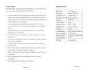
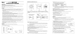
Installation diagram
Twisted pair cable connection
No.
Signal type
Cable color
1
R+
green
white
2
R-
green
3
AUDIO+
orange
white
4
G/H+
blue
5
G/H-
blue white
6
AUDIO-
orange
7
B/V+
brown
white
8
B/V-
brown
External control and adjustment
Video description:
① CR-200T/R net cable connection. Don’t connect this net port cable directly to the Ethernet
port of PC.
② Connect to the output port of +12VD power adapter. Inside is +, outside is -.
③ Stereo input.
④ Local VGA input. Signal type: RGBHV.
⑤ Local VGA output.
⑥ Terminal stereo output.
⑦ Terminal VGA signal input.
- 2 -