1
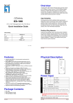
Global R & D
GSC
User Manual
First Issue
20.03.2006
Compiled by: Shaun Sequeira
Changed by: Kari Suihkonen
Checked by: Kari Suihkonen
Approved by:
Date: 20.03.2006
© 2006 Kone Corporation
Product code: LCE
Drawing no: XXXXXX
LCEUIO DONGLE
USER MANUAL
Copyright © 2006 KONE Corporation. All rights reserved.
1 (4)
EDMS Code
884634en.A.2
Issue: 0.1
No of Pages: 4
Language: en
SW: Word 2000
Global R & D
GSC
User Manual
First Issue
28.02.2006
2 (4)
EDMS Code
884634en.A.2
TABLE OF CONTENTS
1
INTRODUCTION.................................................................................................... 3
2
BLOCK DIAGRAM ................................................................................................ 3
3
HOW TO OPEN LCE USER INTERFACE WITH THE TOOL....................... 4
Copyright © 2006 KONE Corporation. All rights reserved.
User Manual
First Issue
28.02.2006
Global R & D
GSC
1
3 (4)
EDMS Code
884634en.A.2
Introduction
The user interface of all LCE based elevators, which have 6.X.X based software or newer will be
locked after 10000 starts. The LCEUIO tool can be used to unlock the LCE user interface and the
serial port of the CPU board for elevators, which have 6.7.18 or newer software.
This document explains the functionality and use of the LCE User Interface Opening
(LCEUIO) tool.
2
Block Diagram
A
LED
Power button
B
DC
Figure 1
The user interface of the tool contains following main parts (figure 1).
•
•
•
•
•
•
•
Port A (D9 connector) will be connected to corresponding connecter on LCECPU40,
LCECPU561 or LOPCB board in MAP.
Power button Power switch is used to start and shut down the battery power.
Led is used for diagnostic purposes. Different warnings and errors have been defined in
the table.
Port B (D9 connector) is supposed to be used when troubleshooting tools (LCETERM)
are connected to the tool.
DC provides a connector to extern power supply, 10 – 24V (for example Mascot
9525/12VD).
On the backside of the tool there is a 9V battery behind the cover.
2 extent cables including in the package. One for LCECPU20 for different adapter.
Another one for LCECPU40 or LCELOB for easy connection.
Copyright © 2006 KONE Corporation. All rights reserved.
User Manual
First Issue
28.02.2006
Global R & D
GSC
LED
RED
State
Lit for 10 sec
RED
RED
Two blinks every 10 sec
Three blinks every 10 sec
RED
GREEN
Continuous blinking
Lit for 10 sec
GREEN
Blinking
GREEN
ORANGE
One Blink every 10 sec
Blinking
3
4 (4)
EDMS Code
884634en.A.2
Description
Tool has been used for 200 times and it is
locked. Tool must be re-initialized with the
re-initialization tool, before it can be used
again.
The tool can’t open LCE user interface.
The tool can't communicate with elevator.
This can occur, if there is communication
problem or LCECPU software does not
support the LCEUIO tool.
Internal error in the tool. Tool is broken.
The tool communication with elevator is OK
and the LCE user interface is open.
The tool receives a message from the
LCECPU.
The tool has been re-initialized.
The tool receives a message from the
LCECPU and tool has been used over 150
times. This is warning, that the tool should
be re-initialized soon.
How to open LCE user interface with the tool
The operating sequence is:
1. Connect the tool (port A) to the RS232 port on LCECPU40, LCECPU561 or LOPCB
board either using cable coming with the tool or connecting port A directly into the
connector.
2. Switch on the RS232 enable switch on LOPCB board in MAP.
3. Push the power button until the led turns on.
4. When the led has green or orange light on, the LCE user interface is open.
5. Switch off the RS232 enable switch on LOPCB board in MAP.
6. Test the Menu access. (If OK, disconnect the device otherwise repeat the step 2-5)
Copyright © 2006 KONE Corporation. All rights reserved.