1
User’s Manual
37
Chapter 5. LAN Adapter
The on-board LAN adapter is using Single Chip Fast Ethernet Controller that is highly
integrated and requires no “glue” logic external memory on board. It runs in the bus master
mode and directly sending/receiving Ethernet packet to/from memory. The On-board LAN
adapter can directly fetch the system CPU. Also, it can transfer data Directly between I/O
devices and system memory in the 32-bit bus master mode that provides low CPU utilization.
It complies with the IEEE 802.3u standard, IEEE802.3 standard and PCI Local Bus version
2.1 and transmits data on the network at 100 Mbps or 10 Mbps. It also operates in full-duplex
mode that doubles the network speed up to 20/200 Mbps when working with Fast
Switching Hub. Built-in one RJ-45 port for connection of 100Base-TX Fast Ethernet or
10Base-T Ethernet network, and automatically senses the connection type.
5-1. Features
• Full compliancy with PCI Rev. 2.1
• Complies with the Ethernet/IEEE 802.3u 100Base-TX and 10 Base-T industry
standard
• Supports full-duplex operations, thus doubling the network speed up to 20Mbps on 10
•
•
•
•
•
Base-T Ethernet or 200Mbps on 100 Base-TX Fast Ethernet when setting in full duplex
mode
Two LED indicators to report network status
One RJ-45 connector with Auto-sense cable type of 10 or 100Mbps network operation
Supports PCI clock speed up to 33MHz, capable of zero wait states
Provides a comprehensive setup program for displaying the adapter configuration and
includes diagnostic on board or network tests.
Complete drivers for Novell, ODI, SCO UNIX, LAN Manager, Windows NT and
Windows 95/98 Packet driver etc
38
The ENDAT-3203M/3220M System Board
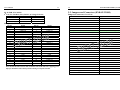
5-2. UTP Cable / RJ-45 Jack Definition
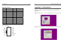
Straight through twisted pair cable is typically used to connect a hub to a server or
workstation. In a straight through connection, Pin 1 at the server, Pin 2 at the hub connects to
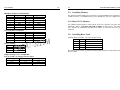
Pin 2 at the server, and so on. Figure A-1 shows the locations of pins on a standard RJ-45 plug
on a twisted-pair cable.
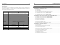
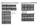
Table A-1 shows the wiring in a straight-through twisted-pair cable (Pins 4, 5, 7 and 8 are not
used).
Twisted Pair
Number
1
2
Pin Number
1
2
3
6
Signal
Description
TD+
TD–
RD+
RD–
To
Æ
Æ
RJ-45 Connector Pin Assignments
Figure A-1 shows the RJ-45 Connector pin assignments
Pin
Number
1
2
3
6
Signal
Description
TD+
TD–
RD+
RD–