1
Scottish Health Technical Memorandum 64 SHTM Building Component Series Sanitary Assemblies December 2009 SHTM 64 Sanitary Assemblies - Building Component Series Contents page 1. 1.1 1.4 1.6 1.11 Introduction ......................................................................................4 Background........................................................................................4 Scope and status ...............................................................................4 Relationship to other data ..................................................................5 Terminology .......................................................................................6 2. 2.1 2.2 2.32 2.54 2.78 2.81 2.82 2.84 2.90 2.93 2.96 2.97 Design and specification notes ......................................................8 User requirements..............................................................................8 Soil assemblies ..................................................................................8 Waste appliances.............................................................................11 Supply fittings...................................................................................13 Waste fittings ...................................................................................16 Special requirements .......................................................................16 Accessories......................................................................................16 Cleaning and disinfection .................................................................17 Maintenance and replacement.........................................................18 Concealed services..........................................................................18 Bacterial growth ...............................................................................19 Fixings and loadings ........................................................................19 3. Product selection criteria ..............................................................20 4. Assembly and component data sheets........................................22 Sheet 1: Disposal unit assemblies for the disposal of liquid and solid waste in connection with clinical procedures..................................................23 Sheet 2: Plaster sink assembly for use in connection with plaster preparation.......................................................................................29 Sheet 3: Janitorial unit....................................................................................32 Sheet 4: Scrub-up trough assemblies for use in connection with surgical washing of forearms and hands .......................................................34 Sheet 5: Sink and sink top assemblies for use in connection with clinical procedures .......................................................................................38 Sheet 6: Sink and sink top assemblies for use in connection with domestic services procedures .........................................................................41 Sheet 7: Basin assemblies for use in connection with clinical procedures ...474 Sheet 8: Basin assemblies for use in connection with personal washing (face, forearms and hands etc) ..................................................................47 Sheet 9: Basin assemblies for hand-rinsing only............................................50 Sheet 10: Bidet assembly for use in connection with clinical procedures.........53 Sheet 11: Hospital pattern urinal ......................................................................55 Version 1.0: December 2009 Page 2 of 88 Health Facilities Scotland, a Division of NHS National Services Scotland SHTM 64 Sanitary Assemblies - Building Component Series Sheet 12: WC for fully ambulant and ambulant disabled users.........................58 Sheet 13: WC for assisted ambulant disabled and wheelchair users................61 Sheet 14: Bath assembly for use in connection with personal bathing .............64 Sheet 15: Data sheets for taps, traps, wastes and floor outlets used in assemblies .......................................................................................67 References.......................................................................................................84 Useful websites...............................................................................................88 Disclaimer The contents of this document are provided by way of general guidance only at the time of its publication. Any party making any use thereof or placing any reliance thereon shall do so only upon exercise of that party’s own judgement as to the adequacy of the contents in the particular circumstances of its use and application. No warranty is given as to the accuracy, relevance or completeness of the contents of this document and Health Facilities Scotland shall have no responsibility for any errors in or omissions therefrom, or any use made of, or reliance placed upon, any of the contents of this document. Version 1.0: December 2009 Page 3 of 88 Health Facilities Scotland, a Division of NHS National Services Scotland SHTM 64 Sanitary Assemblies - Building Component Series 1. Introduction Background 1.1 This is one of a series of Scottish Health Technical Memoranda (SHTMs) which provides specification and design guidance, not adequately covered by current British Standards (BS), on building components for health buildings. The guidance given in this document applies to all new capital projects and whenever refurbishment or repair is required to existing facilities. A full Reference schedule is provided at the end of this document, including Acts and Regulations, Health Facilities Scotland (HFS) guidance, DoH Resources and British Standards. 1.2 1.3 The numbers and titles of the SHTMs: 54 User manual; 55 Windows; 56 Partitions; 57 Internal glazing; 58 Internal doorsets; 59 Ironmongery; 60 Ceilings; 61 Flooring; 62 Demountable storage system; 63 Fitted storage system; 64 Sanitary assemblies; 66 Cubicle curtain track; 67 Laboratory fitting out systems; 69 Protection. The technical information in this series is the result of research and development funded by the Department of Health as part of collaborative working arrangements over a number of years between the Department, the NHS and industry. Scope and status 1.4 This SHTM contains guidance to assist the design team in the selection, specification and application of sanitary assemblies in healthcare buildings. Version 1.0: December 2009 Page 4 of 88 Health Facilities Scotland, a Division of NHS National Services Scotland SHTM 64 Sanitary Assemblies - Building Component Series 1.5 The content of this SHTM does not diminish either the manufacturer’s responsibility for fitness for purpose of products or the team’s responsibility for selection and application of products to meet project requirements. Design teams are also are reminded of their obligations under The Construction (Design and Management) Regulations 2009 to ensure safe construction. It does not diminish the manufacturer’s responsibility for supplying goods fit for purpose nor the design team’s responsibility for selecting assemblies to meet project requirements. Relationship to other data 1.6 This SHTM was prepared for publication in September 2009 and is adapted from core text provided by the Estates and Facilities Division of the Department of Health, England. The main sources of data used in its preparation are listed in the References section. Readers should ensure they use the latest edition of all building legislation, British Standards, Health and Safety Regulations etc, and give first preference to products and services from sources which have been registered under a quality assurance procedure. 1.7 Suppliers offering products other than to British Standards should provide test evidence to show their products are at least equal to such standards. Reference should also be made to the acceptability of water fittings as approved by the Water Regulations Advisory Scheme (WRAS) and published in the ‘Water Fittings and Materials Directory’ (www.wras.co.uk). 1.8 This SHTM is intended to be read in conjunction with SHTM 2040: ‘The control of Legionella, hygiene, ‘safe’ hot water, cold water and drinking water systems’, Health Building Note (HBN) 00-02: ‘Sanitary spaces’ and Scottish Health Facilities Note (SHFN) 30: ‘Infection control in the built environment’ in addition to SHTMs 56: ’Partitions’, 62: ’Demountable storage system’, 63: ‘Fitted storage system’ and 67: ‘Laboratory fitting out systems’ in this series and also HTM 69: ‘Ducts and panel assemblies’. The design team should make reference to this SHTM and give early consideration to sourcing sanitary assemblies and duct panels for their project. Some manufacturers offer complete pre-assembled units. 1.9 This guidance should be used in conjunction with sections of the National Building Specification (NBS) relevant to sanitary assemblies. NBS is a library of standard specification clauses covering most kinds of building work and comprising a wide range of clauses with accompanying guidance notes. All clauses are optional, and their combination into a job specification is left to the specifier. NBS has great flexibility and it can be adapted to suit the technical needs and preferences of different projects, organisations and specifiers. Specifications go out of date as a result of technical innovation or major review of a key BSI document. As NBS sections become affected by such major changes, they are re-issued to members of the subscription service. Users are advised to ensure that they refer to the current edition. Refer to the NBS website at www.thenbs.com Version 1.0: December 2009 Page 5 of 88 Health Facilities Scotland, a Division of NHS National Services Scotland SHTM 64 Sanitary Assemblies - Building Component Series 1.10 Any enquiries regarding the technical content of this SHTM should be e-mailed to [email protected] Terminology 1.11 Throughout this SHTM the following definitions apply: General pattern - for use by hospital staff, patients and the public in general i.e. in other words, non-clinical use; Hospital pattern - for use by clinical staff in connection with clinical procedures. Sanitary assembly - an assembly comprising a soil or waste appliance and appropriate supply and waste fittings; Soil appliance - an appliance for the reception and discharge of excretory matter; Supply fitting - a fitting to control or regulate the supply of water, commonly used with an appliance; Waste appliance - an appliance for the reception of water for ablutionary, cleansing, or culinary purposes and its discharge after use; Waste fitting - a fitting to conduct the discharge from an appliance and to connect to pipework. Version 1.0: December 2009 Page 6 of 88 Health Facilities Scotland, a Division of NHS National Services Scotland SHTM 64 Sanitary Assemblies - Building Component Series Figure 1: Handing of an appliance is determined from the front of the appliance Version 1.0: December 2009 Page 7 of 88 Health Facilities Scotland, a Division of NHS National Services Scotland SHTM 64 Sanitary Assemblies - Building Component Series 2. Design and specification notes User requirements 2.1 The design team should identify user requirements for sanitary assemblies from Activity DataBase (ADB) and then use the data sheets in Section 4 of this SHTM to identify appropriate assemblies. Soil assemblies Relationship between appliances and fittings 2.2 The relationship between soil appliances and the fittings that make up the complete assembly is critical. 2.3 Therefore, disposal units, urinals and WCs should be treated as assemblies for the purposes of design, specification, procurement and installation. Disposal units 2.4 A hospital pattern disposal unit should be provided in clinical areas for the disposal of solid and liquid waste, the contents of vomit bowls, drainage bags and urine bottles. 2.5 The unit can also act as a standby in the event of the failure of a bed-pan disposal unit (macerator). Urinals 2.6 Bowl urinals are more hygienic and easier to install than slabs. 2.7 Assemblies of one, two and three bowls are available in the hospital pattern assembly with concealed services and cistern. 2.8 Water economy should be considered when choosing urinals. 2.9 Additionally, waterless urinals could be considered. Using an appropriate cleaning regime, waterless urinals can eliminate all supply services (resulting in better hygiene), reduce duct depth and eliminate the splashing, spray and medium for bacteria associated with water-fed urinals. WCs 2.10 Hospital pattern WCs should be rimless, wash-down pans and be of the ‘backto-wall’ or ‘wall-hung’ type with concealed cistern and services. Version 1.0: December 2009 Page 8 of 88 Health Facilities Scotland, a Division of NHS National Services Scotland SHTM 64 Sanitary Assemblies - Building Component Series 2.11 Access for sanitary chairs and wheelchairs should be carefully considered. This will involve coordinating the dimensions of chairs with those of WC assemblies and any necessary adjustment to the location of the WC in relation to the wall behind it, or to the height from floor level, to facilitate transfer of patients to and from the chair. 2.12 The Building (Scotland) Regulations require adequate provision of, and the maximum travel distance to, accessible WC facilities. Consideration will be required for suitable provision of such facilities in all areas/departments for use by patients and staff and also general areas where they may be required for use by visitors. 2.13 For further information refer to HBN 00-02: ‘Sanitary spaces’, the Building (Scotland) Regulations, and BS 4751 ‘Mobile sanitary chairs’. 2.14 All pans should have a horizontal or ‘P’ outlet so that the soil pipe can be connected above floor level. This gives flexibility in setting out pans and pipework and allows access to the joint for both installation and maintenance. 2.15 A variety of WC connectors are available which can accommodate different configurations between the outlet and the soil pipe (see BS 5627:1984 ‘Specification for plastics connectors for use with horizontal outlet vitreous china WC pans’). 2.16 Suitable access must be provided to allow the fitting of the WC connector to be carried out properly. This can be provided either from the rear within a duct or by access panels on the room side. 2.17 Flushing arrangements are traditionally lever-operated. However, dual-flush, anti-vandal pneumatic push-buttons, flush plates or sensor operation may also be considered. Designers and specifiers must always consider people with disabilities and what will suit them. 2.18 In all areas, a visual contrast between WC seat and pan should be provided (see HBN 00-02). Note: WC pans for use in prison hospitals and mental health facilities are not covered by this SHTM. For WCs in acute facilities where children and young people receive treatment and care, see SHPN 23: ‘Hospital accommodation for children and young people’ (forthcoming). Basins 2.19 Basins should have a smooth form and easily cleaned surfaces. Overflows should not be provided for infection control reasons. 2.20 Three sizes of basin should fulfil most of the user requirements in health buildings: Version 1.0: December 2009 Page 9 of 88 Health Facilities Scotland, a Division of NHS National Services Scotland SHTM 64 Sanitary Assemblies - Building Component Series large basins - for use in clinical areas for ‘scrub-up’ purposes, and for use by seated or wheelchair patients, for which wide shallow basins should be selected; medium basins - for use in clinical procedures and in general areas/domestic services; small basins - for use inside WC cubicles/stalls, food preparation areas and similar locations. Generally described as being for hand rinsing, or hand washing, under running water only. Hospital pattern 2.21 Hospital pattern basins should be used in clinical procedures with safe, integral thermostatically (TMV3 D08) controlled water and wall-mounted single leveraction or sensor taps with concealed/ducted services. 2.22 Washing of hands and forearms is carried out under running water, and therefore a medium, or often a large, integral back-outlet basin with no plug is recommended. This assembly should maintain the level of hygiene required in clinical areas. See also SHFN 30: ‘Infection control in the built environment’, which gives additional guidance. General pattern 2.23 General pattern basins with tap-holes should only be used for general areas/domestic services with thermostatically (TMV3 D08) controlled maximum hot water temperature and concealed/ducted services. 2.24 Washing is in a reservoir of water; therefore a bowl with plug is recommended. Plugs should be attached to an open-link chain which should be panel-mounted. 2.25 Where medium or small basins are selected with a monobloc pillar mixer tap (TP6) the basin should be specified with a single 35mm tap-hole. Care must be taken when considering a small basin to ensure that the basin and tap size allow adequate room for washing hands. Basin selection 2.26 When selecting taps for clinical procedures, and certain activities in foodpreparation and laboratory areas, taps and supply fittings will be required to be operated without the use of hands. 2.27 Fittings actuated by a proximity sensor are now a preferred alternative to leveraction taps. 2.28 The design team should select the appropriate combinations of basins and taps illustrated on the assembly data sheets for: clinical procedures (see Sheet 7); personal washing (see Sheet 8); Version 1.0: December 2009 Page 10 of 88 Health Facilities Scotland, a Division of NHS National Services Scotland SHTM 64 Sanitary Assemblies - Building Component Series 2.29 hand-rinsing (see Sheet 9). No physical barriers should exclude people with disabilities from using the appropriate service or equipment. Baths 2.30 General baths (that is, baths used for non-assisted personal bathing) have no tap-holes and should be used with wall-mounted mixer taps offering a safe and thermostatically (TMV3 D08) controlled maximum temperature (see Sheet 14). 2.31 Mechanically operated variable-height baths are recommended for assisted bathing. These types of bath are not covered in this guidance. See HBN 00-02 for spatial requirements, size and position of components used in assisted bathing. Waste appliances Bidets 2.32 Bidets (see Sheet 10) are generally used by patients in clinical areas. The appliance should be rimless with an over-rim supply, preferably with sensor operation. The water supply should be controlled by a TMV3 D08 thermostatic mixer valve to prevent scalding. Floor outlets 2.33 The general pattern floor outlet consists of a drainage outlet plus grating for use with a flexible hose fitted with appropriate back-siphonage protection. 2.34 This is used to rinse areas or to dispose of the contents of floor-washing machines. 2.35 The hospital pattern floor outlet consists of a drainage outlet covered by a small grating. It is intended mainly for use in showers in clinical areas. The floor finish should be dressed into the flange of the grating. Plaster sinks 2.36 Plaster sinks in clinical areas have a lift-out strainer basket and wall-mounted taps. A plaster sink assembly is described in Sheet 2. Scrub-up troughs 2.37 Scrub-up troughs should be provided to enable one or more surgeons and nurses to scrub their hands and forearms. 2.38 Troughs should be wall-hung and fitted with a single waste outlet. Version 1.0: December 2009 Page 11 of 88 Health Facilities Scotland, a Division of NHS National Services Scotland SHTM 64 Sanitary Assemblies - Building Component Series 2.39 Taps should be wall-mounted and deliver safe, thermostatically (TMV3 D08) controlled hot water. A scrub-up trough assembly is described in Sheet 4. 2.40 For infection control reasons sensor-controlled fittings are generally required for controlling the flow of water at scrub-up troughs and these can also offer the additional benefit of controlled run times. The relationship between the taps and the trough is critical in order to avoid splashing. Showers 2.41 Showers in clinical areas should be provided in shower rooms with wheelchair access. The floor should be laid to falls to a waste outlet set into the floor. Supply fittings should be wall-mounted. 2.42 Flexible hose to hand-held showerheads should be provided, and the design of the unit should be such that the head cannot become immersed in water, to accord with back-siphonage prevention requirements. It must be constrained to give a type AUK3 air gap above the spillover level of the bath or shower tray, and any other fluid Category 5 risk (for example a WC), by a robust means that cannot be removed without destroying the fitting. 2.43 Shower controls should be positioned so as to allow manipulation without the operator, and/or assistant, getting wet (see HBN 00-02). Showers in clinical areas must be thermostatically controlled (TMV3 D08) to reduce the risk of scalding or thermal shock should either water supply fail. 2.44 Showers in general areas for use by staff should be provided with shower trays. These must take into account their suitability for use by disabled staff (including appropriate supply fittings and grab rails). See also HBN 00-02. 2.45 Deluge showers will generally be supplied via their own dedicated storage tank, which should be flushed weekly. Such installations to comply with the recommendations of SHTM 2040: ‘The control of legionellae in healthcare premises’ (to be replaced by SHTM 04-01). Details of supply fittings and assemblies are not covered by this SHTM, and advice should be sought from specialists/manufacturers. 2.46 Where filters are provided, the recommended maintenance procedures should be followed. Sinks and sinktops 2.47 A range of single-bowl and double-bowl sinks with or without integral drainers and/or worktops are available. They should have a smooth form and easilycleaned surfaces. Overflows are not provided, as they are unhygienic. Sinks and sinktops are available in various sizes and materials to suit the recommendations in this SHTM and the specific dimensional recommendations of SHTM 62: ‘Demountable storage systems’, SHTM 63: ‘Fitted storage systems’ and SHTM 67: ‘Laboratory fitting-out systems’. Sinks with integral tops are available in a variety of materials as well as stainless steel, and the Version 1.0: December 2009 Page 12 of 88 Health Facilities Scotland, a Division of NHS National Services Scotland SHTM 64 Sanitary Assemblies - Building Component Series appropriate material should be selected to reflect the intended use. SHTM 67 offers further guidance on selection of materials. 2.48 In clinical procedures, sinks or sinktops (without tap-holes) with wall-mounted lever-action bib taps and concealed/ducted services should be used. 2.49 Sinks or sinktops with tap-holes should be used for general use/domestic services together with separate lever-action pillar taps (TP3). These sinks should take a plug (with screw-stay to the panel). 2.50 The design team should select the appropriate combination of sink integral drainer or worktop and taps illustrated on the assembly data sheets for: janitorial units, (see Sheet 3); clinical procedures, (see Sheet 5); general use/domestic services, (see Sheet 6). 2.51 All sinks (with or without tap-holes) should be supplied via separate bib or pillar taps (see also SHTM 2040). 2.52 Kitchen sinks should be subject to a ‘duty of care’ risk assessment. When temperatures are in excess of 46°C, ‘scald risk’ warning notices will require to be displayed. Overflows 2.53 Overflows to sinks, basins, baths and bidets are not recommended, as they constitute a constant infection control risk. This is much more significant than the possible risk of damage due to water overflowing (WCs have an internal overflow). This recommendation does not apply to staff residential accommodation, but does apply to patient areas including en-suite and general public toilet areas. Most of the components in this SHTM are specified with no overflow. In situations where an overflow is required, such as in a plaster sink, a standing waste which incorporates an overflow may be used. Supply fittings Source of supply 2.54 All installations must comply with the Water Supply (Water Fittings) Regulations, framed to avoid the risk of contamination of the mains water supply. In residential buildings, the regulations require a direct connection to the cold connection on a tap for drinking water – normally that to the kitchen sink. 2.55 For further information see SHTM 2040 and the ‘Water Regulations Guide’ published by WRAS. Version 1.0: December 2009 Page 13 of 88 Health Facilities Scotland, a Division of NHS National Services Scotland SHTM 64 Sanitary Assemblies - Building Component Series Water conservation 2.56 The need to conserve water must always be considered when selecting sanitary assemblies and supply fittings. 2.57 Considerable savings of both hot and cold water can be made by specifying showers rather than baths and taps that include flow regulation or self-closing for hand rinsing. Use of compliant dual flushing WC cisterns and waterless urinals in public general toilet areas constitutes a major contribution to water saving. Pipework 2.58 Pipework should be planned to avoid dead-legs that can become stagnant. This is hazardous, as it can create conditions suitable for organisms like Legionella to multiply. In addition, they are wasteful of heat and can cause corrosion of pipes and fittings by allowing sediment to be deposited. For further guidance, see SHTM 2040. 2.59 Isolating valves should be provided to isolate each individual appliance. 2.60 Pipe clips on exposed pipework should be specified and installed to avoid injury to staff and patients from sharp edges or the like. Water pressure 2.61 As far as possible, the engineering services installation should be designed to ensure minimum pressure differential between hot and cold water supply pipes at the point of connecting the control fitting. This will improve the performance of sanitary assemblies, helping to avoid the use of expensive supply fittings such as pressure-regulating valves. Water temperature 2.62 The water temperature at point of delivery should be controlled by one of the methods described below as appropriate to user requirements. Provided certain requirements are met (notably that hot and cold pressures are balanced and from a common source, and that the outlet air gap is appropriate), the Water Supply (Water Fittings) Regulations permit blending within the supply fitting. 2.63 Where the requirements cannot be met, but the hot supply is ‘wholesome’, mixing within the fitting is still acceptable providing appropriate inlet backflow prevention protection is employed. 2.64 An alternative solution is the use of supply fittings that maintain separate hot and cold water up to the point of discharge. Manual control 2.65 Separate hot and cold water taps or valves that the user controls manually. Version 1.0: December 2009 Page 14 of 88 Health Facilities Scotland, a Division of NHS National Services Scotland SHTM 64 Sanitary Assemblies - Building Component Series Individual thermostatic control 2.66 Thermostatic mixing of hot and cold water is by a valve at a fitting. The maximum water temperature required may be set and locked on the valve. 2.67 The design team should refer to SHTM 2040 when considering the problems of safety, particularly the risk of scalding young children and older people. 2.68 To reduce the risk of an outbreak of Legionnaires’ disease occurring, cold water should be stored and distributed at a temperature below 20°C and hot water should be stored at a temperature of a minimum of 60°C and distribution controlled to a temperature of a minimum of 55°C. 2.69 The safety of users, particularly some children and older people, would be compromised if they were allowed to use washing or bathing facilities supplied with water at this temperature (that is, immersion in, or exposure to, running hot water). This risk can be reduced by the installation at each hot outlet of a locally adjustable thermostatic mixing valve (see SHTM 2040 for guidance on safe water temperatures). Valves of this type are unaffected by changes in water pressure and should automatically and quickly close the hot or cold supply if either supply fails. 2.70 Vigilance will still be required to ensure that vulnerable patients using sinks in kitchens are not in prolonged contact with water that could be in excess of these temperatures. Water delivery 2.71 The control of water delivery at point of use – on/off and hot/cold – may be achieved in several ways and in several different combinations. 2.72 Supply fittings are more normally controlled by hand manipulation of a tap head, which may be press-down-shroud or a lever. 2.73 Fittings are now available in which the flow of water is initiated by means of a sensor switch. Such devices may well have considerable application in high-risk areas such as operating theatres and burns units. These are also effective in reducing water waste and therefore running costs. 2.74 Other fittings are now available in which the flow of water is initiated and terminated by an integral, thermostatic single lever. Positioning supply fittings 2.75 Supply fitting services should be concealed. Consideration should be given to fittings that can be serviced and/or maintained without the need to remove any panels. Version 1.0: December 2009 Page 15 of 88 Health Facilities Scotland, a Division of NHS National Services Scotland SHTM 64 Sanitary Assemblies - Building Component Series Back-siphonage 2.76 Water regulations now differentiate the level of back-siphonage protection required by the class of risk associated with the receiving vessel. As a general rule, hospital applications of even domestic ablutionary arrangements are elevated to class 4 or class 5 risk and as such, require that supply fittings on baths, basins and sinks etc. with fixed outlets shall be arranged so that the discharge point creates an AUK3 air gap of twice the inlet diameter and never less than 25 mm above the spill-over level of the appliance. 2.77 Concealed showers with fixed-position adjustable heads are recommended, but when flexible hoses with sliding and hand-held spray attachments are unavoidable, special measures must be taken to prevent back-siphonage. The proximity of any adjacent sanitaryware should be considered. The ‘Water Regulations Guide’ is the best source of information on this issue. Waste fittings 2.78 The waste fittings included in this SHTM are outlets and traps. 2.79 All outlets are unslotted for use with appliances without overflows. There are two types: one with a flush grating and the other with a recessed grating, plug, chain and stay. Plugs are recommended only where it is necessary to retain water in an appliance. This includes basins for general use, baths and sinks. Where this is not recommended, plugs should be omitted and the flush-grating type used. 2.80 Bottle traps for use with waste appliances should be plastic with a white finish. Special requirements 2.81 This SHTM does not cover special requirements for such as squatting WC pans, variable height baths, autopsy tables, birthing pools and drinking fountains. Accessories 2.82 Accessories such as toilet-roll holders, grab rails, mirrors, soap dispensers and towel rails are not included in this SHTM. However, they should be subject to a set of minimum standards, with medical/clinical issues at the core of the criteria. 2.83 For the spatial relationships for the above accessories and the positioning of grab rails in accessible WCs, see HBN 00-02: ‘Sanitary spaces’. Version 1.0: December 2009 Page 16 of 88 Health Facilities Scotland, a Division of NHS National Services Scotland SHTM 64 Sanitary Assemblies - Building Component Series Cleaning and disinfection Hygiene and cleaning 2.84 Control and Prevention of Healthcare Associated Infection (HAI) is a priority issue for NHSScotland, both in respect of the safety and well being of patients and staff and also the resources consumed by potentially unavoidable infections. Healthcare Associated Infection (HAI) is a complex issue involving the many different elements of patient care and provision. Due to its multi-factorial nature there is a need to develop a holistic approach to combating the spread of infection within the built environment. It is imperative that those involved in the design and planning, construction and refurbishment and on-going maintenance of the healthcare facility have a sound knowledge of prevention and control of infection in the built environment. SHFN 30 and HAI-SCRIBE aim to provide information on the prevention and control of infection, and on the prevention of cross-infection and cross contamination in healthcare facilities, to those responsible for the planning, design and maintenance of such facilities. Cleaning is an essential part of the multi-disciplinary approach in improving patient, staff and public safety. Safe clinical care is supported through ensuring high standards of hygiene and related measures to tackle HAI in the healthcare environment. Cleaning regimes including frequency of cleaning should be addressed in line with current national guidance together with any additional Local Management requirements. Relevant Provisions of current guidance, standards and Codes of Practice for cleaning of healthcare premises and including the latest technical requirements are embodied in the following documents: SHFN 30: Infection Control in the built environment: Design and Planning NHSScotland Property and Environment Forum August 2005; HAI-Scribe (Healthcare Associated Infection System for Controlling Risk in the Built Environment) NHSScotland Property and Environment Forum August 2005; The NHSScotland National Cleaning Services Specification SEHD/CMO (2004) 8; NHS Quality Improvement, Scotland – Healthcare Associated Infection (HAI) Cleaning Services Standards CSBS / NHSQIS. 2002 ISBN 1 903766 12 5; The NHSScotland Code of Practice for the Local Management of Hygiene and Healthcare Associated Infection Healthcare Associated Infection Task Force CMO (2004) 09; Version 1.0: December 2009 Page 17 of 88 Health Facilities Scotland, a Division of NHS National Services Scotland SHTM 64 Sanitary Assemblies - Building Component Series The NHSScotland national Cleaning Services Specification: HAI task Force ISBN 1-903766-12-5. Components should be easy to clean. There should be no inaccessible recesses, rough surfaces or connections, projections, sharp edges, unnecessary joints or exposed threads etc. which may retain dirt, snag cleaners’ hands or equipment, or be difficult to reach. 2.85 Hospital cleaning policies must ensure that care is exercised in cleaning sanitary assemblies, particularly those that are new. The manufacturer’s instructions must always be referred to. 2.86 To avoid damaging surfaces only approved cleaning cloths, neutral detergent solutions and cream cleansers should be used. Materials such as scouring powders and abrasive pastes and pads can cause irreparable damage and should be avoided. Abrasive scouring powders can cause considerable damage by removing glaze, and should be avoided. 2.87 A de-scaling fluid should be used to remove lime deposits in WCs and other appliances. 2.88 The infection control team must be consulted and their recommendations strictly applied where it is necessary to disinfect baths and other appliances. See also SHTM 2040. 2.89 All components require to be sealed at junctions with floors and walls with a suitable sealant. Maintenance and replacement 2.90 Planned maintenance of sanitary assemblies must be included in maintenance manuals and programmes to ensure that supply and waste fittings are in full working order; for example, TMV3 D08 valves to hot outlets and shower valves have a six-monthly audit. 2.91 This necessitates regular access to parts of fittings that require maintenance, adjustment or checking, including connections and elbows. 2.92 Some components such as tap and valve washers, flexible hoses, and plugs and chains become worn with use. They should be examined regularly and replaced before they affect the operation of the entire assembly. Concealed services 2.93 In clinical areas, pipework and cisterns should always be concealed. 2.94 Exposed services are visually unattractive, can be unhygienic, and are difficult to clean and decorate. Indeed, the additional cost of the latter over a number of years may well exceed any savings in initial capital costs. Version 1.0: December 2009 Page 18 of 88 Health Facilities Scotland, a Division of NHS National Services Scotland SHTM 64 Sanitary Assemblies - Building Component Series 2.95 In all cases, the objectives of design and specification must be an installation which is neat, easy to clean and maintain, and durable. Bacterial growth 2.96 Components and accessories should not sustain the growth of bacteria. The design team should refer to SHTM 2040 and SHFN 30 for guidance on the control of Legionella and other bacteria. Fixings and loadings 2.97 All appliances should accept live loadings in use. This depends on the strength of the appliance, its fixing devices and the construction to which it is fixed. The assembly should sustain a load of 140 kg. Version 1.0: December 2009 Page 19 of 88 Health Facilities Scotland, a Division of NHS National Services Scotland SHTM 64 Sanitary Assemblies - Building Component Series 3. Product selection criteria 3.1 The assembly data sheets provide the design teams with a set of product selection criteria in graphic and text form for each of the soil and waste appliances and assemblies covered by the guidance in Section 2. They are intended for use in evaluating manufacturers’ trade literature, and communicating requirements to manufacturers and to merchants. 3.2 The component references may be used by the design team to identify each appliance when preparing layout drawings, schedules and product lists. The references are made up in sequence of: appliance/fitting; type; material (where applicable). Soil appliances DU (disposal unit); UR (urinal); WC (water closet). Waste appliances LB (lavatory basin); BA (bath); BD (bidet); FO (floor outlet); PS (plaster sink); SU (scrub-up); SH (shower); SK (sink); ST (sinktop); Supply fittings TP (pillar tap); TPP (pillar tap, press action); TB (bib tap); TM (thermostatic mixer shower). Version 1.0: December 2009 Page 20 of 88 Health Facilities Scotland, a Division of NHS National Services Scotland SHTM 64 Sanitary Assemblies - Building Component Series Waste fittings WT (waste). Traps TRR (trap resealing). Type H (hospital pattern); HD (hospital pattern for assisted ambulant disabled/wheelchair users); G (general pattern). Material M (metal); P (plastic). Size L (large); M (medium); S (small). Version 1.0: December 2009 Page 21 of 88 Health Facilities Scotland, a Division of NHS National Services Scotland SHTM 64 Sanitary Assemblies - Building Component Series 4. Assembly and component data sheets Sheet 1: Disposal unit assemblies for the disposal of liquid and solid waste in connection with clinical procedures Sheet 2: Plaster sink assembly for use in connection with plaster preparation Sheet 3: Janitorial unit Sheet 4: Scrub-up trough assemblies for use in connection with surgical washing of forearms and hands Sheet 5: Sink and sink top assemblies for use in connection with clinical procedures Sheet 6: Sink and sink top assemblies for use in connection with domestic services procedures Sheet 7: Basin assemblies for use in connection with clinical procedures Sheet 8: Basin assemblies for use in connection with personal washing (face, forearms and hands etc) Sheet 9: Basin assemblies for hand-rinsing only Sheet 10: Bidet assembly for use in connection with clinical procedures Sheet 11: Hospital pattern urinal Sheet 12: WC for fully ambulant and ambulant disabled users Sheet 13: WC for assisted ambulant disabled/wheelchair users Sheet 14: Bath assembly for use in connection with personal bathing Sheet 15: Data sheets for taps, traps, wastes and floor outlets used in assemblies Version 1.0: December 2009 Page 22 of 88 Health Facilities Scotland, a Division of NHS National Services Scotland SHTM 64 Sanitary Assemblies - Building Component Series Sheet 1: Disposal unit assemblies for the disposal of liquid and solid waste in connection with clinical procedures The typical assembly requirements are: 1. Hospital pattern disposal unit (including cistern). 2. Hospital pattern (lever-action) taps to avoid contamination – located over sink (or hopper if no sink). 3. Separate manual control of hot and cold water. 4. Open nozzle and flow straightener with minimal restriction connected to concealed services. Figure 2: Disposal unit assembly Version 1.0: December 2009 Page 23 of 88 Health Facilities Scotland, a Division of NHS National Services Scotland SHTM 64 Sanitary Assemblies - Building Component Series Components used in Figure 2: (1) DU HS assembly: • DU HS (Hospital pattern disposal unit with sink); • TB H1 (Pair, lever-action bib taps); • WT4 (1½in unslotted grated waste); • TRR2/P (1½ in. plastic resealing bottle trap). (2) DU H assembly: • DU H (Hospital pattern disposal unit with plain top); • TB H1 (Pair, lever-action bib taps). (3) DU assembly: • DU (Hospital pattern disposal unit without plain top); • TB H1 (Pair, lever-action bib taps). DU HS Identification A stainless steel plain top incorporating a sink and a hopper (a left-hand drainer is shown in the diagram). Standards Stainless steel type 1.4301 (304) as BS EN 10088; Copper tube as BS EN 1057; Flushing cistern as BS 1125; Float-operated valves – Diaphragm type as BS 1212; Floats (plastics) for ball valves as BS 2456 and Stainless steel tube as BS EN 10217. Description a plain top of stainless steel (min. 1.5 mm or, where press formed, 1.2 mm) with no tap-holes, no upstand, edges rimmed and turned down, underside sound-deadened with smooth, impermeable, easily cleaned material and/or underlined with stainless steel; the top incorporates a rectangular sink bowl without overflow and a hopper with continuous flushing rim and concealed connection plus ‘P’ trap with 110 mm O/D outlet; Version 1.0: December 2009 Page 24 of 88 Health Facilities Scotland, a Division of NHS National Services Scotland SHTM 64 Sanitary Assemblies - Building Component Series a single-flush, reversible, 6–9 L plastic cistern (for mounting in duct) with ½ in. LP valve, plastic float, flush-pipe and CP metal flushing lever handle; 1½ in unslotted, flush-grated waste (CP on brass); stainless steel support frame with all exposed stainless steel having a 240S polish finish (excluding legs, if supplied); finish (excluding legs, if supplied); outside of sink and hopper with bead blast finish; earthing terminal. Options right-hand drainer available; ½ in HP valve; exposed cistern and pipework plus ‘S’ trap; removable splashback for access to services; pneumatic push-button flush; front leg supports. Application For the disposal of liquid and solid waste and to used with concealed services and used with wall-mounted supply fittings. Fixing/installation disposal unit mounted on brackets and/or fixings suitable for screw-fixing to wall or duct panel. Provision for screw-fixing concealed cistern and pipework; to be fed only from a cistern; use HP valve option when connecting to water supply pressure in excess of 1.35 bar. Cleaning/maintenance All exposed surfaces to be smooth and easily cleaned and with no sharp edges. Design and specification notes See paragraphs 2.4–2.5, and 2.93–2.95. Version 1.0: December 2009 Page 25 of 88 Health Facilities Scotland, a Division of NHS National Services Scotland SHTM 64 Sanitary Assemblies - Building Component Series DU H Identification A stainless steel plain top incorporating a hopper (a left hand drainer is indicated in the diagram). Standards See DU HS. Description a plain top of stainless steel (min. 1.5mm or where press formed 1.2mm) with no tap-holes, no upstand, edges rimmed and turned down, underside sound-deadened with smooth, impermeable, easily cleaned material and/or underlined with stainless steel; the top incorporates a hopper with continuous flushing rim and concealed connection and ‘P’ trap with 110 mm O/D outlet; a single-flush, reversible, 6–9 L plastic cistern (for mounting in duct) with ½ in. LP valve, plastic float, flush-pipe and CP metal flushing lever handle; stainless steel support frame with all exposed stainless steel having a 240S polish finish (excluding legs, if supplied); outside of plain top and hopper with bead blast finish; earthing terminal. Options right-hand drainer available; ½ in HP valve; exposed cistern and pipework plus ‘S’ trap; removable splashback for access to services; front edge profiles may be square, as shown, or with roll front edge (and with upstand at rear) to suit profile shown in SHTM 62 and SHTM 63; 650mm deep when matching SHTM 63 profile; pneumatic push-button flush; front leg supports. Application For the disposal of liquid and solid waste and to be used with concealed services and wall-mounted supply fittings. Version 1.0: December 2009 Page 26 of 88 Health Facilities Scotland, a Division of NHS National Services Scotland SHTM 64 Sanitary Assemblies - Building Component Series Fixing/installation disposal unit mounted on brackets and/or fixings suitable for screw fixing to the wall or duct panel. Provision for concealed cistern and pipework; should be fed only from a cistern; use HP valve option when connecting to water supply pressure in excess of 1.35 bar. Cleaning/maintenance Exposed surfaces to be smooth and easily cleaned and with no sharp edges. Design and specification notes See also paragraphs 2.4 – 2.5 and 2.93 – 2.95. DU Identification A stainless steel hopper. Standards See DU HS. Description a stainless steel (min. 1.5 mm) hopper with no tap holes, no upstand, edges rimmed and turned down, and with continuous flushing rim and concealed connection plus ‘P’ trap with 110 mm O/D outlet; a single-flush, reversible, 6–9 L plastic cistern (for mounting in duct) with ½ in. LP valve, plastic float, plastic flush-pipe and CP metal flushing lever handle; stainless steel support frame with all exposed stainless steel having a 240S polish finish (excluding legs, if supplied); outside of hopper with bead blast finish; earthing terminal. Options ½ in. HP valve; high level exposed cistern and pipework, flush-pipe to be plastic; Version 1.0: December 2009 Page 27 of 88 Health Facilities Scotland, a Division of NHS National Services Scotland SHTM 64 Sanitary Assemblies - Building Component Series enclosed and floor-mounted if mechanical floor-cleaning equipment is not used; pneumatic push-button flush; front leg supports. Application For the disposal of liquid and solid waste and to be used with concealed services and wall-mounted supply fittings. Fixing/installation disposal unit mounted on brackets and/or fixings suitable for screw-fixing to wall or duct panel. Provision for screw-fixing concealed cistern and pipework; should be fed only from cistern; use HP valve option when connecting to water supply pressure in excess of 1.35 bar. Cleaning/maintenance Exposed surfaces smooth and easily cleaned with no sharp edges. Design and specification notes See also paragraphs 2.4–2.5, and 2.93–2.95. Tap, trap and waste For details see Sheet 15: TB H1, see Sheet 15 item 15.1; TRR2/P, see Sheet 15 item 15.11; WT4, see Sheet 15 item 15.15. Version 1.0: December 2009 Page 28 of 88 Health Facilities Scotland, a Division of NHS National Services Scotland SHTM 64 Sanitary Assemblies - Building Component Series Sheet 2: Plaster sink assembly for use in connection with plaster preparation The typical assembly requirements are: 1. Hospital pattern plaster sink. 2. Hospital pattern (lever-action) taps to avoid contamination. 3. Separate manual control of hot and cold water. 4. Open nozzle and flow straightener with minimal restriction. 5. Connecting to concealed services. Figure 3: Plaster sink assembly Note: See also HBN 00-02: ‘Sanitary spaces’, which provides guidance on the ergonomic requirements for individual sanitary assemblies and room layouts in healthcare facilities. Components used in Figure 3 (see next page for more details): • PS H (Hospital pattern plaster sink); • TB H1 (Pair, lever-action bib taps); • TRR2/P (1½ in. resealing bottle trap, plastic). Version 1.0: December 2009 Page 29 of 88 Health Facilities Scotland, a Division of NHS National Services Scotland SHTM 64 Sanitary Assemblies - Building Component Series PS H Identification Stainless steel plaster sink with integral plain top (right hand drainer shown in diagram). Standards stainless steel type 1.4301 (304) or 1.4404 (316) to BS EN 10088; wastes to BS EN 274. Description a plain top of stainless steel (min. 1.5 mm or where press-formed 1.2 mm) with no tap-holes, no upstand, edges rimmed (minimum 13 mm high) and turned down, underside sound-deadened with smooth, impermeable, easily cleaned material and/or underlined with stainless steel. The top incorporates a rectangular sink bowl, without overflow, with a round sump, containing a partially perforated stainless steel basket and covered by a close-fitting stainless steel cover with recessed handle; stainless steel support frame with all exposed stainless steel having a 240S polish finish (excluding legs, if supplied); outside of sink and sump with bead blast finish; earthing terminal. Options left-hand drainer available; front leg supports; front edge profiles may be square, as shown, or with roll front edge (and with upstand at rear) to suit profile shown in SHTM 63 and SHTM 71; the unit requires to be 650 mm deep when matching SHTM 63 profile. Application for use with concealed fittings and with bib taps. Suitable for mounting on wall brackets, stand supports or base unit. Fixing/installation Concealed fixing clips. Version 1.0: December 2009 Page 30 of 88 Health Facilities Scotland, a Division of NHS National Services Scotland SHTM 64 Sanitary Assemblies - Building Component Series Cleaning/maintenance Exposed surfaces smooth and easily cleaned, no sharp edges, all internal corners radiused. Design and specification notes See paragraph 2.36. Taps and traps For details see Sheet 15: TB H1, see Sheet 15 item 15.1; TRR2/P, see Sheet 15 item 15.11. Version 1.0: December 2009 Page 31 of 88 Health Facilities Scotland, a Division of NHS National Services Scotland SHTM 64 Sanitary Assemblies - Building Component Series Sheet 3: Janitorial unit Figure 4: Janitorial unit Note: See also HBN 00-02: ‘Sanitary spaces’, which provides guidance on the ergonomic requirements for individual sanitary assemblies and room layouts in healthcare facilities. Components used in Figure 4: JU (Combination sink and basin janitorial unit); WT1 (1¼ in. flush strainer waste); WT2 (1½ in. flush strainer waste); TRR1/P (1¼ in. resealing bottle trap, plastic); TRR2/P (1½ in. resealing bottle trap, plastic). Version 1.0: December 2009 Page 32 of 88 Health Facilities Scotland, a Division of NHS National Services Scotland SHTM 64 Sanitary Assemblies - Building Component Series JU Identification Stainless steel combination sink and basin janitorial unit. Description combined sink and hand-wash basin in 1.2mm stainless steel; lever-operated monobloc mixer tap with swivel nozzle; tamper-proof concealing panel for basin trap; hinged bucket grating to sink; stainless steel legs and adjustable feet with earthing tag; fitting(s) to supply basin and sink. Application For disposal of liquid waste by domestic services staff. Cleaning/maintenance/safety Exposed surfaces smooth and easily cleaned with no sharp edges. Version 1.0: December 2009 Page 33 of 88 Health Facilities Scotland, a Division of NHS National Services Scotland SHTM 64 Sanitary Assemblies - Building Component Series Sheet 4: Scrub-up trough assemblies for use in connection with surgical washing of forearms and hands The typical assembly requirements are: 1. Hospital pattern scrub-up trough. 2. Washing under running water therefore no plug. 3. Hospital pattern lever-action tap(s) or automatic operated by sensor to avoid contamination. 4. Open nozzle and flow straightener with minimal restriction. 5. Water temperature to be controlled via integral thermostat. 6. Connecting to concealed services. The point of discharge relative to front rim of trough is critical to ensure: that there is no water discharge or spillage outside the trough; that water falls onto inclined surface of trough; that users are able to operate lever/s if supplied; that there is sufficient space for users to wash their hands and forearms under running water. Version 1.0: December 2009 Page 34 of 88 Health Facilities Scotland, a Division of NHS National Services Scotland SHTM 64 Sanitary Assemblies - Building Component Series Figure 5: Scrub up trough assemblies Components used in Figure 5: SU H 1/2/3 (Hospital pattern scrub-up trough); TB H6 (Hospital pattern bib mixer automatic action, integral sensor, with integral thermostat)with option to use; TB H2a (Hospital pattern bib combination tap, fixed horizontal spout, single lever, with integral thermostat); TRR2/P (1½ in. resealing bottle trap, plastic); WT2 (1½ in. flush strainer waste). Note: See also HBN 00-02: ‘Sanitary spaces’, which provides guidance on the ergonomic requirements for individual sanitary assemblies and room layouts in healthcare facilities. Version 1.0: December 2009 Page 35 of 88 Health Facilities Scotland, a Division of NHS National Services Scotland SHTM 64 Sanitary Assemblies - Building Component Series SU H 1/2/3 Identification Wall-mounted stainless steel scrub-up trough (right-hand outlet shown in diagram). Standards Stainless steel – type 1.4301 (304) as BS EN 10088. Description stainless steel trough (min. 1.5mm) in three sizes: single, double and triple person, shaped to avoid splashing, with all internal corners radiused, outlet at one end to suit; 1½ in. connection to concealed pipework in duct; any necessary fixing devices. All exposed stainless steel with 240S polish finish; outside of trough with bead blast finish; shrouded bottom outlet; earthing terminal. Options left hand outlets available; for a high backed upstand dimensions have to be specified. Application For use with concealed services and with wall-mounted supply fittings. Fixing/installation Concealed fixings suitable for duct panels and masonry. Cleaning/maintenance Exposed surfaces to be smooth, easily cleaned and with no sharp edges. Design and specification notes See paragraphs 2.37 to 2.40. Version 1.0: December 2009 Page 36 of 88 Health Facilities Scotland, a Division of NHS National Services Scotland SHTM 64 Sanitary Assemblies - Building Component Series Taps, traps and waste For details see Sheet 15: TB H2a, see Sheet 15 item 15.2; TB H6, see Sheet 15 item 15.3; TRR2/P, see Sheet 15 item 15.11; WT2, see Sheet 15 item 15.13. Version 1.0: December 2009 Page 37 of 88 Health Facilities Scotland, a Division of NHS National Services Scotland SHTM 64 Sanitary Assemblies - Building Component Series Sheet 5: Sink and sink top assemblies for use in connection with clinical procedures The typical assembly requirements are: 1. Sink or sink tops. 2. Hospital pattern lever-action tap(s). 3. Separate manual control of hot and cold water. 4. Flush-grated waste with no plug. Figure 6: sink and sink top assemblies for use in connection with clinical procedures Note: See also HBN 00-02: ‘Sanitary spaces’, which provides guidance on the ergonomic requirements for individual sanitary assemblies and room layouts in healthcare facilities. Version 1.0: December 2009 Page 38 of 88 Health Facilities Scotland, a Division of NHS National Services Scotland SHTM 64 Sanitary Assemblies - Building Component Series Components used in Figure 6: ST A/B/C (Sinktops); TB H1 (Pair, lever-action bib taps); WT2 (1½ in. flush strainer waste); TRR2/P (1½ in. resealing bottle trap, plastic). ST A/B/C Identification Sink top with integral drainer (left hand drainer shown in diagram). Standards stainless steel – type 1.4301 (304) S16 as BS EN 10088. metal sinks for domestic services as BS EN 13310. Description a stainless steel sink top (min. 1.2mm). Type A with ribbed drainer, no tapholes, no overflow, no chain hole, no upstand, edges rimmed and turned down, incorporating a rectangular sink bowl (min. 0.9 mm); underside sound-deadened with smooth, impermeable, easily cleaned material and/or underlined with stainless steel; concealed fixing clips; stainless steel support framework; all exposed stainless steel with 240S polish finish; outside of sink with bead blast finish; earthing terminal. Options right hand drainer available; type B with single bowl and double drainer; type C with double bowl and right or left hand single drainer; front leg supports; plug and chain with screw stay (panel-mounted); Version 1.0: December 2009 Page 39 of 88 Health Facilities Scotland, a Division of NHS National Services Scotland SHTM 64 Sanitary Assemblies - Building Component Series front edge profiles may be square as shown, or with roll front edge (and with upstand at rear) to suit profile shown in SHTM 63; 650mm deep when matching SHTM 63 profile; sink tops with integral drainer may be manufactured with integral worktops from cast resins or stainless steel. Application for use with concealed services and wall mounted supply fittings. use option with tap-holes only when impractical to conceal pipework, then supply pipework is surface mounted below sink. suitable for mounting on base unit, wall brackets or stand support. Fixing/installation Set on base and secure with fixing clips. Cleaning/maintenance Exposed surfaces smooth, easily cleaned and with no sharp edges. Design and specification notes See paragraphs 2.47 to 2.52. Tap, trap and waste For details see Sheet 15: TB H1, see Sheet 15 item 15.1; TRR2/P, see Sheet 15 item 15.11; WT2, see Sheet 15 item 15.13. Version 1.0: December 2009 Page 40 of 88 Health Facilities Scotland, a Division of NHS National Services Scotland SHTM 64 Sanitary Assemblies - Building Component Series Sheet 6: Sink and sink top assemblies for use in connection with domestic services procedures The typical assembly requirements are: 1. Sink or sink top. 2. Separate manual control of hot and cold water. 3. Open nozzle and flow straightener with minimal restriction. 4. Lever-action taps. 5. Recessed grated waste with plug. Figure 7: Sink and sink top assemblies for use in connection with domestic services procedures Version 1.0: December 2009 Page 41 of 88 Health Facilities Scotland, a Division of NHS National Services Scotland SHTM 64 Sanitary Assemblies - Building Component Series Note: See also HBN 00-02: ‘sanitary spaces’, which provides guidance on the ergonomic requirements for individual sanitary assemblies and room layouts in healthcare facilities. Components used in Figure 7: Assembly 1: SK 1 (Single bowl sink); TP3 (Pair, pillar taps, ½in. high neck); WT4 (1½ in. waste with plug and chain); TRR2/P (1½ in. resealing bottle trap, plastic). Assembly 2: Same as assembly 1 except SK 2 (double bowl sink) used instead of SK 1. SK 1/2 Identification Sink bowl. Standards stainless steel type 1.4301 (304) S16 as BS EN 10088; metal sinks for domestic services as BS EN 13310. Description a rectangular stainless steel sink bowl (min. 0.9 mm) with tap-holes, no overflow, no upstand, no chain-hole, edges rimmed and turned down; concealed fixing clips; stainless steel support framework; all exposed stainless steel with 240S polish finish; outside of bowl with bead blast finish; earthing terminal. Version 1.0: December 2009 Page 42 of 88 Health Facilities Scotland, a Division of NHS National Services Scotland SHTM 64 Sanitary Assemblies - Building Component Series Options sink bowls may be located in stainless steel worktops, as shown in SHTM 63; front leg supports; front edge profiles may be square as illustrated or with roll front edge (and upstand at rear) to suit profile shown in SHTM 63; 650 mm deep when matching SHTM 63 profile; sinks may be manufactured with integral worktops from cast resins, sold surfacing materials or stainless steel type 1.4404 (316). Application for use with concealed services and wall mounted supply fittings; suitable for mounting on base unit, wall brackets or stand support. Cleaning/maintenance Exposed surfaces smooth, easily cleaned and with no sharp edges. Fixing/installation Set on base and secure with fixing clips. Design and specification notes See paragraphs 2.47–2.52. Tap, trap and waste For details see Sheet 15: TP3, see Sheet 15 item 15.5; TRR2/P, see Sheet 15 item 15.11; WT4, see Sheet 15 item 15.15. Version 1.0: December 2009 Page 43 of 88 Health Facilities Scotland, a Division of NHS National Services Scotland SHTM 64 Sanitary Assemblies - Building Component Series Sheet 7: Basin assemblies for use in connection with clinical procedures The typical assembly requirements are: 1. Hospital pattern basin, integral back outlet, large or medium. 2. Washing hands and forearms under running water (therefore no plug). 3. Hospital pattern (lever-action) tap or automatically by sensor to avoid contamination. 4. Single horizontal spout, open nozzle and flow straightener. 5. Thermostatic mixer in hot supply (TMV3 D08-approved). 6. Connecting to concealed services. Figure 8: Basin assemblies for use in connection with clinical procedures Note: See also HBN 00-02; ‘Sanitary spaces’, which provides guidance on the ergonomic requirements for individual sanitary assemblies and room layouts in healthcare facilities. Version 1.0: December 2009 Page 44 of 88 Health Facilities Scotland, a Division of NHS National Services Scotland SHTM 64 Sanitary Assemblies - Building Component Series Components used in Figure 8: Assembly 1: LB H L/M (Hospital pattern basin); TB H2a (Integral thermostatic hospital pattern bib combination mixer tap with single lever, fixed horizontal nozzle); TRR1/P (1¼ in. resealing bottle trap, plastic). Assembly 2: same as Assembly 1 except TB H6 (Hospital pattern bib mixer, automatic action with sensor) used instead of TB H2a. LB H L/M Identification Wall mounted basins are available in two sizes, medium or large, both with integral back outlet. Infection control team to confirm which size to be used for the proposed project. Standards vitreous china as BS 3402; Model Engineering Specification D08: ‘Thermostatic mixing valves (healthcare premises)’. Description white vitreous china basin with concealed fixings, no tap holes, no overflow and no chain holes; integral back outlet to connect to concealed services; all necessary support brackets. Application for use in all clinical areas; for use with concealed services and wall mounted supply fittings. Fixing/installation Basin-mounted on concealed brackets and fixings suitable for duct panels. Version 1.0: December 2009 Page 45 of 88 Health Facilities Scotland, a Division of NHS National Services Scotland SHTM 64 Sanitary Assemblies - Building Component Series Cleaning/maintenance Exposed surfaces to be smooth and easily cleaned. Design and specification notes See paragraphs 2.19–2.29, 2.53 and 2.93–2.95. Taps and trap For details see Sheet 15: TB H2a, see Sheet 15 item 15.2; TB H6, see Sheet 15 item 15.3; TRR1/P, see Sheet 15 item 15.10. Version 1.0: December 2009 Page 46 of 88 Health Facilities Scotland, a Division of NHS National Services Scotland SHTM 64 Sanitary Assemblies - Building Component Series Sheet 8: Basin assemblies for use in connection with personal washing (face, forearms and hands etc) The typical assembly requirements are: 1. General basin (medium and large). 2. Washing in reservoir of water (therefore a basin with plug and chain with screw stay). 3. Combined or separate nozzle with flow straightener. 4. Lever-action taps. 5. All assemblies shown below are suitable with medium and large general basins. Figure 9: Basin assemblies for use in connection with personal washing Note: See also HBN 00-02: ‘Sanitary spaces’, which provides guidance on the ergonomic requirements for individual sanitary assemblies and room layouts in healthcare facilities. Version 1.0: December 2009 Page 47 of 88 Health Facilities Scotland, a Division of NHS National Services Scotland SHTM 64 Sanitary Assemblies - Building Component Series Components used in Figure 9: Assembly 1: LB G L/M (General basin); TP6 (Integral thermostatic monobloc pillar mixer tap) TRR1/P (1¼ in. resealing bottle trap, plastic); WT3 (1¼ in. waste with plug and chain). Assembly 2: Same as Assembly 1 except use TP5 (½ in. pillar taps – short lever action, thermostatic mixer on hot supply) LB G L/M Identification Wall-mounted basin available in two sizes: medium or large with bottom outlet. Standards Vitreous china as BS 3402. Description white vitreous china basin with concealed fixings, right-hand tap-hole or two tap-holes, no overflow, no chain-hole and bottom outlet; all necessary support brackets. Application for use in areas other than clinical areas; for use with concealed services. Fixing/installation Basin mounted on concealed brackets and fixings suitable for duct panels. Cleaning/maintenance Exposed surfaces to be smooth and easily cleaned. Version 1.0: December 2009 Page 48 of 88 Health Facilities Scotland, a Division of NHS National Services Scotland SHTM 64 Sanitary Assemblies - Building Component Series Design and specification notes See paragraphs 2.19–2.29, 2.53 and 2.93–2.95. Taps and trap For details see Sheet 15: TP5, see Sheet 15 item 15.6; TP6, see Sheet 15 item 15.7; TPP1 , see Sheet 15 15.8; TRR1/P, see Sheet 15 item 15.10; WT3, see Sheet 15 item 15.14. Version 1.0: December 2009 Page 49 of 88 Health Facilities Scotland, a Division of NHS National Services Scotland SHTM 64 Sanitary Assemblies - Building Component Series Sheet 9: Basin assemblies for hand-rinsing only The typical assembly requirements are: 1. General basin (small). 2. Washing/rinsing under running water (therefore no plug). 3. Hand rinse only, therefore small basin. 4. Combined manual control of flow and temperature of water or automatic control of thermostatically mixed water with single flow spout. 5. Either lever-action tap or press tap. 6. Thermostatic mixer on hot supply (TMV3 D08-approved). Figure 10: Basin assemblies for hand rinsing only Note: See also HBN 00-02: ‘Sanitary spaces’, which provides guidance on the ergonomic requirements for individual sanitary assemblies and room layouts in healthcare facilities. Version 1.0: December 2009 Page 50 of 88 Health Facilities Scotland, a Division of NHS National Services Scotland SHTM 64 Sanitary Assemblies - Building Component Series Components used in Figure 10: Assembly 1: LB G S (Small general basin); TP6 (Integral thermostatic monobloc pillar mixer tap); TRR1/P (1¼ in. resealing bottle trap, plastic); WT1 (1¼ in. flush strainer waste). Assembly 2: Same as Assembly 1 except use TPP1 (monobloc pillar mixer tap, selfclosing, press action) instead of TP6 LB G S Identification Wall mounted basin available in one size, small with bottom outlet. Standards vitreous china as BS 3402; Model Engineering Specification D08: ‘Thermostatic mixing valves (healthcare premises)’. Description white vitreous china basin with concealed fixings, with single right hand tap hole, no overflow, no chain hole and bottom outlet; all necessary support brackets. Application for use other than for clinical procedures or personal washing; for use with concealed services. Fixing/installation Basin to be mounted on concealed brackets with suitable fixings for duct panels or wall construction. Version 1.0: December 2009 Page 51 of 88 Health Facilities Scotland, a Division of NHS National Services Scotland SHTM 64 Sanitary Assemblies - Building Component Series Cleaning/maintenance All exposed surfaces to be smooth and easily cleaned. Design and specification notes See paragraphs 2.19–2.29, 2.53 and 2.93–2.95. Taps, traps and waste For details see Sheet 15: TB H6, see Sheet 15 item 15.3; TP6, see Sheet 15 item 15.7; TRR1/P, see Sheet 15 item 15.10; WT1, see Sheet 15 item 15.12. Version 1.0: December 2009 Page 52 of 88 Health Facilities Scotland, a Division of NHS National Services Scotland SHTM 64 Sanitary Assemblies - Building Component Series Sheet 10: Bidet assembly for use in connection with clinical procedures The typical assembly requirements are: 1. Hospital pattern bidet with flush-grated waste therefore no plug required. 2. Sensor operated over-rim supply. 3. Water temperature thermostatically controlled (TMV3-approved). 4. All service connections to be concealed. Figure 11: Bidet assembly Note: See also HBN 00-02: ’Sanitary spaces’, which provides guidance on the ergonomic requirements for individual sanitary assemblies and room layouts in healthcare facilities. Components used in Figure 11: BD H (Hospital pattern bidet) WT1 (1¼ in. unslotted flush-grated waste) Version 1.0: December 2009 Page 53 of 88 Health Facilities Scotland, a Division of NHS National Services Scotland SHTM 64 Sanitary Assemblies - Building Component Series BD H Identification Back-to-wall pedestal bidet with sensor-operated spout. Standards vitreous china as BS 3402; wastes as BS EN 274; Model Engineering Specification D08: ‘Thermostatic mixing valves (healthcare premises)’. Description White vitreous china bidet, rimless with one tap-hole, no overflow, with outlet to suit 1¼ in. waste and no plug. Options Spacer box. Fixing/installation Prepared for screw-fixing to floor. Special provision against back-siphonage is required [refer to the Water Supply (Water Fittings) Regulations 1999]. Cleaning/maintenance All exposed surfaces must be smooth and easily cleaned. If a spacer box is used then all exposed surfaces must be finished with melamine or similar material. Design and specification notes See paragraph 2.32. Waste For details on WT1, see Sheet 15 item 15.12. Version 1.0: December 2009 Page 54 of 88 Health Facilities Scotland, a Division of NHS National Services Scotland SHTM 64 Sanitary Assemblies - Building Component Series Sheet 11: Hospital pattern urinal The typical assembly requirements are: 1. Concealed trap. Figure 12: Hospital pattern urinal Note: See also HBN 00-02: ‘Sanitary spaces’, which provides guidance on the ergonomic requirements for individual sanitary assemblies and room layouts in healthcare facilities. Components used in Figure 12: UR H 2 (Hospital pattern urinal); WT2 (1½ in. unslotted flush-grated waste) ; UR H 1/2/3 Identification Wall mounted single, double or triple urinal with high level cistern and pipework for mounting in duct. Version 1.0: December 2009 Page 55 of 88 Health Facilities Scotland, a Division of NHS National Services Scotland SHTM 64 Sanitary Assemblies - Building Component Series Standards vitreous china to BS 3402; Wastes to BS EN 274; copper tube to BS EN 1057; automatic flushing cistern to BS 1876. Description white vitreous china bowl(s); wall mounted privacy screen panels; plastic reversible cistern and cover; 12mm pet cock and automatic siphon; metal flushing pipework and back inlet CP or stainless steel spreader; 1½ in. strainer waste outlet(s) and ‘P’ trap(s) with back outlet connection to concealed services; all necessary fixing devices. Options plastic waste, trap and flush-pipe; waterless urinals (concealed drainage and supply). Application For use with concealed services. Fixing/installation concealed brackets and fixings for bowls and screen panels. Provision for screw fixed concealed cistern and pipework; only to be fed from auto-cistern; auto-cistern should not exceed 10 L per hour for a cistern serving a single bowl or 7.5 L per hour per bowl on ranges of two or more [refer to the Water Supply (Water Fittings) Regulations 1999]. Cleaning/maintenance All exposed surfaces to be smooth and easily cleaned. Design and specification notes See paragraphs 2.6–2.9, and 2.93–2.95. Version 1.0: December 2009 Page 56 of 88 Health Facilities Scotland, a Division of NHS National Services Scotland SHTM 64 Sanitary Assemblies - Building Component Series Waste For details Sheet 15: WT2, see Sheet 15 item 15.13. Version 1.0: December 2009 Page 57 of 88 Health Facilities Scotland, a Division of NHS National Services Scotland SHTM 64 Sanitary Assemblies - Building Component Series Sheet 12: WC for fully ambulant and ambulant disabled users The typical assembly requirements are: 1. Rimless pan for all back-to-wall hospital pattern pans. 2. Fully enclosed seat holes. 3. Seat only with no cover/lid. 4. WC suite to fully comply with the WC Suite Performance Specifications of the Water Supply (Water Fittings) Regulations 1999. 5. Cistern to include flushing arrangement (siphon) adjusted to deliver no more than 6 L full flush and, if dual flush, smaller volume not to exceed two-thirds of full-flush volume. Figure 13: WC for fully ambulant and ambulant disabled users Note: See also HBN 00-02: ‘Sanitary spaces’, which provides guidance on the ergonomic requirements for individual sanitary assemblies and room layouts in healthcare facilities. Components used in Figure 13: WC H (Hospital pattern WC). Version 1.0: December 2009 Page 58 of 88 Health Facilities Scotland, a Division of NHS National Services Scotland SHTM 64 Sanitary Assemblies - Building Component Series WC H Identification Back-to-wall rimless only WC pan with seat, and including cistern and pipework for mounting in duct. Standards vitreous china as BS 3402; washdown WC pans with horizontal outlet, generally as BS EN 37 and BS EN 997; Water Supply (Water Fittings) Regulations 1999 – WC Suite Performance Specifications; float operated valves; diaphragm type as BS 1212; plastic floats for ball valves as BS 2456; plastic WC seats as BS 1254. Description white vitreous china, 475–480mm with 520–550mm projection, rimless only, wash-down horizontal outlet pan with fully enclosed seat holes. Pan to be suitable for use with sanitary chairs compliant with BS 4751; plastic cistern with ½ in. valve, plastic float or diaphragm valve, siphon or flush valve, reversible CP metal flushing handle; plastic ring seat, set on easy clean metal hinges and visual contrast between seat and pan to be provided. No cover/lid and no exposed fixings; all necessary fixing devices. Options dual flush siphon; pneumatic push-button or sensor operation; ½in. HP valve; 420mm rimless pan with raised seat; wall hung rimless back-to-wall pan. Application for use by fully ambulant and ambulant disabled users; suitable for use with concealed services. Version 1.0: December 2009 Page 59 of 88 Health Facilities Scotland, a Division of NHS National Services Scotland SHTM 64 Sanitary Assemblies - Building Component Series Fixing/installation pan for non ferrous screw fixings to the floor. Screws with domed covers to be used and pan sealed back to the wall or duct panels, therefore only top access seat fixings suitable; concealed cistern and pipework; should only be fed from the cistern; use HP valve option when connecting to water supply pressure in excess of 1.35 bar. Cleaning/maintenance Exposed surfaces must be smooth and easily cleaned. If a spacer box is used then all exposed surfaces must be finished with melamine or similar material. Design and specification notes See paragraphs 2.2–2.3, 2.10–2.18, and 2.93–2.95. Version 1.0: December 2009 Page 60 of 88 Health Facilities Scotland, a Division of NHS National Services Scotland SHTM 64 Sanitary Assemblies - Building Component Series Sheet 13: WC for assisted ambulant disabled and wheelchair users The typical assembly requirements are: 1. Rimless pan for all back-to-wall hospital pattern pans. 2. Fully enclosed seat holes. 3. Seat only with no lid/cover. 4. WC suite to fully comply with the WC Suite Performance Specifications of the Water Supply (Water Fittings) Regulations 1999. 5. Cistern to include flushing arrangement (siphon) adjusted to deliver no more than 6 L full flush and, if dual flush, smaller volume not to exceed two-thirds of full-flush volume. Figure 14: WC for assisted ambulant disabled and wheelchair users Note: See also HBN 00-02: ‘Sanitary spaces’, which provides guidance on the ergonomic requirements for individual sanitary assemblies and room layouts in healthcare facilities. Components used in Figure 14: WC HD (Hospital pattern WC for assisted ambulant disabled/wheelchair users) Version 1.0: December 2009 Page 61 of 88 Health Facilities Scotland, a Division of NHS National Services Scotland SHTM 64 Sanitary Assemblies - Building Component Series WC HD Identification Low level back-to-wall rimless only WC pan with seat, and including cistern and pipework for mounting in duct. Standards vitreous china as BS 3402; washdown WC pans with horizontal outlet, generally as BS EN 37and BS EN 997; Water Supply (Water Fittings) Regulations 1999 – WC Suite Performance Specifications; float operated valves; diaphragm type as BS 1212; plastic floats for ball valves as BS 2456; plastic WC seats as BS 1254. Description white vitreous china, 475–480 mm with 700 mm projection, rimless only, wash-down horizontal outlet pan with fully enclosed seat holes. Pan to be suitable for use with sanitary chairs compliant with BS 4751; plastic cistern with ½ in. valve, plastic float or diaphragm valve, siphon or flush valve, reversible CP metal flushing handle; plastic ring seat set on easy clean metal hinges and visual contrast between seat and pan to be provided. No lid/cover and no exposed fixings; all necessary fixing devices. Options associated back rest rail and cushion used to aid transfer of patients; dual flush siphon; pneumatic push-button or sensor operation; ½ in. HP valve; 420mm rimless pan with raised seat; wall hung rimless back-to-wall pan. Version 1.0: December 2009 Page 62 of 88 Health Facilities Scotland, a Division of NHS National Services Scotland SHTM 64 Sanitary Assemblies - Building Component Series Application for wheelchair users and assisted ambulant disabled users; suitable for use with concealed services. Fixing/installation pan for non-ferrous screw fixings to floor. Screws with domed covers to be used and pan sealed back to wall or duct panels, therefore only top access seat fixings; concealed cistern and pipework; should only be fed from cistern; use HP valve option when connecting to water supply pressure in excess of 1.35 bar. Cleaning/maintenance All exposed surfaces to be smooth and easily cleaned. If a spacer box is used then all exposed surfaces must be finished with melamine or similar material. Design and specification notes See paragraphs 2.2–2.3, 2.10–2.18, and 2.93–2.95. Version 1.0: December 2009 Page 63 of 88 Health Facilities Scotland, a Division of NHS National Services Scotland SHTM 64 Sanitary Assemblies - Building Component Series Sheet 14: Bath assembly for use in connection with personal bathing The typical assembly requirements are: 1. General bath, which is not for use in clinical areas. 2. Open nozzle and flow straightener with minimal restriction. 3. Thermostatic mixer on hot supply or integral thermostat (TMV3-approved). Figure 15: Bath assembly Note: See also HBN 00-02: ‘Sanitary spaces’, which provides guidance on the ergonomic requirements for individual sanitary assemblies and room layouts in healthcare facilities. Components used in Figure 15: BA G (General pattern bath); TB6 (¾ in. bib combination tap assembly); WT4 (1¼ in. waste with plug); TRR2/P (1½ in. resealing bottle trap, plastic). Version 1.0: December 2009 Page 64 of 88 Health Facilities Scotland, a Division of NHS National Services Scotland SHTM 64 Sanitary Assemblies - Building Component Series BA G Identification Flat topped metal bath with no overflow. Standards sheet steel baths for domestic purposes as BS 1390; BS EN 232; cast-iron baths for domestic purposes as BS 1189 and BS EN 232; vitreous enamel as BS 1344 and BS EN 14483-1; Model Engineering Specification D08: ‘Thermostatic mixing valves (healthcare premises)’; cast acrylic baths for domestic purposes as BS 4305-1, BS EN 198:1987 and BS EN 232; cast acrylic sheet for baths for domestic purposes as BS EN 263. Description vitreous or porcelain enamelled bath pressed from steel of 2.5 mm overall thickness with slip-resistant bottom, no tap holes, no overflow, no chain-hole and no handgrips; supporting framework/legs with adjustable feet; all necessary fixing devices; earthing terminal. Options Minimum 5mm thick fully reinforced white plastic bath with supporting framework, adjustable feet and no tap-holes. Application Suitable for independent wheelchair users and ambulant disabled people but not suitable for patients who require assistance. Fixing/installation Supporting framework set on floor with side and end panels secured by concealed fixings. Cleaning/maintenance All exposed surfaces to be smooth and easily cleaned. Version 1.0: December 2009 Page 65 of 88 Health Facilities Scotland, a Division of NHS National Services Scotland SHTM 64 Sanitary Assemblies - Building Component Series Design and specification notes See paragraphs 2.30–2.31. Tap, trap and waste For details see Sheet 15: TB6, see Sheet 15 item 15.4; TRR2/P, see Sheet 15 item 15.11; WT4, see Sheet 15 item 15.15. Version 1.0: December 2009 Page 66 of 88 Health Facilities Scotland, a Division of NHS National Services Scotland SHTM 64 Sanitary Assemblies - Building Component Series Sheet 15: Data sheets for taps, traps, wastes and floor outlets used in assemblies Taps Note: Swan-neck outlets must be avoided, as indicated in SHFS 30: ‘Infection control in the built environment: design and planning’. Therefore, in existing facilities, when such an outlet has become damaged and is due for repair, this guidance recommends that it be completely replaced by an appropriate, alternative component described in this section. 15.1 TB H1 Identification Lever-action ½ in bib tap with long lever. Figure 16: Tap assembly TB H1 Standards BS EN 200; BS 5412. Description pair, metal bib taps with metal headwork, shrouded metal quarter-turn, lever-action top with colour temperature indicators; lever parallel to wall when tap closed; open nozzle and flow straightener with minimal restriction; tail with G ½ in. thread. Inlet for 15mm O/D supply pipe. Version 1.0: December 2009 Page 67 of 88 Health Facilities Scotland, a Division of NHS National Services Scotland SHTM 64 Sanitary Assemblies - Building Component Series Options matching extension piece to give 200mm between wall and centre line of discharge; short lever pattern, approximately 75mm long. Note: Spray and aerator outlet should not be used. Application Suitable for use with sinks and hoppers. Cleaning/maintenance All exposed surfaces to be smooth and easily cleaned. 15.2 TB H2a Identification Integral thermostatic hospital pattern bib combination mixer tap with a single lever, single flow, fixed horizontal nozzle and 2 x ½in. inlets with sequential operation. Figure 17: Tap assembly TB H2a Standards Performance to Model Engineering Specification D08: ‘Thermostatic mixing valves (healthcare premises)’. Version 1.0: December 2009 Page 68 of 88 Health Facilities Scotland, a Division of NHS National Services Scotland SHTM 64 Sanitary Assemblies - Building Component Series Description integral thermostatic hospital pattern bib combination mixer with sequential operation via single lever through a minimum travel of 120 degrees cold into hot. Single flow fixed horizontal nozzle and 2 x ½ in. inlets; open nozzle and flow straightener with minimal restriction; open end, reach of nozzle 200–250 mm from wall; two threaded tails with brass backnuts and washers. Inlets for 15 mm supply pipe. Options Remote thermostatic mixing valve; Dual lever control, one lever to operate flow rate and one lever to set temperature. Application Suitable for use in conjunction with scrub-up troughs and with medium and large hospital pattern integral back outlet basins. Cleaning/maintenance/safety All exposed surfaces to be smooth and easily cleaned. See also paragraphs 2.84–2.89. Sensor located either below the fixed nozzle, to the side of the fitting or integral with the fitting. Design and specification notes See paragraphs 2.54–2.76. 15.3 TB H6 Identification Integral thermostatic automatic action bib mixer tap. Standards Performance to Model Engineering Specification D08: ‘Thermostatic mixing valves (healthcare premises)’. Version 1.0: December 2009 Page 69 of 88 Health Facilities Scotland, a Division of NHS National Services Scotland SHTM 64 Sanitary Assemblies - Building Component Series Figure 18: Tap assembly TB H6 Description integral thermostatic hospital pattern bib combination mixer with sensor operation; flow straightener with minimal restriction; single threaded tail with brass backnut, washer and two inlets. Note: Spray and aerator outlet should not be used. Options remote thermostatic mixing valve; approx. 200mm tubular spout; close proximity and timed flow sensor. Application Suitable for use in conjunction with hospital pattern basins and scrub-up troughs. Cleaning/maintenance/safety All exposed surfaces to be smooth and easily cleaned, see also paragraphs 2.90–2.95. Design and specification notes See paragraphs 2.62–2.70. 15.4 TB6 Identification Bib combination tap assembly, 2 x ¾ in. inlets and with single flow, fixed nozzle and short levers. Version 1.0: December 2009 Page 70 of 88 Health Facilities Scotland, a Division of NHS National Services Scotland SHTM 64 Sanitary Assemblies - Building Component Series Standards Performance of draw-off taps with metal bodies as BS 5412. Description metal bib combination tap with all metal headwork, shrouded, rotating leveraction tops with coloured indicators; threaded tails to valves and nozzle, metal flange plates and combination pipework with threaded inlets for mounting in duct. Figure 19: Tap assembly TB6 Options Integral or upstream thermostat to be on the hot supply. Application Suitable for use with general baths. Cleaning/maintenance/safety All exposed surfaces to be smooth and easily cleaned, see also paragraphs 2.84–2.89. Design and specification notes See paragraphs 2.62 – 2.70. 15.5 TP3 Identification Pair of pillar taps, ½ in. high neck and long lever. Version 1.0: December 2009 Page 71 of 88 Health Facilities Scotland, a Division of NHS National Services Scotland SHTM 64 Sanitary Assemblies - Building Component Series Standards Performance as BS 5412 and BS EN 200; Function as DDA and BS 8300. Description metal pillar tap with metal headwork and shrouded metal top with colour temperature indicators; open nozzle and flow straightener with minimal restriction; spout-to-body connection clear of base; threaded tail with brass backnut and washer; inlet for 15 mm O/D supply pipe. Note: Spray and aerator outlet should not be used. Figure 20: Tap assembly TP3 Application For use with sinks and sink tops in domestic services procedures. Options Short lever. Cleaning/maintenance/safety Exposed surfaces smooth and easily cleaned, see also paragraphs 2.84–2.89. Version 1.0: December 2009 Page 72 of 88 Health Facilities Scotland, a Division of NHS National Services Scotland SHTM 64 Sanitary Assemblies - Building Component Series Design and specification notes See paragraphs 2.62–2.70. 15.6 TP5 Identification Pair of pillar taps, ½ in. with short lever. Figure 21: Tap assembly TP5 Standards performance as BS 5412 and BS EN 200; function as DDA and BS 8300. Description metal pillar tap with metal headwork and shrouded metal top with colour temperature indicators; open nozzle and flow straightener with minimal restriction; spout-to-body connection clear of base; threaded tail with brass backnut and washer; inlet for 15 mm O/D supply pipe; thermostatic mixer on hot supply. Note: Spray and aerator outlet should not be used. Version 1.0: December 2009 Page 73 of 88 Health Facilities Scotland, a Division of NHS National Services Scotland SHTM 64 Sanitary Assemblies - Building Component Series Application Suitable for use with medium and large general basins. Cleaning/maintenance All exposed surfaces to be smooth and easily cleaned, see also paragraphs 2.84–2.89. Design and specification notes See paragraphs 2.66–2.74. 15.7 TP6 Identification Integral thermostatic monobloc pillar mixer tap with short lever and sequential operation. Figure 22: Tap assembly TP6 Standards performance to Model Engineering Specification D08: ‘Thermostatic mixing valves (healthcare premises)’; function as DDA and BS 8300. Description metal pillar mixer tap with composite headwork and shrouded metal top with colour temperature indicators and short lever; Version 1.0: December 2009 Page 74 of 88 Health Facilities Scotland, a Division of NHS National Services Scotland SHTM 64 Sanitary Assemblies - Building Component Series progressive action from cold to hot through >120° travel; open nozzle and flow straightener with minimal restriction; spout-to-body connection clear of base; fixing or clamping mechanism that prevents rotation; two inlets for supply pipes. Note: Spray and aerator outlet should not be used. Application For use with general pattern basins in WCs, both for hand-rinsing and personal washing. Cleaning/maintenance All exposed surfaces to be smooth and easily cleaned, see also paragraphs 2.84–2.89. Design and specification notes See paragraphs 2.66–2.74. 15.8 TPP1 Identification Monobloc, pillar mixer, self-closing press taps, non concussive and with two inlets. Figure 23: Tap assembly TPP1 Version 1.0: December 2009 Page 75 of 88 Health Facilities Scotland, a Division of NHS National Services Scotland SHTM 64 Sanitary Assemblies - Building Component Series Standards BS EN 816; performance to comply with Model Engineering Specification D08: ‘Thermostatic mixing valves (healthcare premises)’. Description monobloc pillar mixer tap with metal headwork, shrouded metal top and colour temperature indicators; open nozzle and flow straightener with minimal restriction (run-time adjustable); spout-to-body connection clear of base; G ⅜ in. x 15mm connectors; thermostatic mixer on the hot supply. Note: Spray and aerator outlet should not be used. Application for hand washing when used in conjunction with medium and large general basins; for hand rinsing when used in conjunction with small general basins; water saving. Cleaning/maintenance/safety All exposed surfaces to be smooth and easily cleaned, see also paragraphs 2.84–2.89. See also SHTM 2040: ‘The control of Legionella, hygiene, ‘safe’ hot water, cold water and drinking water systems’. Design and specification notes See paragraphs 2.62–2.70. 15.9 TM1 Identification Concealed wall mounted thermostatic shower mixer valve, flexible hose and spray handset on a sliding rail kit. Version 1.0: December 2009 Page 76 of 88 Health Facilities Scotland, a Division of NHS National Services Scotland SHTM 64 Sanitary Assemblies - Building Component Series Standards performance to Model Engineering Specification D08: ‘Thermostatic mixing valves (healthcare premises)’; shower heads as BS EN 1112; shower hose as BS EN 1113. Description metal thermostatic mixer valve with fail-safe temperature control to TMV3 D08 and shrouded lever-operated metal top, to provide control of temperature and volume; metal elbow with flexible hose and outlet with smooth reinforced nylon hose spray handset with wall attachments (see paragraphs 2.76–2.77 for backsiphonage requirements); connecting pipework not included. Figure 24: Shower assembly TM1 Options Concealed fixed-height shower head with hose and handset at a fixed point. Version 1.0: December 2009 Page 77 of 88 Health Facilities Scotland, a Division of NHS National Services Scotland SHTM 64 Sanitary Assemblies - Building Component Series Cleaning/maintenance/safety All exposed surfaces to be smooth and easily cleaned, see also paragraphs 2.84–2.89 and SHTM 2040: ‘The control of Legionella, hygiene, ‘safe’ hot water, cold water and drinking water systems’. Design and specification notes See paragraphs 2.62–2.70. 15.10 TRR1/P Identification 1¼ in. plastic resealing bottle trap. Standards BS EN 274. Description 75mm seal plastic bottle trap with removable sump, and threaded outlet for connection to copper or plastic pipework and annular pattern resealing device; white. Application All basins. Cleaning/maintenance All exposed surfaces to be smooth and easily cleaned. 15.11 TRR2/P Identification 1½ in. plastic resealing bottle trap. Standards BS EN 274. Version 1.0: December 2009 Page 78 of 88 Health Facilities Scotland, a Division of NHS National Services Scotland SHTM 64 Sanitary Assemblies - Building Component Series Description 75 mm seal plastic bottle trap with removable sump and threaded outlet for connection to copper or plastic pipework and annular pattern resealing device; white. Application Sinks, scrub-up troughs and general baths. Cleaning/maintenance All exposed surfaces to be smooth and easily cleaned. 15.12 WT1 Identification 1¼ in. unslotted flush grated waste, CP on brass. Standards BS EN 274. Description All metal long waste with flush grated top and no exposed sharp areas. Threaded tail with brass backnut and gaskets. Application For use with small general basins and hospital pattern bidets. Cleaning/maintenance All exposed surfaces to be smooth and easily cleaned. 15.13 WT2 Identification 1½ in unslotted flush grated waste, CP on brass. Version 1.0: December 2009 Page 79 of 88 Health Facilities Scotland, a Division of NHS National Services Scotland SHTM 64 Sanitary Assemblies - Building Component Series Standards BS EN 274. Description All metal long waste with flush-grated top with no exposed sharp areas. Threaded tail with brass backnut and gaskets. Options Plastic option with urinals and removable top access shower wastes. Application For use with bottom outlet scrub-up troughs and sinks used for clinical procedures. Use plastic option with urinals and removable top access shower wastes. Cleaning/maintenance All exposed surfaces to be smooth and easily cleaned. 15.14 WT3 Identification 1¼ in unslotted recessed grated waste, CP on brass, plug with CP link chain and screw/bolt stay. Standards BS EN 274. Description All metal long waste with recessed grate and no exposed sharp areas. Plug with metal link chain and screw stay with threaded tail, brass backnut and gaskets. Application For use with medium or large general basins. Cleaning/maintenance All exposed surfaces to be smooth and easily cleaned. Version 1.0: December 2009 Page 80 of 88 Health Facilities Scotland, a Division of NHS National Services Scotland SHTM 64 Sanitary Assemblies - Building Component Series 15.15 WT4 Identification 1½ in unslotted recessed grated waste, CP on brass, plug with CP link chain and screw stay. Standards BS EN 274. Description All metal long waste with recessed grate and no exposed sharp areas. Plug with metal link chain, screw stay, threaded tail with brass backnut and gaskets. Application For use with domestic services sinks, sink tops and baths. Use slotted option for domestic baths. Cleaning/maintenance All exposed surfaces to be smooth and easily cleaned. 15.16 FO H Identification Hospital pattern floor drainage outlet and grating. Figure 25: Floor outlet FO H Standards cast-iron to BS EN 13835; stainless steel to BS EN 10088. Version 1.0: December 2009 Page 81 of 88 Health Facilities Scotland, a Division of NHS National Services Scotland SHTM 64 Sanitary Assemblies - Building Component Series Description a non-rusting shower outlet with nickel-bronze screw-down grating, surfaceclamping ring and 100 mm diameter outlet spigot with threaded tail; cast iron extension, specify length 50, 100, 150 or 200 mm, with internal thread for connection to outlet and plain tail. Options stainless steel grating; polished bronze grating; rough bronze galvanised extension; threaded tail to extension piece. Application Suitable for use in connection with clinical procedures where showers are formed in builders’ work. Fixing/installation Grout into floor, seal spigot to drain and seal floor finish to rim of outlet. Cleaning/maintenance All exposed surfaces to be smooth and easily cleaned, with no sharp edges. 15.17 FO G Identification General pattern floor drainage outlet and grating. Standards cast-iron to BS EN 13835; stainless steel to BS EN 10088; galvanised coatings to BS EN ISO 1461. Description A non rusting drainage hopper used for the disposal of bulk liquids and liquid wastes from floor cleaning machines. To have 100mm diameter outlet spigot and flange to receive floor finishes and with lift-out non-rocking stainless steel grating. Version 1.0: December 2009 Page 82 of 88 Health Facilities Scotland, a Division of NHS National Services Scotland SHTM 64 Sanitary Assemblies - Building Component Series Options Galvanised cast-iron grating. Application Suitable for domestic service use in main cleaners’ rooms, service departments, etc. To be used with wall-mounted hot and cold taps and length of hose to hose down. Fixing/installation Grout into floor, seal spigot to drain and seal floor finish to rim of outlet. Cleaning/maintenance All exposed surfaces to be smooth and easily cleaned and with no sharp edges. Figure 26: Floor outlet FO G Version 1.0: December 2009 Page 83 of 88 Health Facilities Scotland, a Division of NHS National Services Scotland SHTM 64 Sanitary Assemblies - Building Component Series References Acts and Regulations (The) Building (Scotland) Regulations 2004: ISBN 0 9546292 3 x Ref: Scottish Building Standards Agency The Construction (Design and Management) Regulations 2007, The Stationery Office. http://www.legislation.hmso.gov.uk Disability Discrimination Act 1995 and 2005. HMSO, 1995.http://www.legislation.hmso.gov.uk/acts/acts1995/Ukpga _19950050_en_1.htm (The) Water Supply (Water Fittings) Regulations 1999, SI 1999 No. 1148. HMSO, 1999.http://www.hmso.gov.uk/si/si1999/19991148.htm (The) Water Supply (Water Fittings) Regulations 1999: WC Suite Performance Specifications. Department for Environment, Food & Rural Affairs, 2000.http://www.defra.gov.uk/environment/water/industry/ wsregs99/wcspec/index.htm Health Facilities Scotland SHPN 04: In-patient accommodation – Options for choice. SHPN 23: Hospital accommodation for children and young people. SHTM 56: Partitions. SHTM 62: Demountable storage system. SHTM 63: Fitted storage system. SHTM 67: Laboratory fitting-out systems. SHTM 68: Duct and panel assemblies. SHFN 30: Infection control in the built environment: Design and planning. SHTM 2040: The control of Legionella, hygiene, ‘safe’ hot water, cold water and drinking water systems. HAI-SCRIBE (Healthcare Associated Infection System for Controlling Risk in the Built Environment). The NHSScotland National Cleaning Services Specification. Healthcare associated infection Task Force. SE HD 2004. Version 1.0: December 2009 Page 84 of 88 Health Facilities Scotland, a Division of NHS National Services Scotland SHTM 64 Sanitary Assemblies - Building Component Series Department of Health resources Activity DataBase http://adb.dh.gov.uk/ HBN 00-02: Sanitary spaces. The Stationery Office, 2008. HTM 71: Materials management modular storage. The Stationery Office, 1998. Model Engineering Specification D08 Thermostatic mixing valves (healthcare premises). The Stationery Office, 1997. British Standards BS 1010-2:1973 Specification for draw-off taps and stopvalves for water services (screw-down pattern). Draw-off taps and above-ground stopvalves. BS 1125:1987 Specification for WC flushing cisterns (including dual flush cisterns and flush pipes). BS 1189:1986 Specification for baths made from porcelain enamelled cast iron. BS 1212-3:1990 Float operated valves. Specification for diaphragm type float operated valves (plastics bodied) for cold water services only (excluding floats). BS 1212-4:1991 Float operated valves. Specification for compact type float operated valves for WC flushing cisterns (including floats). BS 1254:1981 Specification for WC seats (plastics). BS 1344-1:1994 Methods of testing vitreous enamel finishes. Determination of resistance to thermal shock of coatings on articles other than cooking utensils and fabricated sheet steel components. BS 1390:1990 Specification for baths made from vitreous enamelled sheet steel. BS 1876:1990 Specification for automatic flushing cisterns for urinals. BS 2456:1990 Specification for floats (plastics) for float operated valves for cold water services. BS 3402:1969 Specification for quality of vitreous china sanitary appliances. BS 4751:2005 Mobile sanitary chairs. BS 5412:1996 Specification for low-resistance single taps and combination tap assemblies (nominal size 1⁄2 and1⁄4 ) suitable for operation at PN 10 max. and a minimum flow pressure of 0.01 MPa (0.1 bar). [still current but replaced by BS EN 200:2008] Version 1.0: December 2009 Page 85 of 88 Health Facilities Scotland, a Division of NHS National Services Scotland SHTM 64 Sanitary Assemblies - Building Component Series BS 5627:1984 Specification for plastics connectors for use with horizontal outlet vitreous china WC pans. BS 6340-1:1983 Shower units. Guide on choice of shower units and their components for use in private dwellings. BS 6340-2:1983 Shower units. Specification for the installation of shower units. BS 7181:1989 Specification for storage cisterns up to 500 L actual capacity for water supply for domestic purposes. BS 8300:2009 Design of buildings and their approaches to meet the needs of disabled people. Code of practice. BS EN 37:1999 Pedestal WC pans with independent water supply. Connecting dimensions. EN 198:2008 Sanitary appliances. Baths made from crosslinked cast acrylic sheets. Requirements and test methods. BS EN 200:2008 Sanitary tapware. Single taps and combination taps for water supply systems of type 1 and type 2. General technical specification. BS EN 232:2003 Baths. Connecting dimensions. BS EN 263:2008 Crosslinked cast acrylic sheets for baths and shower trays for domestic purposes. BS EN 274-1:2002 Waste fittings for sanitary appliances. Requirements. BS EN 274-2:2002 Waste fittings for sanitary appliances. Test methods. BS EN 274-3:2002 Waste fittings for sanitary appliances. Quality control. BS EN 816:1997 Sanitary tapware. Automatic shut-off valves PN 10. BS EN 997:2003 WC pans and WC suites with integral trap. BS EN 1057:2006 Copper and copper alloys. Seamless, round copper tubes for water and gas in sanitary and heating applications. BS EN 1111:1999 Sanitary tapware. Thermostatic mixing valves (PN 10). General technical specifications. BS EN 1112:2008 Sanitary tapware. Shower outlets for sanitary tapware for water supply systems of type 1 and type 2. General technical specification. BS EN 1113:2008 Sanitary tapware. Shower hoses for sanitary tapware for water supply systems of type 1 and type 2. General technical specification. BS EN 1287:1999 Sanitary tapware. Low pressure thermostatic mixing valves. General technical specifications. Version 1.0: December 2009 Page 86 of 88 Health Facilities Scotland, a Division of NHS National Services Scotland SHTM 64 Sanitary Assemblies - Building Component Series BS EN 10088-1:2005 Stainless steels. List of stainless steels. BS EN 10088-2:2005 Stainless steels. Technical delivery conditions for sheet/plate and strip of corrosion resisting steels for general purposes. BS EN 10088-3:2005 Stainless steels. Technical delivery conditions for semifinished products, bars, rods, wire, sections and bright products of corrosion resisting steels for general purposes. BS EN 10217-7:2005 Welded steel tubes for pressure purposes. Technical delivery conditions. Stainless steel tubes. BS EN 13310:2003 Kitchen sinks. Functional requirements and test methods. BS EN 13835:2002 Founding. Austenitic cast irons. BS EN 14483-1:2004 Vitreous and porcelain enamels. Determination of resistance to chemical corrosion. Determination of resistance to chemical corrosion by acids at room temperature. BS EN ISO 1461:2009 Hot dip galvanized coatings on fabricated iron and steel articles. Specifications and test methods. BS EN ISO 9000:2005 Quality management systems. Fundamentals and vocabulary. British Standards Institution, 2005. Other Water Regulations Guide. Water Regulations Advisory Scheme, 2001. Water fittings and materials directory. www.wras.co.uk Version 1.0: December 2009 Page 87 of 88 Health Facilities Scotland, a Division of NHS National Services Scotland SHTM 64 Sanitary Assemblies - Building Component Series Useful websites Health Facilities Scotland - [email protected] NBS - www.thenbs.com BSI Shop – http://www.bsigroup.com/ Activity database - http://www.adb.dh.gov.uk/ Version 1.0: December 2009 Page 88 of 88 Health Facilities Scotland, a Division of NHS National Services Scotland
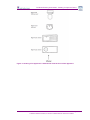


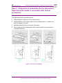

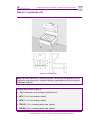
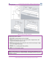


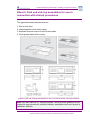
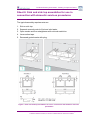
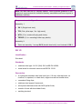


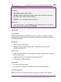
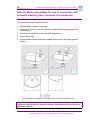
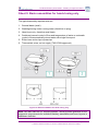

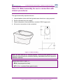

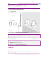


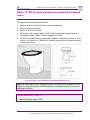
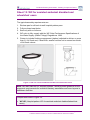


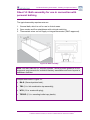
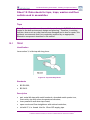
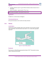

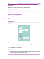

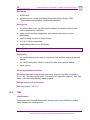
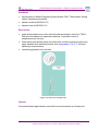
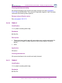
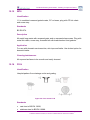


![MX2 sync [final].vp](http://vs1.manualzilla.com/store/data/005975841_1-4533d2555e3004ab9339335fb150c7a8-150x150.png)