1
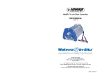
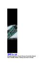
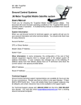
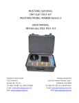
HYDROLIFT II INSTRUCTION MANUALHYDROLIFT II USER MANUAL
safety first
Stand clear of the HydroLift II when in use. The rapid up and down motion of
the drive shaft creates a potential hazard.
Always secure the pump to the well casing securely before starting the
pump, making sure that adequate clearance exists between the
reciprocating shaft and the well head. Never move the pump when
connected to a power source.
Use of electricity in wet areas creates a potential hazard and should be
avoided. Check the extension cord for defects prior to connecting to a power
source.
CAUTION
ALWAYS DISCONNECT POWER SUPPLY PRIOR TO PERFORMING ANY MAINTENANCE.
SPECIFICATIONS
Weight 35 lbs
Dimensions 14"H x 8"W x 24"L
Horsepower 3/4
RPM (maximum) 200
Power requirements
Pumping Instructions
Any standard generator with a 1000
watt output at 110 volts
Standard Flow System – 200 feet
High Flow System – 130 feet
Assembly & Operation
set-up
Hang the pump on the protective well head casing using the stainless steel hooks and secure tightly
with the ratcheting strap provided with the pump (not shown).
Release the cam lock assembly by lifting the cam lock lever upwards. Adjust the tubing clamp and
tubing so that it is centered over the well. Engage the cam lock assembly to maintain that position.
Check to see that the extension shaft is held securely by the cam lock assembly.
Lift the tubing in the well up through the tubing clamp and secure in place. Leave a sufficient length
(approx. 3 feet) of tubing to loop around and secure to the discharge tubing clamp located on the side
of the pump.
1
operation
Once the pump is secured to the casing and the tubing is properly set up, the Hydrolift II may be
plugged into the power source. Before proceeding, check to see that the speed control knob is
adjusted to the lowest speed. Turn the pump on and slowly adjust the speed control to the desired
setting.
NOTE: Select speed conservatively as faster cycle rates do not always translate into greater flow
rates.
The on/off rocker switch on the control panel also functions as a circuit breaker that will turn the unit
off in the event of electrical problems. The breaker is reset by turning the unit on again.
When not in use, the Hydrolift II should always be disconnected from the power source or turned off.
transport & storage
The Waterra Hydrolift II should always be transported in its original shipping container to ensure that
it is adequately protected during shipping. Replacement containers are available from Waterra.
Always store the Hydrolift II in an upright position to avoid leakage of the gearbox lubricant. Please
return the pump to Waterra if significant leakage occurs.
Routine Maintenance
1.Clean the outside of the pump with a wet cloth after every use. Store in a warm, dry place when not
in use to remove any moisture remaining on the electrical components.
2.Tighten any loose screws between use and check for any wear on critical components (i.e. rubber
boot, speed control knob, on/off switch, tubing clamps, and cam rake adjustment assembly).
3.Turn the pump on and adjust the speed to approximately 1/2 speed. Place your hand carefully on
the top of the rake adjustment assembly and press down to simulate a load. Observe the sound of the
pump under load to determine if any components are malfunctioning. The pump should be free of any
thumping or scraping noises when in use.
4.Occasionally lubricate the drive shaft by putting a few drops of gear oil (i.e. SAE 75 W-90) on the
drive shaft just above the central bushing. This process requires the partial removal of the rubber boot
to access the drive shaft/central bushing assembly.
2
Part
Sign of Wear
Drive Shaft
The drive shaft should oscillate
vertically. Any significant lateral
movement may indicate a problem.
Speed control knob
The speed control knob can normally
be rotated through 270 degrees. Any
larger movement may indicate a
failure.
Tubing clamps (top & side)
The tubing clamps should hold the
tubing firmly without slipping when in
motion. Check for loose fittings and
damaged components which may
impair performance.
Rubber boot
The rubber boot should be replaced
immediately if any crack or cut
appears on the boot. Debris on the
drive shaft may damage internal
bushings.
TROUBLESHOOTING
Problem
Check
Does not start – no power
1. Is the generator adequately
powered?
2. Has the on/off switch and
combination circuit breaker tripped?
3. Is the extension cord free of
defects?
4. Remove the top cover and
examine all electrical connections for
tightness.
Does not start – no power,
but fan is running
Problem is likely electrical or
mechanical. Please return to Waterra
for service.
Pump oscillates, but makes Problem is likely electrical or
loud rumbling or scraping mechanical. Please return to Waterra
for service.
noises
Rubber boot
The rubber boot should be replaced
immediately if any crack or cut
appears on the boot. Debris on the
drive shaft may damage internal
bushings.
3
Parts List
CLAMP ARM
CLEVIS PIN
RATCHET BELT
BELLOWS
4
Warranty Information
Waterra Pumps Limited warrants that each new Hydrolift II will be free, under normal use and
maintenance, from any defects in material or workmanship for the relevant warranty period.
Necessary repairs shall be made and replacement parts provided at no cost to the consumer when
Waterra acknowledges that such defects are attributable to faulty material or workmanship at the time
of manufacture. This warranty is not transferable.
warranty period
All components: 6 months
This warranty does not cover:
i) any repairs required as a result of collision, accident, striking an object, abuse, misuse, lack of
required maintenance or use of an incorrect power source;
ii) any repairs required as a result of any attachments, parts or devices installed or repairs done by a
party other than Waterra Pumps Limited;
iii) any Hydrolift II pumps modified, altered, disassembled or remodeled; and
iv) normal maintenance service such as: tightening screws, bolts or fittings, lubrication and engine
tune-up and the replacement of parts required for normal maintenance services including filters,
ignition points and condensers, spark plugs and wires, fuses, belts, lubricants and other expendables
susceptible to natural wear.
owner's obligation
The owner agrees to follow all safety procedures outlined with this equipment and follow the
maintenance schedule as indicated in the Owner's Manual. A record must be kept of regular
inspections and maintenance performed.
disclaimer
To the extent that the law permits, Waterra Pumps Limited disclaims any responsibility for the loss of
time or use of the Hydrolift II, transportation or towing costs or any other indirect, incidental or
consequential damage, inconvenience, commercial loss or personal injury. The warranty is not valid if
the product is not paid for in full within 60 days of the invoice date.
returning hydrolifts to waterra
Waterra requires that all customers notify Waterra prior to returning their Hydrolift II under the
Waterra warranty program. The Hydrolift will only be accepted if it has been thoroughly cleaned and
decontaminated. Hydrolifts must be properly packaged and all fuel must be removed from the pump
prior to shipping. Please contact Waterra in order to obtain a shipping address.
5
Contact Waterra
As of November 2002 Waterra can be reached as follows:
Canada and International
Waterra Pumps Limited
5200 Dixie Road, Unit 44
Mississauga, Ontario
CANADA L4W 1E4
voice: 905.238.5242
fax: 905.238.5704
email: [email protected]
United States
Waterra USA Inc.
715 West Orchard Drive, Suite 5
Bellingham, Washington
USA 98225
voice: 360.738.3366
fax: 360.738.3399
email: [email protected]
6