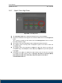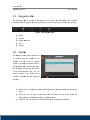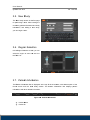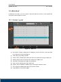
1
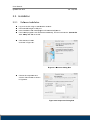
Userr Ma anua al Veterina Ve ary Accquisition and d diagn nostic softwa are D Doc No.: TM T -722-EN N R Rev 1.0.1 Aug A 2013 P Part No.: CR-FPM-04 C 4-022-EN 3DISC, FireCR, Quantor Q and d the 3D Cub be are tradem marks of 3D Imaging & S Simulations s Corp, South h Korea, and d its affiliates s. All other trrademarks arre held by th heir respectivve owners an nd are used in an editoriial fashion with w no intent ion of infring gement. The data in this publication are a for illustrration purposses only and d do not neccessarily rep present stand dards or speecifications, which must be met by 3D 3 Imaging & Simulatio ons Corp. All A information n contained herein is inte ended for gu uidance purp poses only, and a characte eristics of th he products and a servicess described in this publiccation can be b changed at any time e without no otice. Produc cts and servvices may not n be availa able in yourr local area. Please co ontact your local sales representatiive for availlability inform mation. 3D Imaging I & Simulations S s Corp. striv ves to provid de as accuraate information as possiible, but shalll not be resp ponsible for a any typograp phical error. © Co opyright 2010 0 3D Imagin ng & Simula tions Corp, all rights res served, printted, and pub blished in So outh Korea byy 3D Imaging & Simulattions Corp. Userr Manual Quan ntorVet Plus TM -72 22-EN Co ontact T g, Yuseong-G Gu, 815, Tamnip-Dong Daeje eon, Korea Tel : 82-42-931-21 8 100 Fax : 82-42-931-2 2299 site : www.3D DISCimaging g.com Webs E-mail : [email protected] com 3DISC C Americas 22560 0 Glenn Dr, S Suite 116 Sterlin ng, VA 20164 4 USA Tel : 1-703-430-60 1 080 E-mail : info@3DI SCimaging.c com 3DISC C Europe Gydevang, 39-41,, 3450 Allero oed, Denmark Tel : 45-88-276-65 4 50 E-mail : [email protected] com 2 Userr Manual Quan ntorVet Plus 22-EN TM -72 Warrnings and d used sym mbols To en nsure the saffety of patien nts, staff and other persons, any chan nges to softw ware and hardware Corp. may only delive ered by 3D Imaging I & Simulations S o be made with prior w written perm mission from 3D Imaging g & Simulatio ons Corp. Pleasse read the respective r manuals m of th he connected d devices, su uch as of thee X-ray gene erator, senso or, or reader,, before startting to use th he QuantorM Med+ softwarre. The ffollowing sym mbols will be used throug ghout this ma anual: DAN NGER The functionality f of the softw ware can be destroyed inn the case of incorrect use. If una authorized cchanges hav ve been mad de to delive red software e and hardware ccomponents, the warranty by 3D Imaging & Simu ulations Corrp. becomes s void. 3D Imaging I & Simulations s Corp p. will not acccept any responsibility or liability foor the proper functioning oh the e product in such s a case. DAN NGER Gene eral mandato ory action ma anual. The functionalityy of the syste em can be destroyed d inn the case of o incorrrect use. If una authorized cchanges have e been made e to deliveredd system and d acce essories, the warranty by y 3D Imagin ng & Simulaations Corp p. beco omes void. 3D Imaging g & Simulatio ons Corp. w will not accep pt any responsibility ty or liability for the imp proper functiioning of the e product in such a case. WAR RNING The functionalityy of the sys stem can be e limited in the case of o incorrect use. H Hints that require special attention. NOT TE Notes s represent i nformation that is important to know but which do o not afffect the funcctionality of the system. 3 User Manual QuantorVet Plus TM -722-EN Medical Device Security Users must take steps to secure their networks and protect their Medical Information Systems which includes a risk assessment strategy, network defense in depth strategy, business continuity planning, etc. User Authentication Only authorized users should log on to computers on which medical information systems are installed. Password Security In today’s world, passwords can be compromised in literally seconds by using a wide variety of tools and techniques. To lower the possibility of a compromised password, it is vital to adhere to a set of protocols. Choose a password between 7 ~ 10 characters using both alpha and numeric characters. Do not share the password. Do not base the password on a pet’s name, a relative’s name or any dictionary word. Do not write down the password. Do not leave the account logged on. User Access Control Configure the workstation to prompt for logon after coming out of stand-by mode. Internet Usage Accessing to the Internet exposes the computer to a plethora of vulnerabilities such as: Viruses Spyware Trojans Hostile Codes It is not recommended to install any unauthorized software on the computer. Peer-topeer software can expose your entire hard drive to any individual running the same type of software. Antivirus Products Use of antivirus software can increase CPU and memory usage, which can cause a slight degradation in the performance of the system. However, functionality should not be affected. Physical Security It is recommended that the user employs some method of physical security when dealing with the system to ensure that only authorized personnel have access to the product. 4 User Manual QuantorVet Plus TM -722-EN There are several vulnerabilities a malicious user could exploit locally. Some examples are: Theft of equipment Local password cracking Installation of hardware key loggers 5 User Manual QuantorVet Plus TM -722-EN Table of contents 1. Introduction ................................................................................ 10 1.1. Main Features..................................................................................11 2. Installation ................................................................................. 12 2.1. 2.2. Environment ................................................................................... 12 2.1.1. Recommended Computer Requirement ........................................................ 12 2.1.2. Minimum Computer Requirement .................................................................. 12 Installation ...................................................................................... 13 2.2.1. 2.3. 2.4. Software Installation ....................................................................................... 13 Start and Termination ..................................................................... 17 2.3.1. System Start ................................................................................................... 17 2.3.2. Start Program ................................................................................................. 17 2.3.3. Terminate Program ......................................................................................... 18 FireCR Calibration.......................................................................... 19 2.4.1. Calibration Geometry ..................................................................................... 21 2.4.2. Step 1: Auto Alignment ................................................................................... 22 2.4.3. Step 2: Erase .................................................................................................. 22 2.4.4. Step 3: Scan Blank ......................................................................................... 23 2.4.5. Step 4: Scan Low Dose .................................................................................. 24 2.4.6. Step 5: Scan Mid Dose ................................................................................... 25 2.4.7. Step 6: Scan High Dose ................................................................................. 26 2.4.8. Step 7: Calibration! ......................................................................................... 27 2.4.9. Step 8: Cancel ................................................................................................ 27 2.4.10. Note ................................................................................................................ 28 3. Screens ..................................................................................... 30 3.1. 3.2. 3.3. 3.4. 3.5. 3.6. 3.7. 3.8. 3.9. Supported Resolutions ................................................................... 30 Home .............................................................................................. 30 Navigation Bar ................................................................................ 31 Studies ........................................................................................... 31 New Study ...................................................................................... 32 Region Selection ............................................................................ 32 Patient Information ......................................................................... 32 Scan ............................................................................................... 33 Review ............................................................................................ 33 4. Home Window ........................................................................... 34 6 User Manual QuantorVet Plus 4.1. 4.2. TM -722-EN Screen Layout ................................................................................ 34 System Menu.................................................................................. 35 5. New Study ................................................................................. 36 5.1. 5.2. Screen Layout ................................................................................ 36 Input Field Edit Dialog Box ............................................................. 38 6. Region Selection ....................................................................... 39 6.1. 6.2. Screen Layout ................................................................................ 39 Body Parts and View Positions ....................................................... 40 7. Scan .......................................................................................... 42 7.1. 7.2. 7.3. Screen Layout ................................................................................ 42 Exposure Input ............................................................................... 43 Cassette Indicator........................................................................... 43 8. Image......................................................................................... 44 8.1. 8.2. 8.3. 8.4. 8.5. 8.6. 8.7. 8.8. 8.9. 8.10. 8.11. Screen Layout ................................................................................ 44 ROI ................................................................................................. 45 Marking ........................................................................................... 45 Rotate/Flip ...................................................................................... 46 Auto Window .................................................................................. 47 Retake ............................................................................................ 47 Reject ............................................................................................. 47 QA – LUT Curve ............................................................................. 48 QA – Image Processing Filters ....................................................... 49 Send Image .................................................................................... 50 Exposure Index............................................................................... 51 9. Task List..................................................................................... 52 9.1. Screen Layout ................................................................................ 52 9.2. 9.3. Stitch .............................................................................................. 53 Print ................................................................................................ 55 10. Review ....................................................................................... 57 10.1. 10.2. 10.3. 10.4. 10.5. 10.6. 10.7. Screen Layout ................................................................................ 57 View Caption Bar ............................................................................ 58 Full Screen ..................................................................................... 59 Image Manipulation ........................................................................ 60 Measurement ................................................................................. 60 Marking ........................................................................................... 63 File.................................................................................................. 64 7 User Manual QuantorVet Plus 10.8. 10.9. TM -722-EN Tools ............................................................................................... 64 Apply Range ................................................................................... 65 11. Study List ................................................................................... 66 11.1. 11.2. 11.3. 11.4. 11.5. Screen Layout ................................................................................ 66 List .................................................................................................. 67 Edit Column .................................................................................... 68 Search ............................................................................................ 69 Export ............................................................................................. 69 12. Work List .................................................................................... 71 12.1. 12.2. Screen Layout ................................................................................ 71 List .................................................................................................. 72 13. Transport ................................................................................... 73 13.1. 13.2. Screen Layout ................................................................................ 73 List .................................................................................................. 73 14. Settings...................................................................................... 75 14.1. Screen Layout ................................................................................ 75 14.2. General ........................................................................................... 75 14.2.1. Option ............................................................................................. 75 14.2.2. User Information ............................................................................. 76 14.2.3. Password for Processing Parameter .............................................. 76 14.2.4. Display Language ........................................................................... 76 14.3. Fonts .............................................................................................. 76 14.3.1. Common ......................................................................................... 76 14.3.2. Marking ........................................................................................... 77 14.3.3. Printer ............................................................................................. 77 14.4. Network/Export ............................................................................... 78 14.4.1. Image Server .................................................................................. 78 14.4.2. Work List Server ............................................................................. 79 14.4.3. DICOM Printer ................................................................................ 79 14.4.4. Options ........................................................................................... 80 14.5. Work List ........................................................................................ 81 14.5.1. Work List ........................................................................................ 81 14.6. Overlay ........................................................................................... 81 14.6.1. Marking ........................................................................................... 81 14.6.2. Auto Mark Margin ........................................................................... 81 14.6.3. Print Overlay Contents ................................................................... 82 8 User Manual QuantorVet Plus TM -722-EN 14.7. System ........................................................................................... 82 14.7.1. Exposure Input ............................................................................... 82 14.7.2. File Management ............................................................................ 82 14.7.3. System Options .............................................................................. 83 14.7.4. Date ................................................................................................ 83 9 User Manual QuantorVet Plus TM -722-EN 1. Introduction QuantorVet+ is intuitive, easy-to-use workstation software that provides facilities using 3D Imaging & Simulations Corp. CR readers with optimized image acquisition, processing, and management capabilities. Its DICOM compliant interface allows for simple integration into a facility’s HIS, RIS, and PACS, providing the full range of capabilities needed for improved productivity and workflow in busy clinics and practices. This user manual provides detailed information about the operation of QuantorVet+ and the use of the range of facilities included in the software to make the processing and administration of your medical X-ray images as efficient as possible. Safety Instruction To ensure the safety of patients, staff and other persons, any changes to software and hardware delivered by 3D Imaging & Simulations Corp. may only be made with prior written permission from 3D Imaging & Simulations Corp. Liability If unauthorized changes have been made to delivered software and hardware components, the warranty by 3D Imaging & Simulations Corp. becomes void. 3D Imaging & Simulations Corp. will not accept any responsibility or liability for the improper functioning of the product in such a case. QuantorVet+ is not approved for the acquisition of mammographic image data. 10 User Manual QuantorVet Plus TM -722-EN 1.1. Main Features Image Acquisition & Study Management QuantorVet+ Software allows facilities to quickly input patient data – or access it directly from their HIS, RIS or PACS for improved productivity and accuracy. Image acquisition is supported by a fully developed list of exams and anatomies, and a viewer displays images on a monitor to facilitate quality control and image management. Once completed, the study can be sent to the PACS, printed on a dry film printer, or burned onto a CD or DVD. Image Manipulation, Multi-Viewing & Stitching To optimize images, technicians can crop, etch, enhance, increase brightness and contrast, and perform other adjustments. Regions of interest can be highlighted, and users can easily change the order of images or delete images in the multi-view window. Stitching capabilities for images of legs, spines, and other anatomical areas are particularly useful for orthopedic and chiropractic facilities. Integrated Viewer For smaller facilities without a HIS, RIS or PACS, QuantorVet+’s local database enables direct management of patients and studies utilizing a unique viewer function. Technicians and radiologists can review DICOM and non-DICOM images on the same station they acquired it on. Full Range of Output Options QuantorVet+ features a full range of output options, including DICOM CD-burn, embedded view, DICOM send SCU, and DICOM print for dry film printers. The combined DICOM Patient CD and dry film print creates patient CD / DVDs that include DICOM DIR structure and a built-in viewer. 11 User Manual QuantorVet Plus TM -722-EN 2. Installation 2.1. Environment 2.1.1. Recommended Computer Requirement Operating System CPU Memory Microsoft Windows 7, 8 Intel CORE i5 RAM 4 GB or more Hard Disk 500 GB Free Hard Disk Space Network Video Video Resolution 1 Gbps Ethernet 32-bit Color Display 1920 x 1080, 1440 x 900 2.1.2. Minimum Computer Requirement Operating System CPU Memory Microsoft Windows XP Intel Processor RAM 2 GB or more Hard Disk 80 GB Free Hard Disk Space Network Video Video Resolution 1 Gbps Ethernet 32-bit Color Display 1366 x 768, 1280 x 800, 1600 x 900, 1280 x 1024 12 Userr Manual Quan ntorVet Plus TM -72 22-EN 2.2. Installlation 2.2.1. Softw ware Insttallation Log on to t the PC using an admin nistrator acco ount. Connectt USB Dongle to USB po rt. Insert Installation CD D. Install prog gram will auttomatically la aunch. If the insstall program m is not launcched automa atically, find and executee the “QuanttorVet 2.x.x. Se etup.exe” file e on the CD.. Click the e “Next” butto on as show wn in Figure 2.1. 2 Figure F 2.1 Welcome W Diaalog Box Choose all compone ents and click the "Next" butto on as shown in Figure e 2.2. F Figure 2.2 Component C ts Dialog Bo ox 13 Userr Manual Quan ntorVet Plus TM -72 22-EN Choose your langua age and clicck the "Nexxt" button as shown in Figure e 2.3. omponents D Dialog Box Fiigure 2.3 Co Choose the destinatiion folder and clickk the "Install"" button as show wn in Figure 2.4. 2 Figure e 2.4 Installation Locationn Dialog Box x 14 Userr Manual Quan ntorVet Plus TM -72 22-EN Installation status will be displaye ed as shown in Figure e 2.5. Fiigure 2.5 Ins stall Status D Dialog Box Installation status of the Dongle Driver will w be display yed as Shown in Figure 2.6 Fig gure 2.6. Installation of d ongle Driverr Installation status of o the FireC CR USB drivver will be dis splayed as Shown in Figure 2.7 gure 2.7. Installation of F FireCR USB Driver Fig 15 Userr Manual Quan ntorVet Plus TM -72 22-EN If installa ation is succe essful, Figure 2.8 2 will show up. Click "Finish" to finish the insta allation. F igure 2.8 Installation Finnish Dialog Box B If the Windows W Se ecurity Dialo og Box pop ps up after ins stallation, click [Allow access]. gure 2.9. Win ndows Securrity Dialog Bo ox Fig 16 Userr Manual TM -72 22-EN Quan ntorVet Plus 2.3. Start and a Term mination n 2.3.1. Systtem Startt 1 1. Turn on the t FireCR CR C Reader. 2 2. Turn on the t monitor and a PC. WARNING Do not n run anyy application n software other than QuantorVett+ durin ng operation n of the sc canner. This may slow the scanne er respo onse. 2.3.2. Start rt Program m After Windows iss successfully booted, yyou can laun nch the Qua antorVet+ prrogram by double d clickin ng the Quan ntorVet+ icon n on your dessktop as sho own in figure 2.11. Figure 2.10. Home Window QuantorVet+ C Icon Figure 2.11. Short Cut 17 Userr Manual TM -72 22-EN Quan ntorVet Plus 2.3.3. Term minate Prrogram Selecct the System m button as shown s in Fig ure 2.12 on the t Home Window. W Figure 2.12. System m Button Now you can exit the application by selectting "Exit" in the System Menu. Figure 2.13. System m Menu 18 Userr Manual Quan ntorVet Plus TM -72 22-EN 2.4. FireC CR Calibrration Selecct IP Calibra ation in the System S Men nu, then the following wiindow will poop up. Follo ow the stepss in the menu u. WAR RNING Calibrrate the scan nner before use. The “P Please calibrrate system”” messa age pops up if the scanner is not calib brated or callibration data a does not n exist. It is re ecommended d to calibrate e the reader after movingg it and as a part off regular maiintenance. Figure e 2.14. IP Calibration WAR RNING Calibrration shoulld be done e for both a Universsal Cassette e contaiining IP 14” x 17” and a Universal Ca assette contaaining IP 10”” x 12”. 19 User Manual QuantorVet Plus TM -722-EN Name Auto Alignment Erase Scan Blank Description Alignment of laser beam position. Erase IP. Create the first calibration image file. Scan Low Dose Create the second calibration image file. Scan Mid Dose Create the third calibration image file. Scan High Dose Create the fourth calibration image file. Calibration Cancel Cassette Size Create a calibration data file. After a successful calibration the calibration window will automatically close. Close the IP Calibration window. This will abort the current calibration. Select the IP size for calibration. Accept a calibration image file. The Accept Accept button is displayed to accept calibration image files with values out of range. Reject a calibration image file. The Reject Reject button is displayed to reject calibration image files with values out of range. 20 Userr Manual Quan ntorVet Plus 2.4.1. TM -72 22-EN Calib bration Geometry G Figure 2.1 5. Calibration Geometry WAR RNING X-ray radiation fie ld must cove er the whole area of the ccassette. 21 Userr Manual Quan ntorVet Plus 2.4.2. TM -72 22-EN Step p 1: Auto Alignmen A nt Figure 2 2.16. Auto Alignment A 2.4.3. Perform Auto Alignment before e starting ca alibration to find the opptimal laser beam position.. Step p 2: Erase e Fig gure 2.17. Errase The Erasse button is enabled whe en the cassette is inserted to the readder. It erasess the cassette e before cali bration. 22 Userr Manual Quan ntorVet Plus 2.4.4. TM -72 22-EN Step p 3: Scan Blank Figure e 2.18. Scan n Blank The Sca an Blank buttton is enable ed after perfo orming the Erase E step. After the e Erase step p, insert the cassette witth no X-ray exposure intto the reade er and click Sca an Blank to acquire the ffirst calibratio on image. The mea an intensity value v of the b blank image is displayed beneath thee button. The mea an intensity value v of the blank image e is displayed d in green if tthe value is within the acce eptable range e. The mea an intensity value v of the b blank image is displayed in red if the value is not within the acce eptable range e. If the mean m intensitty value of tthe blank im mage is displayed in redd, click Acce ept to continue e anyways orr Reject to trry again. To lowerr the mean in ntensity value e of the blank image, clic ck Erase agaain. 23 Userr Manual Quan ntorVet Plus 2.4.5. TM -72 22-EN Step p 4: Scan Low Dosse Figure 2 2.19. Scan Low L Dose The Sca an Low Dose e button is en nabled after performing a Scan Blan nk. Expose the cassette e to the X-rayy with the co onditions note ed below thee Scan Low Dose button. Then, in nsert the cas ssette into tthe reader and a click Scan Low Dos ose to acquire the second calibration c im mage. The mea an intensity value v of the l ow dose ima age is display yed beneath the button. The mea an intensity value v of the llow dose is displayed d in green if the value is with hin the acceptab ble range. The mea an intensity value of the low dose is s displayed in n red if the vvalue is not within the acce eptable range e, click Acce ept to continu ue anyways or o Reject to try again. Increase e the X-ray dose d to incre ease the mea an intensity value or low wer the X-ray y dose to decre ease the me ean intensity value. *If changes c are e made to ttechnique (D Dose) please note n the new w values use ed (KVp, mA As) and inpu ut the new d data in C:\Quan ntorMed+\firrecr.ini 24 Userr Manual Quan ntorVet Plus 2.4.6. TM -72 22-EN Step p 5: Scan Mid Dosse Figure 2 2.20. Scan Mid M Dose The Sca an Mid Dose button is ena abled after performing p a Scan Low D Dose. Expose the cassette e to the X-rayy with the co onditions notted below thee Scan Mid Dose button. Then, in nsert the cas ssette into th he reader an nd click Scan n Mid Dose button to ac cquire the third calibration image. The mea an intensity value v of the m mid dose ima age is displayed beneathh the button. The mea an intensity value of the e mid dose is displayed in green if tthe value is within acceptab ble range. The mea an intensity value of the mid dose is s displayed in red if the vvalue is not within the acce eptable range, click Acce ept to contin nue anyways s or Reject tto acquire th he mid dose ima age again. Increase e the X-ray dose d to incre ease the mea an intensity value or low wer the X-ray y dose to decrease the mea an intensity vvalue. 25 Userr Manual Quan ntorVet Plus 2.4.7. TM -72 22-EN Step p 6: Scan High Do ose Figure 2 2.21. Scan High H Dose Dose. The Sca an High Dos se button is e enabled afterr performing a Scan Mid D Expose the cassette e to the X-rayy with the conditions note ed below thee Scan High Dose button. Then, in nsert the cassette into the d click Scan n High Dosee button to acquire e reader and the fourtth calibration image. The intensity value of o the high do ose image is displayed beneath the bbutton. The inte ensity value of the high dose is displayed in grreen if the vvalue is within the acceptab ble range. dose is disp The inte ensity value of the high d played in red d if the valuee is not with hin the acceptab ble range, click Accept to o continue anyways a or Reject R to acqquire the high h dose image ag gain. Increase e the X-ray dose d to incre ease the mea an intensity value or low wer the X-ray y dose to decre ease the me ean intensity value. *If changes c are e made to ttechnique (D Dose) please note n the new w values use ed (KVp, mA As) and inpu ut the new d data in C:\Quan ntorMed+\firrecr.ini 26 Userr Manual Quan ntorVet Plus 2.4.8. TM -72 22-EN Step p 7: Calibration! Figurre 2.22. Calib bration 2.4.9. The Cali libration buttton is enable ed after perfo orming a successful Scann High Dose.. Click the e Calibration n button to g generate callibration data a. Calibrationn data is sav ved in your loca al program fo older. After gen neration of calibration da ata, the calibrration window w closes autoomatically. Step p 8: Canc cel You can n exit calibrattion window in the middle of process. This will aabort your current c calibratio on process. 27 Userr Manual Quan ntorVet Plus TM -72 22-EN 2.4.10. Note e When th he mean inte ensity value for each ste ep is within acceptable range, value es are shown in n green. Figure 2..23. Proper Calibration C When th he mean intensity value fo or each step p is not within n acceptable range, value es are shown in n red. Figure 2.2 24. Improper Calibration Start the e calibration process fro om Auto Aliignment or Erase for reecalibration of the reader. 28 Userr Manual Quan ntorVet Plus TM -72 22-EN NOTE E Following the calibrration proces ss, two sets of four imagees used for calibrattion and two calibration files f are generated in loccal program folder. 29 Userr Manual Quan ntorVet Plus TM -72 22-EN 3. Screen ns 3.1. Suppo orted Re esolution ns Landscape resolutions with 16:9, 4:3 a and 5:4 ratio os are supp ported. Portrrait ratios arre not suppo orted. The horizontal resolution of the e monitor mu ust be at leas st 1280 pixells, and the vertical resolu ution of the monitor mus st be at leasst 768 pixels s. Recomme ended resoluutions are lis sted in Table e 3.1. Table 3.1 S Screen Ratio o Sc creen Resoluution 1366 x 7688 1280 x 8000 1400 x 9000 16:9 1600 x 9000 1920 x 10800 4:3, 5:4 1280 x 10244 3.2. Home e The H Home screen n is the first screen s that appears when the e program is s run. From the H Home screen, you can cre eate a new studyy or view exissting studies. Figure 3.1. Home Sccreen 30 Userr Manual Quan ntorVet Plus TM -72 22-EN 3.3. Navig gation Ba ar The Navigation Bar B is located at the b bottom of the screen. The T Navigatioon Bar is always a displa ayed while th he program is s running, al lowing the user to easily switch screeens during a task. ② ① ③ ④ ⑤ Figure 3.2. Navigattion Bar ① Home ② Studies ③ Region Selection S ④ Scan ⑤ Review 3.4. Studie es The S Studies scre een shows a collection of w windows that are relate ed to the studie es. You ca an enter the Studies ① ② ③ scree en by clicking g the Studies button in the N Navigation Ba ar. The Sub-Navigation Bar iss located on n the left of the screen. In th he Sub-Navigation Bar, you can selecct a Study List, Work List or Transsport window ws that are related to the sttudy. ① Figure 3.3. Studies Sccreen Study List: You can perform p vario ous tasks by y searching existing e studiees and selec cting a study. ② Work List: You can query the w work list fro om the PACS S work list server, select the s and im mmediately be egin image acquisition. a desired study ③ Transport: You can confirm c the trransmission results of the e acquired im mages. ① ③ 31 Userr Manual Quan ntorVet Plus TM -72 22-EN 3.5. New Study S The N New Study screen s is the e first page for pe erforming a scan. s After entering the necesssary patientt information n and study inform mation, and adding a new n study, you ccan begin a scan. s Figure 3.4. 3 New Stu udy 3.6. Regio on Selec ction In the e Region Sellection scree en, you can selecct the region to scan and d add it to the Ta Task List. Figure 3.5. Region R Seleection 3.7. Patien nt Inform mation The P Patient Inform mation Bar is displayed at the top off all the scre eens, with thee exception of the Home e screen and the New w Study scrreen. The Patient P Inforrmation Barr displays patient p inform mation and other o related information. ① ② ③ ④ ⑤ ⑥ 6. Patient In nformation Figure 3.6 ① Patient Name N ② Patient ID 32 ⑦ ⑧ Userr Manual Quan ntorVet Plus 22-EN TM -72 ③ Patient'ss Date of Birtth ④ Patient'ss Age ⑤ Patient'ss Sex (M: Ma ale, F: Fema ale, O: Otherr, SM: Sterile e Male, SF: S Sterile Fema ale, S: Sterile) ⑥ Current Time ⑦ Model Name N ⑧ System 3.8. Scan In the e Scan scre een, you can insert a casse ette into the e FireCR an nd acquire image es. Figure 3.7 7. Scan Screeen 3.9. Revie ew In the e Review sccreen, you can query scann ned image es in the identical mann ner as the PACS Vie ewer. The Revie ew screen is very useful u for condu ucting diagnosis after acquiring the im mages. Figure 3.8 8. Review S Screen 33 Userr Manual Quan ntorVet Plus TM -72 22-EN 4. Home Windo ow 4.1. Scree en Layou ut The H Home scree en is the firstt screen tha at appears when w the pro ogram is runn. From the Home scree en, you can create a ne ew study or view existing g studies. You Y can go bback to the Home scree en by using one o of the ac ctions below. Clicking the Home button in the N Navigation Bar B Clicking the End Study button in the Scan screen Clicking the End Study button in the Review screen s ① ② ④ ⑤ ⑥ W Figure 4.1. Home Window ① Model Name: N Displays the mode el name of FiireCR. ② Current Time: Curren nt time is dissplayed in ho ours and minu utes. ③ System: Displays the e System me enu. ④ Create New N Study: Go G to New Sttudy screen. ⑤ Study List: Go to Stu udy List scree en. ⑥ n. Work Lisst: Go to Worrk List screen 34 ③ Userr Manual Quan ntorVet Plus 22-EN TM -72 4.2. System Menu u The S System buttton is always displayed in the uppe er-right corne er of the pro rogram. Whe en the button is clicked, the following g menu appe ears on the screen. Figure e 4.2. System m Menu Settings: Displays the Settings w window. IP Calibrration: Runs IP Calibratio on program. Scannerr Control: Runs Scanner Control prog gram. Check Update: U Checks for a new versio on. If a new w version iis available, it is automattically downlo oaded and in nstalled. Exit: Exits the progra am. 35 Userr Manual Quan ntorVet Plus TM -72 22-EN 5. New Study S 5.1. Scree en Layou ut The N New Study screen s is the e first page w when perforrming a scan n. Enter the necessary patient p and sstudy informa ation. You ca an easily sw itch to the ne ext input field by using thhe Tab key. Fields marked by * are mandatory m DICOM fields that must be e filled in. ① ③ ② ④ ⑤ ⑥ Figurre 5.1. New Study ① Emergen ncy: Mandatory fields a are filled in automatica ally. This funnction is us sed in emergen ncies where patient inforrmation has not been ide entified to peerform a sca an first and fill in n the patient data later. ② Edit Inpu ut Field: Brin ng up Input F Field Edit dia alog. In the In nput Field Eddit dialog, yo ou can change the t order of the t input field ds, and add or remove in nput fields. ③ System Menu: Displa ay the Syste em menu. ④ Input Fie eld: Details about a each in nput field are e described in n Table 5.1. Table e 5.1. Input Field Title e Descriptio on Mand datory Nam me Enter pattient name. O 36 User Manual QuantorVet Plus ID TM -722-EN Enter patient ID. O Enter patient’s date of birth. You can select a date from the drop-down box or manually enter numbers. When only the Birth date of birth is entered and not the age, age is calculated O automatically. Select patient’s sex. Sex (Male, Female, NA, Sterile Male, Sterile Female, Sterile) O Enter patient’s age. Leave the Year field blank if the patient is less than 1 year old. When only the age is entered and not the Age date of birth, date of birth is calculated automatically. When it X does, month and date are automatically entered as January 1. Ref. Physician Enter the name of the referring physician. X Description Enter study description. X Enter accession number. Entering an accession number is Accession No. mandatory. If not entered, a new number will be generated O automatically. Size Enter patient length. Species X Select patient species. (Dog, Cat, Rabbit, Small Rodent, Bird, Exotics, Horse, Cow) X Breed Enter patient breed. X Owner Enter patient owner. X Page Up/Down: Go to another page. Next: Go to the Region Selection screen, which is the next step. 37 Userr Manual Quan ntorVet Plus TM -72 22-EN 5.2. Input Field Ed dit Dialog Box In the e Input Field d Edit dialog g box, you ccan change the order of the input ffields, and add a or remo ove input fie elds. The input fields ccan be edite ed according g to the usser’s environ nment. Howe ever, mandattory input fields cannot be e removed. ① ② ③ ⑤ ④ ⑥ ⑦ ⑧ Figure 5.2. Input Fiield Edit ① Input field items to be displayed o on the scree en. ② Input field items not to t be displayyed on the sc creen. ③ Move se elected items s to left and rright. Items on o the left are displayed oon the scree en and the itemss on the right are not disp played on the screen. ④ Button fo or switching pages. ⑤ Move the e selected ite ems up or do own on the list to change e order. ⑥ Save changes and close c the dial og box. ⑦ Cancel changes c and d close the diialog box. ⑧ Reset th he fields to de efault setting gs. 38 Userr Manual Quan ntorVet Plus TM -72 22-EN 6. Region n Selec ction 6.1. Scree en Layou ut In the e Region Selection scree en, you can sselect the reg gion to scan and add it too the Task Lis st. ③ ⑥ ① ④ ② ⑤ ⑦ ⑧ Figure 6 6.1. Region Selection S ① Body Pa art: The regio on to be scan nned will be displayed on n the figure oof the animal body. When yo ou move the e mouse currsor over the e figure, the region to bee selected will w be marked by a differen nt color. Sele ect the desire ed region and d the View P Position List will w be updated. ② Species: Change th he species. You can’t use u this fun nction after adding first View Position ③ View Po osition: Displays view po ositions thatt correspond d with the seelected regio on for scanning g. Click on th he region to sscan and the e region will be b added to the Task Listt. ④ Preset: Displays D view w position p presets. Whe en a certain setting s is useed frequently, you can eassily automatic cally add mu ultiple view positions by selecting a preset inste ead of adding separate s view w positions e each time. ⑤ Page Up p/Down: Buttton for switch hing pages. ⑥ Task List: List of view w positions a added from View V Position or Preset fieelds. 39 User Manual QuantorVet Plus TM -722-EN ⑦ Previous: Go back to New Study screen. ⑧ Next: Proceed to Scan screen. 6.2. Body Parts and View Positions The body parts and view positions provided in the product by default are listed in Table 6.1. Table 6.1. View Position Species Body Part View Position Dog, Abdomen Lateral Cat, Rabbit, AP Skull Lateral Small Rodent AP Pelvis Lateral AP Thorax Lateral AP Extremity Lateral AP Bird Chest Lateral AP Wing Lateral AP Exotics Snake Lateral AP Lizard Lateral AP Frog Lateral AP Turtle Lateral AP Horse, Cannon Bone and Splints Lateral Cow Medial AP/Dorsal Fetlock Lateral Dorsoplantar 40 User Manual QuantorVet Plus TM -722-EN Lateral Oblique Medial Oblique Knee Lateral Dorsal Lateral Oblique Medial Oblique Stifle Lateral Elbow Lateral Hock Dorsoplantar Lateral Lateral Oblique Medial Oblique Mandible Lateral 41 Userr Manual Quan ntorVet Plus TM -72 22-EN 7. Scan 7.1. Scree en Layou ut In the e Scan scree en, you can in nsert a casse ette into the FireCR and acquire imagges. ④ ⑥ ① ② ③ ⑤ ⑦ ⑧ gure 7.1. Sc Fig can ① Scan: Be egin a scan. ② Stop: Sto op a scan. ③ Erase: Erase E the IP P. By defaullt, the IP is deleted auttomatically aafter a scan. This function is only used to manuallyy delete the IP. ④ Progresss: The scann ning progresss is shown in n a circle and d in percentaages. ⑤ Resolution: Select th he scan reso olution. HD resolution sc cans with 1000 mm pixel pitch, s at 200 0 mm pixel pitch. Lowe er pixel pitchh results in higher h and SD resolution scans on images. resolutio ⑥ Cassette e Indicator: Displays D the sstatus of the e cassette. ⑦ Exposurre Input: Ente er the X-ray e exposure settings. ⑧ Model Name: N Displays the mode el name of FiireCR connected to the P PC. 42 Userr Manual Quan ntorVet Plus TM -72 22-EN 7.2. Expossure Input Enterr the X-ray exposure e setttings. Expossure Input fie eld is only activated a wheen it is enab bled in [System – Expossure Input]. The T entered values will be b included in the DICO OM informatio on. As show wn in Table 7..1, 4 types ca an be entere ed. Table 7 7.1. Exposurre Input Type kVp p mA ms mAs 1 O O O Calculate ed automatically 2 O X X O 3 O O Calc culated O autom matically 4 O Calculated O O a automatically y 7.3. Casse ette Indicator The C Cassette Indicator display ys whether t he cassette is inserted and recognizeed correctly. 2. Cassette Indicator Table 7.2 Status Indicator A cassette is not inserte ed. A cassette is inserted, but cassette size informa ation is not reecognized. A cassette e is inserted d, cassette size informa ation is recoognized, butt the current size e has not be een calibrated d. The status is okay and ready for sc can. 43 Userr Manual Quan ntorVet Plus TM -72 22-EN 8. Image e 8.1. Scree en Layou ut When n an IP scan n has been completed, th he acquired image is disp played on thee Scan window as show wn in Figure 8.1. 8 ② ③ ① ④ ⑤ ⑥ ⑦ ⑧ ⑨ ⑩ ⑪ Fig gure 8.1. Ima age ① ROI Boxx: A tool for cropping the vvalid region of o the scanned image. ② ROI: RO OI-related too ols ③ Marking: Add markin ngs on the im mage. ④ Rotate Flip: F Rotate/fllip the image e. ⑤ Auto Win ndow: Autom matically adju ust the image e brightness and contrastt. ⑥ Repeat: Scan the image again. ⑦ Reject: Reject R the im mage. ⑧ QA: Brin ng up tools fo or adjusting i mage details s. ⑨ Send Im mage: Transm mit the image e. ⑩ Image Comment: C Wrrite image co omment ⑪ Exposurre Index: Sho ow the expossure index va alue of the sc canned imagge. 44 Userr Manual Quan ntorVet Plus TM -72 22-EN 8.2. ROI When n a scan is completed, c the image is displayed and the ROI Box of the ppredefined siize for each scanned reg gion is autom matically disp played as sho own in Figurre 8.1. Whenn you drag the ROI Box tto the desire ed location an nd double-cl ick the ROI Box or click on the ROI button, the ROI R is cropp ped and fitted d to the scre een as shown n in Figure 8.2. 8 To adjustt the size of tthe ROI Box x, drag the sm mall rectangles at each corner c of the ROI. When transmitting or printing thhe image, on nly the ROI a are used. 2. ROI Cropp ped Image Figure 8.2 To brring up the ROI R Box again, double-cliick on the im mage or click on the ROI button. Whe en you click on the ROI button, the film f sizes lissted below will w be display yed on the sscreen. Whe en you selecct one of the given sizes, the ROI Boxx will be adjusted to that size. s 8 x 10, 10 x 12, 14 x 14 , 14 x 17, 10 0 x 8, 12 x 10 0, 17 x 14 8.3. Markin ng The Marking featture is used d to add ma arkings on th he image. Markings M cann be added to the image e by selectin ng a predefined marking o or manually typing t in textt. 45 Userr Manual Quan ntorVet Plus TM -72 22-EN Add Predefined Markings Click on the Marking M button. ① C ③ ② ① ② S Select a marrking. ③ C Click on the image. i Prede efined markkings can be edited in Settin ngs under [O Overlay-Marking]. Fig gure 8.3. Ad dd Predefineed Markings s ually Enter Markings M Manu ① C Click on the Marking M button. ① ③ ② S Select Directt Input. ② ③ C Click on the position wh here you wa ant tto add the marking m and d a text inp put b box will appe ear. Enter yo our text. Clicck o outside the text input box b when yo ou a are done. Fig gure 8.4. Ma anually Enteer Markings 8.4. Rotate e/Flip Used d to rotate or flip images. Icon Action Rotate R Left Rotate R Right Flip F Horizonta ally 46 Userr Manual Quan ntorVet Plus TM -72 22-EN Flip F Verticallyy 8.5. Auto Window W w Autom matically adjust the image brightnesss and contras st. 8.6. Retakke Used d when the quality q of the e scanned im mage is insuffficient and requires r a reescan. Reme ember that the current im mage will be deleted. 8.7. Rejecct When n the quality of the scann ned image iss insufficient, Reject prese erves the cu rrent image with a Reject’ mark “Reje ect” marking without resc canning. Wh hen the Reje ect button is clicked, a “R king is added on the upp per left corne er of the imag ge as shown below, and a “Reason” iinput field ap ppears on th he screen. Tyype in the re eason for rejjection, and click outside e the input bbox when yo ou are done. You can ca ancel a rejecttion by clickin ng the Rejec ct button again. Fig gure 8.5. Rejject 47 Userr Manual Quan ntorVet Plus TM -72 22-EN 8.8. QA – LUT Cu urve Used d to adjust th he LUT Curv ve of the im mage. Adjusting the imag ge requires expert know wledge aboutt images. Ad djusting the im mage withou ut proper kno owledge may result in low wer image qu uality. ① ④ ⑤ ⑥ ② ③ ⑦ C Figurre 8.6. LUT Curve LUT Curve: LUT curve applied a to th e image. A default curve e for each re region is provided. ① L T The user can n adjust the curve to the eir preferenc ce. To adjust the curve, sset a controll point a and drag the e curve using g the mouse.. To add a ne ew control po oint, click onn the line usin ng the m mouse. A con ntrol point ca an be remove ed by dragging it outside the box. ② H Histogram: Shows S the histogram of th gion at the ceenter is the region r he image. The bright reg ccurrently disp played on th he screen. T The left part of the histo ogram indicaates the frequency w where X-ray penetration level is low w and image is bright. The right partt of the histo ogram indicates the e frequency where w X-rayy penetration n level is hig gh and imag e is dark. Im mages h have low pixe el values in bright b regionss and high pixel p values in n dark regionns. ③ W Window Cen nter / Width: Used to ad djust the win ndow center and width oof the image e. The w window centter is adjuste ed when yo ou drag the image up or down, andd window wiidth is a adjusted whe en you drag the image le eft or right. Dragging D the sliders has tthe same effect as d dragging the image. 48 Userr Manual Quan ntorVet Plus TM -72 22-EN Window Width W W Window Centerr Set: Set the curve c and wiindow value adjusted by the user as the default vvalue for imag ges of ④ S tthe current re egion. ⑤ L Load: Load and a apply default curves and window values of the current reggion. ⑥ R Reset: Resett curve. ⑦ P Processing: Go G to Image Processing Filters scree en. 8.9. QA – Image Processi P ing Filte ers Used d to adjust im mage proces ssing filters. A Adjusting the e image requires expertt knowledge about image es. Adjusting g the image without w prope er knowledge e may result in lower imaage quality. Figure 8.7. IImage Proce essing Filter 49 User Manual QuantorVet Plus ① TM -722-EN Contrast: Increases the image’s contrast. The level can be adjusted from 0 to 10. Higher levels increase the intensity. Filter is not applied when 0 is selected. ② Detail Contrast: Increases the contrast in regions of the image with low contrast. The level can be adjusted from 0 to 10. Higher levels increase the intensity. Filter is not applied when 0 is selected. ③ Edge Enhancement: Enhances edges. It is used to increase visibility of blood vessels or small calcifications. The level can be adjusted from 0 to 5. Higher levels increase the intensity. Filter is not applied when 0 is selected. ④ Edge Frequency: Designates the range of the edges to emphasize. The level can be adjusted from 0 to 5. Lower level emphasizes the smaller edges. Higher levels emphasize the bigger edges. ⑤ Latitude Reduction: Compresses the low frequency regions to improve the overall visibility of the image. The level can be adjusted from 0 to 10. Higher levels increase the intensity. Filter is not applied when 0 is selected. ⑥ Noise Reduction: Reduces the noise in the image. The level can be adjusted from 0 to 10. Higher levels increase the intensity. Filter is not applied when 0 is selected. ⑦ Set: Set the filter values adjusted by the user as the default value for images of the current region. ⑧ Load: Load and apply filter values of the current region. ⑨ Reset: Reset filters. ⑩ LUT: Go to LUT Curve adjustment screen. 8.10.Send Image Immediately transmits current image to the image server designated in Settings. If [Network/Export – Options – Show Destination] is checked under Settings, a dialog box for choosing the destination will be displayed as shown in Figure 8.8 and the user can designate a destination. 50 Userr Manual Quan ntorVet Plus TM -72 22-EN Figure 8..8. Destination Select 8.11.Expossure Ind dex Expo osure Index is an appro oximate indiccator of the e dose that reaches thee image rec ceptor. 3DISC’s Exposure Index is ca alculated by ffollowing equ uation. Unde er the same e exposure conditions, the indicator and the dose are proportional. The recom mmended EI value is betw ween 1800 a and 2200. 1800 < Dose D < 2200 0: Dose is opttimal Dose < 1800: 1 Dose is i too low Dose > 2200: 2 Dose is i too high 51 Userr Manual Quan ntorVet Plus TM -72 22-EN 9. Task List L 9.1. Scree en Layou ut The T Task List is a list of scans to be perrformed. Tas sks are group by studiess, and arrang ged in chron nological ord der. The userr can select the desired region and perform p a sccan. The Tas sk List consiists of a list of o studies, and each stud dy consists of o a list of tasks. The cheeck boxes lo ocated to the e right of the task bar is used u to selecct tasks. ④ ⑤ ⑥ ③ ① ⑦ ② ⑧ ⑨ ⑩ ⑪ ⑫ Figu ure 9.1. Task k List ① Study Bar: B Displays s study datte, study tim me, and stu udy descriptiion. Only time is displaye ed for studies s conducted on the same e day. Only dates d are dissplayed for studies conducte ed on any prrior dates. ② Task Bar: Displays th humbnail ima ages, body part, p and view w position. ③ Select all: Select all the t tasks. ④ Add Preset: Add the selected stu udy to the pre eset. When added a to the preset, the added a ed on the Pre eset List in th he Region Selection screeen. study will be displaye ⑤ Delete: Delete D selectted tasks. ⑥ Edit: Sho ow/hide Mov ve and Switch h buttons. ⑦ Send Study: Transm mit the selecte ed study. Destination of the transmisssion can be added a 52 Userr Manual Quan ntorVet Plus TM -72 22-EN in Settings. ⑧ Print: Prrint the selectted images u using a DICO OM printer orr a Windows printer. ⑨ Stitch: Used U to stitch h multiple im ages into on ne when long g bones are sscanned. To stitch images, all the images must havve the identic cal scan reso olution. Imagges scanned in SD resolutio on and in HD D resolution ccannot be stiitched. Up to o three imagees can be stitched into one. ⑩ Move: Change C the order o of the tasks. Chan nge the orde er of the tassk by pressin ng the Up/Down buttons. ⑪ Switch: Switch the images of tw wo tasks. The e button is only o activateed when two tasks are seleccted. ⑫ Page Up p/Down: Buttton for switch hing pages. 9.2. Stitch The S Stitch functio on is optional. A Stitch Dongle is required to use u the Stitcch function. When stitch hing begins, a screen sho own in Figure re 9.2 will be displayed on the screenn and the selected image es will be dissplayed vertically accord ding to the order in the Task T Bar. Whhen you adju ust the positiion and anglle of the ima ages and be egin stitching g, the two im mages will bee stitched intto one and a added to the Task List. ① ② ③ ④ ⑤ ⑥ ⑦ ⑧ ⑨ ⑩ ⑪ Fig gure 9.2. Stitch 53 ⑫ User Manual QuantorVet Plus ① TM -722-EN Zoom: Used to zoom in and out of the image. Drag the mouse over the image to control the zoom. It does not zoom in/out on a single image and zooms in/out on the entire screen. ② Pan: Pan the image. Drag the mouse over the image to control the zoom. The selected image pans separately. ③ Fit To Page Size: Adjust zoom to fit the image to the height of the screen. ④ Fit To Page Width: Adjust zoom to fit the width of the screen. ⑤ Clip: Show/hide clip adjustment line in the image. Clip lines are displayed as dotted lines. Drag the dotted line using the mouse to clip the desired region. ⑥ Show Guide Line: Show/hide horizontal dotted line to check horizontal level of the scanned image. The position of the guide line can be adjusted by dragging it using the mouse. ⑦ Rotate Left: Rotate the selected image counter-clockwise. ⑧ Rotate Right: Rotate the selected image clockwise. ⑨ Rotate Angle: The angle to rotate the image. ⑩ Reset: Reset images. ⑪ Cancel: Return to the previous screen. ⑫ Stitch: Stitch images and return to the previous screen. 54 Userr Manual Quan ntorVet Plus TM -72 22-EN 9.3. Print Windows printerss and DICOM M printers arre supported d. The printe ed page cann be preview wed on the le eft part of the e screen. Figure e 9.3. DICOM M Print Printer Type: T Select printer type. DIC COM Printer Win ndows Printer Layout: Select S the la ayout of the im mage to be printed p on film m or paper. 1x1 1x2 2x1 Film Size e: Select sta andard DICO OM film size. 8INxx10IN 10IN Nx12IN 55 2x2 Userr Manual Quan ntorVet Plus 10IN Nx14IN 8INxx10IN 11IN Nx14IN 14IN Nx14IN 14IN Nx17IN 24C CMx30CM 24C CMx24CM TM -72 22-EN Orientation: Select film orientatio on. Porttrait: Uses po ortrait orienta ation. Landscape: Use es landscape e orientation. Destinattion: Select DICOM D printe er. Print: Sta art printing. Stop: Sto op printing. Cancel: Close dialog g box. When n a Window printer is selected, the sccreen change es as shown in Figure 9--4. Figure 9 9.4. Window w Printer 56 User Manual QuantorVet Plus TM -722-EN 10. Review 10.1.Screen Layout The View offers the identical functions as a PACS Viewer. It supports various image comparison, processing and measurement tools for performing a diagnosis. The screen displaying the image consists of multiple views. Each view consists of multiple images. The user can customize the view layout and image layout according to their needs. Image Image View Image Image View View Figure 10.1. View – Image Layout To display an image in the view, all you have to do is simply drag the image from the Task Bar. When an image is dragged from the Task Bar, only the image is displayed in the view. When a Study Bar is dragged, all the images included the study are displayed in the view. 57 Userr Manual Quan ntorVet Plus TM -72 22-EN ① ② ③ ④ ⑤ ⑥ ⑦ ⑧ ⑨ ⑩ ⑪ Figure 1 10.2. Review w Screen ① View Ca aption Bar: Th he caption ba ar of the view w. ② Full Scre een: Show th he review scrreen in full-sc creen mode. ③ View Window Layout: Change th he layout of th he view. ④ Zoom: Used U to zoom m in and outt of the imag ge. Drag the image left, right, up, or down ① using the e mouse. ⑤ Pan: Pan the image. Drag the im mage left, righ ht, up, or dow wn using the mouse. ⑥ Image Manipulation: M Open imag e manipulatiion tools for rotating, flippping and inv verting images. ⑦ Measure ement: Provid des various measuremen nt tools for measuring m disstance and angle. a ⑧ Marking: Provides marking m tools.. ⑨ File: Display DICOM file on the sscreen. ⑩ Tools: Provides other tools. ⑪ Apply: Designate D the e range in wh hich image adjustments a will w apply. 10. 2.View Caption Bar ① ② Figure 10 0.3. View Ca aption Bar 58 ③ ④ Userr Manual Quan ntorVet Plus ① TM -72 22-EN Image Layout: L Chan nge image la ayout. When n you click on the Imagee Layout buttton, a 3x3 grid shown in Figure F 10.4 w will appear on o the screen. Select yoour desired la ayout. The largest image la ayout availab ble 3x3. Figure 10.4. Image e Layout ② Page Up p: Go back to o the previou us page. ③ Page Do own: Go to th he next page e. ④ Close: Close C all imag ges. 10.3.Full Screen S Expands the Review screen to o full-screen mode as sh hown in Figurre 10.5. e 10.5. Full Screen S Figure 59 Userr Manual Quan ntorVet Plus TM -72 22-EN 10.4 4.Image e Manipu ulation Icon Action Rotate R Left Rotate R Right Flip F Horizonta ally Flip F Verticallyy Reset R image to initial statte Negative N ima age Fit F to page sizze Real R size 10.5.Measu urement Icon Action Distance D Angle A Rectangle R Ellipse E Polygon P 60 Userr Manual Quan ntorVet Plus TM -72 22-EN Free F Draw Pixel P View Profile P ① Distance: Measures M dis stance. Clickk the start and a end point of o the measurement. A straight line is displayed between th he two po oints and the t measureme ent value is displayed d at the end of the t straight line e. You can move m the me asuring line by dragging it. You can move m either o one of the tw wo control poin nts by dragging them witth your mous se. You can also move th he position o of the meas surement vallues by draggging it with h your mouse. ② Angle: Mea asures angle e. Click on th he center po oint of the angle you wish to t measure, and then click on two control points. You Y can movve both lines s at once by dragging. You can also m move either one o of the two control pointts. You can also move the t position of the measurrement value es by dragging them with your y mouse. ③ Rectangle: Draws a rec ctangle. Clickk the mouse at d position of the t upper lefft corner of the t the desired rectangle, and a then drag the mouse e to the desirred position of the lower rig ght corner o of the rectang gle and release e the mouse e button. Cli ck on an arrea within the rectangle r to move it. Drrag the conttrol points to resize the recttangle. ④ aws an ellips se. Click the e mouse at the t Ellipse: Dra desired possition where the top and left-most po oint of the ellip pse would intersect, dra ag the mou use 61 Userr Manual Quan ntorVet Plus TM -72 22-EN toward the bottom rightt and release e the mouse e after reaching a desiredd size and shape. s Click on an area within the ellipse to o move it. Drrag the contro ol points to re resize the elliipse. ⑤ olygon. A co ontrol point i s added eve ery Draws a po time you cllick the mouse. Double-cclick when you y are done drawing d the polygon. Cliick on an arrea within the polygon to move it. Drrag the conttrol points to ch hange the corners of the polygon. ⑥ f draw se election. Clic k and drag the t Creates a free mouse to the desired shape. s Relea ase the mou use when you are a done dra awing. You ccan click inside the selectio on to move th he free draw selection. ⑦ p value. Click and d drag the mou use Measures pixel and the coordinates (x, y) and pixe el values (p)) of the pixel at the cursor position p will b be displayed on the screen. 62 Userr Manual Quan ntorVet Plus ⑧ TM -72 22-EN Profile: Dra aw a straightt line in the same manner as measu uring a distaance, and a profile dialog box will w be displa ayed automa atically. 1 1. Distance e: Distance between b two points 2 2. Start Point: Start point informatio on 3 3. End Poin nt: End pointt information 4 4. Min: Min nimum value 5 5. Max: Ma aximum value e 6 6. Mean: Average A value e 7 7. Current Value: Pixel value of the current position when th he mouse waas clicked ov ver the graph ` 10.6.Markin ng Icon Action Arrow A Text T 63 Userr Manual Quan ntorVet Plus TM -72 22-EN 10.7.File Icon Action Open O DICOM M File Open O Image File Export E as DIC COM or imag ge file. 10.8.Tools Icon Action Copy C to clip pboard: Cop pies the acttive image tto the Wind dows clipboard. c Sets S pixel sizze. 1. Scan a m measuring to ool with a determined lenggth. 2. 2 Select th he scanned image and click c on the Pixel Calibrration button. 3. 3 The follo owing dialog g box will be b displayedd on the screen. Enter the e actual length of the mea asuring tool. 4. 4 Click on the start point of the mea asuring tool oover the image and startt dragging. 5. 5 Release the mouse at a the end po oint of the meeasuring tool to complete e the calibrattion. 64 Userr Manual Quan ntorVet Plus TM -72 22-EN This T function shows smalll box on the image if youu click mouse left button. b Auto window is applied a to th his small boox area. You u can change c box ssize if you mo ove mouse with w “Shift” keey down 10.9.Applyy Range Sets the range in n which imag ge processin ng will be ap pplied. When n comparingg two images s, you can a apply the sam me filters to both b windowss for easier comparison. c Action Icon Active: A The i mage that was w clicked last l is the acctive image. The active a image is marked by y an orange border. Select: S You ccan select mu ultiple images by clickingg on images while w holding h down n the Ctrl key. The selec cted images are marked by a blue b border. Study: S Applie es image filte ers to all ima ages in the sstudy that contain th he active ima age. All: A Applies im mage filters on o all the ima ages. Image filters that can be used d with Apply R Range are as s follows. Zoom, Pan, P Rotate, Flip, Window w 65 Userr Manual Quan ntorVet Plus TM -72 22-EN 11.. Study List 11.1.Scree en Layou ut You ccan manage scanned ima ages in Stud dy List. ① ② ③ ④ ⑤ ⑥ ⑦ ⑧ ⑨ ⑩ ⑪ ⑫ ⑬ ⑭ dy List Figurre 11.1. Stud ① Edit Colu umn: Display y a dialog bo ox for editing the columns s of the list. ② Today: Search S only the t studies frrom today. ③ Search: Search vario ous criteria. ④ Filter: Se earch same patient’s stud dy with the selected s study’s patient. ⑤ Edit: Ediit the selecte ed studies. ⑥ Delete: Delete D the se elected studi es. ⑦ New Stu udy: Add a ne ew study. ⑧ Region: Open the se elected studyy and go to th he Region Se election screeen. ⑨ Scan: Open the sele ected study a and go to the Scan screen n. ⑩ Review: Open the se elected studyy and go to th he Review screen. ⑪ Send Study: Transmit the selecte ed studies. ⑫ Export: Export E the se elected studi es to a CD, DVD or a loc cal drive. ⑬ Page Up p/Down: Go to t another pa age. 66 Userr Manual Quan ntorVet Plus ⑭ TM -72 22-EN Thumbnail: Displays thumbnail im mages of selected studies. 11.2.List Sorting: When you click on the e header off each colum mn, the list is sorted by b the informattion in the selected colum mn. The sorting order cha anges every ttime the hea ader of the colum mn is clicked d. Sort in asce ending orderr Sort in desccending orde er Multiple selections: You Y can use e the check boxes b to sele ect multiple sstudies on th he list. Use the check box in n the column n header to select the enttire list. h pages by using Switchin ng Pages: Yo ou can switch u the scroll wheel onn the mouse or by pressing g the Page Up/Down butttons. ge column width, Change column wid dth: To chang w drag and a move thhe separatin ng line between n the column headers. The ccolumns in th he Study Listt are describe ed in Table 11.1. 1 Table 11. 1. Study Lis st Column Co olumn Title De escription Da ate Stu udy date Tim me Stu udy time Na ame Pa atient name ID Pa atient ID Se ex Pa atient sex Birrth Pa atient birth da ate Ag ge Pa atient age De esc Stu udy descriptiion Re ef. Phy Re eferring phys ician’s name e Accc. No. Ac ccession num mber Im mage Nu umber of acq quired images s Exxam Nu umber of taskks Prrint Status Priint result Fin nish Status Image transporrtation resultt Ow wner Pa atient owner 67 Userr Manual Quan ntorVet Plus TM -72 22-EN Sp pecies Pa atient speciess Brreed Pa atient breed 11.3.Edit Column C ② ① ③ ⑤ ④ ⑥ ⑦ Figure e 11.2. Edit Column C ① Columnss to be used in the Studyy List. ② Columnss to be hidde en in the Stud dy List. ③ Move se elected items s left and righ ht. ④ Buttons for switching g pages. ⑤ Move the e selected ite ems up or do own on the list to change e order. ⑥ Save changes and close c the dial og box. ⑦ Cancel changes c and d close the diialog box. ⑧ Reset th he program to o default setttings. 68 Userr Manual Quan ntorVet Plus TM -72 22-EN 11.4 4.Searcch ① ① ② ③ Filter: Se elect the column to searrch. When a filter has not been set aand All is sele ected, all the co olumns will be b searched. ② Keyword d: Enter the keyword k to ssearch. ③ Search: Begin search. 11.5.Exporrt ① ② ③ ④ ⑤ ⑨ ⑧ ⑥ ⑦ ble 11.2. Exp port Tab ① Device: Select the storage de evice to exp port the ima ages to. Opptical disc drives ed to the PC will be lissted. If you select Local, you can uuse other sttorage connecte devices connected to o the PC. ② Label: La abel to be displayed on d disc. ③ Media Tyype: Displays the type off the media in nserted in the drive. ④ Local Fo older: Activa ated only w when Local is selected in the Devicce field. Select a destinatiion folder to save imagess. 69 User Manual QuantorVet Plus ⑤ TM -722-EN Format: Select format to save images. Supported formats are as follows. A. DICOM B. Bitmap: Windows Bitmap file C. Raw: RAW file D. Jpg: JPEG E. Tiff: TIFF ⑥ Log Message: Shows the progress when recording to an optical disc. ⑦ Progress Bar: Shows the image export progress. ⑧ Study List: Shows the list of selected studies. ⑨ Image List: Shows images selected in the Study List. To not export a certain image, click and unselect the image. ⑩ Select All: Select all images. ⑪ Unselect All: Unselect all images. ⑫ Anonymize: Delete patient name and ID when saving as DICOM images. ⑬ Close: Close the dialog box. ⑭ Abort: Stop recording. ⑮ Burn: Start recording. 70 Userr Manual Quan ntorVet Plus TM -72 22-EN 12.. Work List L In the e Work List screen, you can connecct to Work List L Servers of PACS or HIS system ms and queryy the list of th he studies to conduct. 12.1.Scree en Layou ut ① ② ③ ④ ⑤ ⑥ ⑦ ⑧ ⑨ Figurre 12.1. Worrk List ① Edit Column: Display a dialog b box for editin ng the columns of the lisst. Using the Work List is identical to using the Studyy List. ② Today: Only O query to oday’s studie es. ③ Search: Query variou us criteria. U Using the Work List is identical to usinng the Study List. ④ Waiting: Display the list of studie s that have not n been sca anned yet. ⑤ Auto Query: Perform m an auto que ery at a preset time. ⑥ Import: Import selectted items to tthe Study Lis st. ⑮ Region: Open the stu udies to sele ect and go to the Region Selection sccreen. ⑦ Scan: Open the sele ected study a and go to the Scan screen n. ⑧ Page Up p/Down: Go to t another pa age. 71 User Manual QuantorVet Plus TM -722-EN 12.2.List Columns in Work List are described in Table 12.1. Table 12.1 Column Title Description Sch. Date Scheduled date Sch. Time Scheduled time Mod Modality Name Patient name ID Patient ID Sex Patient sex Birth Patient birth date Age Patient age Station AE Station AE title Station Station Proc. Desc Scheduled procedure description Proc.ID Scheduled procedure ID Study UID Study instance UID Acc. No. Accession number 72 Userr Manual Quan ntorVet Plus TM -72 22-EN 13.. Transp port In the e Transport screen, you can check the transmis ssion results s of images sent to an image serve er or a DICOM printer. 13.1.Scree en Layou ut ① ② ③ ④ Figurre 13.1. Tran nsport ① Today: Search S only the t studies frrom today. ② Search: Search vario ous criteria. S Search meth hod is identic cal to Study LList. ③ Delete: Delete D selectted items. ④ Page Up p/Down: Go to t another pa age. 13.2.List olumn Title Co De escription Da ate Se end date Tim me Se end time La ap Du uration in secconds 73 User Manual QuantorVet Plus TM -722-EN AE Title Destination AE title Host Destination IP address Port Destination port Name Patient name ID Patient ID Status Send status 74 Userr Manual Quan ntorVet Plus TM -72 22-EN 14.. Setting gs 14.1.Scree en Layou ut The S Setting scree en consists of o a main cattegory, sub-c category, and d specific ite m. Clicking on o the main category ite em will change the sub-ccategory item ms. Clicking on the sub--category ite em will chang ge the speccific item in the t selected sub-category. Setting values v can bbe changed in the speciific item. ① ② ① Main cattegory item list ② Sub-cate egory item lis st ③ Specific item list ③ 14.2. Gene eral 14.2 2.1. Opttion Name e Descrip ption Default Value Colorr of ROI Set the e color of th he ROI Box x. Click on the t item to Green 75 User Manual QuantorVet Plus TM -722-EN change the color in the Color Picker. Apply Auto Window Set whether to automatically apply Auto Window after After Cropping cropping ROI Box. FALSE 14.2.2. User Information Name Description Institution Name Set hospital name. The entered value will be included in DICOM information. Dept. Name Set the department name where the system is installed. The entered values will be included in the DICOM information. 14.2.3. Password for Processing Parameter Name Description Default Value New Password Set password. Confirm Password Confirm password. Use password to access Activate password for accessing LUT and TRUE LUT & PROC processing. Use password to save Activate password for saving default values in the TRUE default value LUT and processing windows. 14.2.4. Display Language Name Description Default Value Language Select language. Language selected upon product installation 14.3.Fonts 14.3.1. Common Name Description Default Value Font Name Name of font displayed on the screen. Segoe UI Font Size Size of font displayed on the screen. 10 Adjustable from 8 to 12 points. 76 User Manual QuantorVet Plus TM -722-EN 14.3.2. Marking Name Description Default Value Font Name Name of marking font. ARIAL Font Size Size of marking font. 22 Adjustable from 16 to 30 points. 14.3.3. Printer Name Description Default Value Font Name Name of font used to print. ARIAL Font Size Size of font used to print. Adjustable from 8 10 to 12 points. 77 Userr Manual Quan ntorVet Plus TM -72 22-EN 14.4 4.Netwo ork/Expo ort 14.4 4.1. Ima age Serve er Mana ages list of DICOM D serve ers for transm mitting image es to. ① ② Add: Add d an image server. s Name Desscription Calling g AE Title Set AE title of Quantor. Q Called AE Title Set AE Title of im mage serverr. IP Add dress Ima age server IP P address Port Ima age server po ort Description Ima age server de escription Edit: Ed dit selected server. An identical scrreen as add ding an imaage server will w be displaye ed. ③ Delete: Delete D the se elected serve er. 78 User Manual QuantorVet Plus TM -722-EN ④ Network Test: Check the connection by sending DICOM Echo to the selected server. ⑤ Move Up: Move the selected server up. ⑥ Move Down: Move the selected server down. ⑦ Timeout: Drop the connection when responses are not received within the set amount of time. Check boxes for each item will automatically be activated once a server is added. Quantor sends images to all checked image servers according to the order on the list. 14.4.2. Work List Server Manages Work List servers. Management method is identical to that for image servers. Multiple Work List servers can be added, but only one can be checked. 14.4.3. DICOM Printer Manages DICOM Printers List. Management method is identical to that for image servers. Unlike adding image servers, the following additional settings are required when adding DICOM printers. Group Name Description Default Value Film Session Print Priority HIGH MID MID LOW Film Destination MAGAZINE PROCESSOR PROCESSOR Medium Type PAPER CLEAR FILM CLEAR FILM BLUE FILM Film Box Label Label Orientation PORTRAIT PORTRAIT LANDSCAPE Trim YES NO NO Size 8INX10IN 10INX12IN 79 14INX17IN User Manual QuantorVet Plus TM -722-EN 10INX14IN 11INX14IN 14INX14IN 14INX17IN 24CMX30CM 24CMX24CM Polarity NORMAL NORMAL INVERTED Magnification REPLICATE BILINEAR BILINEAR CUBIC NONE Border BLACK FALSE WHITE Empty BLACK FALSE WHITE Image Box Min FALSE Max FALSE Bits Used 8 8 12 Check boxes for each item will be automatically activated once a server is added. Quantor sends images to all checked servers according to the order on the list. 14.4.4. Options Name Description Default Value Export To Define the action to take when the Send Send Study button is clicked. You can choose from Send or Print. Show Destination A Destination list is shown if the Send FALSE button is clicked in the Scan screen. Encoding Series Set DICOM Encoding method. Single Series has Single Single Series has Single Image Image Single Series has Multi Image 80 User Manual QuantorVet Plus TM -722-EN 14.5.Work List 14.5.1. Work List Name Description Default Value Auto Query Interval Set the execution interval of Auto Query when using 1 min the Auto Query function on the Work List screen. S. Proc. Match with The Work List Server records scan codes and S. Proc. ID descriptions used in the hospital to Scheduled Procedure Step ID and Scheduled Procedure Step Description, respectively, and transmits them. By using the QuantorOrganizer program, this information can be automatically synced to presets. Define base information to match with when syncing with presets. Keep a column Always show by the sorts when displaying query sorted results to the screen. Use (*) for query Use * in query string. Some Work List Servers must conditions not use * when searching. TRUE TRUE 14.6.Overlay 14.6.1. Marking This section can be used to edit pre-defined markings when adding markings to images in the Scan screen. After entering text in the input field, you can perform the following actions: Add: Add a new marking. Modify: Modify an existing marking. Delete: Delete the selected marking. Move Upper: Move the selected marking up by one slot. Move Lower: Move the selected marking down by one slot. 14.6.2. Auto Mark Margin Set the margins when markings are automatically added to an image. Each setting value shows margins by % compared to the width and height of the image. 81 User Manual QuantorVet Plus TM -722-EN Name Description Default Value Left Left margin. 10 Top Top margin. 10 Right Right margin. 10 Bottom Bottom margin. 10 14.6.3. Print Overlay Contents Select items to be shown in the image when printing. 14.7.System 14.7.1. Exposure Input Allow scan values to be entered in the Scan screen. If you choose “Do not use”, the value is not displayed on the image. Name Description Default Value Exposure Input Do not use Do not use kVp, mA, ms kVp, mAs kVp, mAs, mA kVp, mAs, ms 14.7.2. File Management Name Description Default Value Data Path Set the destination folder for images to be Installation stored. Folder/Database Allocates disk space for saving images. Auto 30GB Data Space deletion is activated when the allocated disk space is full. Use Auto Deletion after Set whether to use Auto Deletion and Auto TRUE idle time Deletion intervals. 60 second Delete Study not Sent Define the action to take when deleting an Confirm 82 User Manual QuantorVet Plus TM -722-EN image that has not been transmitted. Never: Never can be deleted. Confirm: Delete after confirmation. Always: Always delete without asking. 14.7.3. System Options Set other system settings. Name Description Default Value Temporary Path Set the folder for saving temporary files used in the Installation program. Folder/Temp Use On Screen Decide whether to use the Windows On Screen FALSE Keyboard Keyboard when entering data on the screen. 14.7.4. Date Name Description Default Value Date Format Set the date display format. Choose from one of the YYYY/MM/DD three formats below. Separator YYYY/MM/DD DD/MM/YYYY MM/DD/YYYY Set the separator between year, month and day. Choose from one of the three separators below. / - . 83 /