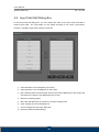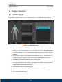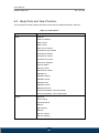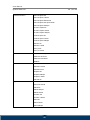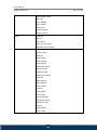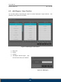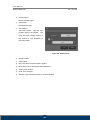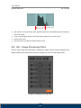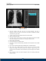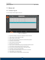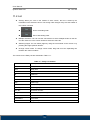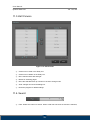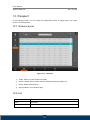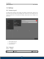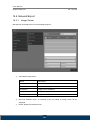
1
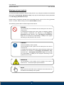
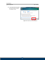
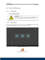
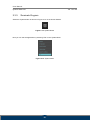
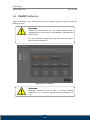
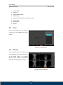
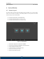
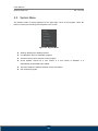
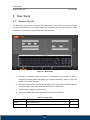
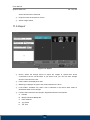
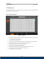
User Manual Human Acquisition and diagnostic software Doc No.: TM -721-EN Rev 1.0.1. Aug 2013 Part No.: CR-FPM-04-021-EN 3DISC, FireCR, Quantor and the 3D Cube are trademarks of 3D Imaging & Simulations Corp, South Korea, and its affiliates. All other trademarks are held by their respective owners and are used in an editorial fashion with no intention of infringement. The data in this publication are for illustration purposes only and do not necessarily represent standards or specifications, which must be met by 3D Imaging & Simulations Corp. All information contained herein is intended for guidance purposes only, and characteristics of the products and services described in this publication can be changed at any time without notice. Products and services may not be available in your local area. Please contact your local sales representative for availability information. 3D Imaging & Simulations Corp. strives to provide as accurate information as possible, but shall not be responsible for any typographical error. © Copyright 2010 3D Imaging & Simulations Corp, all rights reserved, printed, and published in South Korea by 3D Imaging & Simulations Corp. User Manual QuantorMed Plus TM -721-EN Contact 815, Tamnip-Dong, Yuseong-Gu, Daejeon, Korea Tel : 82-42-931-2100 Fax : 82-42-931-2299 Website : www.3DISCimaging.com E-mail : [email protected] 3DISC Americas 22560 Glenn Dr, Suite 116 Sterling, VA 20164 USA Tel : 1-703-430-6080 E-mail : [email protected] 3DISC Europe Gydevang, 39-41, 3450 Alleroed, Denmark Tel : 45-88-276-650 E-mail : [email protected] 2 User Manual QuantorMed Plus TM -721-EN Warnings and used symbols To ensure the safety of patients, staff and other persons, any changes to software and hardware delivered by 3D Imaging & Simulations Corp. may only be made with prior written permission from 3D Imaging & Simulations Corp. Please read the respective manuals of the connected devices, such as of the X-ray generator, sensor, or reader, before starting to use the QuantorMed+ software. The following symbols will be used throughout this manual: DANGER The functionality of the software can be destroyed in the case of incorrect use. If unauthorized changes have been made to delivered software and hardware components, the warranty by 3D Imaging & Simulations Corp. becomes void. 3D Imaging & Simulations Corp. will not accept any responsibility or liability for the proper functioning oh the product in such a case. DANGER General mandatory action manual. The functionality of the system can be destroyed in the case of incorrect use. If unauthorized changes have been made to delivered system and accessories, the warranty by 3D Imaging & Simulations Corp. becomes void. 3D Imaging & Simulations Corp. will not accept any responsibility or liability for the improper functioning of the product in such a case. WARNING The functionality of the system can be limited in the case of incorrect use. Hints that require special attention. NOTE Notes represent information that is important to know but which do not affect the functionality of the system. 3 User Manual QuantorMed Plus TM -721-EN Medical Device Security Users must take steps to secure their networks and protect their Medical Information Systems which includes a risk assessment strategy, network defense in depth strategy, business continuity planning, etc. User Authentication Only authorized users should log on to computers on which medical information systems are installed. Password Security In today’s world, passwords can be compromised in literally seconds by using a wide variety of tools and techniques. To lower the possibility of a compromised password, it is vital to adhere to a set of protocols. Choose a password between 7 ~ 10 characters using both alpha and numeric characters. Do not share the password. Do not base the password on a pet’s name, a relative’s name or any dictionary word. Do not write down the password. Do not leave the account logged on. User Access Control Configure the workstation to prompt for logon after coming out of stand-by mode. Internet Usage Accessing to the Internet exposes the computer to a plethora of vulnerabilities such as: Viruses Spyware Trojans Hostile Codes It is not recommended to install any unauthorized software on the computer. Peer-topeer software can expose your entire hard drive to any individual running the same type of software. Antivirus Products Use of antivirus software can increase CPU and memory usage, which can cause a slight degradation in the performance of the system. However, functionality should not be affected. Physical Security It is recommended that the user employs some method of physical security when dealing with the system to ensure that only authorized personnel have access to the product. 4 User Manual QuantorMed Plus TM -721-EN There are several vulnerabilities a malicious user could exploit locally. Some examples are: Theft of equipment Local password cracking Installation of hardware key loggers 5 User Manual QuantorMed Plus TM -721-EN Table of contents 1. Introduction .............................................................................. 10 1.1. Main Features..................................................................................11 2. Installation ................................................................................ 12 2.1. Environment ................................................................................... 12 2.1.1. Recommended Computer Requirement ........................................................ 12 2.1.2. Minimum Computer Requirement .................................................................. 12 2.2. Installation ...................................................................................... 13 2.2.1. 2.3. Software Installation ....................................................................................... 13 Start and Termination ..................................................................... 17 2.3.1. System Start ................................................................................................... 17 2.3.2. Start Program ................................................................................................. 17 2.3.3. Terminate Program ......................................................................................... 18 2.4. FireCR Calibration.......................................................................... 19 2.4.1. Calibration Geometry ..................................................................................... 21 2.4.2. Step 1: Auto Alignment ................................................................................... 22 2.4.3. Step 2: Erase .................................................................................................. 22 2.4.4. Step 3: Scan Blank ......................................................................................... 23 2.4.5. Step 4: Scan Low Dose .................................................................................. 24 2.4.6. Step 5: Scan Mid Dose ................................................................................... 25 2.4.7. Step 6: Scan High Dose ................................................................................. 26 2.4.8. Step 7: Calibration! ......................................................................................... 27 2.4.9. Step 8: Cancel ................................................................................................ 27 2.4.10. Note ................................................................................................................ 28 3. Screens .................................................................................... 30 3.1. 3.2. Supported Resolutions ................................................................... 30 Home .............................................................................................. 30 3.3. 3.4. 3.5. 3.6. 3.7. 3.8. 3.9. Navigation Bar ................................................................................ 31 Studies ........................................................................................... 31 New Study ...................................................................................... 32 Region Selection ............................................................................ 32 Patient Information ......................................................................... 32 Scan ............................................................................................... 33 Review............................................................................................ 33 4. Home Window .......................................................................... 34 6 User Manual QuantorMed Plus 4.1. 4.2. TM -721-EN Screen Layout ................................................................................ 34 System Menu.................................................................................. 35 5. New Study ................................................................................ 36 5.1. 5.2. Screen Layout ................................................................................ 36 Input Field Edit Dialog Box ............................................................. 38 6. Region Selection ...................................................................... 39 6.1. 6.2. 6.3. Screen Layout ................................................................................ 39 Body Parts and View Positions ....................................................... 40 Add Region, View Position ............................................................. 43 7. Scan ......................................................................................... 46 7.1. 7.2. 7.3. Screen Layout ................................................................................ 46 Exposure Input ............................................................................... 47 Cassette Indicator........................................................................... 47 8. Image ....................................................................................... 48 8.1. 8.2. 8.3. 8.4. 8.5. Screen Layout ................................................................................ 48 ROI ................................................................................................. 49 Marking ........................................................................................... 49 Rotate/Flip ...................................................................................... 50 Auto Window .................................................................................. 51 8.6. 8.7. 8.8. 8.9. 8.10. 8.11. Retake ............................................................................................ 51 Reject ............................................................................................. 51 QA – LUT Curve ............................................................................. 52 QA – Image Processing Filters ....................................................... 53 Send Image .................................................................................... 54 Exposure Index............................................................................... 55 9. Task List ................................................................................... 55 9.1. 9.2. 9.3. Screen Layout ................................................................................ 55 Stitch .............................................................................................. 57 Print ................................................................................................ 58 10. Review ..................................................................................... 61 10.1. 10.2. 10.3. 10.4. 10.5. 10.6. Screen Layout ................................................................................ 61 View Caption Bar ............................................................................ 63 Full Screen ..................................................................................... 63 Image Manipulation ........................................................................ 64 Measurement.................................................................................. 65 Marking ........................................................................................... 68 7 User Manual QuantorMed Plus 10.7. 10.8. 10.9. TM -721-EN File.................................................................................................. 68 Tools ............................................................................................... 68 Apply Range ................................................................................... 69 11. Study List ................................................................................. 70 11.1. 11.2. 11.3. 11.4. 11.5. Screen Layout ................................................................................ 70 List .................................................................................................. 71 Edit Column .................................................................................... 72 Search ............................................................................................ 72 Export ............................................................................................. 73 12. Work List .................................................................................. 75 12.1. 12.2. Screen Layout ................................................................................ 75 List .................................................................................................. 76 13. Transport .................................................................................. 77 13.1. 13.2. Screen Layout ................................................................................ 77 List .................................................................................................. 77 14. Settings .................................................................................... 79 14.1. Screen Layout ................................................................................ 79 14.2. General........................................................................................... 79 14.2.1. Option ............................................................................................. 79 14.2.2. User Information ............................................................................. 80 14.2.3. Password for Processing Parameter .............................................. 80 14.2.4. Display Language ........................................................................... 80 14.3. Fonts .............................................................................................. 80 14.3.1. Common ......................................................................................... 80 14.3.2. Marking ........................................................................................... 81 14.3.3. Printer ............................................................................................. 81 14.4. Network/Export ............................................................................... 82 14.4.1. Image Server .................................................................................. 82 14.4.2. Work List Server ............................................................................. 83 14.4.3. DICOM Printer ................................................................................ 83 14.4.4. Options ........................................................................................... 84 14.5. Work List ........................................................................................ 85 14.5.1. Work List ........................................................................................ 85 14.6. Overlay ........................................................................................... 85 14.6.1. Marking ........................................................................................... 85 14.6.2. Auto Mark Margin ........................................................................... 85 8 User Manual QuantorMed Plus TM -721-EN 14.6.3. Print Overlay Contents ................................................................... 86 14.7. System ........................................................................................... 86 14.7.1. Exposure Input ............................................................................... 86 14.7.2. File Management ............................................................................ 86 14.7.3. System Options .............................................................................. 87 14.7.4. Date ................................................................................................ 87 9 User Manual QuantorMed Plus TM -721-EN 1. Introduction QuantorMed+ is intuitive, easy-to-use workstation software that provides facilities using 3D Imaging & Simulations Corp. CR readers with optimized image acquisition, processing, and management capabilities. Its DICOM compliant interface allows for simple integration into a facility’s HIS, RIS, and PACS, providing the full range of capabilities needed for improved productivity and workflow in busy clinics and practices. This user manual provides detailed information about the operation of QuantorMed+ and the use of the range of facilities included in the software to make the processing and administration of your medical X-ray images as efficient as possible. Safety Instruction To ensure the safety of patients, staff and other persons, any changes to software and hardware delivered by 3D Imaging & Simulations Corp. may only be made with prior written permission from 3D Imaging & Simulations Corp. Liability If unauthorized changes have been made to delivered software and hardware components, the warranty by 3D Imaging & Simulations Corp. becomes void. 3D Imaging & Simulations Corp. will not accept any responsibility or liability for the improper functioning of the product in such a case. QuantorMed+ is not approved for the acquisition of mammographic image data. 10 User Manual QuantorMed Plus TM -721-EN 1.1. Main Features Image Acquisition & Study Management QuantorMed+ Software allows facilities to quickly input patient data – or access it directly from their HIS, RIS or PACS for improved productivity and accuracy. Image acquisition is supported by a fully developed list of exams and anatomies, and a viewer displays images on a monitor to facilitate quality control and image management. Once completed, the study can be sent to the PACS, printed on a dry film printer, or burned onto a CD or DVD. Image Manipulation, Multi-Viewing & Stitching To optimize images, technicians can crop, etch, enhance, increase brightness and contrast, and perform other adjustments. Regions of interest can be highlighted, and users can easily change the order of images or delete images in the multi-view window. Stitching capabilities for images of legs, spines, and other anatomical areas are particularly useful for orthopedic and chiropractic facilities. Integrated Viewer For smaller facilities without a HIS, RIS or PACS, QuantorMed+’s local database enables direct management of patients and studies utilizing a unique viewer function. Technicians and radiologists can review DICOM and non-DICOM images on the same station they acquired it on. Full Range of Output Options QuantorMed+ features a full range of output options, including DICOM CD-burn, embedded view, DICOM send SCU, and DICOM print for dry film printers. The combined DICOM Patient CD and dry film print creates patient CD / DVDs that include DICOM DIR structure and a built-in viewer. 11 User Manual QuantorMed Plus TM -721-EN 2. Installation 2.1. Environment 2.1.1. Recommended Computer Requirement Operating System CPU Memory Microsoft Windows 7, 8 Intel CORE i5 RAM 4 GB or more Hard Disk 500 GB Free Hard Disk Space Network Video Video Resolution 1 Gbps Ethernet 32-bit Color Display 1920 x 1080, 1440 x 900 2.1.2. Minimum Computer Requirement Operating System CPU Memory Microsoft Windows XP Intel Processor RAM 2 GB or more Hard Disk 80 GB Free Hard Disk Space Network Video Video Resolution 1 Gbps Ethernet 32-bit Color Display 1366 x 768, 1280 x 800, 1600 x 900, 1280 x 1024 12 User Manual QuantorMed Plus TM -721-EN 2.2. Installation 2.2.1. Software Installation Log on to the PC using an administrator account. Connect USB Dongle to USB port. Insert Installation CD. Install program will automatically launch. If the install program is not launched automatically, find and execute the “QuantorMed 2.x.x. Setup.exe” file on the CD. Click the “Next” button as shown in Figure 2.1. Figure 2.1. Welcome Dialog Box Choose all components and click the "Next" button as shown in Figure 2.2. Figure 2.2. Components Dialog Box 13 User Manual QuantorMed Plus TM -721-EN Choose your language and click the "Next" button as shown in Figure 2.3. Figure 2.3. Components Dialog Box Choose the destination folder and click the "Install" button as shown in Figure 2.4. Figure 2.4. Installation Location Dialog Box Installation status will be displayed as shown in Figure 2.5. Figure 2.5. Install Status Dialog Box 14 User Manual QuantorMed Plus TM -721-EN Installation status of the Dongle Driver will be displayed as Shown in Figure 2.6 Figure 2.6. Installation of dongle Driver Installation status of the FireCR USB driver will be displayed as Shown in Figure 2.7 Figure 2.7. Installation of FireCR USB Driver If installation is successful, Figure 2.8 will show up. Click "Finish" to finish the installation. Figure 2.8. Installation Finish Dialog Box 15 User Manual QuantorMed Plus TM -721-EN If the Windows Security Dialog Box pops up after installation, click [Allow access]. Figure 2.9. Windows Security Dialog Box 16 User Manual QuantorMed Plus TM -721-EN 2.3. Start and Termination 2.3.1. System Start 1. Turn on the FireCR CR Reader. 2. Turn on the monitor and PC. WARNING Do not run any application software other than QuantorMed during operation of the scanner. This may slow the scanner response. 2.3.2. Start Program After Windows is successfully booted, you can launch the QuantorMed+ program by double clicking the QuantorMed+ icon on your desktop as shown in figure 2.11. Figure 2.10. Home Window QuantorMed+ Figure 2.11. Short Cut Icon 17 User Manual QuantorMed Plus 2.3.3. TM -721-EN Terminate Program Select the System button as shown in Figure 2.12 on the Home Window. Figure 2.12. System Button Now you can exit the application by selecting "Exit" in the System Menu. Figure 2.13. System Menu 18 User Manual QuantorMed Plus TM -721-EN 2.4. FireCR Calibration Select IP Calibration in the System Menu, then the following window will pop up. Follow the steps in the menu. WARNING Calibrate the scanner before use. The “Please calibrate system” message pops up if the scanner is not calibrated or calibration data does not exist. It is recommended to calibrate the reader after moving it and as a part of regular maintenance. Figure 2.14. IP Calibration WARNING Calibration should be done for both a Universal Cassette containing IP 14” x 17” and a Universal Cassette containing IP 10” x 12”. 19 User Manual QuantorMed Plus TM -721-EN Name Auto Alignment Erase Scan Blank Description Alignment of laser beam position. Erase IP. Create the first calibration image file. Scan Low Dose Create the second calibration image file. Scan Mid Dose Create the third calibration image file. Scan High Dose Create the fourth calibration image file. Calibration Cancel Cassette Size Create a calibration data file. After a successful calibration the calibration window will automatically close. Close the IP Calibration window. This will abort the current calibration. Select the IP size for calibration. Accept a calibration image file. The Accept Accept button is displayed to accept calibration image files with values out of range. Reject a calibration image file. The Reject Reject button is displayed to reject calibration image files with values out of range. 20 User Manual QuantorMed Plus 2.4.1. TM -721-EN Calibration Geometry Figure 2.15. Calibration Geometry WARNING X-ray radiation field must cover the whole area of the cassette. 21 User Manual QuantorMed Plus 2.4.2. TM -721-EN Step 1: Auto Alignment Figure 2.16. Auto Alignment 2.4.3. Perform Auto Alignment before starting calibration to find the optimal laser beam position. Step 2: Erase Figure 2.17. Erase The Erase button is enabled when the cassette is inserted to the reader. It erases the cassette before calibration. 22 User Manual QuantorMed Plus 2.4.4. TM -721-EN Step 3: Scan Blank Figure 2.18. Scan Blank The Scan Blank button is enabled after performing the Erase step. After the Erase step, insert the cassette with no X-ray exposure into the reader and click Scan Blank to acquire the first calibration image. The mean intensity value of the blank image is displayed beneath the button. The mean intensity value of the blank image is displayed in green if the value is within the acceptable range. The mean intensity value of the blank image is displayed in red if the value is not within the acceptable range. If the mean intensity value of the blank image is displayed in red, click Accept to continue anyways or Reject to try again. To lower the mean intensity value of the blank image, click Erase again. 23 User Manual QuantorMed Plus 2.4.5. TM -721-EN Step 4: Scan Low Dose Figure 2.19. Scan Low Dose The Scan Low Dose button is enabled after performing a Scan Blank. Expose the cassette to the X-ray with the conditions noted below the Scan Low Dose button. Then, insert the cassette into the reader and click Scan Low Dose to acquire the second calibration image. The mean intensity value of the low dose image is displayed beneath the button. The mean intensity value of the low dose is displayed in green if the value is within the acceptable range. The mean intensity value of the low dose is displayed in red if the value is not within the acceptable range, click Accept to continue anyways or Reject to try again. Increase the X-ray dose to increase the mean intensity value or lower the X-ray dose to decrease the mean intensity value. *If changes are made to technique (Dose) please note the new values used (KVp, mAs) and input the new data in C:\QuantorMed+\firecr.ini 24 User Manual QuantorMed Plus 2.4.6. TM -721-EN Step 5: Scan Mid Dose Figure 2.20. Scan Mid Dose The Scan Mid Dose button is enabled after performing a Scan Low Dose. Expose the cassette to the X-ray with the conditions noted below the Scan Mid Dose button. Then, insert the cassette into the reader and click Scan Mid Dose button to acquire the third calibration image. The mean intensity value of the mid dose image is displayed beneath the button. The mean intensity value of the mid dose is displayed in green if the value is within acceptable range. The mean intensity value of the mid dose is displayed in red if the value is not within the acceptable range, click Accept to continue anyways or Reject to acquire the mid dose image again. Increase the X-ray dose to increase the mean intensity value or lower the X-ray dose to decrease the mean intensity value. 25 User Manual QuantorMed Plus 2.4.7. TM -721-EN Step 6: Scan High Dose Figure 2.21. Scan High Dose The Scan High Dose button is enabled after performing a Scan Mid Dose. Expose the cassette to the X-ray with the conditions noted below the Scan High Dose button. Then, insert the cassette into the reader and click Scan High Dose button to acquire the fourth calibration image. The intensity value of the high dose image is displayed beneath the button. The intensity value of the high dose is displayed in green if the value is within the acceptable range. The intensity value of the high dose is displayed in red if the value is not within the acceptable range, click Accept to continue anyways or Reject to acquire the high dose image again. Increase the X-ray dose to increase the mean intensity value or lower the X-ray dose to decrease the mean intensity value. *If changes are made to technique (Dose) please note the new values used (KVp, mAs) and input the new data in C:\QuantorMed+\firecr.ini 26 User Manual QuantorMed Plus 2.4.8. TM -721-EN Step 7: Calibration! Figure 2.22. Calibration 2.4.9. The Calibration button is enabled after performing a successful Scan High Dose. Click the Calibration button to generate calibration data. Calibration data is saved in your local program folder. After generation of calibration data, the calibration window closes automatically. Step 8: Cancel You can exit calibration window in the middle of process. This will abort your current calibration process. 27 User Manual QuantorMed Plus TM -721-EN 2.4.10. Note When the mean intensity value for each step is within acceptable range, values are shown in green. Figure 2.23. Proper Calibration When the mean intensity value for each step is not within acceptable range, values are shown in red. Figure 2.24. Improper Calibration Start the calibration process from Auto Alignment or Erase for recalibration of the reader. 28 User Manual QuantorMed Plus TM -721-EN NOTE Following the calibration process, two sets of four images used for calibration and two calibration files are generated in local program folder. 29 User Manual QuantorMed Plus TM -721-EN 3. Screens 3.1. Supported Resolutions Landscape resolutions with 16:9, 4:3 and 5:4 ratios are supported. Portrait ratios are not supported. The horizontal resolution of the monitor must be at least 1280 pixels, and the vertical resolution of the monitor must be at least 768 pixels. Recommended resolutions are listed in Table 3.1. Table 3.1 Screen Ratio Screen Resolution 1366 x 768 1280 x 800 16:9 1400 x 900 1600 x 900 1920 x 1080 4:3, 5:4 1280 x 1024 3.2. Home The Home screen is the first screen that appears when the program is run. From the Home screen, you can create a new study or view existing studies. Figure 3.1. Home Screen 30 User Manual QuantorMed Plus TM -721-EN 3.3. Navigation Bar The Navigation Bar is located at the bottom of the screen. The Navigation Bar is always displayed while the program is running, allowing the user to easily switch screens during a task. ② ① ⑤ ④ ③ Figure 3.2. Navigation Bar ① Home ② Studies ③ Region Selection ④ Scan ⑤ Review 3.4. Studies The Studies screen shows a collection of ① windows that are related to the studies. You can enter the Studies screen by clicking the Studies button in the ② ③ Navigation Bar. The Sub-Navigation Bar is located on the left of the screen. In the Sub-Navigation Bar, you can select a Study List, Work List or Transport windows that are related to the study. Figure 3.3. Studies Screen ① Study List: You can perform various tasks by searching existing studies and selecting a study. ② Work List: You can query the work list from the PACS work list server, select the desired study and immediately begin image acquisition. ③ Transport: You can confirm the transmission results of the acquired images. 31 User Manual QuantorMed Plus TM -721-EN 3.5. New Study The New Study screen is the first page for performing a scan. After entering the necessary patient information and study information, and adding a new study, you can begin a scan. Figure 3.4. New Study 3.6. Region Selection In the Region Selection screen, you can select the region to scan and add it to the Task List. Figure 3.5. Region Selection 3.7. Patient Information The Patient Information Bar is displayed at the top of all the screens, with the exception of the Home screen and the New Study screen. The Patient Information Bar displays patient information and other related information. ① ② ③ ④ ⑥ ⑤ Figure 3.6. Patient Information 32 ⑦ ⑧ User Manual QuantorMed Plus TM -721-EN ① Patient Name ② Patient ID ③ Patient's Date of Birth ④ Patient's Age ⑤ Patient's Sex (M: Male, F: Female, O: Other) ⑥ Current Time ⑦ Model Name ⑧ System 3.8. Scan In the Scan screen, you can insert a cassette into the FireCR and acquire images. Figure 3.7. Scan Screen 3.9. Review In the Review screen, you can query scanned images in the identical manner as the PACS Viewer. The Review screen is very useful for conducting diagnosis after acquiring the images. Figure 3.8. Review Screen 33 User Manual QuantorMed Plus TM -721-EN 4. Home Window 4.1. Screen Layout The Home screen is the first screen that appears when the program is run. From the Home screen, you can create a new study or view existing studies. You can go back to the Home screen by using one of the actions below. Clicking the Home button in the Navigation Bar Clicking the End Study button in the Scan screen Clicking the End Study button in the Review screen ① ② ④ ⑤ ⑥ Figure 4.1. Home Window ① Model Name: Displays the model name of FireCR. ② Current Time: Current time is displayed in hours and minutes. ③ System: Displays the System menu. ④ Create New Study: Go to New Study screen. ⑤ Study List: Go to Study List screen. ⑥ Work List: Go to Work List screen. 34 ③ User Manual QuantorMed Plus TM -721-EN 4.2. System Menu The System button is always displayed in the upper-right corner of the program. When the button is clicked, the following menu appears on the screen. Figure 4.2. System Menu Settings: Displays the Settings window. IP Calibration: Runs IP Calibration program. Scanner Control: Runs Scanner Control program. Check Update: Checks for a new version. If a new version is available, it is automatically downloaded and installed. About this software: Displays software version information Exit: Exits the program. 35 User Manual QuantorMed Plus TM -721-EN 5. New Study 5.1. Screen Layout The New Study screen is the first page when performing a scan. Enter the necessary patient and study information. You can easily switch to the next input field by using the Tab key. Fields marked by * are mandatory DICOM fields that must be filled in. ③ ② ① ④ ⑤ ⑥ Figure 5.1. New Study ① Emergency: Mandatory fields are filled in automatically. This function is used in emergencies where patient information has not been identified to perform a scan first and fill in the patient data later. ② Edit Input Field: Bring up Input Field Edit dialog. In the Input Field Edit dialog, you can change the order of the input fields, and add or remove input fields. ③ System Menu: Display the System menu. ④ Input Field: Details about each input field are described in Table 5-1. Table 5.1. Input Field Title Description Mandatory Name Enter patient name. O ID Enter patient ID. O 36 User Manual QuantorMed Plus TM -721-EN Enter patient’s date of birth. You can select a date from the drop-down box or manually enter numbers. When only the Birth date of birth is entered and not the age, age is calculated O automatically. Select patient’s sex. M stands for male. F stands for Female. Sex N/A stands for other. O Enter patient’s age. Leave the Year field blank if the patient is less than 1 year old. When only the age is entered and not the Age date of birth, date of birth is calculated automatically. When it X does, month and date are automatically entered as January 1. Ref. Physician Enter the name of the referring physician. X Description Enter study description. X Enter accession number. Entering an accession number is Accession No. mandatory. If not entered, a new number will be generated automatically. ⑤ Page Up/Down: Go to another page. ⑥ Next: Go to the Region Selection screen, which is the next step. 37 O User Manual QuantorMed Plus TM -721-EN 5.2. Input Field Edit Dialog Box In the Input Field Edit dialog box, you can change the order of the input fields, and add or remove input fields. The input fields can be edited according to the user’s environment. However, mandatory input fields cannot be removed. ① ② ③ ⑤ ④ ⑥ ⑦ ⑧ Figure 5.2. Input Field Edit ① Input field items to be displayed on the screen. ② Input field items not to be displayed on the screen. ③ Move selected items to left and right. Items on the left are displayed on the screen and the items on the right are not displayed on the screen. ④ Button for switching pages. ⑤ Move the selected items up or down on the list to change order. ⑥ Save changes and close the dialog box. ⑦ Cancel changes and close the dialog box. ⑧ Reset the fields to default settings. 38 User Manual QuantorMed Plus TM -721-EN 6. Region Selection 6.1. Screen Layout In the Region Selection screen, you can select the region to scan and add it to the Task List. ① ② ③ ⑥ ④ ⑤ ⑦ ⑧ Figure 6.1. Region Selection ① Body Part: The region to be scanned will be displayed on the figure of the human body. When you move the mouse cursor over the figure, the region to be selected will be marked by a different color. Select the desired region and the View Position List will be updated. ② View Position: Displays view positions that correspond with the selected region for scanning. Click on the region to scan and the region will be added to the Task List. ③ ④ Add Region, View Position: Add new region or view position. Preset: Displays view position presets. When a certain setting is used frequently, you can easily automatically add multiple view positions by selecting a preset instead of adding separate view positions each time. ⑤ Page Up/Down: Button for switching pages. ⑥ Task List: List of view positions added from View Position or Preset fields. ⑦ Previous: Go back to New Study screen. ⑧ Next: Proceed to Scan screen. 39 ⑧ User Manual QuantorMed Plus TM -721-EN 6.2. Body Parts and View Positions The body parts and view positions provided in the product by default are listed in Table 6.1. Table 6.1. View Position Body Part View Position Head Skull AD Skull PA Caldwell Skull Townes Skull Lateral Sella Turcica Lateral Facial Bones PA Caldwell Facial Bones Waters Facial Bones Lateral Facial Bones Townes Sinuses PA Caldwell Sinuses Waters Sinuses Lateral Nasal Bones Lateral Mandible AP Mandible Oblique Mandible Lateral Mastoids Laws Mastoids Townes Mastoids Stenvers Temporomandibular Joint Open Mouth Temporomandibular Joint Closed Mouth Thorax Chest PA Chest Lateral Chest Decubitus Ribs AP Ribs Oblique Ribs PA Sternum Lateral Sternum Oblique 40 User Manual QuantorMed Plus Vertebral Column TM -721-EN Cervical Spine AP Cervical Spine Lateral Cervical Spine Swimmers Cervical Spine AP Open Mouth Cervical Spine Oblique Thoracic Spine AP Thoracic Spine Lateral Thoracic Spine Oblique Lumbar Spine AP Lumbar Spine Lateral Lumbar Spine Oblique Sacrum AP Sacrum Lateral Coccyx AP Coccyx Lateral Abdomen Abdomen AP Supine Abdomen AP Erect Abdomen Decubitus KUB AP Shoulder Shoulder AP Shoulder Lateral Shoulder Axial Scapula AP Scapula Oblique Scapula Lateral Clavicle AP Upper Extremities Humerus AP Humerus Lateral Elbow AP Elbow Oblique Elbow Lateral Forearm AP Forearm Lateral Wrist AP Wrist Lateral Wrist Oblique 41 User Manual QuantorMed Plus TM -721-EN Wrist Carpal Tunnel Hand PA Hand Oblique Hand Lateral Fingers AP Fingers Oblique Fingers Lateral Pelvis Pelvis AP Hip AP Hip Lateral Hip Frog Leg Lateral Sacroiliac Joints Oblique Lower Extremities Femur AP Femur Lateral Knee AP Knee Lateral Knee Oblique Knee Skyline Patella Sun Raise Patella Lateral Tibia/Fibula AP Tibia/Fibula Lateral Ankle AP Ankle Mortise Ankle Oblique Ankle Lateral Foot AP Foot Oblique Foot Lateral Foot Sesamoids Calcaneus Lateral Calcaneus Axial Toes AP Toes Oblique Toes Lateral 42 User Manual QuantorMed Plus TM -721-EN 6.3. Add Region, View Position You can add, delete or edit body part, region or position displayed in region selection. Attributes of each preset can be edited. ① ② ④ ⑤ ③ ⑥ ⑦ ⑫ ⑧ ⑨ ⑬ ⑩ ⑪ ⑭ Figure 6.2. Add Region, View Position ① Body Part ② Region ③ Position ④ Add Region: Add new region. Type the new exam name in the window. Figure 6.3. Add Region 43 And User Manual QuantorMed Plus ⑤ TM -721-EN Delete Region: Delete selected region. ⑥ Edit Region: Edit selected region. ⑦ Add Position: Add new position. Type the new position name in the window. Tick Copy and type existing position in the window to copy properties to the new position. Figure 6.4. Add Position ⑧ Delete Position ⑨ Edit Position ⑩ Move Up: Move selected position upward. ⑪ Move Down: Move selected position downward. ⑫ Close: Close window. ⑬ Save: Save changes. ⑭ Attribute: Open Attribute window for selected position. 44 User Manual QuantorMed Plus TM -721-EN Figure 6.5. Attribute Window ① Name: Name of position ② ROI: Set default ROI. ③ Flip: Set default flip of the image. ④ Rotate: Set default rotation of the image. ⑤ Marking Position: Set default marking position on the image. ⑥ Marking: Set default marking on the image. 45 User Manual QuantorMed Plus TM -721-EN 7. Scan 7.1. Screen Layout In the Scan screen, you can insert a cassette into the FireCR and acquire images. ④ ⑥ ① ② ③ ⑤ ⑦ ⑧ Figure 7.1. Scan ① Scan: Begin a scan. ② Stop: Stop a scan. ③ Erase: Erase the IP. By default, the IP is deleted automatically after a scan. This function is only used to manually delete the IP. ④ Progress: The scanning progress is shown in a circle and in percentages. ⑤ Resolution: Select the scan resolution. HD resolution scans with 100 mm pixel pitch, and SD resolution scans at 200 mm pixel pitch. Lower pixel pitch results in higher resolution images. ⑥ Cassette Indicator: Displays the status of the cassette. ⑦ Exposure Input: Enter the X-ray exposure settings. ⑧ Model Name: Displays the model name of FireCR connected to the PC. 46 User Manual QuantorMed Plus TM -721-EN 7.2. Exposure Input Enter the X-ray exposure settings. Exposure Input field is only activated when it is enabled in [System – Exposure Input]. The entered values will be included in the DICOM information. As shown in Table 7.1, 4 types can be entered. Table 7.1. Exposure Input Type kVp mA ms mAs 1 O O O Calculated automatically 2 O X X O 3 O O Calculated O automatically 4 O Calculated O O automatically 7.3. Cassette Indicator The Cassette Indicator displays whether the cassette is inserted and recognized correctly. Table 7.2 . Cassette Indicator Indicator Status A cassette is not inserted. A cassette is inserted, but cassette size information is not recognized. A cassette is inserted, cassette size information is recognized, but the current size has not been calibrated. The status is okay and ready for scan. 47 User Manual QuantorMed Plus TM -721-EN 8. Image 8.1. Screen Layout When an IP scan has been completed, the acquired image is displayed on the Scan window as shown in Figure 8.1. ② ③ ① ④ ⑤ ⑥ ⑦ ⑧ ⑨ ⑩ ⑪ Figure 8.1. Image ① ROI Box: A tool for cropping the valid region of the scanned image. ② ROI: ROI-related tools ③ Marking: Add markings on the image. ④ Rotate Flip: Rotate/flip the image. ⑤ Auto Window: Automatically adjust the image brightness and contrast. ⑥ Retake: Scan the image again. ⑦ Reject: Reject the image. ⑧ QA: Bring up tools for adjusting image details. ⑨ Send Image: Transmit the image. ⑩ Image Comment: Write image comment ⑪ Exposure Index: Show the exposure index value of the scanned image. 48 User Manual QuantorMed Plus TM -721-EN 8.2. ROI When a scan is completed, the image is displayed and the ROI Box of the predefined size for each scanned region is automatically displayed as shown in Figure 8-1. When you drag the ROI Box to the desired location and double-click the ROI Box or click on the ROI button, the ROI is cropped and fitted to the screen as shown in Figure 8.2. To adjust the size of the ROI Box, drag the small rectangles at each corner of the ROI. When transmitting or printing the image, only the ROI are used. Figure 8.2. ROI Cropped Image To bring up the ROI Box again, double-click on the image or click on the ROI button. When you click on the ROI button, the film sizes listed below will be displayed on the screen. When you select one of the given sizes, the ROI Box will be adjusted to that size. 8 x 10, 10 x 12, 14 x 14, 14 x 17, 10 x 8, 12 x 10, 17 x 14 8.3. Marking The Marking feature is used to add markings on the image. Markings can be added to the image by selecting a predefined marking or manually typing in text. 49 User Manual QuantorMed Plus TM -721-EN Add Predefined Markings ① Click on the Marking button. ② Select a marking. ③ Click on the image. ③ ② ① Predefined markings can be edited in Settings under [Overlay-Marking]. Figure 8.3. Add Predefined Markings Manually Enter Markings ① Click on the Marking button. ② Select Direct Input. ③ Click on the position where you want to ③ ① ② add the marking and a text input box will appear. Enter your text. Click outside the text input box when you are done. Figure 8.4. Manually Enter Markings 8.4. Rotate/Flip Used to rotate or flip images. Icon Action Rotate Left Rotate Right Flip Horizontally 50 User Manual QuantorMed Plus TM -721-EN Flip Vertically 8.5. Auto Window Automatically adjust the image brightness and contrast. 8.6. Retake Used when the quality of the scanned image is insufficient and requires a rescan. Remember that the current image will be deleted. 8.7. Reject When the quality of the scanned image is insufficient, Reject preserves the current image with a “Reject” marking without rescanning. When the Reject button is clicked, a “Reject’ marking is added on the upper left corner of the image as shown below, and a “Reason” input field appears on the screen. Type in the reason for rejection, and click outside the input box when you are done. You can cancel a rejection by clicking the Reject button again. Figure 8.5. Reject 51 User Manual QuantorMed Plus TM -721-EN 8.8. QA – LUT Curve Used to adjust the LUT Curve of the image. Adjusting the image requires expert knowledge about images. Adjusting the image without proper knowledge may result in lower image quality. ① ④ ⑤ ⑥ ② ③ ⑦ Figure 8.6. LUT Curve ① LUT Curve: LUT curve applied to the image. A default curve for each region is provided. The user can adjust the curve to their preference. To adjust the curve, set a control point and drag the curve using the mouse. To add a new control point, click on the line using the mouse. A control point can be removed by dragging it outside the box. ② Histogram: Shows the histogram of the image. The bright region at the center is the region currently displayed on the screen. The left part of the histogram indicates the frequency where X-ray penetration level is low and image is bright. The right part of the histogram indicates the frequency where X-ray penetration level is high and image is dark. Images have low pixel values in bright regions and high pixel values in dark regions. ③ Window Center / Width: Used to adjust the window center and width of the image. The window center is adjusted when you drag the image up or down, and window width is adjusted when you drag the image left or right. Dragging the sliders have the same effect as dragging the image. 52 User Manual QuantorMed Plus TM -721-EN Window Width Window Center ④ Set: Set the curve and window value adjusted by the user as the default value for images of the current region. ⑤ Load: Load and apply default curves and window values of the current region. ⑥ Reset: Reset curve. ⑦ Processing: Go to Image Processing Filters screen. 8.9. QA – Image Processing Filters Used to adjust image processing filters. Adjusting the image requires expert knowledge about images. Adjusting the image without proper knowledge may result in lower image quality. Figure 8.7. Image Processing Filter 53 User Manual QuantorMed Plus ① TM -721-EN Contrast: Increases the image’s contrast. The level can be adjusted from 0 to 10. Higher levels increase the intensity. Filter is not applied when 0 is selected. ② Detail Contrast: Increases the contrast in regions of the image with low contrast. The level can be adjusted from 0 to 10. Higher levels increase the intensity. Filter is not applied when 0 is selected. ③ Edge Enhancement: Enhances edges. It is used to increase visibility of blood vessels or small calcifications. The level can be adjusted from 0 to 5. Higher levels increase the intensity. Filter is not applied when 0 is selected. ④ Edge Frequency: Designates the range of the edges to emphasize. The level can be adjusted from 0 to 5. Lower level emphasizes the smaller edges. Higher levels emphasize the bigger edges. ⑤ Latitude Reduction: Compresses the low frequency regions to improve the overall visibility of the image. The level can be adjusted from 0 to 10. Higher levels increase the intensity. Filter is not applied when 0 is selected. ⑥ Noise Reduction: Reduces the noise in the image. The level can be adjusted from 0 to 10. Higher levels increase the intensity. Filter is not applied when 0 is selected. ⑦ Set: Set the filter values adjusted by the user as the default value for images of the current region. ⑧ Load: Load and apply filter values of the current region. ⑨ Reset: Reset filters. ⑩ LUT: Go to LUT Curve adjustment screen. 8.10.Send Image Immediately transmits current image to the image server designated in Settings. If [Network/Export – Options – Show Destination] is checked under Settings, a dialog box for choosing the destination will be displayed as shown in Figure 8.8 and the user can designate a destination. 54 User Manual QuantorMed Plus TM -721-EN Figure 8.8. Destination Select 8.11.Exposure Index Exposure Index is an approximate indicator of the dose that reaches the image receptor. 3DISC’s Exposure Index is calculated by following equation. Under the same exposure conditions, the indicator and the dose are proportional. The recommended EI value is between 1800 and 2200. 1800 < Dose < 2200: Dose is optimal Dose < 1800: Dose is too low Dose > 2200: Dose is too high 9. Task List 9.1. Screen Layout The Task List is a list of scans to be performed. Tasks are group by studies, and arranged in chronological order. The user can select the desired region and perform a scan. The Task List consists of a list of studies, and each study consists of a list of tasks. The check boxes located to the right of the task bar is used to select tasks. 55 User Manual QuantorMed Plus TM -721-EN ④ ⑥ ⑤ ③ ① ⑦ ② ⑧ ⑨ ⑩ ⑪ ⑫ Figure 9.1. Task List ① Study Bar: Displays study date, study time, and study description. Only time is displayed for studies conducted on the same day. Only dates are displayed for studies conducted on any prior dates. ② Task Bar: Displays thumbnail images, body part, and view position. ③ Select all: Select all the tasks. ④ Add Preset: Add the selected study to the preset. When added to the preset, the added study will be displayed on the Preset List in the Region Selection screen. ⑤ Delete: Delete selected tasks. ⑥ Edit: Show/hide Move and Switch buttons. ⑦ Send Study: Transmit the selected study. Destination of the transmission can be added in Settings. ⑧ Print: Print the selected images using a DICOM printer or a Windows printer. ⑨ Stitch: Used to stitch multiple images into one when long bones are scanned. To stitch images, all the images must have the identical scan resolution. Images scanned in SD resolution and in HD resolution cannot be stitched. Up to three images can be stitched into one. ⑩ Move: Change the order of the tasks. Change the order of the task by pressing the Up/Down buttons. 56 User Manual QuantorMed Plus ⑪ TM -721-EN Switch: Switch the images of two tasks. The button is only activated when two tasks are selected. ⑫ Page Up/Down: Button for switching pages. 9.2. Stitch The Stitch function is optional. A Stitch Dongle is required to use the Stitch function. When stitching begins, a screen shown in Figure 9.2 will be displayed on the screen and the selected images will be displayed vertically according to the order in the Task Bar. When you adjust the position and angle of the images and begin stitching, the two images will be stitched into one and added to the Task List. ① ② ③ ④ ⑤ ⑥ ⑦ ⑧ ⑨ ⑩ ⑪ ⑫ Figure 9.2. Stitch ① Zoom: Used to zoom in and out of the image. Drag the mouse over the image to control the zoom. It does not zoom in/out on a single image and zooms in/out on the entire screen. ② Pan: Pan the image. Drag the mouse over the image to control the zoom. The selected image pans separately. ③ Fit To Page Size: Adjust zoom to fit the image to the height of the screen. ④ Fit To Page Width: Adjust zoom to fit the width of the screen. 57 User Manual QuantorMed Plus ⑤ TM -721-EN Clip: Show/hide clip adjustment line in the image. Clip lines are displayed as dotted lines. Drag the dotted line using the mouse to clip the desired region. ⑥ Show Guide Line: Show/hide horizontal dotted line to check horizontal level of the scanned image. The position of the guide line can be adjusted by dragging it using the mouse. ⑦ Rotate Left: Rotate the selected image counter-clockwise. ⑧ Rotate Right: Rotate the selected image clockwise. ⑨ Rotate Angle: The angle to rotate the image. ⑩ Reset: Reset images. ⑪ Cancel: Return to the previous screen. ⑫ Stitch: Stitch images and return to the previous screen. 9.3. Print Windows printers and DICOM printers are supported. The printed page can be previewed on the left part of the screen. Figure 9.3. DICOM Print 58 User Manual QuantorMed Plus Printer Type: Select printer type. DICOM Printer Windows Printer Layout: Select the layout of the image to be printed on film or paper. 1x1 TM -721-EN 1x2 2x1 2x2 Film Size: Select standard DICOM film size. 8INx10IN 10INx12IN 10INx14IN 8INx10IN 11INx14IN 14INx14IN 14INx17IN 24CMx30CM 24CMx24CM Orientation: Select film orientation. Portrait: Uses portrait orientation. Landscape: Uses landscape orientation. Destination: Select DICOM printer. Print: Start printing. Stop: Stop printing. Cancel: Close dialog box. When a Window printer is selected, the screen changes as shown in Figure 9-4. 59 User Manual QuantorMed Plus TM -721-EN Figure 9.4. Window Printer 60 User Manual QuantorMed Plus TM -721-EN 10. Review 10.1.Screen Layout The View offers the identical functions as a PACS Viewer. It supports various image comparison, processing and measurement tools for performing a diagnosis. The screen displaying the image consists of multiple views. Each view consists of multiple images. The user can customize the view layout and image layout according to their needs. Image Image View Image Image View View Figure 10.1. View – Image Layout To display an image in the view, all you have to do is simply drag the image from the Task Bar. When an image is dragged from the Task Bar, only the image is displayed in the view. When a Study Bar is dragged, all the images included the study are displayed in the view. 61 User Manual QuantorMed Plus TM -721-EN ① ② ③ ④ ⑤ ⑥ ⑦ ⑧ ⑨ ⑩ ⑪ Figure 10.2. Review Screen ① View Caption Bar: The caption bar of the view. ② Full Screen: Show the review screen in full-screen mode. ③ View Window Layout: Change the layout of the view. ④ Zoom: Used to zoom in and out of the image. Drag the image left, right, up, or down ① using the mouse. ⑤ Pan: Pan the image. Drag the image left, right, up, or down using the mouse. ⑥ Image Manipulation: Open image manipulation tools for rotating, flipping and inverting images. ⑦ Measurement: Provides various measurement tools for measuring distance and angle. ⑧ Marking: Provides marking tools. ⑨ File: Display DICOM file on the screen. ⑩ Tools: Provides other tools. ⑪ Apply: Designate the range in which image adjustments will apply. 62 User Manual QuantorMed Plus TM -721-EN 10.2. View Caption Bar ① ① ② ③ ④ Figure 10.3. View Caption Bar ① Image Layout: Change image layout. When you click on the Image Layout button, a 3x3 grid shown in Figure 10.4 will appear on the screen. Select your desired layout. The largest image layout available 3x3. Figure 10.4. Image Layout ② Page Up: Go back to the previous page. ③ Page Down: Go to the next page. ④ Close: Close all images. 10.3.Full Screen Expands the Review screen to full-screen mode as shown in Figure 10.5. 63 User Manual QuantorMed Plus TM -721-EN Figure 10.5 Full Screen 10.4.Image Manipulation Icon Action Rotate Left Rotate Right Flip Horizontally Flip Vertically Reset image to initial state Negative image Fit to page size Real size 64 User Manual QuantorMed Plus TM -721-EN 10.5.Measurement Icon Action Distance Angle Rectangle Ellipse Polygon Free Draw Pixel View Cardiac Thorax Ratio Profile ① Distance: Measures distance. Click the start and end point of the measurement. A straight line is displayed between the two points and the measurement value is displayed at the end of the straight line. You can move the measuring line by dragging it. You can move either one of the two control points by dragging them with your mouse. You can also move the position of the measurement values by dragging it with your mouse. ② Angle: Measures angle. Click on the center point of the angle you wish to measure, and then click on two control points. You can move both lines at 65 User Manual QuantorMed Plus TM -721-EN once by dragging. You can also move either one of the two control points. You can also move the position of the measurement values by dragging them with your mouse. ③ Rectangle: Draws a rectangle. Click the mouse at the desired position of the upper left corner of the rectangle, and then drag the mouse to the desired position of the lower right corner of the rectangle and release the mouse button. Click on an area within the rectangle to move it. Drag the control points to resize the rectangle. ④ Ellipse: Draws an ellipse. Click the mouse at the desired position where the top and left-most point of the ellipse would intersect, drag the mouse toward the bottom right and release the mouse after reaching a desired size and shape. Click on an area within the ellipse to move it. Drag the control points to resize the ellipse. ⑤ Draws a polygon. A control point is added every time you click the mouse. Double-click when you are done drawing the polygon. Click on an area within the polygon to move it. Drag the control points to change the corners of the polygon. ⑥ Creates a free draw selection. Click and drag the mouse to the desired shape. Release the mouse when you are done drawing. You can click inside the selection to move the free draw selection. ⑦ Measures pixel value. Click and drag the mouse and the coordinates (x, y) and pixel values (p) of the pixel at the cursor position will be displayed on 66 User Manual QuantorMed Plus TM -721-EN the screen. ⑧ Measures cardiac thorax ratio. 1. Click on the left end point of the thorax. 2. Click on the right end point of the thorax. 3. Move the upper left control point to the left end point of the heart. 4. Move the upper right control point to the right end point of the heart. 5. The measurement value will be displayed in percent. ⑨ Profile: Draw a straight line in the same manner as measuring a distance, and a profile dialog box will be displayed automatically. 1. Distance: Distance between two points 2. Start Point: Start point information 3. End Point: End point information 4. Min: Minimum value 5. Max: Maximum value 67 User Manual QuantorMed Plus TM -721-EN 6. Mean: Average value 7. Current Value: Pixel value of the current position when the mouse was clicked over the graph ` 10.6.Marking Icon Action Arrow Text 10.7.File Icon Action Open DICOM File Open Image File Export as DICOM or image file. 10.8.Tools Icon Action Copy to clipboard: Copies the active image to the Windows clipboard. Sets pixel size. 1. Scan a measuring tool with a determined length. 2. Select the scanned image and click on the Pixel Calibration button. 3. The following dialog box will be displayed on the screen. Enter the actual length of the measuring tool. 68 User Manual QuantorMed Plus TM -721-EN 4. Click on the start point of the measuring tool over the image and start dragging. 5. Release the mouse at the end point of the measuring tool to complete the calibration. This function shows small box on the image if you click mouse left button. Auto window is applied to this small box area. You can change box size if you move mouse with “Shift” key down. 10.9.Apply Range Sets the range in which image processing will be applied. When comparing two images, you can apply the same filters to both windows for easier comparison. Icon Action Active: The image that was clicked last is the active image. The active image is marked by an orange border. Select: You can select multiple images by clicking on images while holding down the Ctrl key. The selected images are marked by a blue border. Study: Applies image filters to all images in the study that contain the active image. All: Applies image filters on all the images. Image filters that can be used with Apply Range are as follows. Zoom, Pan, Rotate, Flip, Window 69 User Manual QuantorMed Plus TM -721-EN 11. Study List 11.1.Screen Layout You can manage scanned images in Study List. ① ② ③ ④ ⑤ ⑥ ⑦ ⑧ ⑨ ⑩ ⑪ ⑫ ⑬ ⑭ Figure 11.1. Study List ① Edit Column: Display a dialog box for editing the columns of the list. ② Today: Search only the studies from today. ③ Search: Search various criteria ④ Filter: Search same patient’s study with the selected study’s patient. ⑤ Edit: Edit the selected studies. ⑥ Delete: Delete the selected studies. ⑦ New Study: Add a new study. ⑧ Region: Open the selected study and ⑭ go to the Region Selection screen. ⑨ Scan: Open the selected study and go to the Scan screen. ⑩ Review: Open the selected study and go to the Review screen. ⑪ Send Study: Transmit the selected studies. ⑫ Export: Export the selected studies to a CD, DVD or a local drive. ⑬ Page Up/Down: Go to another page. ⑭ Thumbnail: Displays thumbnail images of selected studies. ⑬ 70 User Manual QuantorMed Plus TM -721-EN 11.2.List Sorting: When you click on the header of each column, the list is sorted by the information in the selected column. The sorting order changes every time the header of the column is clicked. Sort in ascending order Sort in descending order Multiple selections: You can use the check boxes to select multiple studies on the list. Use the check box in the column header to select the entire list. Switching Pages: You can switch pages by using the scroll wheel on the mouse or by pressing the Page Up/Down buttons. Change column width: To change column width, drag and move the separating line between the column headers. The columns in the Study List are described in Table 11.1. Table 11.1. Study List Column Column Title Description Date Study date Time Study time Name Patient name ID Patient ID Sex Patient sex Birth Patient birth date Age Patient age Desc Study description Ref. Phy Referring physician’s name Acc. No. Accession number Image Number of acquired images Exam Number of tasks Print Status Print result Finish Status Image transportation result 71 User Manual QuantorMed Plus TM -721-EN 11.3.Edit Column ① ② ③ ⑤ ④ ⑥ ⑦ Figure 11.2. Edit Column ① Columns to be used in the Study List. ② Columns to be hidden in the Study List. ③ Move selected items left and right. ④ Button for switching pages. ⑤ Move the selected items up or down on the list to change order. ⑥ Save changes and close the dialog box. ⑦ Reset the program to default settings. 11.4.Search ① ① ② ③ Filter: Select the column to search. When a filter has not been set and All is selected, 72 User Manual QuantorMed Plus TM -721-EN all the columns will be searched. ② Keyword: Enter the keyword to search. ③ Search: Begin search. 11.5.Export ① ② ③ ④ ⑤ ⑨ ⑧ ⑥ ⑩ ⑦ ⑫ ⑪ ⑬ ⑭ ⑮ Figure 11.2. Export ① Device: Select the storage device to export the images to. Optical disc drives connected to the PC will be listed. If you select Local, you can use other storage devices connected to the PC. ② Label: Label to be displayed on disc. ③ Media Type: Displays the type of the media inserted in the drive. ④ Local Folder: Activated only when Local is selected in the Device field. Select a destination folder to save images. ⑤ Format: Select format to save images. Supported formats are as follows. A. DICOM B. Bitmap: Windows Bitmap file C. Raw: RAW file D. Jpg: JPEG E. Tiff: TIFF 73 User Manual QuantorMed Plus TM -721-EN ⑥ Log Message: Shows the progress when recording to an optical disc. ⑦ Progress Bar: Shows the image export progress. ⑧ Study List: Shows the list of selected studies. ⑨ Image List: Shows images selected in the Study List. To not export a certain image, click and unselect the image. ⑩ Select All: Select all images. ⑪ Unselect All: Unselect all images. ⑫ Anonymize: Delete patient name and ID when saving as DICOM images. ⑬ Close: Close the dialog box. ⑭ Abort: Stop recording. ⑮ Burn: Start recording. 74 User Manual QuantorMed Plus TM -721-EN 12. Work List In the Work List screen, you can connect to Work List Servers of PACS or HIS systems and query the list of the studies to conduct. 12.1.Screen Layout ① ② ③ ④ ⑤ ⑥ ⑦ ⑧ ⑨ Figure 12.1. Work List ① Edit Column: Display a dialog box for editing the columns of the list. Using the Work List is identical to using the Study List. ② Today: Only query today’s studies. ③ Search: Query various criteria. Using the Work List is identical to using the Study List. ④ Waiting: Display the list of studies that have not been scanned yet. ⑤ Auto Query: Perform an auto query at a preset time. ⑥ Import: Import selected items to the Study List. ⑮ Region: Open the studies to select and go to the Region Selection screen. ⑦ Scan: Open the selected study and go to the Scan screen. ⑧ Page Up/Down: Go to another page. 75 User Manual QuantorMed Plus TM -721-EN 12.2.List Columns in Work List are described in Table 12.1. Table 12.1 Column Title Description Sch. Date Scheduled date Sch. Time Scheduled time Mod Modality Name Patient name ID Patient ID Sex Patient sex Birth Patient birth date Age Patient age Station AE Station AE title Station Station Proc. Desc Scheduled procedure description Proc.ID Scheduled procedure ID Study UID Study instance UID Acc. No. Accession number 76 User Manual QuantorMed Plus TM -721-EN 13. Transport In the Transport screen, you can check the transmission results of images sent to an image server or a DICOM printer. 13.1.Screen Layout ② ① ③ ④ Figure 13.1. Transport ① Today: Search only the studies from today. ② Search: Search various criteria. Search method is identical to Study List. ③ Delete: Delete selected items. ④ Page Up/Down: Go to another page. 13.2.List Column Title Description Date Send date Time Send time 77 User Manual QuantorMed Plus TM -721-EN Lap Duration in seconds AE Title Destination AE title Host Destination IP address Port Destination port Name Patient name ID Patient ID Status Send status 78 User Manual QuantorMed Plus TM -721-EN 14. Settings 14.1.Screen Layout The Setting screen consists of a main category, sub-category, and specific item. Clicking on the main category item will change the sub-category items. Clicking on the sub-category item will change the specific item in the selected sub-category. Setting values can be changed in the specific item. ① ② ① Main category item list ② Sub-category item list ③ Specific item list ③ 14.2. General 14.2.1. Option Name Description Default Value 79 User Manual QuantorMed Plus Color of ROI TM -721-EN Set the color of the ROI Box. Click on the item to Green change the color in the Color Picker. Apply Auto Window Set whether to automatically apply Auto Window after After Cropping cropping ROI Box. FALSE 14.2.2. User Information Name Description Institution Name Set hospital name. The entered value will be included in DICOM information. Dept. Name Set the department name where the system is installed. The entered values will be included in the DICOM information. 14.2.3. Password for Processing Parameter Name Description Default Value New Password Set password. Confirm Password Confirm password. Use password to access Activate password for accessing LUT and TRUE LUT & PROC processing. Use password to save Activate password for saving default values in the TRUE default value LUT and processing windows. 14.2.4. Display Language Name Description Default Value Language Select language. Language selected upon product installation 14.3.Fonts 14.3.1. Common Name Description Default Value Font Name Name of font displayed on the screen. Segoe UI Font Size Size of font displayed on the screen. 10 80 User Manual QuantorMed Plus TM -721-EN Adjustable from 8 to 12 points. 14.3.2. Marking Name Description Default Value Font Name Name of marking font. ARIAL Font Size Size of marking font. 22 Adjustable from 16 to 30 points. 14.3.3. Printer Name Description Default Value Font Name Name of font used to print. ARIAL Font Size Size of font used to print. Adjustable from 8 10 to 12 points. 81 User Manual QuantorMed Plus TM -721-EN 14.4.Network/Export 14.4.1. Image Server Manages list of DICOM servers for transmitting images to. ① ② Add: Add an image server. Name Description Calling AE Title Set AE title of Quantor. Called AE Title Set AE title of image server. IP Address Image server IP address Port Image server port Description Image server description Edit: Edit selected server. An identical screen as adding an image server will be displayed. ③ Delete: Delete the selected server. 82 User Manual QuantorMed Plus TM -721-EN ④ Network Test: Check the connection by sending DICOM Echo to the selected server. ⑤ Move Up: Move the selected server up. ⑥ Move Down: Move the selected server down. ⑦ Timeout: Drop the connection when responses are not received within the set amount of time. Check boxes for each item will automatically be activated once a server is added. Quantor sends images to all checked image servers according to the order on the list. 14.4.2. Work List Server Manages Work List servers. Management method is identical to that for image servers. Multiple Work List servers can be added, but only one can be checked. 14.4.3. DICOM Printer Manages DICOM Printers List. Management method is identical to that for image servers. Unlike adding image servers, the following additional settings are required when adding DICOM printers. Group Name Description Default Value Film Session Print Priority HIGH MID MID LOW Film Destination MAGAZINE PROCESSOR PROCESSOR Medium Type PAPER CLEAR FILM CLEAR FILM BLUE FILM Film Box Label Label Orientation PORTRAIT PORTRAIT LANDSCAPE Trim YES NO NO Size 8INX10IN 10INX12IN 83 14INX17IN User Manual QuantorMed Plus TM -721-EN 10INX14IN 11INX14IN 14INX14IN 14INX17IN 24CMX30CM 24CMX24CM Polarity NORMAL NORMAL INVERTED Magnification REPLICATE BILINEAR BILINEAR CUBIC NONE Border BLACK FALSE WHITE Empty BLACK FALSE WHITE Image Box Min FALSE Max FALSE Bits Used 8 8 12 Check boxes for each item will be automatically activated once a server is added. Quantor sends images to all checked servers according to the order on the list. 14.4.4. Options Name Description Default Value Export To Define the action to take when the Send Send Study button is clicked. You can choose from Send or Print. Show Destination A Destination list is shown if the Send FALSE button is clicked in the Scan screen. Encoding Series Set DICOM Encoding method. Single Series has Single Single Series has Single Image Image Single Series has Multi Image 84 User Manual QuantorMed Plus TM -721-EN 14.5.Work List 14.5.1. Work List Name Description Default Value Auto Query Interval Set the execution interval of Auto Query when using 1 min the Auto Query function on the Work List screen. S. Proc. Match with The Work List Server records scan codes and S. Proc. ID descriptions used in the hospital to Scheduled Procedure Step ID and Scheduled Procedure Step Description, respectively, and transmits them. By using the QuantorOrganizer program, this information can be automatically synced to presets. Define base information to match with when syncing with presets. Keep a column Always show by the sorts when displaying query sorted results to the screen. Use (*) for query Use * in query string. Some Work List Servers must conditions not use * when searching. TRUE TRUE 14.6.Overlay 14.6.1. Marking This section can be used to edit pre-defined markings when adding markings to images in the Scan screen. After entering text in the input field, you can perform the following actions: Add: Add a new marking. Modify: Modify an existing marking. Delete: Delete the selected marking. Move Upper: Move the selected marking up by one slot. Move Lower: Move the selected marking down by one slot. 14.6.2. Auto Mark Margin Set the margins when markings are automatically added to an image. Each setting value shows margins by % compared to the width and height of the image. 85 User Manual QuantorMed Plus TM -721-EN Name Description Default Value Left Left margin. 10 Top Top margin. 10 Right Right margin. 10 Bottom Bottom margin. 10 14.6.3. Print Overlay Contents Select items to be shown in the image when printing. 14.7.System 14.7.1. Exposure Input Allow scan values to be entered in the Scan screen. If you choose “Do not use”, the value is not displayed on the image. Name Description Default Value Exposure Input Do not use Do not use kVp, mA, ms kVp, mAs kVp, mAs, mA kVp, mAs, ms 14.7.2. File Management Name Description Default Value Data Path Set the destination folder for images to be Installation stored. Folder/Database Allocates disk space for saving images. Auto 30GB Data Space deletion is activated when the allocated disk space is full. Use Auto Deletion after Set whether to use Auto Deletion and Auto TRUE idle time Deletion intervals. 60 second Delete Study not Sent Define the action to take when deleting an Confirm 86 User Manual QuantorMed Plus TM -721-EN image that has not been transmitted. Never: Never can be deleted. Confirm: Delete after confirmation. Always: Always delete without asking. 14.7.3. System Options Set other system settings. Name Description Default Value Temporary Path Set the folder for saving temporary files used in the Installation program. Folder/Temp Use On Screen Decide whether to use the Windows On Screen FALSE Keyboard Keyboard when entering data on the screen. 14.7.4. Date Name Description Default Value Date Format Set the date display format. Choose from one of the YYYY/MM/DD three formats below. Separator YYYY/MM/DD DD/MM/YYYY MM/DD/YYYY Set the separator between year, month and day. Choose from one of the three separators below. / - . 87 /