1
Basic Radar Altimetry Toolbox
User Manual
(for BRAT v1.0.0b2)
v0.0.0
July 2006
Basic Radar Altimetry Toolbox User Manual
Basic Radar Altimetry Toolbox User Manual
Contents
1
Introduction ______________________________________________________________________ 1
2
BRAT overview____________________________________________________________________ 2
3
How to install BRAT _______________________________________________________________ 3
4
5
3.1
Windows binaries_______________________________________________________________ 3
3.2
Linux binaries _________________________________________________________________ 3
3.3
From source ___________________________________________________________________ 3
How to uninstall BRAT _____________________________________________________________ 3
4.1
Windows binaries_______________________________________________________________ 3
4.2
Linux binaries _________________________________________________________________ 3
4.3
From source ___________________________________________________________________ 3
BRAT Graphical User Interface (GUI) ________________________________________________ 4
5.1
Overview _____________________________________________________________________ 4
5.2
Starting with BRATGUI _________________________________________________________ 4
5.2.1
5.2.2
5.2.3
5.2.4
6
Create a Workspace _________________________________________________________________________4
Create a dataset ____________________________________________________________________________5
Create an operation _________________________________________________________________________7
Create a view _____________________________________________________________________________17
Visualisation interface _____________________________________________________________ 22
6.1
‘Y=F(X)’ _____________________________________________________________________ 22
6.2
‘Z=F(lon, lat)’_________________________________________________________________ 24
6.2.1
6.2.2
6.2.3
7
8
Display properties _________________________________________________________________________25
Color table editor __________________________________________________________________________27
Contour table editor ________________________________________________________________________30
Using BRAT as commands _________________________________________________________ 32
7.1
Creating an output NetCDF file___________________________________________________ 32
7.2
Visualising an output NetCDF file through BRAT ____________________________________ 33
7.3
Using the command files to process many datasets ____________________________________ 34
BRAT Application Programming Interfaces (APIs) _____________________________________ 36
8.1
Data reading function___________________________________________________________ 36
8.2
Cycle/date conversion functions___________________________________________________ 36
8.3
Date conversion/computation functions_____________________________________________ 37
8.4
Named structures ______________________________________________________________ 38
Annex A
Function lists and syntax ___________________________________________________ 40
Annex B
Y=F(X) command file keys__________________________________________________ 43
Annex C
Z=F(X,Y) command file keys ________________________________________________ 45
Annex D
Display command file keys__________________________________________________ 48
Annex E
BRATHL-IDL API ________________________________________________________ 52
Basic Radar Altimetry Toolbox User Manual
1 Introduction
1
Basic Radar Altimetry Toolbox User Manual
2 BRAT overview
The Basic Radar Altimetry Toolbox is made of several parts:
- a data dictionary,
- several Applications Programming Interfaces, with data reading, date and cycle/pass conversion
functions
- executable files
- a Graphical User Interface (GUI), which calls the executable files.
For a beginner, we recommend using the GUI.
2
Basic Radar Altimetry Toolbox User Manual
3 How to install BRAT
BRAT binaries are available for Windows XP and Linux (Redhat 9.0 and Mandrake 2006 ).
The software is delivered two way: a single installation package file (for windows or for linux), or a cdrom
version (containing all the platforms but only one version of the common files).
The names of the installation packages have the format: brat-VERSION-PLATFORM-installer.extension,
where VERSION is the version of brat, PLATFORM is the destination platform (windows or linux) and
extension is a more or less platform specific extension (exe for windows, bin for linux).
In the CD-ROM, the names of the installation programs have the format setup-PLATFORM.extension,
with the same convention as above.
3.1 Windows binaries
Double-click on the installation package or installation program and follow the installer instructions.
By default, the software will be put in C:\Program Files\brat-VERSION\ if you have write access to this
directory or in your user profile (normally C:\Documents and settings\ACCOUNT\brat-VERSION).
You can choose another directory, if you wish to.
3.2 Linux binaries
Execute the installation package or installation program from your file navigator or a console window and
follow the installer instructions. If you have got the installation package by a network it may not be set as
executable so you can issue the command ‘chmod +x brat-VERSION-linux-installer.bin’ in order to make
it runable.
By default, the software will be put in /usr/local if you have root permissions or in $HOME/brat-VERSION.
You can choose another directory, if you wish to.
3.3 From source
All installation package have the source files delivered. If you want or need to rebuild BRAT, you may
install only the source files. The have a look in the chosen directory and read the files README and
INSTALL. The last one gives you information about the dependencies (what must be installed before)
and the specific options which may be used.
As a convenience, a cdrom may have been given to you containing almost all the tools needed, but
everything can be downloaded from the site of each software.
4 How to uninstall BRAT
While BRAT is installed the whole installation process is registered and everything created can be
removed (not what may be created after that).
4.1 Windows binaries
Go to the control panel the click on ‘Add/Remove programs’ and select the Brat entry. Everything
created during installation will be removed.
Note that a shortcut is also in the installation directory which you can click to do the same thing.
4.2 Linux binaries
In the installation directory (the default one or the one chosen), there is a script called uninstall-bratVERSION-linux which can be executed to remove everything created during installation.
There is also a shortcut, called ‘Uninstall Basic Radar Altimetry Toolbox.desktop’, which can be used
from within your desktop manager (KDE, GNOME) and do the same thing.
4.3 From source
If you have build BRAT from source, you may have to remove everything by hand. The directory
containing the source files may be removed entirely
3
Basic Radar Altimetry Toolbox User Manual
5 BRAT Graphical User Interface (GUI)
5.1 Overview
BRAT Graphical User Interface (GUI) is a windowed interface to the BRAT Tools. Note that everything
possible with the tools is not included in the GUI (some options are only available using directly the
command files)
The GUI manipulates objects called 'workspaces'. A workspace contains
• Datasets, collection of files of the same kind,
• Operations, to read and/or compute, and/or select data within a dataset,
An operation produces an intermediate file (NetCDF), and a command file
• Formulas, that enables to use pre-defined combinations of data fields, or to define them yourself,
and re-used them afterwards.
that
use
results
of
one
or
more
operations
and
plot
them
• Views,
A ‘view’ produces a command file, and open the visualisation tool (see chapter 6)
It can be saved and recalled. Some or all elements of a workspace can be imported into another
workspace.
The ‘Logs’ tab displays the state of the programmes being run. Code 0 at the end of the execution of a
command means the output is OK.
When launched, the GUI recalls the last used Workspace, or asks for a new one if none exists or is valid.
There is no specific tab for the Workspace, only the leftmost menu.
5.2 Starting with BRATGUI
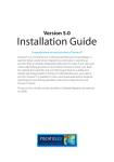
5.2.1 Create a Workspace
When you open BRATGUI, the software asks for the name and location of the ‘workspace’ you will be
working in. If one or more workspace already exists, the last used one is open by default. You can open
another one, or create a new one by choosing ‘new’ in the ‘workspace’ menu (leftmost menu).
Figure 1 Create a new workspace window
It is highly recommended to save the workspace (ctrl+s, or ‘save’ in the workspace menu) while
working. The workspace is otherwise saved when you quit BRATGUI (or, at least, the question of
whether you wish to save the workspace or not is asked then).
You can delete an existing workspace by choosing ‘delete’ in the ‘workspace’ menu, but note that you
can only work with BRATGUI within a workspace, and so have to create a new one if none exists.
4
Basic Radar Altimetry Toolbox User Manual
Other
-
items in the ‘Workspace’ menu are:
new
open: open a previously saved workspace
save: (or ctrl+s) save the current workspace and all its datasets, operations, formulas and
displays (views)
import: import all (datasets, operations, formulas and/or displays) of a previously saved
workspace
rename: rename the current workspace
delete: delete the current workspace
Recent workspaces: list the 2 most recently used workspaces
5.2.2 Create a dataset
First opened tab is ‘datasets’.
Figure 2: Create a new dataset
Choose ‘new’ in the ‘datasets’ menu if no dataset exists, or if you wish to work on other data than the
one already selected. The 'Name' dropdown list contains all the defined dataset names and allows the
dataset selection and renaming.
You can delete an existing dataset by choosing ‘delete’ in the ‘datasets’ menu, but note that you can only
work with BRATGUI with a dataset defined, and so have to create a new one if none exists.
5
Basic Radar Altimetry Toolbox User Manual
You have to give the dataset a name (with no space or special characters in the name). If you change
the name within the ‘name’ box, it renames your dataset.
Note that only coherent datasets are possible (i.e. same format, same data product). The ‘Check files’
button at the bottom of the window check this coherency.
Figure 3: A dataset. Left, the list of files; right (up) the list of available field within the selected file format, (bottom),
the description of the selected field as it appears in the data dictionary.
When you have created your dataset, and named it, you can then add files, chosen on your hard drive,
CD/DVD driver, local network… If you wish to add a long list of files, the ‘add dir’ button provides you the
possibility of choosing all the files within a directory.
‘Clear’ will empty the whole list. You can delete selected file(s) by using the ‘delete’ key on your
keyboard.
‘Up’, ‘Down’ and ‘Sort’ can be used to re-arrange the list. Files will be processed in this order. It can be
used to check for doublet, or missing files, or to remove unwanted files from a list.
In this tab,
• Left, you have the selected files’ names;
• Right, the list of all fields defined for this kind of data and, below, a more detailed description of
the
selected
field
(extracted
from
the
data
dictionary).
You can sort alphabetically the fields by clicking on ‘name’, ‘record’, ‘unit’, ‘format’, ‘dim’, at the
top of the box, or view a field which name begins by one or several letters by typing them, while
in this box.
6
Basic Radar Altimetry Toolbox User Manual
The list of all the fields of the currently selected file is divided into 6 columns:
- Name: the field short name
- Record: the record containing the field. Many files have 'header' and 'data' records while others
have much more (e.g. Envisat ones)
- Full name: the fully qualified name in the file structure hierarchy and related to the record.
- Unit: the unit of the field
- Format: the format of the field inside the file. In BRAT all fields are read as floating point values
(double).
- Dim: Dimension of the field (the number values of the indicated type in the field)
Under the list there is a text box which show a detailed description of the currently selected field (as
extracted from the data dictionary)
You can define as many dataset as you wish.
Note that if you want the same operation to be applied to several files separately, you will have to define
several datasets, or use the command files directly with a script (see section 7.3).
5.2.3 Create an operation
Second tab is ‘operations’.
Figure 4: Creating a new 'operation'
7
Basic Radar Altimetry Toolbox User Manual
If none exists, you have to create a new operation (name it as you prefer, with no space nor special
characters in the name). Choose ‘new’ in the ‘Operations’ menu.
You can delete an existing operation by choosing ‘delete’ in the ‘Operations’ menu, but note that you can
only process data with BRATGUI with an operation defined, and so have to create a new one if none
exists.
Otherwise, you can work with a previously saved operation. The 'Name' dropdown list contains all the
defined operations names and allows the operation selection and renaming. If you change the name
within the ‘name’ box, it renames your operation and erases the command file that was created with the
previous name (but not the output NetCDF file, if the operation was executed).
If you want to apply the same operation to different datasets, you have to re-create it as many time as
needed, or use the command files directly with a script (see section 7.3).
5.2.3.1 Data
Figure 5: Choosing a record within the selected dataset
Choose a dataset in the list of existing dataset to apply the operation to.
Choose a record within the dataset, where the data fields you’re interested in are. The description of
each field is given below when you click on a particular field.
The ‘F’ and ‘S’ button are used to insert a field in either the selected ‘data expression (F)’ or the selected
‘Select expression (S)’
8
Basic Radar Altimetry Toolbox User Manual
5.2.3.2 Created type
You can then choose if you prefer a ‘Y=F(X)’ or a ‘Z=f(X,Y)’ type of operation, i.e.:
- ‘Y=F(X)’,
if you wish to work with one – or several – field(s) with respect to another one;
typically,
this
leads
to
a
curve
kind
of
view.
It is the BRATCreateYFX program which will generates the output of the operation
- ‘Z=f(X,Y)’,
if you wish to work with one – or several – field(s) with respect to two others;
typically, with X=longitude and Y=latitude, this leads to a map (any field can be thus processed
with respect to any two others – but, for now, only maps are possible to display within BRAT).
It is the BRATCreateZFXY program which will generates the output of the operation
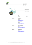
Figure 6: An 'Operations' tab when Z=F(X,Y) type is selected. Note the difference in the 'Data Expression box tabs
(at the middle of the window, see section 15.2.3.6): in Figure 5, above, only two tabs were available when Y=F(X)
was choosen (data field and X field). Here a third is visible, to define Y field.
9
Basic Radar Altimetry Toolbox User Manual
5.2.3.3 Data mode
Figure 7: Choice of the data mode
Data mode is used when you have several values of a field for a same (X) or (X,Y). This is typically the
case for:
- crossover points between tracks
- several files available for different dates
- sub-sample data
The possible values are:
- MEAN (default) : computes the mean over every values of the field within the dataset at each X
(or (X,Y))
- COUNT: returns the number of values of the field within the dataset at each X (or (X,Y))
- FIRST: returns the first encountered value of the field within the dataset (in the order of the list of
files as it appears in the ‘dataset’ tab)
- LAST: returns the last encountered value of the field within the dataset (in the order of the list of
files as it appears in the ‘dataset’ tab)
- MIN: gives the minimum value of the field within the dataset
- MAX: gives the maximum value of the field within the dataset
- STDDEV: computes the standard deviation over every values of the field within the dataset at
each X (or (X,Y))
Data mode can be used to compute statistics. They are also of use for the display (except for standard
deviation), if you prefer to visualise, e.g., the last value to the mean one.
10
Basic Radar Altimetry Toolbox User Manual
5.2.3.4 Functions
The 'Functions' area provides a simple way to include (and to know) the available functions and
constants which can be included in formulas. By default, no function is visible, but they appear in the
dropdown list if you click on it. For each function, if selected, you will see a short explanation of what it
does.
They are available to compute or select a data expression. See Annex A for more details about each
function.
Name
!
!=
&&
||
<
<=
==
>
>=
DV
PI
PI2
PI4
abs
ceil
cos
cosd
deg2rad
deg_normalize
dv
exp
floor
frac
iif
iif3
int
is_bounded
is_bounded_strict
is_default
log
log10
max
min
mod
rad2deg
round
sign
sin
sind
sqr
sqrt
tan
tand
to_date
Description
logical negation operator NOT
not-equal-to operator
The logical AND operator
logical OR operator
Less than
Less than or equal to
equal-to operator
Greater than
Greater than or equal to
Default value
PI value
PI/2 value
PI/4 value
Calculates the absolute value.
Calculates the ceiling of a value.
Calculates the cosine (radian) of a value.
Calculates the cosine (degree) of a value.
Translates Degree to Radian.
Normalizes longitude (degree)
Default value
Calculates the exponential.
Calculates the floor of a value
Calculates the fractional parts of a value.
Inline if
Inline if with default value case
Calculates the integer parts of a value.
Checks if a value x is included between two value (min/max)
Checks if a value x is stricly included between two value (min/max).
Checks if a value is a default value (1: yes, 0: no)
Calculates the logarithm of a value
Calculates the base-10 logarithm of a value
Calculates the larger of two values
Calculates the smaller of two values
Calculates the floating-point remainder
Translates Radian to Degree.
Calculates the rounded value
Checks the sign of a value (-1: negative, 1: positive or zero)
Calculates the sine (radian) of a value.
Calculates the sine (degreee) of a value.
Calculates the square of a value.
Calculates the square root of a value.
Calculates the tangent (radian) of a value.
Calculates the tangent (degree) of a value.
Translates a string value into a date value (expressed in seconds)
Typically, this can be used to translate a calendar date or julian day in seconds
11
Basic Radar Altimetry Toolbox User Manual
The ‘F’ and ‘S’ button are used to insert a function in either the selected ‘data expression (F)’ or the
selected ‘Select expression (S)’. The function will appear there with the correct syntax to be filled (e.g.
function(param1,param2); you will have to replace ‘param1’, ‘param2’ etc. by the fields or numbers you
wish to apply the function to).
You can use those functions for, e.g.:
- a test on a flag:
Surface_type == 0
will returns you only the ‘open ocean’ flagged Jason-1 GDR
data
- boundaries: is_bounded(-100,SSH,100) (or: (SSH >= -100) && (SSH <= 100))
5.2.3.5 Formula
In the Formula box, you will find pre-defined formulas (e.g. Sea Surface Height formulas from the
different satellites’ GDR fields), and also Data expressions or Selections previously saved by you within
the current workspace (or imported from another workspace).
The ‘F’ and ‘S’ button are used to insert a formula in either the selected ‘data expression (F)’ or the
‘Select expression (S)’. The formula will appear there either as an alias (if you leave the ‘as alias’
checked), or complete (if you un-check ‘as alias’).
Figure 8: use of a pre-defined formula (Envisat SSH),by its alias (top) and developed (bottom). Note the unit, put by
default at 'count', that you will have to change manually to ‘m’ (or a sub -unit of the metre)
5.2.3.6 Data expression
When your dataset and the type of operation are chosen, you have access to the definition of the Data
expression. You have two or three tabs (Fields, X, and Y), depending on the type of operation. The
dropdown list contains the names of all the expressions while the text box below allows the value of the
expression to be edited.
A data expression can be:
- only one field in a dataset (typically, for a map, longitude as x-axis, latitude as y-axis)
- a combination of fields, either +,-,* and /, or by using the available functions in the list right of the ‘data’
box (see 5.2.3.4).
- a pre-set combination of fields among the ones you will find in the ‘formulas’ box (see 5.2.3.5)
12
Basic Radar Altimetry Toolbox User Manual
Figure 9: A data expression box with a field included (one data field only to define this expression), in the Z=F(X,Y)
case. Note the Unit (default unit as defined in the dataset); if prefered, you could type in ‘m’ or ‘km’. The ‘New data
field’ button enables you to define more than one field to process with respect to the defined X and Y axis
Give a name to your data expression (let’s say, ‘my_first_field’). Note that if you change the name, it
renames your expression. This name will be the one that will be written by default on the plots, near to
the scale if you do not give a title to your field (in the options).
Type your expression (the name of one data field, or a combination of several ones of them) in the box
below. Alternatively, to appear in the same box, you can select either:
- a field within the dataset/record by selecting it in the list (you can sort the list alphabetically in
each column, or type in the first letters to find the right one), and then click on the ‘F’ button right
of the data fields list to have it inserted where your cursor was in the data expression box.
- or a ready-made expression by selecting it in the ‘formulas’ list, and then click on the ‘F’ button
right of the formulas box, or type in the alias.
Then click on ‘field options’. There you can type in a title for your field. The title will be displayed as
default name of the field in the plots (if no title, it is the data expression name).
If you choose a Z=F(X,Y) type, you can also choose to smooth and/or extrapolate by a Loess filter the
data so as to have a fully colored plot (and not individual tracks or points). In that case, you will have to
fill in the corresponding information in the X and Y fields, too.
Figure 10: Option for a data field in the Z=F(X,Y) case.
For the Y=F(X) case, only the top two boxes exist.
You can define as many fields as you wish, clicking on the ‘new data field’ button and repeating the
sequence above. Note that you must have at least one field defined. The choice of X and Y axis, and
their options, apply to all the fields within the current operation. You cannot choose (e.g.) different
resolutions for X and Y for different fields within the same operation. The data mode is also the same for
all the fields.
13
Basic Radar Altimetry Toolbox User Manual
Figure 11: A data expression box with a X field included, in the Z=F(X,Y) case. Note the Unit (default unit as
defined in the dataset) and the data type (used to define default values, min, step, and max).
For the choice of the field to use as X axis:
- click on the X ‘tab’,
- choose a name (‘my_x_axis’),
- enter your expression or choose it in the lists (same than for the field),
- click on ‘field options’. The option window enable you to choose
o the title of the axis,
If you choose a Z=F(X,Y) type, you can also choose :
o the minimum and maximum of the axis (typically, this can be used to define a
geographical sub-set)
o Step,
to
define
the
resolution (longitude-latitude)
of
the
output
file.
Default is 1/5°. However, note that the smallest the resolution, the longest the operation
will take to be executed.
o the ‘Loess cut-off’ value, i.e. the number of grid points before the Loess filter equals to
zero (odd number)
Figure 12: Option for a X field in the Z=F(X,Y) case. Note the min, max and step
Loess cut-off is used when a filter has been defined in the data field options.
For the Y=F(X) case, only the top two boxes (Name and Title) exist.
If you choose a Y=F(X) type, you can also choose the data type of the axis (lat, lon, time or X for any
other kind of data used as X axis)
Note that you must have one X axis defined
If relevant (Z=F(X,Y)), do the same also for the Y axis. Note that, if you choose Z=F(X,Y) you must have
one Y axis defined.
14
Basic Radar Altimetry Toolbox User Manual
Figure 13: A data expression box with a Y field included. Note the Unit (default unit as defined in the dataset) and
the data type (used to define default values, min, step, and max).
Figure 14: The dropdown list for a data expression with two data fields, one X field, one Y field
Beware of what is your unit (you need to have a valid unit, i.e. one that is defined in the data dictionary
as such). If you choose a pre-saved formula: a default ‘count’ will appear as unit. If you select one field in
the dataset list and insert it by using the ‘F’ button, it will be automatically filled with the correct unit (but if
you finally write your own formula, the final unit might be different). If the unit you defined does not fit the
unit of the data, an error will be generated (in the Log tab)
However, note that every operation is computed using SI units even if a sub-unit is defined for the data
(e.g. metres instead of cm, mm or km). Thus you can put ‘cm’ as unit even if the data are in mm, and
end with correct values.
Right of the Data expression box, Four buttons are available:
- Check, to check if the expression is well-formed, i.e. if the syntax is correct (but NOT if it is
scientifically or even dimensionally correct…).
- Save as: save the current data expression for future use within the workspace. It will then be
available in the ‘formulas’ box
- Reset empties the whole box
- Comment. The 'Comment' button allows associating a more detailed comment with the
expression (for convenience, it only appears as comments in files and is never used for
computing/viewing), for future reference
15
Basic Radar Altimetry Toolbox User Manual
Figure 15: A 'Comment' window. It can be used as a reminder of the expression and its meaning, and if need be, of
its unit for future use.
5.2.3.7 Select expression
This box is made to select data within the dataset: e.g. by date, boundaries, to make some data editing
or selection;
As there is only one selection expression, there is no dropdown list with the name, just the text box
which allows the value of the expression to be edited.
It is in this text area that fields/functions/formulas are inserted when clicking on the 'S' buttons.
A data measurement in the Dataset files is selected only if the result of this expression if not 0 and not a
missing/default value. Defining no selection expression is like selecting everything (the expression value
is '1')
Figure 16: A Selection expression (test on a 'flag' which value is 0 over open ocean)
Type in your selection expression. Alternatively, to appear in the same box, you can select either:
- a field within the dataset/record by selecting it in the list (you can sort the list alphabetically in each
column, or type in the first letters to find the right one), and then click on the ‘S’ button to have it inserted
where your cursor was in the selection expression box.
- or a ready-made expression by selecting it in the ‘formulas’ list, and then click on the ‘S’ button, or type
the alias.
Boolean operators are available, to combine the conditions.
16
Basic Radar Altimetry Toolbox User Manual
Figure 17: Another selection, using a formula alias, to edit values of SSH higher or lower than 100m. This
expression could also have been written ‘(%{ENVISAT_SSH} <= 100) && (%{ENVISAT_SSH}>= -100), where &&
is the boolean operator ‘AND’ (see function list for the complete list of operators)
The selection operates on all available fields within the dataset (you can put in that you wish your X field
between min & max, your Y one between min & max and, e.g. your field between -100 and 100).
Right of the Selection expression box, Four buttons are available:
- Check, to check if the expression is well-formed, i.e. if the syntax is correct (but NOT if it is
scientifically or even dimensionally correct…).
- Save as: save the current Selection expression for future use within the workspace. It will then be
available in the ‘formulas’ box
- Reset empties the whole box
- Comment. The 'Comment' button allows associating a more detailed comment with the
expression (for convenience, it only appears as comments in files and is never used for
computing/viewing), for future reference
5.2.3.8 Output
Output gives the name of the output (netCDF) file. It is predefined using the name you gave to your
operation, and cannot be changed within the GUI.
‘Execute’, down at the right, process the defined operation on the whole selected dataset.
You can execute several different operations at the same time (i.e. execute one while another is being
processed), or an operation and a view (provided you’re not trying to visualise the file you’re processing).
However, this will slow down each individual execution. You can see in the ‘Log’ tab the current tasks
being executed (both operations and views), the comments during execution (verbose mode) and the
errors. ‘Code 0’ indicates that the execution went OK.
5.2.4 Create a view
Third tab is ‘Views’.
If none exists, you have to create a new view (name it as you prefer, with no space nor special
characters in the name). Choose ‘new’ in the ‘Views’ menu.
The name is used to call the command file that will be executed to display the data, and if need be to
retrieve your view in the future. The 'Name' dropdown list contains all the defined views names and
allows the view selection and renaming.
You can delete an existing view by choosing ‘delete’ in the ‘Views’ menu, but note that you can only
visualise your data with BRATGUI with a view defined, and so have to create a new one if none exists.
17
Basic Radar Altimetry Toolbox User Manual
Figure 18: Create a view, to launch the visualisation tool
First thing after naming your view is to choose between ‘Y=F(X)’ and ‘Z=F(lon,lat)’
When it is done, you will have access in the ‘Data’ box to the available fields corresponding to either
choice (outputs from operations computed within the workspace). They are given by operation/file
name/field name. You can refresh the list to update it with respect to the latest operations.
In the ‘Data’ box, select one or several data fields by clicking on them (ctrl + click for several fields), and
use the arrow to switch it or them from ‘available’ (left) to ‘selected’ (right). X axis (and Y) has been predefined in the ‘operation’ tab.
You can give your display a title (just below the ‘name’ of the view).
18
Basic Radar Altimetry Toolbox User Manual
5.2.4.1 ‘Y=F(X)’
Figure 19: Example of a ‘views’ tab when Y=F(X) is chosen
For such a plot, you can define a sub-set to be plotted (by X min, X max, Y (=field) min, Y (=field) max)
If you click on one of the selected data field (right-hand list), you can see in the ‘Display field properties’
box below the name of the represented field is also given. By default, it is the title of the field given in the
‘options’ of the data expression, or the name of the field data expression.
‘Field group’ is used to group the selected fields – or not – in a same plot. Typically, if checked (default),
you will have each field as a curve of a given color overlaid in the same plot.
19
Basic Radar Altimetry Toolbox User Manual
5.2.4.2 ‘Z=F(lon,lat)’
Figure 20: Example of a ‘views’ tab when Z=F(lon,lat) is chosen
You can choose your projection in a list of pre-defined projection (it can be also changed in the
visualisation interface). Default is a 3D projection.
Group by file can be used to animate a series of maps. If you have several identical field names from
several operations (e.g. if you have computed the same field at different dates), if you check this option,
you will have access to the ‘animation toolbar’ in the visualisation interface.
If you click on one of the selected data field (right-hand list), you can see in the ‘Display field properties’
box below:
- the
name
of
the
represented
field.
By default, it is the title of the field given in the ‘options’ of the data expression, or the name of the
field data expression (if no title was given).
- A choice between ‘solid color’ and ‘contour’ representation. It is of course highly recommended to
choose at most two different fields to be displayed on the same plot, one represented in solid
colors, the other in contours, to be able to see something on the plot.
- Min and max of the color scale
- The color scale, among a pre-defined list of color scales, or in previously made and saved color
scale (see 6.2.2).
All those options can also be changed in the visualisation interface.
20
Basic Radar Altimetry Toolbox User Manual
‘Field group’ is used to group the selected fields – or not – in a same plot. Typically, if all fields have ‘1’
(default) you will have a color and a contour map plotted one overlaying the other. If you put a different
number for each field, you will have as many separate plot windows as you have typed numbers. The
difference with ‘group by file’ is that you will have adjacent plot (i.e. you can look at them at the same
time), not successive ones.
‘Execute’ will execute the request as it is in the defined view (request that is written in the command file
which name is shown left of the ‘execute’ button), and launch the visualisation tool (see chapter 6 for a
description of this interface). You can see in the ‘Log’ tab the current executions (both operations and
views), and the errors.
21
Basic Radar Altimetry Toolbox User Manual
6
Visualisation interface
The visualisation interface is called by executing a command file from the ‘views’ tab of the GUI. It can
also be used with a command file.
The visualisation options are quite different for an ‘Y=f(X)’ (curve) than for a ‘Z=F(lon,lat)’
6.1 ‘Y=F(X)’
Figure 21: An example Y=F(X) visualisation
In the ‘File’ menu, you can save your plot, in different image format (bmp – windows bitmap – jpeg, png,
pnm or tiff), or export it to gnuplot.
The ‘View’ menu enables you to display or not the right-hand panel with the properties.
22
Basic Radar Altimetry Toolbox User Manual
First tab (‘datasets’) recalls the name of the field
as it appears in the Display Field properties of the
‘Views’ tab.
When a field is selected in this ‘datasets’ tab, you
have some options to choose the color and style
(full, dots, etc.) of the line and of the points (none
by default, circles, crosses, etc.). If there are
several fields to plot, you can thus enhance the
legibility of your plot.
Second tab (‘properties’) enable to choose several
options (some being already available within the
‘views’ tab; however, modifications done only in
the visualisation window will not be saved as part
of the workspace, and thus cannot be recalled for
future use. We thus strongly recommend that you
choose options as min, max of both axis, units,
plot title and axis name within the Operations and
Views tabs.
Figure 22: Datasets tab of the visualisation tool
The label of each axis includes by default the name of the plotted
field, and its unit, with \n for line break and \t for space.
‘Fallback range’ enables you to select in a more restricted range
(e.g. you selected a whole ground track, but finally wish to look only
at a -10 + 10°N range.
You can also zoom in on a portion of curve using middle button of
your mouse.
‘Current range’ indicates the min max of your current view.
To go back to the first opened view, type on ‘r’.
Figure 23: Y-axis properties of a Y=F(X) plot, with only one field selected
for view. Label (including the unit), number of ticks in the axis, min and max
of the axis are shown. X-axis properties are similar.
23
Basic Radar Altimetry Toolbox User Manual
.Figure 24: Zoom of the same curve than above
6.2 ‘Z=F(lon, lat)’
Note that, even if Z=F(X,Y) with any data field as X and as Y is possible to process within the
‘operations’ tab, only the case Z=F(longitude, latitude) (i.e., a map) is possible for now in BRAT.
In the ‘File’ menu, you can save your plot, in different image format (bmp – windows bitmap – jpeg, png,
pnm or tiff), or export it to gnuplot.
The ‘View’ menu enables you
- display or not the right-hand panel with the properties.
- display the color bar or not
- display the animation toolbar (if relevant, i.e. if you are visualising a series of fields with the same
name, and chose the option ‘group by file’). Once in this toolbar, you can launch the animation of
the fields, stop it and control its speed.
- to open the color table editor and the contour table editor
Figure 25: Animation toolbar (available for a series of fields with the same name, option 'group by file' chosen). The
animation is available as visualisation (not to be saved). ‘Animate’ launch the animation, Reset reset the animation
to the first frame. The number after is the number of the frame. ‘Loop’ enables to loop the animation, and ‘Speed’ to
choose its speed (in frames per second).
24
Basic Radar Altimetry Toolbox User Manual
Figure 26: An example Z=F(lon, lat) visualisation, with default projection (3D) and the ‘Ozone’ color table
6.2.1 Display properties
Available display properties are:
- the projection. Several of them are available (see ‘Create a view’). You can change it on the fly,
even if you decided on another one in the ‘view’ tab of the GUI (but your choice won’t be saved)
25
Basic Radar Altimetry Toolbox User Manual
Figure 27: Same plot than above, but with a different projection (Plate Carree)
-
Centre point: define the centre of the display (only relevant for 2D maps, not for the ‘3D’
projection)
Data layers: lists the different fields visualised, and if each one is visualised as solid color or as
contours.
Edit open either the color table or the contour table editor (see section 6.2.2 and 6.2.3 below)
You can change your mind there with respect to what you defined previously (but, there also,
your choices won’t be saved). If two fields are overlaid, you can switch contours and color. That’s
why, in that case, you will have two color table in your plot (one for each field)
The number of label and the range define those for the color table.
26
Basic Radar Altimetry Toolbox User Manual
Figure 28: Visualisation with color and contour (for the same field)
-
View: 3 tabs are available
o State enables to save a particular display for the duration of the session, and to recall it by
its number.
Clear erases all the saved displays,
Full goes back to a full-sized view of the chosen area (if a zoom had been made)
o Zoom enables to visualise a specified area, defined by its longitude and latitude minimum
and maximum (this does not work on the ‘3D’ projection).
o Z-height, only available for the 3D projection enables to render field values at the surface
as bumpyness (radius gives the height, factor the scale factor).
6.2.2 Color table editor
Several color tables are available within BRAT.
You can use any one of them. You can also make your own color table.
27
Basic Radar Altimetry Toolbox User Manual
Figure 29: The color table editor, with the list of predefined tables
In the ‘File’ menu of the color table editor, ‘Load color table’ load a previously made color table.
Recent color table recall recently used ones,
and ‘save as’ to save the one you’ve just done.
The ‘Edit’ menu enables to change the number of color within an existing color table, and the
interpolation between the different colors.
The ‘Mode’ menu enables to choose between predefined color tables, two-color gradient color tables or
multi-color gradient color tables.
6.2.2.1 two-color gradient color tables
The two-color gradient color table editor enables to make a color table by defining its first and last colors.
Colors are defined by their Red, Green and Blue components and Alpha channel (for transparency).
Default
is
black
(RGB=0,0,0)
for
both,
and
no
transparency
(A=255).
You can click on ‘apply’ to look at the way it shows on your plot. When you are satisfied of your color
table, you can save it, and recall it in future sessions.
28
Basic Radar Altimetry Toolbox User Manual
Figure 30: Two-color gradient color table editor
6.2.2.2 Multi-color gradient color tables
The multi-color gradient colot table editor works much as the two-color one, except that you have to
define not only the first and last values, but that you can also define intermediate one(s).
Definition of the colors is the same (Red, Green, Blue + Alpha channel), and you also have a cursor
beneath the preview of the table that enables you to place your new color in the range.
To add a new color, click on ‘0’ in the ‘X-values’ list, then on ‘Insert color’. You will then have a new value,
‘1’, that you can change by moving the cursor. When you have placed your new value in the range,
define your color. Repeat the operation a many time as you wish to add colors. Note that you do not
have to define 255 colors (if you want a 255-color table) one by one, since the software interpolates
between the values you are giving, so choosing 5 or 7 of them is usually a maximum.
You can click on ‘apply’ to look at the way it shows on your plot. When you are satisfied of your color
table, you can save it, and recall it in future sessions.
29
Basic Radar Altimetry Toolbox User Manual
Figure 31: Multi-color gradient color table editor. When first opening it (left), and after defining 5 colors over the
whole range ; equally distributed.
6.2.3 Contour table editor
The contour table editor enable you to choose the range and number of contours that you wish to see on
your plot, the width and color of the lines, and if you want labels on the contours or not, and their style if
so.
Note that your contour table cannot be saved and re-used for future use.
30
Basic Radar Altimetry Toolbox User Manual
Figure 32: Contour table editor
31
Basic Radar Altimetry Toolbox User Manual
7 Using BRAT as commands
The GUI is there to ease the use of BRAT. However, everything made with the GUI can be made directly
by writing command files and execute them and more than what can be done with the GUI is possible
with command files.
Dictionaries of key functions that can be called within command file are available in Annex B (Y=F(X),
Annex C (Z=F(X,Y) and Annex D (Display command file keys).
7.1 Creating an output NetCDF file
A ‘Create’ command file typically consist in
- the definition of a dataset (list of files that will be processed),
- the name of the record within this dataset where the data you are interested in are stored,
- then the definition of an X axis and of one or several ‘Field(s)’; in the Z=F(X,Y) case, also the definition
of an Y-axis,
- a selection expression, if need be
- the name and localisation of the NetCDF output file
The definition of the axis or of a field include the name of an existing data field, or the expression that
you wish to compute from several of them, a name (with no space nor special characters), a unit, a title
(that can have space or special characters), a min and a max, and information about a possible filter (
#----- GENERAL PROPERTIES ----DATA_MODE=MEAN
#----- DATASET ----RECORD=ra2_mds
FILE=File1
FILE=File2
…
#----- FIELDS ----Y=lat
Y_NAME=lat
Y_TYPE=Latitude
Y_UNIT=degrees_north
Y_TITLE=Latitude
Y_FILTER=DV
Y_MIN=DV
Y_MAX=DV
Y_INTERVALS=DV
Y_LOESS_CUTOFF=DV
X=lon
X_NAME=lon
X_TYPE=Longitude
X_UNIT=degrees_east
X_TITLE=Longitude
X_FILTER=DV
X_MIN=DV
X_MAX=DV
X_INTERVALS=DV
X_LOESS_CUTOFF=DV
FIELD=ra2_wind_sp
FIELD_NAME=my_first_field
FIELD_TYPE=Data
FIELD_UNIT=mm/s
32
Basic Radar Altimetry Toolbox User Manual
FIELD_TITLE=Altimeter wind speed modulus
FIELD_FILTER=DV
FIELD_MIN=DV
FIELD_MAX=DV
FIELD_INTERVALS=DV
FIELD_LOESS_CUTOFF=DV
FIELD=alt_cog_ellip - ku_band_ocean_range - mod_dry_tropo_corr - inv_barom_corr (tot_geocen_ocn_tide_ht_sol1 + tidal_load_ht + long_period_ocn_tide_ht) solid_earth_tide_ht - geocen_pole_tide_ht - sea_bias_ku - ra2_ion_corr_ku mwr_wet_tropo_corr
FIELD_NAME=SSH
FIELD_TYPE=Data
FIELD_UNIT=m
FIELD_TITLE=my second field
FIELD_FILTER=DV
FIELD_MIN=DV
FIELD_MAX=DV
FIELD_INTERVALS=DV
FIELD_LOESS_CUTOFF=DV
#----- SELECT -----
#----- OUTPUT ----OUTPUT=output_file.nc
Example command file to create a Z=F(X,Y) output
You create the NetCDF file by typing
‘BratCreateZFXY.exe command_file.cmd’
(or ‘BratCreateYFX.exe command_file.cmd’ )
You’ll then have a NetCDF file that you can either visualise through the tool provided within BRAT, or
with some other tools reading NetCDF.
7.2 Visualising an output NetCDF file through BRAT
To visualise an output file, you have to write a second command file.
This kind of file is simpler than the one needed to create a NetCDF.
Basically, the needed commands are:
- the name of the file(s) to be displayed
- the tile, projection
- The name of the field(s) to be displayed
- And some information about the display (min, max, name, contour or not, color table…)
#!/usr/bin/env BratCreateZFXY
#Type:Z=F(X,Y)
#----- DATASET ----FILE=Createenvisat_cycle.nc
#----- GENERAL PROPERTIES ----DISPLAY_TITLE=title of the plot
DISPLAY_GROUPBY_FILE=Y
DISPLAY_PROJECTION=3D
33
Basic Radar Altimetry Toolbox User Manual
#----- sigma_0_ku FIELD ----FIELD=sigma_0_ku
#----- sigma_0_ku FIELDS PROPERTIES ----DISPLAY_NAME=sigma_0_ku
FIELD_GROUP=1
DISPLAY_MINVALUE=0.00000
DISPLAY_MAXVALUE=50.000
DISPLAY_CONTOUR=N
DISPLAY_SOLID_COLOR=Y
DISPLAY_COLORTABLE=DV
Example ‘display’ command file
You open the visualisation tool by typing:
‘BratDisplay.exe command_file.cmd’
7.3 Using the command files to process many datasets
A typical case when using the command files will be much easier than using the GUI is when you will
want to process the same operation on all or a long series of altimetry satellite cycles. Command files
enable you to write a script that will process the same operation on a number of files.
You can either write directly the command file, or you can make the command file through the GUI, test it
on one cycle, and then modify it (right-click) by replacing the cycle number by a character that will be
replaced consecutively by a list of cycle number through a script;
#!/usr/bin/env BratCreateZFXY
# SRC_DATA_DIR and CYCLE are environment variables that can be set in a shell #
script
FILE=${SRC_DATA_DIR}/JA1_GDR_2PAP${CYCLE}_001.CNES
FILE=${SRC_DATA_DIR}/JA1_GDR_2PAP${CYCLE}_002.CNES
FILE=${SRC_DATA_DIR}/JA1_GDR_2PAP${CYCLE}_003.CNES
RECORD = data
VERBOSE = 2
ALIAS_NAME = SLA_JASON
ALIAS_VALUE = altitude - range_ku - model_dry_tropo_corr - inv_bar_corr (ocean_tide_sol1 + ocean_tide_equil + load_tide_sol1) - solid_earth_tide - pole_tide
- sea_state_bias_ku - iono_corr_alt_ku - rad_wet_tropo_corr - mss
X
= longitude
X_TYPE
= longitude
X_NAME
= Longitude
X_UNIT
= DV
X_TITLE
= Longitude
X_MIN
= DV
X_MAX
= DV
X_INTERVALS = 1800
Y
= latitude
Y_TYPE
= latitude
Y_NAME
= Latitude
Y_UNIT
= DV
Y_TITLE
= Latitude
Y_MIN
= DV
Y_MAX
= DV
Y_INTERVALS = 900
34
Basic Radar Altimetry Toolbox User Manual
# SLA_JASON is an alias see ALIAS_NAME and ALIAS_VALUE above
FIELD = %{SLA_JASON}
FIELD_TYPE = data
FIELD_NAME = SLA
FIELD_UNIT = m
FIELD_TITLE = Sea Level Anomalies - Cycle ${CYCLE}
FIELD_FILTER
= LOESS_EXTRAPOLATE
X_LOESS_CUTOFF
= 5
Y_LOESS_CUTOFF
= 5
SELECT = is_bounded(-1.0, %{SLA_JASON},1.0)
OUTPUT
OUTPUT_TITLE
= ${BRATHL_DATA_DIR}/JasonSLA${CYCLE}.nc
= Jason - Cycle ${CYCLE}
An example command file to create output NetCDF for several cycles (SLA from Jason-1 GDRs)
REM Set the cycle number
SET CYCLE=109
REM Set the data source path
SET SRC_DATA_DIR=D:\data\gdr_jason\cycle_%CYCLE%
REM Launch 'Brat create Z=F(X,Y)' process
BratCreateZFXY C:\BRAT\MyCmdPath\BratCreateZFXYJasonSLASample.cmd
REM -----------------------------REM Set another cycle number
SET CYCLE=110
REM Set the data source path
SET SRC_DATA_DIR=D:\data\gdr_jason\cycle_%CYCLE%
REM Launch 'Brat create Z=F(X,Y)' process
BratCreateZFXY C:\BRAT\MyCmdPath\BratCreateZFXYJasonSLASample.cmd
An example script for DOS (to be inserted in a .bat file) to launch a command file over several cycles
#!/bin/bash
# BratCreateZFXYJasonSLASample.sh
# Set the cycle number
export CYCLE=109
# Set the data source path
export SRC_DATA_DIR=/data/gdr_jason/cycle_%CYCLE%
# Launch 'Brat create Z=F(X,Y)' process
BratCreateZFXY BRAT/MyCmdPath/BratCreateZFXYJasonSLASample.cmd
# -----------------------------# Set the cycle number
export CYCLE=110
# Set the data source path
export SRC_DATA_DIR=/data/gdr_jason/cycle_%CYCLE%
# Launch 'Brat create Z=F(X,Y)' process
BratCreateZFXY BRAT/MyCmdPath/BratCreateZFXYJasonSLASample.cmd
An example Shell script for Linux to launch a command file over several cycles
35
Basic Radar Altimetry Toolbox User Manual
8 BRAT Application Programming Interfaces (APIs)
Some functions of BRAT are not available through the GUI, but through IDL and Matlab APIs.
8.1 Data reading function
BRATHL_READDATA read data from a set of files; each measure for a data is a scalar value (a single
number)
Possible arguments of this function are:
[in] fileNames: file name string (one file) or file names array
[in] recordName: Name of the fields record (for netCdf files recordName is 'data')
[in] selection: Expression involving data fields which has to be true to select returned data. (if empty
string no selection is done (all data is selected)
[in] dataExpressions: Expression string (one expression) or expressions array applied to data fields to
build the wanted value.
[in] units: Wanted unit for each expression (string (one unit) or units array).
(if empty string, no unit conversion is applied to the data of the corresponding expression.
When a unit conversion has to be applied, the result of the expression is considered to be the
base unit (SI). For example if the wanted unit is gram/l, the unit of the expression is supposed
to be kilogram/m3 (internaly all data are converted to base unit of the actual fields unit which is
coherent with the above assumption).
[in/out] results: Data read. Must be an array (dim = number of dataExpressions) to values to read.
[in] ignoreOutOfRange: Skip excess data. 0=false, other = true
Must be false if statistics is true.
[in] statistics: returns statistics on data instead of data themselves
0=false, other = true
If statistics is true, ignoreOutOfRange must be false.
The returned values (5 values) for each expression are:
- Count of valid data taken into account.
Invalid data are those which are equal to the default/missing value
- Mean of the valid data.
- Standard deviation of the valid data
- Minimum value of the valid data
- Maximum value of the valid data
[in] defaultValue: value to use for default/missing values
This is the value you want to indicate that a value is missing or invalid.
return 0 or error code.
Syntax: see Annex E (IDL)
8.2 Cycle/date conversion functions
Two functions are available to convert between cycle/pass and date.
Syntax: see Annex E (IDL)
BRATHL_CYCLE2YMDHMSM
Converts a cyle/pass into a date
Arguments of this function are:
[in] mission :
0 : Topex/Poseidon
1 : Jason-1
36
Basic Radar Altimetry Toolbox User Manual
2 : ERS2
3 : Envisat
4 : ERS1-A
5 : ERS1-B
6 : GFO
[in] cycle : number of cycle
[in] pass : number of pass in the cycle
Outputs are:
[out] dateYMDHMSM : date to convert
BRATHL_YMDHMSM2CYCLE
Converts a date into a cycle/pass
Arguments of this function are:
[in] mission : mission type :
0 : Topex/Poseidon
1 : Jason-1
2 : ERS2
3 : Envisat
4 : ERS1-A
5 : ERS1-B
6 : GFO
[in] dateYMDHMSM : date to convert
Outputs are:
[out] cycle : number of cycle
[out] pass : number of pass in the cycle
8.3 Date conversion/computation functions
A set
-
of functions is available to convert between the different kinds of date formats:
days-seconds-microseconds dates:
Julian decimal dates:
year, month, day, hour, minute, second, microsecond dates:
Syntax: see Annex E (IDL)
BRATHL_DAYOFYEAR
Retrieves the day of year of a date
BRATHL_NOWYMDHMSM
Gets the current date/time
BRATHL_SETREFUSER1
BRATHL_SETREFUSER2
Set user-defined reference dates
Set user-defined reference dates
BRATHL_DIFFDSM
Computes the difference between two days-seconds-microseconds
dates (date1 - date2)
the result is expressed in a decimal number of seconds
Computes the difference between two decimal julian dates (date1 date2)
the result is expressed in a decimal number of seconds
Computes the difference between two year, month, day, hour,
minute, second, microsecond dates (date1 - date2)
the result is expressed in a decimal number of seconds
BRATHL_DIFFJULIAN
BRATHL_DIFFYMDHMSM
BRATHL_DSM2JULIAN
Converts a days-seconds-microseconds date into a decimal julian
date, according to refDate parameter
37
Basic Radar Altimetry Toolbox User Manual
BRATHL_DSM2SECONDS
BRATHL_DSM2YMDHMSM
BRATHL_JULIAN2DSM
BRATHL_JULIAN2SECONDS
BRATHL_JULIAN2YMDHMSM
BRATHL_SECONDS2DSM
BRATHL_SECONDS2JULIAN
BRATHL_SECONDS2YMDHMSM
BRATHL_YMDHMSM2DSM
BRATHL_YMDHMSM2JULIAN
BRATHL_YMDHMSM2SECONDS
Converts a days-seconds-microseconds date into seconds,
according to refDate parameter
Converts a days-seconds-microseconds date into a year, month,
day, hour, minute, second, microsecond date
Converts a decimal julian date into a days-seconds-microseconds
date, according to refDate parameter
Converts a decimal julian date into seconds, according to refDate
parameter
Converts a decimal julian date into a year, month, day, hour, minute,
second, microsecond date
Converts seconds into a days-seconds-microseconds date,
according to refDate parameter
Converts seconds into a decimal julian date, according to refDate
parameter
Converts seconds into a a decimal julian date, according to refDate
parameter
Converts a year, month, day, hour, minute, second, microsecond
date into a days-seconds-microseconds date, according to refDate
parameter
Converts a year, month, day, hour, minute, second, microsecond
date into a decimal julian date, according to refDate parameter
Converts a year, month, day, hour, minute, second, microsecond
date into a seconds, according to refDate parameter
8.4 Named structures
Several structures are also available, to represent the different kinds of date formats
Syntax: see Annex E (IDL)
BRATHL_DATEYMDHMSM
YYYY-MM-DD HH:MN:SS:MS date structure
YEAR
MONTH
DAY
HOUR
MINUTE
SECOND
MUSECOND
BRATHL_DATEDSM
day/seconds/microseconds date structure
REFDATE
reference date
DAYS numbers of days
SECONDS numbers of seconds
MUSECONDS
numbers of microseconds
REFDATE is the reference date i.e :
0: 1950-01-01 00:00:00.0
1: 1958-01-01 00:00:00.0
2: 1985-01-01 00:00:00.0
3: 1990-01-01 00:00:00.0
4: 2000-01-01 00:00:00.0
5: user reference 1
6: user reference 2
values of 5 and 6 allow the user to set two specifics reference date
38
Basic Radar Altimetry Toolbox User Manual
of his choice (see BRATHL_SETREFUSER1 and
BRATHL_SETREFUSER2 functions)
BRATHL_DATESECOND
decimal seconds date structure
REFDATE
reference date - see :BRATHL_DATEDSM
NBSECONDS
decimal numbers of seconds
(seconds.microseconds)
BRATHL_DATEJULIAN
decimal julian date structure
REFDATE
reference date - see :BRATHL_DATEDSM
JULIAN
decimal julian day
39
Basic Radar Altimetry Toolbox User Manual
Annex A Function lists and syntax
NOTE: Every expression involving a default value (also called missing value) is a default value. A true
expression is an expression which is not 0 and not a default value. The descriptions below are for
expressions which do not contain default value (to simplify their writing). For example the result of ‘A || B’
(A or B) is a default value if B is one even if A is true. There is two exceptions to this: is_default and iif3
which are the only way to check for default values.
Name
!
Description
The logical negation operator (!) reverses the meaning
of its operand.
The result is true if the converted operand is false; the
result is false if the converted operand is true.
!=
The not-equal-to operator (!=) returns true if the
operands do not have the same value; otherwise, it
returns false
&&
The logical AND operator (&&) returns the boolean
value true if both operands are true and returns false
otherwise.
Logical AND has left -to-right associativity.
<
Less than
It yields values of Boolean type. The value returned is
false (0) if the relationship in the expression is false;
otherwise, the value returned is true (1).
<=
Less than or equal to
It yields values of Boolean type. The value returned is
false (0) if the relationship in the expression is false;
otherwise, the value returned is true (1).
==
The equal-to operator returns true (1) if both operands
have the same value; otherwise, it returns false (0).
>
Greater than
It yields values of Boolean type. The value returned is
false (0) if the relationship in the expression is false;
otherwise, the value returned is true (1).
>=
Greater than or equal to
It yields values of Boolean type. The value returned is
false (0) if the relationship in the expression is false;
otherwise, the value returned is true (1).
DV
Default value
PI
PI value
PI2
PI/2 value
PI4
PI/4 value
abs
Calculates the absolute value.
ceil
Calculates the ceiling of a value.
cos
Calculates the cosine (radian) of a value.
cosd
Calculates the cosine (degree) of a value.
deg2rad
Translates Degree to Radian.
deg_normalize Normalizes longitude (degree)
dv
exp
floor
frac
iif
Default value
Calculates the exponential.
Calculates the floor of a value
Calculates the fractional parts of a value.
Inline if
If the first parameter is true (not 0 and not default
value),
the second parameter is returned, otherwise it is the
Syntax
expr1 ! expr2
Type
boolean
expr1 != expr2
boolean
expr1 && expr2
boolean
arithmetic expr1
< arithmetic
expr2
relational
operators
arithmetic expr1
<= arithmetic
expr2
relational
operators
==
relational
operators
relational
operators
arithmetic expr1
> arithmetic
expr2
arithmetic expr1
>= arithmetic
expr2
relational
operators
DV
PI
PI2
PI4
abs(param1)
ceil(param1)
cos(param1)
cosd(param1)
deg2rad(param1)
deg_normalize(p
aram1, param2)
DV
exp(param1)
floor(param1)
frac(param1)
iif(param1,
param2, param3)
number
number
number
number
conversion
conversion
number
40
Basic Radar Altimetry Toolbox User Manual
iif3
int
is_bounded
is_bounded_st
rict
third one.
Logically equivalent to:
if (param1 is true)
return param2
else
return param3
end if
Inline if with default value case
If the first parameter is true (not 0 and not default
value),
the second parameter is returned. If is is 0, the third
one is
returned, otherwise (it is a default value) the fourth
one is
returned
Logically equivalent to:
if (param1 is default value)
return param4
else
if (param1 is true)
return param2
else
return param3
end if
end if
Calculates the integer parts of a value.
Checks if a value x is included between two value
(min/max). is_bounded(min, x, max)
is_default
Checks if a value x is stricly included between two
value (min/max).
is_bounded_strict(min, x, max)
Checks if a value is a default value (1: yes, 0: no)
log
log10
max
Calculates the logarithm of a value
Calculates the base-10 logarithm of a value
Calculates the larger of two values
min
Calculates the smaller of two values
mod
Calculates the floating-point remainder
rad2deg
round
sign
Translates Radian to Degree.
Calculates the rounded value
Checks the sign of a value (-1: negative, 1: positive or
zero)
Calculates the sine (radian) of a value.
Calculates the sine (degreee) of a value.
Calculates the square of a value.
Calculates the square root of a value.
Calculates the tangent (radian) of a value.
Calculates the tangent (degree) of a value.
Translates a string value into a date value
Allowed format are:
YYYY-MM-DD HH:MN:SS.MS string.
For instance:
'1995-12-05 12:02:10.1230'
'1995-12-05 12:02:10'
sin
sind
sqr
sqrt
tan
tand
to_date
iif3(param1,
param2, param3,
param4)
int(param1)
is_bounded(para
m1,param2,para
m3)
is_bounded_strict
(param1,param2,
param3)
is_default(param
1)
log(param1)
log10(param1)
max(param1,par
am2)
min(param1,para
m2)
mod(param1,par
am2)
rad2deg(param1) conversion
round(param1)
sign(param1)
sin(param1)
sind(param1)
sqr(param1)
sqrt(param1)
tan(param1)
tand(param1)
to_date(param1)
conversion
41
Basic Radar Altimetry Toolbox User Manual
'1995-12-05'
a julian string: format:positive 'Days Seconds
Microseconds'
Seconds must be stricty less 86400 and
Microseconds must be stricty less than 1000000
For instance:
'2530 230 4569'
a julian string: format:positive decimal julian day
For instance:
'850.2536985'
For julian string, it can contain its reference date at
the end by specifying @YYYY where YYYY is the
reference year that's must be one of 1950, 1958,
1985, 1990, 2000
The reference year YYYY stands for YYYY-01-01
00:00:00.0
If no reference date is specified the default reference
date (1950) is used.
For instance:
'2530 230 4569@2000'
'850.2536985@1990'
'850.2536985@1950' is equal to '850.2536985'
||
Dates prior to 1950-01-01 00:00:00.0 are invalid
The logical OR operator (||) returns the boolean value
true if either or both operands is true and returns false
otherwise.
Logical OR has left-to-right associativity
expr1 || expr2
boolean
42
Basic Radar Altimetry Toolbox User Manual
Annex B Y=F(X) command file keys
NOTE: A help on command file keywords can be obtained by: “BratCreateYFX –k ”
FILE
RECORD
OUTPUT
OUTPUT_TITLE
SELECT
FIELD
FIELD_NAME
FIELD_TYPE
FIELD_UNIT
FIELD_TITLE
DATA_MODE
X
X_NAME
X_TYPE
X_UNIT
X_TITLE
ALIAS_NAME
ALIAS_VALUE
VERBOSE
Type : Str
Count : [1-n]
Input file name.
Type : Str
Count : 1
Record set name to take into account for a file.
Type : Str
Count : 1
Name of created/modified file.
Type : Str
Count : [0-1]
Title of created/modified file (string describing the
content and which should appear as a graphic title,
for example).
(Default="")
Type : Expr Count : [0-n]
True for record values selected.
(Default=1)
Type : Expr Count : [1-20]=X
Expression of fields of *RECORD* to take into account.
Type : Name Count : X
Name of the *FIELD* data
Type : KW1 Count : X
Type of *FIELD* data.
Type : Unit Count : X
Unit of *FIELD* expression.
Type : Str
Count : X
Long name describing *FIELD*. The one which should
appear in graphics on axis or legends, for example.
Type : KW2 Count : [0-1]
Keyword to indicate how data are stored/computed.
(Default=MEAN)
Type : Expr Count : 1
Expression of fields of *RECORD* to take into account.
Type : Name Count : 1
Name of the *X* data
Type : KW1 Count : 1
Type of *X* data (normally X, T or longitude).
Type : Unit Count : 1
Unit of *X* expression
Type : Str
Count : 1
Long name describing *X*. The one which should appear
in graphics on axis or legends, for example.
Type : Name Count : [0-n]=N
Name of an alias. An alias is a value which can be used
anywhere in another value of field by mean of
%{NAME} construct. Names are case sensitive.
If a name reference (%{XXX}) does not correspond to
an actually defined alias, the expansion is an empty
string.
(Default=None)
Type : Str
Count : N
The value of the alias. ALIAS_VALUE keyword must have at
least as many occurences as the ALIAS_NAME one.
Type : Int
Count : [0-1]
Amount of output: 0=None...5=Debug.
(Default=0)
43
Basic Radar Altimetry Toolbox User Manual
=====================
Description of types:
Name
Int
Expr
Str
Unit
KW1
KW2
String beginning with a letter and containing only letters,
digits and '_'
Integer
Combination of fields of the current record.
An expression which can contain function calls like
trigonometric, conversion, test...
String. Leading and trailing blanks are ignored.
Unit string conforming to Udunits package and the special
keyword 'DATE' which means that the data is a date.
Keywords: X/Y/Z/T/Latitude/Longitude/Data
Keywords: FIRST/LAST/MIN/MAX/MEAN/STDDEV/COUNT
44
Basic Radar Altimetry Toolbox User Manual
Annex C Z=F(X,Y) command file keys
NOTE: A help on command file keywords can be obtained by: “BratCreateZFXY –k ”
FILE
Type : Str
Count : [1-n]
Input file name.
OUTPUT
Type : Str
Count : 1
Name of created/modified file.
OUTPUT_TITLE Type : Str
Count : [0-1]
Title of created/modified file (string describing the
content and which should appear as a graphic title,
for example).
(Default="")
SELECT
Type : Expr Count : [0-n]
True for record values selected.
(Default=1)
RECORD
Type : Str
Count : 1
Record set name to take into account for a file.
DATA_MODE
Type : KW2 Count : [0-1]
Keyword to indicate how data are stored/computed.
(Default=MEAN)
POSITION_MODE Type : KW3 Count : [0-1]
How position is computed.
(Default=NEAREST)
OUTSIDE_MODE Type : KW4 Count : [0-1]
How data outside limits are managed.
(Default=STRICT)
X
Type : Expr Count : 1
Expression of fields of *RECORD* to take into account.
X_NAME
Type : Name Count : 1
Name of the *X* data
X_TYPE
Type : KW1 Count : 1
Type of *X* data (normally X, T or longitude).
X_UNIT
Type : Unit Count : 1
Unit of *X* expression
X_TITLE
Type : Str
Count : 1
Long name describing *X*. The one which should appear
in graphics on axis or legends, for example.
X_INTERVALS
Type : Int
Count : 1
Number of intervals between Min and Max for *X*.
(Default=180 for lat 360 for lon)
X_MIN
Type : Flt
Count : 1
Min value for *X* expression storage.
(Default=-90 for lat, -180 for lon)
X_MAX
Type : Flt
Count : 1
Max value for *X* expression storage.
(Default=90 for lat, 180 for lon)
X_LOESS_CUTOFF
Type : Int
Count : 1
Distance (in dots) where LOESS filter reaches 0 along
X axis. Must be an odd integer. If 1 or 0, Distance
computation is disabled. Needed only if at least
one filter is asked.
(Default=0)
Y
Type : Expr Count : 1
Expression of fields of *RECORD* to take into account.
Y_INTERVALS
Type : Int
Count : 1
Number of intervals between Min and Max for *Y*.
(Default=180 for lat 360 for lon)
Y_NAME
Type : Name Count : 1
45
Basic Radar Altimetry Toolbox User Manual
Name of the *Y* data.
Type : KW1 Count : 1
Type of *Y* data (normally X, T or longitude).
Y_UNIT
Type : Unit Count : 1
Unit of *Y* expression.
Y_TITLE
Type : Str
Count : 1
Long name describing *Y*. The one which should appear
in graphics on axis or legends, for example.
Y_MIN
Type : Flt
Count : 1
Min value for *Y* expression storage.
(Default=-90 for lat, -180 for lon)
Y_MAX
Type : Flt
Count : 1
Max value for *Y* expression storage.
(Default=90 for lat, 180 for lon)
Y_LOESS_CUTOFF
Type : Int
Count : 1
Distance (in dots) where LOESS filter reaches 0 along
Y axis. Must be an odd integer. If 1 or 0, Distance
computation is disabled. Needed only if at least
one filter is asked.
(Default=0)
FIELD
Type : Expr Count : [1-20]=X
Expression of fields of *RECORD* to take into account.
FIELD_NAME
Type : Name Count : X
Name of the *FIELD* data
FIELD_TYPE
Type : KW1 Count : X
Type of *FIELD* data.
FIELD_UNIT
Type : Unit Count : X
Unit of *FIELD* expression.
FIELD_TITLE
Type : Str
Count : X
Long name describing *FIELD*. The one which should
appear in graphics on axis or legends, for example.
FIELD_FILTER
Type : KS1
Count : X
How to filter the data.
ALIAS_NAME
Type : Name Count : [0-n]=N
Name of an alias. An alias is a value which can be used
anywhere in another value of field by mean of
%{NAME} construct. Names are case sensitive.
If a name reference (%{XXX}) does not correspond to
an actually defined alias, the expansion is an empty
string.
(Default=None)
ALIAS_VALUE
Type : Str
Count : N
The value of the alias. ALIAS_VALUE keyword must have at
least as many occurences as the ALIAS_NAME one.
VERBOSE
Type : Int
Count : [0-1]
Amount of output: 0=None...5=Debug.
(Default=0)
Y_TYPE
=====================
Description of types:
Name
Flt
Int
Expr
Str
String beginning with a letter and containing only letters,
digits and '_'
Floating point number
Integer
Combination of fields of the current record.
An expression which can contain function calls like
trigonometric, conversion, test...
String. Leading and trailing blanks are ignored.
46
Basic Radar Altimetry Toolbox User Manual
Unit
KW1
KW2
KW3
KW4
KS1
Unit string conforming to Udunits package and the special
keyword 'DATE' which means that the data is a date.
Keywords: X/Y/Z/T/Latitude/Longitude/Data
Keywords: FIRST/LAST/MIN/MAX/MEAN/STDDEV/COUNT
Keywords: EXACT/NEAREST
EXACT: Measures which are exactly on boundaries
(grid lines) are keeped others are ignored
NEAREST: Get the nearest boundary.
Keywords: STRICT/RELAXED/BLACK_HOLE
STRICT: Measure outside limits are ignored
RELAXED: Measure outside limits are ignored if
they are farther than a half step from
the limit.
BLACK_HOLE: Everything outside the limit is
considered to be on the limit.
Set of keywords from: NONE, LOESS_SMOOTH, LOESS_EXTRAPOLATE,
LOESS (LOESS means LOESS_SMOOTH and LOESS_EXTRAPOLATE)
47
Basic Radar Altimetry Toolbox User Manual
Annex D Display command file keys
NOTE: A help on command file keywords can be obtained by: “BratDisplay –k ”
FILE
Type : Str
Count : [1-n]
Input file name.
FIELD
Type : Expr Count : [1-23]=X
Expression of fields of *RECORD* to take into account.
FIELD_GROUP
Type : Int
Count : X
Group id from where belongs *FIELD*. generally used to
group many fields in one plot.
DISPLAY_PROPERTIES Type : Bool Count : [0-1]
Indicates if property panel is shown.
(Default=No)
DISPLAY_TITLE Type : Str
Count : [0-1]
Title of the plot to be displayed.
(Default="")
DISPLAY_ANIMATIONBAR Type : Bool Count : [0-1]
Keyword to indicate if property panel is shown.
(Default=No)
DISPLAY_COLORBAR
Type : Bool Count : [0-1]
Keyword to indicate if color bar (legend) is shown.
(Default=Yes)
DISPLAY_CENTERLAT
Type : Flt
Count : [0-1]
Latitude of the projection's center point.
(Default=0)
DISPLAY_CENTERLON
Type : Flt
Count : [0-1]
Longitude of the projection's center point.
(Default=0)
DISPLAY_PROJECTION Type : KW9
Count : [0-1]
Projection to use for mapping the world globe.
(Default=3D)
DISPLAY_COASTRESOLUTION Type : KW6
Count : [0-1]
Resolution of the coast line drawm on the map.
Recommended value: low.
(Default=low)
DISPLAY_ZOOM_LON1
Type : Flt
Count : [0-1]
Zoom area west side.
(Default=-180)
DISPLAY_ZOOM_LON2
Type : Flt
Count : [0-1]
Zoom area east side.
(Default=180)
DISPLAY_ZOOM_LAT1
Type : Flt
Count : [0-1]
Zoom area south side.
(Default=-90)
DISPLAY_ZOOM_LAT2
Type : Flt
Count : [0-1]
Zoom area north side.
(Default=90)
DISPLAY_GROUPBY_FILE Type : Bool Count : [0-1]
For world plot. When several files are in input, this
parameter indicates if fields are displayed in the same
plot (group field by file) or in different plots (one plot
by file).
(Default=Yes)
DISPLAY_XMINVALUE
Type : Flt
Count : [0-1]
Minimum X coordinate value to use in XY plot.
(Default=min of data values for X axis)
DISPLAY_XMAXVALUE
Type : Flt
Count : [0-1]
Maximum X coordinate value to use in XY plot.
48
Basic Radar Altimetry Toolbox User Manual
(Default=max of data values for X axis)
DISPLAY_YMINVALUE
Type : Flt
Count : [0-1]
Minimum Y coordinate value to use in XY plot.
(Default=min of data values for Y axis)
DISPLAY_YMAXVALUE
Type : Flt
Count : [0-1]
Maximum Y coordinate value to use in XY plot.
(Default=max of data values for Y axis)
DISPLAY_XLABEL Type : Str
Count : [0-1]
X axis label to be displayed.
(Default=field title or field name)
DISPLAY_YLABEL Type : Str
Count : [0-1]
Y axis label to be displayed.
(Default=field title or field name)
DISPLAY_XTICKS Type : Int
Count : [0-1]
Number of ticks for the X axis.
(Default=6)
DISPLAY_YTICKS Type : Int
Count : [0-1]
Number of ticks for the Y axis.
(Default=6)
DISPLAY_NAME Type : Str
Count : [0-n]=W
Field name to be displayed.
DISPLAY_OPACITY
Type : Flt
Count : 0 or W
Opacity of the color value map image:
1.0 color is totally opaque
0.0 is completely transparent.
(Default=0.7)
DISPLAY_MINVALUE
Type : Flt
Count : 0 or W
Minimum color table value to use in plot.
(Default=min of data values)
DISPLAY_MAXVALUE
Type : Flt
Count : 0 or W
Maximum color table value to use in plot.
(Default=max of data values)
DISPLAY_NUMCOLORLABELS Type : Int
Count : 0 or W
Number of labels shown on the plot's color bar.
(Default=2)
DISPLAY_COLORTABLE Type : Str
Count : 0 or W
Name of a predefined color table:
Aerosol
Blackbody
BlackToWhite
Cloud
Ozone
GreenToRed
Rainbow
RedToGreen
WhiteToBlack
or name of a file containing the color table definition
(absolute or relative path).
(Default=Aerosol)
DISPLAY_COLORCURVE Type : KW5
Count : 0 or W
Set the color table on a specific curve.
(Default=Linear)
DISPLAY_CONTOUR
Type : Bool Count : 0 or W
Indicates if the contour layer of the field is shown or not.
(Default=No)
DISPLAY_CONTOUR_NUMBER Type : Int
Count : 0 or W
Number of contour lines to generate
(equally spaced contour values between specified range
See DISPLAY_CONTOUR_MINVALUE and DISPLAY_CONTOUR_MAXVALUE).
49
Basic Radar Altimetry Toolbox User Manual
(Default=5)
DISPLAY_CONTOUR_LABEL
Type : Bool Count : 0 or W
Indicate if the contour labels (value) are shown or not.
(Default=No)
DISPLAY_CONTOUR_LABEL_NUMBER
Type : Int
Number of labels on each contour.
(Default=1)
DISPLAY_CONTOUR_MINVALUE
Type : Flt
Minimum value to use to contour calculation.
Default values are the same as the color scale one.
(Default=min of data values)
DISPLAY_CONTOUR_MAXVALUE
Type : Flt
Maximum value to use to contour calculation.
Default values are the same as the color scale one.
(Default=max of data values)
DISPLAY_SOLID_COLOR Type : Bool Count : 0 or W
Indicates if color layer of the field is shown or not.
(Default=Yes)
DISPLAY_COLOR Type : KW7 Count : 0 or W
Color name of the XY plot field.
(Default=randow color)
DISPLAY_POINTS Type : Bool Count : 0 or W
Indicates if points are displayed in a XY plot
(for the field).
(Default=No)
DISPLAY_LINES Type : Bool Count : 0 or W
Indicates if line is displayed in a XY plot (for the field).
(Default=Yes)
DISPLAY_POINTSIZE
Type : Flt
Count : 0 or W
Size of the points (XY plot, for the field).
(Default=1.0)
DISPLAY_LINEWIDTH
Type : Flt
Count : 0 or W
Width of the line (XY plot, for the field).
(Default=0.8)
DISPLAY_STIPPLEPATTERN
Type : KW10 Count : 0 or W
Stipple pattern for the line (field) (XY plot).
(Default=Full)
DISPLAY_POINTGLYPH Type : KW8
Count : 0 or W
Glyph of the points (field) (XY plot).
(Default=Circle)
DISPLAY_POINTFILLED Type : Bool Count : 0 or W
Indicates if points are filled or not.
(Default=Yes)
ALIAS_NAME
Type : Name Count : [0-n]=N
Name of an alias. An alias is a value which can be used
anywhere in another value of field by mean of
%{NAME} construct. Names are case sensitive.
If a name reference (%{XXX}) does not correspond to
an actually defined alias, the expansion is an empty
string.
(Default=None)
ALIAS_VALUE
Type : Str
Count : N
The value of the alias. ALIAS_VALUE keyword must have at
least as many occurences as the ALIAS_NAME one.
VERBOSE
Type : Int
Count : [0-1]
Amount of output: 0=None...5=Debug.
(Default=0)
Count : 0 or W
Count : 0 or W
Count : 0 or W
50
Basic Radar Altimetry Toolbox User Manual
=====================
Description of types:
Name
Bool
Flt
Int
Expr
Str
KW5
KW6
KW7
KW8
KW9
KW10
String beginning with a letter and containing only letters,
digits and '_'
Boolean
true if : YES/Y/TRUE/T/OUI/O/VRAI/V/1
false if : NO/N/FALSE/F/NON/N/FAUX/0
Floating point number
Integer
Combination of fields of the current record.
An expression which can contain function calls like
trigonometric, conversion, test...
String. Leading and trailing blanks are ignored.
Keywords: cosine, linear, sqrt (square root)
Keywords: In incresing resolution: crude, low, intermediate,
full
Keywords: AQUAMARINE, BLACK, BLUE, BLUE VIOLET, BROWN,
CADET BLUE, CORAL, CORNFLOWER BLUE, CYAN, DARK GREY,
DARK GREEN, DARK OLIVE GREEN, DARK ORCHID,
DARK SLATE BLUE, DARK SLATE GREY, DARK TURQUOISE,
DIM GREY, FIREBRICK, FOREST GREEN, GOLD, GOLDENROD,
GREY, GREEN, GREEN YELLOW, INDIAN RED, KHAKI,
LIGHT BLUE, LIGHT GREY, LIGHT STEEL BLUE, LIME GREEN,
MAGENTA, MAROON, MEDIUM AQUAMARINE, MEDIUM BLUE,
MEDIUM FOREST GREEN, MEDIUM GOLDENROD, MEDIUM ORCHID,
MEDIUM SEA GREEN, MEDIUM SLATE BLUE,
MEDIUM SPRING GREEN, MEDIUM TURQUOISE,
MEDIUM VIOLET RED, MIDNIGHT BLUE, NAVY, ORANGE,
ORANGE RED, ORCHID, PALE GREEN, PINK, PLUM, PURPLE,
RED, SALMON, SEA GREEN, SIENNA, SKY BLUE, SLATE BLUE,
SPRING GREEN, STEEL BLUE, TAN, THISTLE, TURQUOISE,
VIOLET, VIOLET RED, WHEAT, WHITE, YELLOW,
YELLOW GREEN.
Keywords: ARROW, CIRCLE, CROSS, DASH, DIAMOND, HOOKEDARROW,
SQUARE, THICKARROW, THICKCROSS, TRIANGLE
Keywords: 3D, Azimuthal Equidistant, Lambert Cylindrical,
Lambert Azimuthal, Mercator, Mollweide, Plate Caree,
Robinson
Keywords: DASHTINY, DASH, DASHDOT, DOT, FULL
51
Basic Radar Altimetry Toolbox User Manual
Annex E BRATHL-IDL API
The BRAT-IDL API consists of a handful of IDL 'named structures' and functions.
==================
'named structures':
==================
BRATHL_DATEYMDHMSM
BRATHL_DATEDSM
BRATHL_DATESECOND
BRATHL_DATEJULIAN
BRATHL_DATEYMDHMSM named structure
-----------------------------------This structure represents a YYYY-MM-DD HH:MN:SS:MS date structure :
YEAR
MONTH
DAY
HOUR
MINUTE
SECOND
MUSECOND
Example :
MyDate={BRATHL_DATEYMDHMSM}
MyDate.YEAR=2003
MyDate.MONTH=12
MyDate.DAY=5
MyDate.HOUR=18
MyDate.MINUTE=0
MyDate.SECOND=21
MyDate.MUSECOND=1069
BRATHL_DATEDSM named structure
-----------------------------------This structure represents a day/seconds/microseconds date structure:
REFDATE
reference date
DAYS
numbers of days
SECONDS
numbers of seconds
MUSECONDS
numbers of microseconds
REFDATE is the reference date i.e :
0: 1950-01-01 00:00:00.0
1: 1958-01-01 00:00:00.0
2: 1985-01-01 00:00:00.0
3: 1990-01-01 00:00:00.0
4: 2000-01-01 00:00:00.0
5: user reference 1
52
Basic Radar Altimetry Toolbox User Manual
6: user reference 2
values of 5 and 6 allow the user to set two specifics reference date of his choice
(see BRATHL_SETREFUSER1 and BRATHL_SETREFUSER2 functions)
:
Example :
MyDate={BRATHL_DATEDSM}
MyDate.REFDATE=3
MyDate.DAYS=423
MyDate.SECONDS=5
MyDate.MUSECONDS=0
BRATHL_DATESECONDS named structure
-----------------------------------This structure represents a decimal seconds date structure:
REFDATE
reference date - see :BRATHL_DATEDSM
NBSECONDS
decimal numbers of seconds (seconds.microseconds)
:
Example :
MyDate={BRATHL_DATESECONDS}
MyDate.REFDATE=0
MyDate.NBSECONDS=56236.0253
BRATHL_DATEJULIAN named structure
-----------------------------------This structure represents a decimal julian date structure:
REFDATE
reference date - see :BRATHL_DATEDSM
JULIAN
decimal julian day
:
Example :
MyDate={BRATHL_DATESECONDS}
MyDate.REFDATE=0
MyDate.JULIAN=123.569
==================
Functions
==================
==================
Date conversion/computation functions
==================
BRATHL_DAYOFYEAR
BRATHL_DIFFDSM
BRATHL_DIFFJULIAN
BRATHL_DIFFYMDHMSM
53
Basic Radar Altimetry Toolbox User Manual
BRATHL_DSM2JULIAN
BRATHL_DSM2SECONDS
BRATHL_DSM2YMDHMSM
BRATHL_JULIAN2DSM
BRATHL_JULIAN2SECONDS
BRATHL_JULIAN2YMDHMSM
BRATHL_SECONDS2DSM
BRATHL_SECONDS2JULIAN
BRATHL_SECONDS2YMDHMSM
BRATHL_NOWYMDHMSM
BRATHL_YMDHMSM2DSM
BRATHL_YMDHMSM2JULIAN
BRATHL_YMDHMSM2SECONDS
BRATHL_SETREFUSER1
BRATHL_SETREFUSER2
==================
Cycle/date conversion functions
==================
BRATHL_CYCLE2YMDHMSM
BRATHL_YMDHMSM2CYCLE
==================
Data reading function
==================
BRATHL_READDATA
BRATHL_DAYOFYEAR
-----------------------------------Retrieves the day of year of a date
BRATHL_DAYOFYEAR(BRATHL_DATEYMDHMSM dateYMDHMSM, ULONG
dayOfYear)
[in] dateYMDHMSM : date
[out] dayOfYear : day of year of the date parameter
returns 0 or error code (see Date error codes in brathl general documentation)
Example :
MyDate={BRATHL_DATEYMDHMSM}
MyDate.YEAR=2003
MyDate.MONTH=12
MyDate.DAY=5
MyDate.HOUR=18
MyDate.MINUTE=0
MyDate.SECOND=21
MyDate.MUSECOND=1069
dayOfYear=0L
54
Basic Radar Altimetry Toolbox User Manual
r = BRATHL_DAYOFYEAR(MyDate, dayOfYear)
print, r, dayOfYear
BRATHL_DIFFDSM
-----------------------------------Computes the difference between two dates (date1 - date2)
the result is expressed in a decimal number of seconds
BRATHL_DIFFDSM(BRATHL_DATEDSM date1, BRATHL_DATEDSM date2, DOUBLE diff)
[in] date1
[in] date2
[out] diff : difference in seconds (date1 - date2)
return 0 or error code (see Date error codes in brathl general documentation)
Example:
d1={BRATHL_DATEDSM}
d1.REFDATE=3
d1.DAYS=423
d1.SECONDS=5
d1.MUSECONDS=0
d2={BRATHL_DATEDSM}
d2.REFDATE=2
d2.DAYS=36
d2.SECONDS=54
d2.MUSECONDS=2536
diff = 0.0D
r = BRATHL_DIFFYMDHMSM(d1, d2, diff)
print, r, diff
BRATHL_DIFFJULIAN
-----------------------------------Computes the difference between two dates (date1 - date2)
the result is expressed in a decimal number of seconds
BRATHL_DIFFJULIAN(BRATHL_DIFFJULIAN date1, BRATHL_DIFFJULIAN date2, DOUBLE diff)
[in] date1
[in] date2
[out] diff : difference in seconds (date1 - date2)
return 0 or error code (see Date error codes in brathl general documentation)
Example: see BRATHL_DIFFDSM
BRATHL_DIFFYMDHMSM
-----------------------------------55
Basic Radar Altimetry Toolbox User Manual
Computes the difference between two dates (date1 - date2)
the result is expressed in a decimal number of seconds
BRATHL_DIFFYMDHMSM(BRATHL_DIFFYMDHMSM
DOUBLE diff)
date1,
BRATHL_DIFFYMDHMSM
date2,
[in] date1
[in] date2
[out] diff : difference in seconds (date1 - date2)
return 0 or error code (see Date error codes in brathl general documentation)
Example: see BRATHL_DIFFDSM
BRATHL_DSM2JULIAN
-----------------------------------Converts a days-seconds-microseconds date into a decimal julian date, according to refDate parameter
BRATHL_DSM2JULIAN(BRATHL_DATEDSM
dateJulian);
dateDSM,
INT
refDate,
BRATHL_DATEJULIAN
[in] dateDSM : date to convert
[in] refDate : date reference conversion
[out] dateJulian : result of the conversion
return 0 or error code (see Date error codes in brathl general documentation)
Example :
dIn={BRATHL_DATEDSM}
dIn.REFDATE=3
dIn.DAYS=423
dIn.SECONDS=5
dIn.MUSECONDS=0
dOut={BRATHL_DATEJULIAN}
refDateDestination = 0
r = BRATHL_DSM2JULIAN(dIn, refDateDestination, dOut)
print, r, dOut.REFDATE, dOut.JULIAN
BRATHL_DSM2SECONDS
-----------------------------------Converts a days-seconds-microseconds date into secnods, according to refDate parameter
BRATHL_DSM2SECONDS(BRATHL_DATEDSM dateDSM, INT refDate, BRATHL_DATESECOND
dateSeconds);
[in] dateDSM : date to convert
[in] refDate : date reference conversion
[out] dateSeconds : result of the conversion
56
Basic Radar Altimetry Toolbox User Manual
return 0 or error code (see Date error codes in brathl general documentation)
Example: see BRATHL_DSM2JULIAN
BRATHL_DSM2YMDHMSM
-----------------------------------Converts a days-seconds-microseconds date into a year, month, day, hour, minute, second,
microsecond date
BRATHL_DSM2YMDHMSM(BRATHL_DATEDSM
dateYMDHMSM);
dateDSM,
BRATHL_DATEYMDHMSM
[in] dateDSM : date to convert
[in] refDate : date reference conversion
[out] dateYMDHMSM : result of the conversion
return 0 or error code (see Date error codes in brathl general documentation)
Example:
dIn={BRATHL_DATEDSM}
dIn.REFDATE=3
dIn.DAYS=423
dIn.SECONDS=5
dIn.MUSECONDS=0
dOut={BRATHL_DATEYMDHMSM}
refDateDestination = 0
r = BRATHL_DSM2YMDHMSM(dIn, dOut)
print, r, dOut.YEAR, dOut.JULIAN, dOut.MONTH,
dOut.SECOND, dOut.MUSECOND
dOut.DAY,
dOut.HOUR,
dOut.MINUTE,
BRATHL_JULIAN2DSM
-----------------------------------Converts a decimal julian date into a days-seconds-microseconds date, according to refDate parameter
BRATHL_JULIAN2DSM(BRATHL_DATEJULIAN
dateDSM);
dateJulian,
INT
refDate,
BRATHL_DATEDSM
[in] dateJulian : date to convert
[in] refDate : date reference conversion
[out] dateDSM : result of conversion
return 0 or error code (see Date error codes in brathl general documentation)
BRATHL_DSM2YMDHMSM(BRATHL_DATEDSM
dateYMDHMSM);
dateDSM,
BRATHL_DATEYMDHMSM
[in] dateDSM : date to convert
[in] refDate : date reference conversion
[out] dateYMDHMSM : result of the conversion
return 0 or error code (see Date error codes in brathl general documentation)
57
Basic Radar Altimetry Toolbox User Manual
Example: see BRATHL_DSM2JULIAN
BRATHL_JULIAN2SECONDS
-----------------------------------Converts a decimal julian date into seconds, according to refDate parameter
BRATHL_JULIAN2SECONDS(BRATHL_DATEJULIAN
BRATHL_DATESECOND dateSeconds)
dateJulian,
INT
refDate,
[in] dateJulian : date to convert
[in] refDate : date reference conversion
[out] dateSeconds : result of conversion
return 0 or error code (see Date error codes in brathl general documentation)
Example: see BRATHL_DSM2JULIAN
BRATHL_JULIAN2YMDHMSM
-----------------------------------Converts a decimal julian date into a year, month, day, hour, minute, second, microsecond date
BRATHL_JULIAN2YMDHMSM(BRATHL_DATEJULIAN
dateYMDHMSM);
dateJulian,
BRATHL_DATEYMDHMSM
[in] dateJulian : date to convert
[in] refDate : date reference conversion
[out] dateYMDHMSM : result of conversion
return 0 or error code (see Date error codes in brathl general documentation)
Example: see BRATHL_DSM2YMDHMSM
BRATHL_SECONDS2DSM
-----------------------------------Converts seconds into a days-seconds-microseconds date, according to refDate parameter
BRATHL_SECONDS2DSM(BRATHL_DATESECOND dateSeconds, INT refDate, BRATHL_DATEDSM
dateDSM);
[in] dateSeconds : date to convert
[in] refDate : date reference conversion
[out] dateDSM : result of the conversion
return 0 or error code (see Date error codes in brathl general documentation)
Example: see BRATHL_DSM2JULIAN
BRATHL_SECONDS2YMDHMSM
-----------------------------------Converts seconds into a a decimal julian date, according to refDate parameter
58
Basic Radar Altimetry Toolbox User Manual
BRATHL_SECONDS2YMDHMSM(BRATHL_DATESECOND
BRATHL_DATEJULIAN dateJulian)
dateSeconds,
INT
refDate,
[in] dateSeconds : date to convert
[in] refDate : date reference conversion
[out] dateJulian : result of the conversion
return 0 or error code (see Date error codes in brathl general documentation)
Example: see BRATHL_DSM2JULIAN
BRATHL_NOWYMDHMSM
-----------------------------------Gets the current date/time,
LIBRATHL_API int32_t brathl_NowYMDHMSM(brathl_DateYMDHMSM *dateYMDHMSM);
[out] dateYMDHMSM : current date/time
BRATHL_NOWYMDHMSM(BRATHL_DATEYMDHMSM dateYMDHMSM)
Example: see BRATHL_DSM2JULIAN
dOut={BRATHL_DATEYMDHMSM}
r = BRATHL_NOWYMDHMSM(dOut)
print, r, dOut.YEAR, dOut.JULIAN,
dOut.SECOND, dOut.MUSECOND
dOut.MONTH,
dOut.DAY,
dOut.HOUR,
dOut.MINUTE,
BRATHL_YMDHMSM2DSM
-----------------------------------Converts a year, month, day, hour, minute, second, microsecond date into a days-secondsmicroseconds date,
according to refDate parameter
BRATHL_YMDHMSM2DSM(BRATHL_DATEYMDHMSM
BRATHL_DATEDSM dateDSM)
dateYMDHMSM,
INT
refDate,
[in] dateYMDHMSM : date to convert
[in] refDate : date reference conversion
[out] dateDSM : result of the conversion
return 0 or error code (see Date error codes in brathl general documentation)
Example: see BRATHL_DSM2JULIAN
BRATHL_YMDHMSM2JULIAN
-----------------------------------59
Basic Radar Altimetry Toolbox User Manual
Converts a year, month, day, hour, minute, second, microsecond date into a decimal julian date,
according to refDate parameter
BRATHL_YMDHMSM2JULIAN(BRATHL_DATEYMDHMSM
BRATHL_DATEJULIAN dateJulian)
dateYMDHMSM,
INT
refDate,
[in] dateYMDHMSM : date to convert
[in] refDate : date reference conversion
[out] dateJulian : result of the conversion
return 0 or error code (see Date error codes in brathl general documentation)
Example: see BRATHL_DSM2JULIAN
BRATHL_YMDHMSM2SECONDS
-----------------------------------Converts a year, month, day, hour, minute, second, microsecond date into a seconds,
according to refDate parameter
BRATHL_YMDHMSM2SECONDS(BRATHL_DATEYMDHMSM
BRATHL_DATESECOND dateSeconds)
dateYMDHMSM,
INT
refDate,
[in] dateYMDHMSM : date to convert
[in] refDate : date reference conversion
[out] dateSeconds : result of the conversion
return 0 or error code (see Date error codes in brathl general documentation)
Example: see BRATHL_DSM2JULIAN
BRATHL_SETREFUSER1
BRATHL_SETREFUSER2
-----------------------------------Set user-defined reference dates
BRATHL_SETREFUSER1(STRING dateRef)
[in] dateRef : date to set - format: YYYY-MM-DD HH:MN:SS.MS
return 0 or error code (see Date error codes in brathl general documentation)
Example:
dateRefUser1 = '2001 01 12 14:57:23:1456'
dateRefUser2 = '2005 11 14'
brathl_setrefuser1(dateRefUser1)
60
Basic Radar Altimetry Toolbox User Manual
brathl_setrefuser2(dateRefUser2)
MyDate={BRATHL_DATEDSM}
. Set user-defined ref. date 2001 01 12 14:57:23:1456
MyDate.REFDATE=5
MyDate.DAYS=423
MyDate.SECONDS=5
MyDate.MUSECONDS=0
AnotherDate={BRATHL_DATEDSM}
. Set user-defined ref. date 2005 11 14
AnotherDate.REFDATE=6
AnotherDate.DAYS=423
AnotherDate.SECONDS=5
AnotherDate.MUSECONDS=0
; ref. date for MyDate is now 2005 11 14
MyDate.REFDATE=6
brathl_setrefuser2('2005 05 18 13:08:00')
; ref. date for MyDate and AnotherDate is now 2005 05 18 13:08:00
BRATHL_CYCLE2YMDHMSM
-----------------------------------Converts a cyle/pass into a date
BRATHL_CYCLE2YMDHMSM(INT mission, ULONG cycle, ULONG pass, BRATHL_DATEYMDHMSM
dateYMDHMSM)
[in] mission : mission type :
0 : Topex/Poseidon
1 : Jason-1
2 : ERS2
3 : Envisat
4 : ERS1-A
5 : ERS1-B
6 : GFO
[in] cycle : number of cycle to convert
[in] pass : number of pass in the cycle to cinvert
[out] dateYMDHMSM : date corresponding to the cycle/pass
return 0 or error code (see Cycle/date conversion error codes in brathl general documentation)
Example:
cycle=120L
pass=153L
mission=3
dOut={BRATHL_DATEYMDHMSM}
61
Basic Radar Altimetry Toolbox User Manual
r = BRATHL_CYCLE2YMDHMSM(mission, cycle, pass, dOut)
print, "result ", r
print, "mission ", mission , " cycle ", cycle, " pass ", pass
print, "Y", dOut.year, " M ", dOut.month, " D ", dOut.day, " H ", dOut.hour, " MN ", dOut.minute, " S ",
dOut.second, " MS ", dOut.muSecond
BRATHL_YMDHMSM2CYCLE
-----------------------------------Converts a date into a cycle/pass
BRATHL_YMDHMSM2CYCLE(INT mission, BRATHL_DATEYMDHMSM dateYMDHMSM, ULONG
cycle, ULONG pass)
[in] mission : mission type :
0 : Topex/Poseidon
1 : Jason-1
2 : ERS2
3 : Envisat
4 : ERS1-A
5 : ERS1-B
6 : GFO
[in] dateYMDHMSM : date to convert
[out] cycle : number of cycle
[out] pass : number of pass in the cycle
return 0 or error code (see Cycle/date conversion error codes in brathl general documentation)
Example:
cycle=0L
pass=0L
mission=1
dIn={BRATHL_DATEYMDHMSM}
dIn.YEAR=2003
dIn.MONTH=12
dIn.DAY=5
dIn.HOUR=18
dIn.MINUTE=0
dIn.SECOND=21
dIn.MUSECOND=1069
r = BRATHL_YMDHMSM2CYCLE(mission, dIn, cycle, pass)
print, "result ", r
print, "Y", dOut.year, " M ", dOut.month, " D ", dOut.day, " H ", dOut.hour, " MN ", dOut.minute, " S ",
dOut.second, " MS ", dOut.muSecond
print, "mission ", mission , " cycle ", cycle, " pass ", pass
BRATHL_READDATA
62
Basic Radar Altimetry Toolbox User Manual
-----------------------------------Read data from a set of files
Each measure for a data is a scalar value (a single number)
[in] fileNames : file name string (one file) or file names array
[in] recordName : Name of the fields record (for netCdf files recordName is 'data')
[in] selection : Expression involving data fields which has to be true to select returned data.
(if empty string no selection is done (all data is
selected)
[in] dataExpressions : Expression string (one expression) or expressions array applied to data fields to
build the wanted value.
[in] units : Wanted unit for each expression (string (one unit) or units array).
(if empty string, no unit conversion is applied to the data of the corresponding
expression. When a unit conversion has to be applied, the result
of the expression is considered to be the base unit (SI). For
example if the wanted unit is gram/l, the unit of the expression
is supposed to be kilogram/m3 (internaly all data are converted
to base unit of the actual fields unit which is coherent with
the above assumption).
[in/out] results : Data read. Must be an array (dim = number of dataExpressions) to
values to read.
[in] ignoreOutOfRange : Skip excess data.
0=false, other = true
Must be false if statistics is true.
[in] statistics : returns statistics on data instead of data themselves
0=false, other = true
If statistics is true, ignoreOutOfRange must be false.
The returned values (5 values) for each
expression are:
- Count of valid data taken into account.
Invalid data are those which are equal to the
default/missing value
- Mean of the valid data.
- Standard deviation of the valid data
- Minimum value of the valid data
- Maximum value of the valid data
.
[in] defaultValue : value to use for default/missing values
This is the value you want to indicate that a value
is missing or invalid.
return 0 or error code.
Example:
; Set data input file
files=SINDGEN(3)
files[0]="/data/samples/JA1_GDR_2PaP124_001.CNES"
files[1]="/data/samples/JA1_GDR_2PaP124_002.CNES"
files[2]="/data/samples/JA1_GDR_2PaP124_003.CNES"
; Set record name
record="data"
; Set data selection - (set selection = "" to retrieve all data row)
selection="latitude > 20 && latitude < 30"
63
Basic Radar Altimetry Toolbox User Manual
; Set expressions (here 2 expressions)
expr=SINDGEN(2)
; A compute expression
expr[0]="latitude + longitude"
; A single expression
expr[1]="swh_ku"
; Set units for each expression
units=SINDGEN(2)
; Convert unit to radians for expression 1 (latitude + longitude)
units[0]="radians"
; No unit conversion for expression 2 (swh_ku) - result will be in SI unit.
units[1]=""
; Create results array (dimension is number of expression)
dataResults=DINDGEN(2)
ignoreOutOfrange=0
; No statistics
statistics=0
; Default value is 0
defaultValue=0
; Call ReadData function
r = BRATHL_READDATA(files, record, selection, expr, units, dataResults, ignoreOutOfrange, statistics,
defaultValue)
print, "return code ", r
print, size(dataResults)
print, "NDIMS", size(dataResults, /N_DIMENSIONS)
print, "DIMS" , size(dataResults, /DIMENSIONS)
print, "NELTS", size(dataResults, /N_ELEMENTS)
print, "TYPE", size(dataResults, /TYPE)
dim = size(dataResults, /DIMENSIONS)
; Print data value on the screen
for i = 0, 1 do begin
for j = 0,dim[1] - 1 do begin
print, "Data", i ,j, data[i,j]
endfor
endfor
64