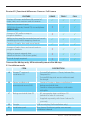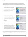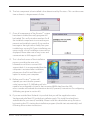
1
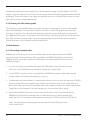
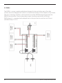
Version 5.0
Installation Guide
Congratulations on your purchase of Piscatus3D
Piscatus3D is a comprehensive 3-Dimensional fishing tool that displays in
superior detail, exactly what is happening underwater in real-time as
you fish. With an interface designed by fishermen for ease of use, view your
underwater fishing grounds as never before. Piscatus3D shows your boat,
the seabed, the target fish and your fishing gear. Built on a stable and
reliable technology platform, Piscatus3D automatically saves your data as
you fish. Piscatus3D is available in three customised applications designed
specifically for your fishing operations: Inshore Pro, Deep Sea Pro and
Piscatus3D Classic.
Piscatus Ltd is a wholly owned subsidiary of Seabed Mapping International
Ltd (SMI).
2
Piscatus3D Version 5 Installation Guide
Licence Terms
1.The Piscatus3D software (the Software), has not been designed as, nor purports to be,
a navigational aid and must not be used or relied upon as such by the user. The Software
is supplied solely as an aid to fishing not an aid to navigation.
The software is supplied on the express condition that Piscatus Ltd accepts no liability
for any loss of catch, failure to catch, loss of life, personal injury, or loss or damage to any
vessel or fishing gear resulting from the use of the software.
2. The licence entitles the user a single licence to use one copy of the Software installed
on a single terminal.
3. The sole entitlement of the user is as a licensee of the Software for the purposes
of the user only.
4. Piscatus Ltd retains sole and exclusive copyright of the Software and written material
supplied and neither the Software itself nor any written materials supplied with the
Software may be copied by the user, or made available to, or used by, any other person
in any manner.
5. All other rights are solely reserved to Piscatus Ltd.
6. Piscatus Ltd’s liability in respect of the Software is entirely limited to any
performance failure relating to the Software itself when operated strictly in accordance
with operator instructions. Piscatus Ltd’s liability is solely limited to a refund of the
purchase price of the Software. In particular no liability is accepted for any failure caused
by the operating environment in which the Software is installed or used;
any consequential loss or damage incurred by the user or any third party;
the consequences of any installation or reconfiguration of the user’s operating
environment by the distributor of the Software. All warranties implied by the law of any
jurisdiction are excluded to the maximum extent possible.
7. Piscatus Ltd accepts no liability whatsoever for any failure, breakdown or
incompatibility of any related hardware supplied by its distributors or dealers
or otherwise used to operate the software.
8. This licence continues until terminated. The user may terminate the licence by
destroying the CD containing the Software and all written material supplied or
returning it to the retailer/distributor from whom it was purchased. The licence
terminates automatically if the user is in breach of any provisions of this licence.
Piscatus3D Version 5 Installation Guide
3
9. If any provision in this licence is held to be unenforceable by any Court having
jurisdiction the rest of this licence will remain in full force and effect.
10. This licence is governed exclusively by the laws of New Zealand, and constitutes
the entire agreement between the user and Piscatus Ltd replacing the terms
of any purchase order, marketing material, communication, or any representation
by Piscatus Ltd or any distributor/retailer appointed by Piscatus Ltd.
ACCEPTANCE
The intending user of the Software has read the terms of this licence and by ticking the box
to install the Software accepts the above Licence Terms as exclusively constituting the terms
of use of the Software.
4
Piscatus3D Version 5 Installation Guide
1.0 INTRODUCTION......................................................................................................................7
1.1 What Is Piscatus3d...............................................................................................................................................7
1.2 Piscatus3d Modes.................................................................................................................................................7
1.3 How Piscatus3d Works....................................................................................................................................8
1.4 Built In Data............................................................................................................................................................10
1.5 Computer Specifications..........................................................................................................................10
2.0 INSTALLATION INFORMATION...........................................................................................12
2.1 INSTALLation types...........................................................................................................................................12
2.2 installation Media..........................................................................................................................................14
2.3 Installation Model........................................................................................................................................15
3.0 SOFTWARE INSTALLATION.................................................................................................16
3.1 INSTALLING Piscatus3D.....................................................................................................................................16
3.2 RUNNING Piscatus3d FOR THE FIRST TIME – OBTAINING THE PERMIT CODE..................19
4.0 CONFIGURATION OF SMISEALOG.....................................................................................21
4.1 INTRODUCTION........................................................................................................................................................21
4.2 COMM PORTS AND NMEA.................................................................................................................................24
4.1.1 Using SMISealog.......................................................................................................................................21
4.1.2 SMISealog quick setup............................................................................................................................22
4.1.3 Viewing SMISealog Status....................................................................................................................24
4.2.1 Viewing incoming data.........................................................................................................................24
4.2.2 Setting up comm ports..........................................................................................................................25
4.2.3 Listening to incoming data..................................................................................................................25
4.2.4 Sending data..............................................................................................................................................25
4.2.5 Using the automatic NMEA setup feature.....................................................................................26
4.2.6 Selecting NMEA settings........................................................................................................................26
4.2.7 NMEA examples.........................................................................................................................................27
4.2.8 Primary and Secondary depth data and auto-switch.............................................................28
4.2.9 Filtering data...............................................................................................................................................29
4.2.10 Enabling ‘Setup Mode’ to ignore GPS position problems......................................................30
4.2.11 Receiving ARPA target data................................................................................................................30
4.3 USING TIDE ADJUSTMENT..................................................................................................................................30
4.3.1 How tide adjustments are calculated..............................................................................................30
4.3.2 Viewing current tide adjustment........................................................................................................30
4.3.3 Selecting a tide engine (check)............................................................................................................31
4.3.4 Setting a default tide station to always be used..........................................................................31
4.3.5 Viewing a list of available tide stations in your area.................................................................31
4.3.6 Viewing the tide station graph............................................................................................................32
Piscatus3D Version 5 Installation Guide
5
4.4 SIMULATIONS..............................................................................................................................................................32
4.4.1 Recording simulation files.....................................................................................................................32
4.4.2 Playing recorded simulation files.......................................................................................................33
4.4.3 Simulation options...................................................................................................................................34
4.4.4 Playing preset simulations....................................................................................................................35
4.5 FAULT FINDING..........................................................................................................................................................35
4.5.1 Restoring factory defaults.....................................................................................................................35
4.5.2 Finding problems......................................................................................................................................35
5.0 USING MULTIPLEXERS.........................................................................................................37
5.1 MX4...................................................................................................................................................................................37
5.2 DM24...............................................................................................................................................................................37
5.3 HOW TO CONVERT FURUNO CIF TO NMEA0183 WITH A DM24.................................................39
6
Piscatus3D Version 5 Installation Guide
1.0 Introduction
1.1 What is Piscatus3D
Piscatus3D is a computer program that makes maps of the seafloor or lake bed for
commercial and recreational fishermen. It has been designed to help fishermen
catch more fish in less time. By connecting into a boat’s GPS, sounder and seafloor
discrimination device, a database can be built of the seabed’s depth, hardness and
roughness from the area the boat fishes. Depths are then used to build a model of the
seafloor and hardness and roughness characteristics are overlaid. By getting accurate maps
of the seafloor instantly, a fisherman can increase the boat’s efficiency markedly.
Seabed Mapping (Piscatus3D Ltd) is run by ex-commercial fishermen and it is a policy that
all our staff spend time at sea on commercial fishing boats. Our experience and close
association with the commercial fishing industry helps us to make our products as useful
as possible and easy to use for fishermen. We understand that fishermen want to catch fish
and not learn about computers.
Piscatus3D can interact with the boat’s plotter via a component called Shared Memory.
At the moment C-Plot Pro and SeaPlot Pro are supported. If a different plotter is used please
contact Seabed Mapping and we can see if we can integrate with it as well.
This manual details the background components of Piscatus3D, what they do and how they
all work together, the software installation procedure and the configurations necessary for
the Piscatus3D system to work with the boat’s electronic equipment. This manual assumes a
reasonable level of understanding of a PC, windows and marine electronics. Please consult
the Piscatus3D user manual for learning how to operate the software.
1.2 Piscatus3D modes
Piscatus3D is available in three different modes:
•
•
•
Inshore-Pro (commercial fishing)
Deepsea-Pro (commercial fishing)
Classic (recreational fishing)
This guide describes in principle the operation and functionality of all three modes but
the main focus is on the extended features of Inshore-Pro and Deepsea-Pro modes.
It is important to understand the differences between these modes and how the
modes overlap.
Piscatus3D Version 5 Installation Guide
7
Some functionality described in this guide does not apply to Piscatus3D Classic. Please visit
our website http://www.piscatus.co.nz/products.html#compare to compare all Piscatus
modes and their features.
Inshore-Pro produces the highest detail of the seafloor because of its finer data resolution
and depth accuracy. Deepsea-Pro is a more efficient system by storing less data it is able to
maintaining bigger map sizes in deeper waters. For most vessels Inshore-Pro is the current
choice, as it can give higher detail in shallow water but still stores data down to 3200 metres.
Deepsea-Pro is recommend for vessels working almost constantly over 1000 metres or
require 3D maps larger than 20 Nm.
Feature
Inshore-Pro
Deepsea-Pro
Data resolution
2.4 metres
20 metres
Depth accuracy
0.1 metres
1 metre
Minimum depth
0 metres
0 metres
Maximum depth
3200 metres
32000 metres
Minimum map size
1 Nm
5 Nm
Maximum map size
20 Nm
60 Nm
Best performance
< 1000 metres
> 1000 metres
< 1000 metres
High detail
Good detail
> 1000 metres
Small maps, detail same
as Deepsea-Pro
High detail, larger maps
1.3 How Piscatus3D works
There are five main software elements that make Piscatus3D work. These are:
•
SMISealog
•
Shared Memory
•
SeaDBLog
•Firebird Database Server
•
Piscatus3D
Figure 1 over the page shows one possible setup of a Piscatus3D system and the flow of data
between the various Piscatus3D elements. In this example, data is given out from the various
bits of electronic equipment on the boat in NMEA format. Each of these data outputs are
fed into a Data Multiplexer, which combines all the NMEA sentences into one data stream.
8
Piscatus3D Version 5 Installation Guide
This data stream is then fed into the Piscatus3D computer via a single comm port. This is a
common setup for vessels with more than two devices outputting data to Piscatus3D.
Other possible Piscatus3D setup options are to receive the data via UDP using the
computer’s ethernet port, or to send NMEA into multiple comm ports on the PC, thus
removing the need for a data multiplexer. UDP data is only available from some NMEA Data
Multiplexers or can be configured on another computer within the Piscatus3D computer’s
network. This setup allows multiple data sources to be shared over an Ethernet network to
multiple computers and multiple programs per computer. Setting Piscatus3D SMISealog to
listen to NMEA from many comm ports is a good option for users only requiring GPS and
echo sounder data, but correct precautions should be taken concerning electrical isolation
and device earthing. Please contact your Piscatus3D dealer concerning electrical isolation
and device earthing with your installation.
Piscatus
Figure 1: The relationships and data flow between Piscatus3D elements
SMISeaLog is a stand-alone program separate from Piscatus3D. SMISeaLog picks out the
various NMEA sentences it has been configured to recognize such as depth, position,
hardness and roughness, COG, SOG and net position, and writes these parametres to
Shared Memory. It also flags, or discards, errors in the incoming data such as an incorrect
position from the GPS, or the sounder coming off the bottom and giving erroneous depth
values. Piscatus3D and SeaDBLog then both read the values from Shared Memory. If C-Plot
Pro or SeaPlot Pro are also installed on the same computer, they can access Shared
Memory as well and use the parametres and values stored there. SMISealog also has a tide
calculation engine and calculates the tide based on GPS position and GPS date/time.
SMISealog then places this tide value in Shared Memory to be used by Piscatus3D and
SeaDBLog. Tide information comes from any of three tide engines, being the Piscatus3D,
TotalTide or Proudman tide engines.
SeaDBLog writes depth, hardness and roughness information from Shared Memory
to the Piscatus3D database file (C:\Piscatus3D\Data\BATHYMETRY.FDB). The SeaDBLog
program runs as a background Windows service called the ‘Sealog Database’. SeaDBLog
also creates trip logs, which are exported by the Map Manager program and can be
Piscatus3D Version 5 Installation Guide
9
imported into the Fleet Manager program. Fleet Manager is sold separately and is used
by commercial fisheries to maintain a central database back at head office.
Piscatus3D also reads Shared Memory to dynamically update the terrain model and boat
position in real time. Only when a new position is rendered does Piscatus3D fetch points
from the database.
Piscatus3D Inshore Pro and Piscatus3D DeepSea Pro both install from the same set of
disks. The Permit Code you are given by Seabed Mapping when licensing the software
determines what mode Piscatus3D will run in and whether any additional modules
are activated.
Navigator is another program that is opened from within Piscatus3D itself.
This program gives the user an overview of the world with coastlines, boat tracklines and
high resolution global bathymetry maps. Piscatus3D Navigator is standard with all Piscatus3D
Inshore Pro and Piscatus3D DeepSea Pro installations and does not require any extra
installation steps.
SmartNet™ is an add-on module that can be purchased in addition to the standard
Piscatus3D system. It is a net positioning system that determines net location by matching
depths received from the net sounder with seafloor depths stored in the Piscatus3D
database. SmartNet™ can be added on to any Piscatus3D DeepSea Pro installation.
If you are doing a SmartNet™ installation on a boat, please contact Seabed Mapping for
further details.
1.4 Built in data
Piscatus3D comes with a built in background dataset called Predicted Bathymetry
that covers the planet. This data is a one nautical mile grid cell dataset based on satellite
altimetry. The dataset is kept separate from the boat’s actual soundings and once the boat
has collected its own data the background data will be ignored where the owner’s data
is present.
Another type of background data is Piscatus3D relief data. These are high detail data files
available in some areas containing topographical and/or bathymetry data for localized
areas. This data is typically used to draw land terrain for inshore and lake fishing. The data
is installed separately from the Piscatus3D background Predicted Bathymetry and is only
available in areas where either topographical or bathymetry data is available in the public
domain. Typically the precision of this data is around 90m and therefore may produce some
10
Piscatus3D Version 5 Installation Guide
accuracy errors around the shorelines. Note however that boat data collected will always
override land data points present in same location.
In some special cases supplementary data can be supplied as text XYZ data and imported
into the user database via the Map Manager program. This data may come from a number
of different sources including other Piscatus3D users, hydrographical offices and government
agencies. Instructions for importing this type of data can be found in the user guidebook.
1.5 Computer specifications
The minimum system requirements for running Piscatus3D successfully are outlined below.
However, for performance reasons, we strongly suggest you obtain a system that
encompasses the recommended requirements.
Recommended system requirements:
•
Intel® Pentium® Dual Core Processor 1.8 GHz
•
1024 MB of DDR RAM
•
GeForce 6 series 256MB
•
nVidia Video Card essential
•
80GB 7200 RPM Serial ATA Hard Drive
Piscatus3D Version 5 Installation Guide
11
2.0 Installation information
The installation process of Piscatus3D can be undertaken in many different ways. This section
will explain some of the options and help to remove any uncertainties.
2.1 Installation types
1. Demo installation
2. Trial installation
3.Full installation
12
Piscatus3D Version 5 Installation Guide
ITEM
DESCRIPTION
1
Demo
Installation
• Installed by selecting the Demo Installation option
during installation
•Runs without a dongle or a permit code
• Will display pre-loaded bathymetry data
• Won’t record input from a sounder or GPS
• Can be installed on multiple computers
• Is a permanent installation
• Installs a database containing more pre-loaded data than
the trial or full versions
2
Trial
Installation
• Installed by selecting the Trial Installation option
during installation
• A 60-day trial license for the full version of Piscatus3D is
loaded during the installation process
• The trial version does not require a dongle although a permit code is required for the system to function
• Please note that once installed these 60-day trial licenses
cannot be un-installed or renewed
• The license will remain on the system for 60 days
• After 60 days the installation can continue to be used if
a dongle is purchased and inserted into the computer,
although you will need to contact us in sufficient time for us
to physically get a dongle to you
• The trial version has full Piscatus3D version 5 functionality i.e.
it can receive and save GPS and sounder data
3
Full Installation
• Installed by selecting the Full Installation option
during installation
• Is a permanent installation
• The installation requires a dongle to be present and also a
permit code supplied by SMI
• A trial version can be ‘upgraded’ to a full version within the
60 day trial, by purchasing a dongle and permit code from
SMI or your local dealer
Piscatus3D Version 5 Installation Guide
13
Piscatus3D | Functional differences: Demo vs. Full License
DEMO
TRIAL*
FULL
Displays 3D maps and allows full control of
maps, nets, cross sections and all cameras
FEATURE
P
P
P
Receives instrument inputs
(GPS, Echo Sounder, Simrad ITI) via multiplexer
(NMEA 0183)
O
P
P
Storage of 3D seafloor maps in
program database
O
P
P
Ability to play map files recorded on real vessels
simulating real world mapping situations
P
P
P
Creation of marks, lines and vessel tracks
P
P
P
Storage of marks, lines and vessel tracks in
program database
O
P
P
Ability to import external data
(details at Section 12.6 of user guide)
O
P
P
Physical dongle required
O
P
P
*Licensed for 60 days only. All functionality ceases after 60 days.
2.2 Installation media
ITEM
14
DESCRIPTION
A
Piscatus3D version 5
installation CD
•To install full options – Classic, Inshore-Pro,
Deepsea-Pro
•To install 60 day trial version without need
for dongle
B
Demo installation &
promotional movie DVD
•Contains Piscatus3D demo installation &
background relief data.
•Contains video presentations with audio
in English.
C
Background relief data CD
•3D topography data installation CD
(relevant to area of customer).
•Supplied separately with Item A above for
you only.
D
Dongle
USB security key (Full installation only)
E
Installation pack
Box, sleeve, Quickstart guide, user manual,
installation manual
Piscatus3D Version 5 Installation Guide
2.3 Installation model
Step 1:
Insert Disk
Insert Installation CD
Step 2:
Select Install
Type
Demo
Trial
Full
Step 3:
Confrim Installed
App
Demo
Trial
Full
Step 4:
Confirm License
Type
60 day
trial
Full with
dongle
Step 5:
Confirm Permit
Type
60 day
trial
Full
permit
Step 6:
Result
Demo
mode
Trial
mode
Full
mode
Step 7:
Optional
N/A
Purchase*
Full
mode
*Purchase of full mode requires both a dongle and permit code supplied by SMI.
Piscatus3D Version 5 Installation Guide
15
3.0 Software Installation
3.1 Installing Piscatus3D
Note – make sure your logon rights have Administrator permissions before you start.
1.
Place the Piscatus3D installation CD in the computer’s CD drive. The setup program should start automatically, however if Autorun is disabled on the machine you will have to start it manually. To do this go to Windows Explorer and navigate to the CD drive and double click on the ‘SetupPiscatus5.exe’.
2.
The Piscatus3D installation window will open, as shown to the right. This is an introduction to the installation process giving a description and overview.
By default the graphics test will auto
matically start when the ‘Next>’ button is pressed, but this graphics test can be skipped by unselecting the checkbox ‘Perform graphics test’.
3.The graphics test is the next element of the
installation program to be displayed (unless
skipped from the previous installation
welcome page). The graphics test will load
and start automatically. Once the graphics
test is completed the result window to the
right will be displayed. Please take note of
both the FPS result and result description.
Press the ‘Continue’ button to continue the
installation program.
4.This stage of the installation process allows
the user to select the type of installation
required. Please be sure which installation
type you need. If you are unsure, previous
sections of this Installation Guide have
information about the installation types.
To continue you must select an installation
type and press the ‘Next>’ button.
16
Piscatus3D Version 5 Installation Guide
Note: Trial installations can be converted to full installations by purchasing a dongle
and requesting a new full version permit code. But please be aware that the trial will not
run once the 60-days has expired and that there may be some downtime before a dongle
is received.
5.This stage of the installation process seeks
to confirm the users understanding of
the installation type they have selected.
Please read the installation type description
carefully and follow its instructions to
continue the installation.
6.This stage of the installation process is
only displayed if an existing installation of
Piscatus3D is found on the computer.
By default all options shown are not replaced,
but the user may check any of the options
they wish to replace. Once the user is happy
with their selections press the ‘Next>’ button
to continue.
7.This is the final stage of the installation
process. By default all options should be
checked, but users may wish to only install
sections of the program when repairing
previous installations. Once the user is happy
with their selections press the ‘Next>’ button
to continue. The program will now install the
components you have selected.
Note: For FleetManager installations please manually select the ‘Install FleetManager’ option.
Anyone can install FleetManager but it will only run if a FleetManager license is obtained
from SMI or your local dealer.
Piscatus3D Version 5 Installation Guide
17
8.The first component of the Piscatus3D system to be installed is the HASP SRM RTE which
manages the licensing of Piscatus3D. This must be installed first as components installed
later in this process require it. Please note that Anti-virus scanners must be disabled
during the installed of this component, as displayed on the message box below.
During installation of the HASP SRM RTE the following will be displayed
Once the HASP SRM RTE has been installed you will be prompted to insert your Piscatus3D dongle. The installation system will automatically detect the dongle once inserted and proceed to the next section of the installation.
9.The next component to be installed is Piscatus3D itself, followed by the Firebird
database server.
18
Piscatus3D Version 5 Installation Guide
10.The last component to be installed is the dataset used by Piscatus3D. This can take some
time as there is a large amount of data.
11.Once all components of the Piscatus3D system
have been installed the verify program will
be loaded. This verify window searches for all
the installed components to ensure they are
present and installed correctly. If you see the
message to the right with a smiley face your
installed was successful. If your installation was
unsuccessful a list of installation issues will be
displayed. Please take note of any issues and
communicate to SMI support staff.
12.This is the final screen of the installation
process providing the user with
information on how to contact SMI
support desk. It is recommended that the
computer is restarted after installation,
please press the ‘Exit and Reboot PC’
option to restart your computer.
13.
Before your Piscatus3D system will
operate you must obtain a permit code (see section 3.2). SMISealog will also need to be configured to listen to the incoming NMEA data from the GPS,
echo sounder and seabed discrimination device (if present). Instructions for configuring
SMISealog are given in section 4.0.
14.
If you are outside New Zealand it is possible that you will be supplied an extra ‘background relief data’ CD inside the installation pack. This installs land and basic seabed data for your area (if available). Please install this data before using Piscatus3D by inserting the CD, starting the installation program (should start automatically) and following the onscreen instructions.
Piscatus3D Version 5 Installation Guide
19
3.2 Running Piscatus3D for the first time – obtaining the Permit Code
Piscatus3D uses a dongle and a special code (referred to as a Permit Code) for its security and
licensing. If your local supplier does not have a dongle in stock a 60-day trial can be installed
and used without a dongle. This gives you a window of time to organise the delivery of
a dongle, so that your Piscatus3D system can be permanently used. Please give you local
supplier as much notice as possible to avoid purchasing a Piscatus3D system when no
dongles are being held in stock.
To obtain the Permit Code to licence Piscatus3D and operate the software you need to
contact Seabed Mapping and provide us with the Computer ID of the machine you are
installing Piscatus3D on.
1.The first time you run Piscatus3D after installation the ‘Computer Identity’ window will
open, as shown below.
2.Please supply Piscatus3D Limited with the 32 digit Computer Identity code either
via email ([email protected]), or through our website dealer login page
(http://www.piscatus.co.nz/login.htm). If you do not have internet access you can phone
us on +64 3 545 7020 or fax the code to +64 3 545 7021. We strongly recommend using
either email or the internet and copying and pasting the codes so as to prevent any
potential errors when copying them down.
Other Information we require is the Piscatus3D mode (either Inshore Pro or DeepSea Pro),
vessel name, and the company name the vessel belongs to. The latter is only used when
generating the Permit Code as Piscatus3D installations have encryption routines that take
into account the parent company to allow data sharing between vessels using the Fleet
Manager and Map Manager programs.
20
Piscatus3D Version 5 Installation Guide
3.SMI will reply with a 66 digit Permit Code that should be entered in the bottom text
field of the above ‘Computer Identity’ window. Once the Permit Code has been entered,
click the ‘Accept’ button to continue. Piscatus3D will automatically load after you have
accepted the Licence Terms.
4.Piscatus3D is now ready to use. Click the ‘Follow Boat’ option in the upper left hand
corner of the screen and you will be taken to the current boat GPS position.
Note: SMISealog may need to be configured before Piscatus3D can receive GPS position
and other data – see section 4.0.
4.0 Configuration of SMISealog
After Piscatus3D has successfully installed you will need to configure it correctly so that
it talks to the boat’s electronic equipment. Most of the required configurations are default
settings but they may need a little tweaking depending on the boat involved.
4.1 Introduction
SMISealog is the data entry point for the Piscatus3D system. SMISealog listens to the data
being sent into the PCs serial comm port or UDP network. This data is received in NMEA
format from marine equipment, for example, GPS or echo sounder. SMISealog then extracts
the required data from this and shares it to Piscatus3D to be viewed.
SMISealog also uses GPS position, date and time data to calculate the current tide
at boat position. This tide value is used by Piscatus3D to correct all recorded depth data
to chart datum.
When you first install Piscatus3D there are some settings in SMISealog that will need to
be set. Please read the ‘SMISealog quick setup’ section (4.1.2) of the manual for a brief
description of this setup stage, or read the remainder of the manual for a detailed
step-by-step description.
4.1.1 Using SMISealog
SMISealog runs as a background task to Piscatus3D and runs in
the Windows system tray. To access the SMISealog menu left
click on the small white and red fish icon. From this menu you
can do simple tasks like starting and stopping tide adjustment,
viewing the current tide graph or opening the ‘SMISealog
Control Panel’ window. A picture of the SMISealog menu is
shown on the left.
Piscatus3D Version 5 Installation Guide
21
The top option called ‘Control Panel’ opens the ‘SMISealog Control Panel’ window where
SMISealog settings are set and modified, as shown below:
The SMISealog control panel is designed using tab controls. There are two main tabs along
the top for NMEA processing and tide adjustment. Beneath each of these main tabs are
sub tabs that group different options available to the user. The status bar along the bottom
shows which comm ports are currently being used.
4.1.2 SMISealog quick setup
1.Turn on all electrical equipment that has been wired to send data to Piscatus3D.
This includes equipment like GPS, echo sounder and data multiplexer. Check data
cables are correctly plugged into PC serial rs232 comm ports.
2.Check for data in terminal. Open the ‘SMISealog Control Panel’ window by left clicking
on the SMISealog icon and selecting the ‘Control Panel’ option. In the window that
opens, click the ‘NMEA Processing’ tab and then the ‘Terminal’ tab. Select different comm
ports from the ‘Display Input’ list. Data will appear as white lines of text against the black
background, each line will normally start with the $ character. Note down a list of which
comm ports display data.
Example data string:
$GPGGA,212812,4107.138,S,17423.858,E,1,7,2.1,-1,M,19,M,,
22
Piscatus3D Version 5 Installation Guide
3.In the ‘SMISealog Control Panel’ window, click on the ‘NMEA Processing’ tab and then
the ‘Comms’ tab. In the ‘Read input from (Max 5 ports) list, tick each of the comm. ports
for the appropriate input comm port as noted in Step 2. Finally tick the ‘Enable Comms’
option to start data processing.
4.The quickest way to set up your NMEA processing options is to open the ‘SMISealog
Control Panel’ window, click on the “NMEA Processing’ tab and then the ‘System’ tab,
and in here click the ‘Auto Detect NMEA Settings’ button. This process will monitor all
incoming data for thirty seconds then automatically select the best options. In the
‘Net NMEA’ tab you should select the type of net monitoring equipment (if any) used.
5.Now check the incoming data. In the ‘SMISealog Control Panel’ window, click the
‘NMEA Processing’ tab and then the ‘Comms’ tab, and then click the ‘Display incoming
data’ button. This will open the ‘Incoming data’ window. Check the different fields in
this window, there needs to be a minimum of the following items in order for Piscatus3D
to operate:
•UTC Date
•UTC Time
•
Latitude
•
Longitude
•
Depth
6.If some fields are missing like Heading or SOG, go to the ‘Boat NMEA’ tab and select
the appropriate NMEA sentence type. Heading may need to be changed from GPHDT
to RMC. Heading, COG and SOG data is not essential but does make the software
better to use.
7.Once you have selected a tide engine, if a tide station is available in your area the above
data will be enough to calculate its current height. Allow up to 30 seconds for the tide
engine to find a station after a lat long position is detected by SMISealog. Additional tide
station options can be chosen on the ‘Tide Adjustment’ tab in the ‘SMISealog Control
Panel’ window.
8.If you have net sensors attached to your trawl this data should appear in the ‘Incoming
data’ window in the right hand column called ‘Data From Net’. Most trawl sensor systems
need to be in a simulation mode in order to output data when the net is not in
the water.
Piscatus3D Version 5 Installation Guide
23
Note - if you are missing important data you may have to customize your NMEA or filtering
settings. Please check ‘Selecting NMEA settings’ and ‘Filtering Data’ sections of this manual for
further assistance.
9.Start Piscatus3D. If all required data is shown in the ‘Incoming data’ window,
start Piscatus3D. Piscatus3D should detect the data and load a 3D seabed for around
the boats current position, when this happens the ‘Follow boat’ option in the bottom
left of Piscatus3D will be ticked.
4.1.3 Viewing SMISealog Status
The ‘System’ first tab under the ‘NMEA Processing’ tab of the ‘SMISealog Control Panel’
window gives you a quick summary of SMISealog’s current status.
The top section called ‘Current Status’ gives you a live update of the most important data
values being used by Piscatus3D. All these data values and the data status readings are
important for Piscatus3D to work correctly. Also displayed here is the status of database
logging and trip logging.
The bottom section called ‘Setup Tools’ gives you an option to open a virtual keyboard for
users of Piscatus3D with touch screen displays. This virtual keyboard can be used anywhere
in Windows to enter text. A user can also restore factory settings and perform an automatic
NMEA setup.
4.2 Comm ports and NMEA
4.2.1 Viewing incoming data
To view the incoming data, open the ‘SMISealog Control Panel’ window, click the “NMEA
Processing’ tab and then ‘Terminal’ tab. The control on the left called ‘Display Input’ is where
you select the comm port you wish to view data coming in from. The control to the right
is a where the associated incoming data is displayed - this control is black and will display
lines of incoming NMEA data with white text. Sometimes these lines of data will appear very
quickly and must be paused in order to be read. To pause the incoming data click the ‘Pause’
button at the bottom of the window.
For example, to view data coming in from comm port 3:
Left click on the ‘Comm3’ option in the ‘Display Input’ list. When this option
has been checked data from comm port 3 will be displayed on the right hand black
data display area.
24
Piscatus3D Version 5 Installation Guide
4.2.2 Setting up comm ports
To set SMISealog to listen for incoming data, open the ‘SMISealog Control Panel’ window
and click the ‘NMEA Processing’ tab and then the Comms tab. Comm ports can set up to
listen for, or to send data. From the ‘Comms’ tab the baud rate (speed) of data being sent
or received can be set and whether or not incoming data should be checksum validated.
There are also options to completely stop/start data comms and database logging.
Note - data cannot be read and sent from the same comm port. In order to read and send data
you must have a minimum of two available comm ports.
Setting the correct comm port and NMEA settings can be complicated and should only
be done by a marine electronics technician.
4.2.3 Listening to incoming data
To listen to incoming data from a specific comm port, open the ‘SMISealog Control Panel’
window. Click the ‘NMEA Processing’ tab and then the ‘Comms’ tab and click on the required
comm ports name from the list on the left entitled ‘read input from (Max 5 ports)’. A tick will
appear to the left of the comm port’s name to indicate that SMISealog is listening to this
comm port for data. Up to five comm ports can be selected to receive data.
4.2.4 Sending data
Data can be sent from SMISealog out a comm port. For example you can send data to a
CNBX that is using the SmartNet system; send data to another PC or device; or send data to
another comm port for another application.
To send data from a specific comm port, open the ‘SMISealog Control Panel’ window.
Click the ‘NMEA Processing’ tab and then the ‘Comms’ tab and click on the required comm
ports name from the list on the right entitled ‘Send output to (Max 2 ports)’. A tick will
appear to the left of the comm port’s name to indicate that SMISealog is sending data out
this comm port. Up to two comm ports can be selected to send data.
Piscatus3D Version 5 Installation Guide
25
4.2.5 Using the automatic NMEA setup feature
The automatic NMEA setup feature is designed to listen to the data being received by
SMISealog and automatically set all NMEA string settings. It does this by listening to the
receiving data for a set time and using the highest count values of received NMEA strings to
select the best settings. To access this automatic NMEA setup feature, open the ‘SMISealog
Control Panel’ window, click the ‘NMEA Processing’ tab and then the ‘System’ tab, and then
click the ‘Auto detect NMEA Settings’ button. Before starting the automatic NMEA setup
feature make sure all marine electronic devices sending data to Piscatus3D are switched
ON and sending data. Please refer to the ‘Viewing incoming data’ section of this manual
for information on viewing incoming data.
4.2.6 Selecting NMEA settings
All data sent to Piscatus3D must be in NMEA format. This format sends lines of data with
each line containing an identifier and data delimited by commas. There are many different
NMEA strings, some of which contain the same data. Piscatus3D must be set up to process
the NMEA data your equipment is sending. Piscatus3D knows how to process many different
NMEA strings, but needs to know which ones to expect. This means setting the identifier
Piscatus3D will listen for depending on the data type required. An identifier is made up of
two parts - a talker and a data type.
For example, depth data has a talker of SD and data type of DBS, therefore the identifier
is SDDBS.
Setting the correct comm port and NMEA settings can be complicated and should only be
done by a marine electronics technician.
Roughness and hardness NMEA setup is much easier. Simply choose between JRC echo
sounder, or SeaScan or RoxAnn seafloor discrimination systems. There are offset values that
can be entered for this data. We have found that different echo sounders and SeaScan units
give out different values for the same type of seafloor. This offset value allows you to correct
these differences between units when data sharing between vessels.
The ‘Net NMEA’ tab has options for setting up Piscatus3D to listen to your net positioning
equipment. With these data, Piscatus3D can put your net in a real position relative to the
terrain, for more effective fishing. There are options to select what type of net positioning
system you have. Selecting one of these will set the correct NMEA setting below. Settings
may need to be adjusted for each installation.
26
Piscatus3D Version 5 Installation Guide
The default settings in Piscatus3D should be correct to get GPS position and echo sounder
depth from most modern marine electronic equipment. The best way to find what NMEA
strings your equipment outputs in to use the terminal tab in SMISealog. Use this to view a
comm ports data and press the pause button to stop the data display update so you can
read to the individual NMEA strings being received.
If you are having problems setting up SMISealog to listen to your NMEA strings, please try
the ‘Automatic NMEA setup’ feature. For information on this please refer to section 3.2.5.
4.2.7 NMEA examples
Position, heading and speed
GPS
$GPGGA
GPS position and time
$GPRMC
GPS position and time
$GPVTG
Speed and course over ground
$GPZDA
Time and date
Gyro
$GPHDT
Vessel heading
Depth
Sounder
$SDDBT
Depth below transducer
$SDDBS
Depth below sounder
There is an option on the ‘BOAT NMEA’ tab to enable support for an old JRC NMEA format
with a leading ‘U’ character.
Hardness/Roughness data
JRC JFC130
$PJRCSHardness data
SeaScan
$PSAP
Depth, Hardness and Roughness data
RoxAnn
N/A
Depth, Hardness and Roughness data
Piscatus3D Version 5 Installation Guide
27
Net information
When using any of the following please ensure that the correct net monitor is selected on
the ‘Piscatus3D Setup’ window.
Simrad ITI
$IIGLL
Net position
$IIDBS
Depth below sounder
$IIHFB
Trawl height footrope and bottom
$IITDS
Trawl spread
Furuno CN22
$IIDBS
Depth below sounder
$IIMTW
Temperature
Scanmar
$SMDBS
Depth below sounder
$SMHFB
Trawl height footrope and bottom
$SMTDS
Trawl spread
Netview3D
$IIN3D
Net position, depth, range, height and temperature
Pacha Geonet
$IISAL
Net sensors range, bearing and depth
$IISAN
Net sensors height, temperature and spread
4.2.8 Primary and Secondary depth data and auto-switch
Some vessels have more than one echo sounder. One could be a backup or preferred at
increased depths. The ‘Sounder Data’ section of the ‘Boat NMEA’ tab allows SMISealog to be
setup to receive data from two different NMEA strings. SMISealog will switch from primary
to secondary (or vice versa) automatically when no depth data has been received for some
time or when the auto-switch depth is crossed.
28
Piscatus3D Version 5 Installation Guide
4.2.9 Filtering data
To access the filter settings, open the ‘SMISealog Control Panel’ window, click the ‘NMEA
Processing’ tab and then the ‘Filtering’ tab. The Piscatus3D system does data cleaning and
these are the filtering settings here in SMISealog. These settings allow incoming data points
to be compared with recent data points and are designed to filter out erroneous data
points, for example, double echo used as bottom depth by your echo sounder.
Filter setting
Description
Vessel position
Sometimes GPS position can jump and cause Piscatus3D to load
another 3D seabed map. By setting this option GPS positions
further than 1000 metres from your last known good position will
be ignored. This is automatically corrected if more than six GPS
positions are found to be beyond 1000 metres.
Min/max
acceptable depth
This is a simple check on the data coming in from the echo
sounder. It basically stops huge errors from the echo sounder and
also keeps data within the limits of the Piscatus3D 3D system.
Echo sounder
Depths
This filter compares incoming data with recent data points and
is designed to filter out erroneous data points, such as a double
echo. It generates an average for the last x points and allows for an
error of y, if the new data is outside the range of y for z readings,
the average is reset using new data. The default settings for this are
X = 5, Y = 50 and Z = 10.
Depth offset
This setting allows you to set how far under the water line your
transducer is. When a depth is received from your echo sounder
this distance is added.
Net height
This filter works in the same way as the above filter but on the
net height from seabed data. X = 3, Y = 10 and Z = 5.
Net depth
This filter works in the same way as the above filter but on the
net depth below sea level. X = 3, Y = 20 and Z = 5.
Cleaning level
When each point is added to the database it is compared
against points around it. By default this is on the normal setting.
If you struggle with bad data from your echo sounder try the
high setting. Database cleaning can also be stopped by setting the
cleaning level to none.
Piscatus3D Version 5 Installation Guide
29
4.2.10 Enabling ‘Setup Mode’ to ignore GPS position problems
SMISealog is normally configured with the vessel at the wharf/Dock. As the vessel is not
moving SMISealog will flag the data as having a problem, therefore causing Piscatus3D
to ignore all data. There is a setup mode option at the bottom on the ‘System’ tab in the
SMISealog control panel. Place a tick in this option to make SMISealog ignore GPS position
problems so data can be checked in Piscatus3D. This option is not saved and will be
un-ticked when SMISealog is next loaded.
4.2.11 Receiving ARPA target data
The settings for receiving ARPA target data are on the ‘boat NMEA 2’ tab in the SMISealog.
SMISealog is only able to receive data from the radar NMEA string $RATTM. If this string is
being received that ARPA targets within that string will be listed on this tab. There are no
other settings which need to be adjusted.
4.3 Using tide adjustment
4.3.1 How tide adjustments are calculated
Piscatus3D is a utility built into SMISealog that uses data from tide stations around the world
to calculate the tide. Corrections can then be applied to depth data stored in the Piscatus3D
database. The tide station used to calculate the current tide is the closest station within
range of the boat’s position. This range is 40,000m (40km) by default, but it can be changed.
Once the tide station is found, the GPS date/time (or, if unavailable, your computer’s date/
time) is used to calculate the tide.
4.3.2 Viewing current tide adjustment
To view the current tide at the boat’s position, open the ‘SMISealog Control Panel’ window,
click the ‘Tide Adjustment’ tab and then the ‘Current Tide’ tab. This tab displays the data used
to generate the tide value, and when it was last updated.
30
Piscatus3D Version 5 Installation Guide
4.3.3 Selecting a tide engine (check)
SMISealog is able to calculate tide with three different engines. The first is the Piscatus3D
Tide Engine and is available worldwide with every installation of Piscatus3D.
There are another two tide engines available which are able to produce better tide
calculations in European countries; these are TotalTide and Proudman. Both these tide
engines must be purchased and installed separately before they can be used in SMISealog.
Please contact your local Piscatus3D dealer for details on obtaining a copy of these
tide engines.
The TotalTide tide engine requires no extra settings to be selected before it begins
to provide tide values to Piscatus3D. But the Proudman tide engine requires you to select
the data and license files, which are in the Proudman installation directory.
4.3.4 Setting a default tide station to always be used
This feature is only available when using the Piscatus3D tide engine. By default SMISealog
automatically uses the closest tide station in order to calculate the current tide value.
The user can override this setting by manually selecting a default tide station.
1.Open the ‘SMISealog Control Panel’ window and click on the ‘Tide Adjustment’ tab
and then the ‘Current Tide’ tab.
2.In the ‘Tide Options’ section at the bottom of the window, click the ‘Always use’ option,
then click the ‘Set’ button.
3.A message will pop up asking you to select the tide station to use, dismiss
this message by clicking the ‘OK’ button. You will automatically be taken to the
‘Lookup’ tab of Piscatus3D Tide.
4.Click the ‘Set as default station’ button.
5.You will be returned to the ‘Current Tide’ tab and you will notice that the tide station
you just selected is now displayed in the ‘Always use’ box.
4.3.5 Viewing a list of available tide stations in your area
This feature is only available when using the Piscatus3D tide engine. To view a list of available
tide stations in your area, open the ‘SMISealog Control Panel’ window and click on the
‘Tide Adjustment’ tab and then the ‘Lookup’ tab. Enter a latitude and longitude for your
area and click the ‘Lookup’ button. The tide engine will search for tide stations around the
Piscatus3D Version 5 Installation Guide
31
latitude/longitude position entered up to the maximum range set (the default is 40,000
metres). The tide stations found to be within range of the latitude/longitude entered will be
displayed. These tide stations can then be selected and set as a default tide station or their
tide values can be viewed graphically.
4.3.6 Viewing the tide station graph
This feature is only available when using the Piscatus3D tide engine. To view a tide graph
open the ‘SMISealog Control Panel’ window and click on the ‘Tide Adjustment’ tab and
then the ‘Graph’ tab. This tab will automatically show the current tide station being used
but different tide stations in the area can be viewed by selecting them from the drop down
box. Tide stations for other areas can also be displayed by searching for them using the
lookup feature on the ‘Lookup’ tab described above.
4.4 Simulations
4.4.1 Recording simulation files
SMISealog can be set up to record simulation files in the ‘System’ tab of the ‘NMEA
processing’ tab. These simulation files record the raw NMEA data being received by
SMISealog and using the simulator in SMISealog can be played back and sent into
SMISealog again.
1.To start recording a simulation file open the ‘SMISealog Control Panel’ window,
and click on the ‘NMEA Processing’ tab and then the ‘System’ tab.
2.In the ‘NMEA Log Files’ section, tick the ‘Record NMEA log’ option. Optionally specify
a date when you wish the recording to cease at.
3.Underneath this option there is a setting that allows you to control the amount of NMEA
data recorded. We recommend ‘Every line’ be used. However, for users with little hard
drive space the recording of simulation files over a week or more can create some rather
large files so this frequency can be changed to conserve hard drive space.
4.Recorded simulation files are stored on the hard drive in the C:\Piscatus3D\Data\
NMEAlogs\ folder Each simulation file is named based on its date created with
extension ‘.txt’. For example, a file created on August 31 2005 would be 31082005.txt
Note - for information on playing back a recorded simulation file please refer
to the section 4.4.2.
32
Piscatus3D Version 5 Installation Guide
4.4.2 Playing recorded simulation files
In order to play a recorded simulation file, NMEA settings must be correctly set. This section
of the manual only covers use of the simulation and not SMISealog setup.
1.To start a simulation open the ‘SMISealog Control Panel’ window and click on the ‘NMEA
Processing’ tab and then the ‘Simulation’ tab.
2.Click the ‘…’ button. This will open an ‘Open’ file dialog box, use this to navigate to, and
select, a NMEA simulation file.
3.Set the ‘Play Options’. The play speed of the simulation can be adjusted by changing
the Line delay (m/s). We recommend 100 m/s. Increasing the line delay will slow
the simulation.
4.Click the ‘Start SIM’ button to start the simulation.
5.Check the simulation progress. The simulation progress can be checked in two places.
The first is the progress bar below the ‘Start SIM’ button; this should be slowly filling as
the simulation file is played. Below the progress bar there is also a line count that should
be increasing.
6.It is important to check the ‘Terminal’ tab to make sure that simulation data is entering
SMISealog. To do this click on the ‘Terminal’ tab and click the ‘Display SIM data’ button.
White lines of text should be appearing against the black background.
7.Check processed data. Now check that all data is being processed correctly. To do this
select the ‘Comms’ tab and click the ‘Display Incoming data’. The ‘Incoming Data’ window
will now be displayed showing you which data is being received and processed.
8.Start Piscatus3D if all the above steps have worked correctly. You will be able to watch
the simulation play.
Piscatus3D Version 5 Installation Guide
33
4.4.3 Simulation options
There are many specialized options, which can be fine tuned in the simulator.
Below is a table of these options which a description on how to use them.
Option
Description
Line delay
This option controls the speed of the simulation. Simulation files
are made up of NMEA lines of data, increasing the delay between
sending each line of data slows the simulation. Default = 100 m/s
File Repeat
By default this is set to play once. This means that the simulation
will play from start to finish only once and then stop. There are two
further options for playing twice and forever.
Start or continue
options
These options allow the flow of the simulation file to be changed.
There are three options.
•From start
•From line
•
Continue
From start - starts the simulation from the start every time
the ‘Start SIM’ button is clicked.
From Line - allows the user to set the start point in the simulation
file based on its line number. The simulation will start from this
point each time the ‘Start SIM’ button is clicked.
Continue - allows the user to stop the simulation and continue
from where it stopped. The simulation will start from where it was
stopped when the ‘Start SIM’ button is clicked.
Simulation
output options
These options allow the user to control the processing and output
of data. There are three options that are self-descriptive. They are
used for simulations where data is being sent to another computer,
device or comm port. Default = ‘Process and don’t send NMEA to
output (comm port)’.
Simulation comm
output options
These options allow the user to control the flow of data being
sent out comm ports. These are used for simulations where data
is being sent to another computer, device or comm port.
Default = Out GP and SD to same port.
34
Piscatus3D Version 5 Installation Guide
4.4.4 Playing preset simulations
SMISealog is installed with three built in simulations. These are useful for Piscatus3D
dealers for show room presentations and other situations where the system must be
viewed in operation but no real data is available.
Preset simulations are available through the ‘SMISealog Control Panel’ window under the
‘NMEA Processing’ and ‘Preset SIMs’ tab. Simulations are started by selecting one of the three
simulation buttons and stopped by pressing the ‘Stop SIM’ button. As when playing
simulation files the speed of the simulation can be changed by reducing or increasing
the line delay.
4.5 Fault Finding
4.5.1 Restoring factory defaults
If SMISealog settings have been modified and SMISealog will not work correctly, restoring
factory settings may help. This will restore comm port, NMEA, filtering and tide settings.
Once factory defaults have been restored all settings would have to be adjusted to the users
setup again.
1.To restore factory defaults, open the ‘SMISealog Control Panel’ window, click on the
‘NMEA Processing’ tab and then the ‘System’ tab.
2.In here, click the ‘Restore Factory Defaults’ button.
4.5.2 Finding problems
If Piscatus3D does not seem to be working correctly please check all of the following.
These checks are written at a marine technician level and do not give every detail
on fixing the problem.
Check services
In the bottom left of Piscatus3D there are six lights. All six lights should be green for
Piscatus3D to be working correctly. If one or more light is not green place or mouse over
the light and you will get a short message of the problem. SeaDBLog can be restarted
in Piscatus3D through the Help | Support | System Information window. In the ‘System
Information’ window that opens, click the ‘Database’ tab and in here you will see buttons
called ‘Stop SeaDBLog Service’ and ‘Start SeaDBLog Service’. SMISealog has to be manually
restarted via the Windows Start Menu. Firebird must be started through Windows Services
in the Administrative Tools section of Control Panel.
Piscatus3D Version 5 Installation Guide
35
Check data being received and processed
If the bottom right light in Piscatus3D is flashing or solid red check SMISealog is receiving
and processing the data correctly through the ‘Terminal’ or ‘Comms’ tab of the ‘SMISealog
Control Panel’ window. When viewing incoming data check for position and depth data
and data lags being issued.
Check Shared Memory in Piscatus3D
If data is being correctly received and processed in SMISealog check that
Piscatus3D is receiving this data. To do this, go to the Help menu and select
Support | System Information. Click on the ‘Shared Memory’ tab and click the
‘Auto update’ option so it is checked. The values being sent to Piscatus3D from
SMISealog will be displayed. Check these values against the incoming data
in SMISealog to make sure they are the same.
36
Piscatus3D Version 5 Installation Guide
5.0 Using multiplexers
Multiplexers are used to merge incoming data from multiple sources into one data stream.
We recommend the MX4 and DM24 data multiplexers available from Pacific Micro Systems
(http://www.pacmicro.com/products.html)
5.1 MX4
The MX4 is a simple multiplexer designed to be used when up to four data sources are
to be merged, each source is in NMEA0183 format and up to four NMEA0183 outputs are
required. This unit is wired up as follows with each data source and destination being wired
into the top of the unit. Each source is wired to pins 2(+) and 7(-). Each destination is wired
to pins 1(ground) and 3(+).
Piscatus3D Version 5 Installation Guide
37
5.2 DM24
The DM24 is a more complex multiplexer designed to be used when up to four data
sources are to be merged, each source is in any format and up to four outputs in any format.
The unit is wired up as follows, with each device and the DM24 being plugged into the
DM22/4 Junction Box. The incoming data comes into the junction box, out to the
DM24 where it is converted and merged, back to the junction box and out an I/O port
(standard setup = I/O 1).
38
Piscatus3D Version 5 Installation Guide
5.3 How to convert Furuno CIF to NMEA0183 with a DM24
The conversion of formats is done in the DM24 using two dip switches. In the following text
switch states are described as 0 or 1, where 0 represents off and 1 on.
The first thing to do is to plug the devices into the DM22/4 Junction Box. The important
thing here is to plug the Furuno CIF signal into I/O 2, which is the same position as Device 2
in the diagram at the start of this section.
Now you must set the dip switches in order to convert the signal format. First take the top
of the DM24 unit. There are four switches on dip switch 2, set them all to 1. There are eight
switches on dip switch 1 from 1 to 8 set each switch as follows; 00100000. Turn the DM24 off
and on to save the new settings.
To test the DM24 conversion turn on only the attached Furuno CIF device and watch the
SMISealog ‘Terminal’ window to ensure the correct format data is being received.
Piscatus3D Version 5 Installation Guide
39