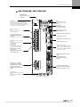
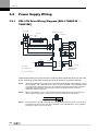
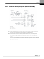
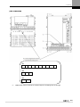
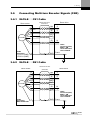
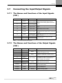
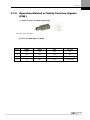
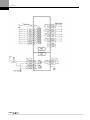
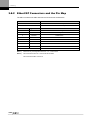
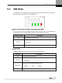
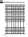
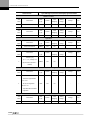
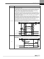
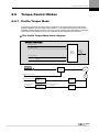
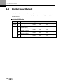
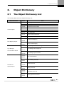
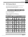
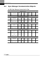
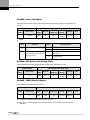
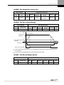
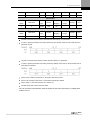
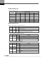
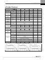
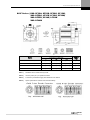
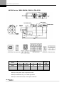
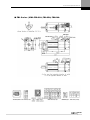
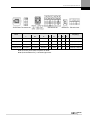
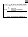
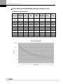
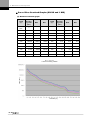
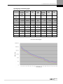
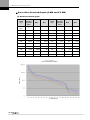
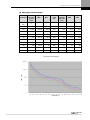
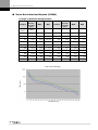
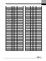
1
Introduction XDL-L7N Series User Manual i Introduction Introduction Hello. Thank you for choosing the LSIS XDL-L7N Series AC Servo. This user manual describes how to use this product safely and efficiently. Failure to comply with the guidelines outlined in this manual may cause personal injury or damage to the product. Be sure to read this manual carefully before using this product and follow all guidelines contained therein. The contents of this manual are subject to change without notice. The reproduction of part or all of the contents of this manual in any form, by any means or for any purpose is strictly prohibited without the explicit written consent of LSIS. LSIS retains all patents, trademarks, copyrights and other intellectual property rights to the material in this manual. The information contained in this manual is only intended for use with LSIS products. EtherCAT® is registered trademark and patented technology, licensed by Beckhoff Automation, Gmbh, Germany. ii Safety Precautions Safety Precautions Safety precautions are categorized as either Warnings or Cautions, depending on the severity of the precaution. Precautions Warnings Caution Definition Failure to comply with these guidelines may cause serious injury or death. Failure to comply with these guidelines may cause personal injury or property damage. Precautions listed as Cautions may also result in serious injury. Electric Safety Precautions Warning Before wiring or inspecting the device, turn off the power, wait 15 minutes, ensure that the charge lamp is off, and then check the voltage. Ground both the servo drive and the servo motor. Only specially trained technicians may perform wiring on this product. Install both the servo drive and servo motor before performing any wiring. Do not operate the device with wet hands. Do not open the servo drive cover during operation. Do not operate the device with the servo drive cover removed. Even if the power is off, do not remove the servo drive cover. Fire Safety Precautions Caution Install the servo drive, the servo motor, and the regenerative resistor on non-combustible materials. Disconnect the input power if the servo drive malfunctions. iii Safety Precautions Installation Precautions Store and operate this product under the following environmental conditions. Conditions Environment Operating temp. Storage temp. Operating humidity Storage humidity Altitude The Servo Drive 0 ~ 50 -20 ~ 65 0 ~ 40 ℃ -20 ~ 60 Below 90% RH (no condensation) ℃ ℃ Below 80% RH Below 90% RH 1000m or less Spacing Other variables ℃ The Servo Motor When installing 1 unit: More than 40 mm at the top and bottom of the control panel More than 10 mm on the left and right sides of the control panel When installing 2 or more units: More than 100 mm at the top of the control panel More than 40 mm at the bottom of the control panel More than 30 mm on the left and right sides of the control panel More than 2 mm between units Refer to Section 2.2.2, “Wiring the Control Panel.” Ensure the installation location is free from dust, iron, corrosive gas, and combustible gas. Ensure the installation location is free from vibrations or the potential for hard impacts. Caution iv Install the product with the correct orientation. Do not drop the product or expose it to hard impact. Install this product in a location that is free from water, corrosive gas, combustible gas, or flammable materials. Install this product in a location capable of supporting the weight of this product. Do not stand on the product or place heavy objects on top of it. Always maintain the specified spacing when installing the servo drive. Ensure that there are no conductive or flammable debris inside the servo drive or the servo motor. Firmly attach the servo motor to the machine. Install the servo motor with a correctly oriented decelerator. Do not touch the rotating unit of the servo motor during operation. Do not apply excessive force when connecting the couplings to the servo motor shaft. Do not place loads on the servo motor shaft that exceed the specified amount. Safety Precautions Wiring Precautions Caution Always use an AC 200-230 V power input for the servo drive. Always connect the servo drive to a ground terminal. Do not connect commercial power directly to the servo motor. Do not connect commercial power directly to the U, V, W output terminals of the servo drive. Connect the U, V, W output terminals of the servo drive directly to the U, V, W input terminals of the servo motor, but do not install magnetic contactors between the wires. Always use pressurized terminals with insulation tubes when connecting the servo drive power terminal. Always separate the U, V, and W cables for the servo motor power and encoder cable during wiring. Always use the robot cable if the motor moves. Before performing power line wiring, turn off the input power to the servo drive, and then wait until the CHARGE lamp turns off. Startup Precautions Caution Check the input voltage (AC 200-230 V) and power unit wiring before supplying power to the device. The servo must be off before you turn on the power. Handling and Operating Precautions Caution Check and adjust each parameter before operation. Do not touch the rotating unit of the motor during operation. Do not touch the heat sink during operation. Usage Precautions Caution Install an emergency cut-off switch which immediately stops operation in an emergency. Reset the alarm when the servo is off. The system immediately restarts if the alarm is reset while the servo is ON. Use a noise filter or DC reactor to minimize electromagnetic interference. This prevents nearby electrical devices from malfunctioning due to interference. Only use approved servo drive and servo motor combinations. The electric brake on the servo motor stops operation. Do not use it for ordinary braking. The electric brake may malfunction if the brake degrades or if the mechanical structure is improper (for example, if the ball screw and servo motor are combined via the timing belt). Install an emergency stop device to ensure mechanical safety. v Safety Precautions Malfunction Precautions Caution Install a servo motor with an electric brake or separate the brake system for use during emergencies or device malfunctions. If an alarm occurs, solve the underlying cause of the problem. After solving the problem and ensuring safe operation, deactivate the alarm and resume operation. Do not approach the machine until the problem is solved. Repair/Inspection Precautions Caution Before wiring or inspecting the device, turn off the power, wait 15 minutes, ensure that the CHARGE lamp is off, and then check the voltage. Enough voltage may remain in the condenser after the power is off to cause an electric shock. Only authorized personnel may repair and inspect the device or replace its parts. Do not modify this device in any way. General Precautions Caution This user manual is subject to change due to product modification or changes in standards. If such changes occur, we issue a new user manual with a new product number. Product Application Caution This product is not designed or manufactured for machines or systems intended to sustain human life. This product is manufactured under strict quality control conditions. Nevertheless, install safety devices if installing the device in a facility where product malfunctions may result in a major accident or a significant loss. EEPROM Lifespan Caution vi The EEPROM is rewritable up to 1 million times for the purpose of recording parameter settings and other information. The servo drive may malfunction if the total number of the following tasks exceeds 1 million, depending on the lifespan of the EEPROM. EEPROM recording as a result of parameter changes EEPROM recording as a result of an alarm Safety Precautions Responding to international regulations L7 Series responds to international regulations with standard models. Model Low Voltage Directive EMC Directive EN61800-5-1 EN61800-3 XDL-L7NA001B XDL-L7NA002B XDL-L7NA004B XDL-L7NA008B XDL-L7NA010B XDL-L7NA020B XDL-L7NA035B XDL-L7NA050B ※1 : For more information, please feel free to ask LSIS. ※2 : Please follow the regulations of destination when exporting. vii Table of Contents Table of Contents 1. Product Configuration.................................................................................................................... 1-1 1.1 Product Verification.......................................................................................................................................... 1-1 1.2 Parts ................................................................................................................................................................ 1-3 1.3 2. Servo Motor Parts ............................................................................................................................... 1-3 1.2.2 Servo Drive Parts ................................................................................................................................ 1-4 Connector Diagram ......................................................................................................................................... 1-8 Installation ....................................................................................................................................... 2-1 2.1 2.2 3. 1.2.1 The Servo Motor .............................................................................................................................................. 2-1 2.1.1 Operating Environment ....................................................................................................................... 2-1 2.1.2 Preventing Impact ............................................................................................................................... 2-1 2.1.3 Motor Connection................................................................................................................................ 2-1 2.1.4 The Load Device Connection .............................................................................................................. 2-2 2.1.5 Cable Installation ................................................................................................................................ 2-2 The Servo Drive .............................................................................................................................................. 2-3 2.2.1 Operating Environment ....................................................................................................................... 2-3 2.2.2 Wiring the Control Panel ..................................................................................................................... 2-4 2.2.3 Power Supply Wiring ........................................................................................................................... 2-5 Wiring ............................................................................................................................................... 3-1 3.1 3.2 3.3 3.4 3.5 3.6 3.7 Internal Diagram .............................................................................................................................................. 3-1 3.1.1 XDL-L7N Drive Block Diagram [XDL-L7NA001B - –7NA004B] ........................................................... 3-1 3.1.2 XDL-L7N Drive Block Diagram [XDL-L7NA008B - –7NA035B] ........................................................... 3-2 3.1.3 XDL-L7N Drive Block Diagram [XDL-L7NA050B] ................................................................................ 3-3 Power Supply Wiring ....................................................................................................................................... 3-4 3.2.1 XDL-L7N Drive Wiring Diagram [XDL-L7NA001B - –7NA035B] .......................................................... 3-4 3.2.2 L7 Drive Wiring Diagram [XDL-L7N050B] ........................................................................................... 3-5 3.2.3 Power Circuit Electrical Components .................................................................................................. 3-6 Timing Diagram ............................................................................................................................................. 3-10 3.3.1 Timing Diagram During Power Input ................................................................................................. 3-10 3.3.2 Timing Diagram During an Alarm Trigger .......................................................................................... 3-11 Wiring the Control Signals ............................................................................................................................. 3-12 3.4.1 The Contact Input Signal ................................................................................................................... 3-12 3.4.2 The Contact Output Signal ................................................................................................................ 3-12 Connecting Serial Encoder Signals (CN2) ..................................................................................................... 3-13 3.5.1 XLCS-E□□□CS Cable ....................................................................................................................... 3-13 3.5.2 XLCS-E□□□DS Cable ....................................................................................................................... 3-13 3.5.3 XLCS-E□□□ES Cable ....................................................................................................................... 3-14 Connecting Multi-turn Encoder Signals (CN2) ............................................................................................... 3-15 3.6.1 XLCS-E CS1 Cable ..................................................................................................................... 3-15 3.6.2 XLCS-E DS1 Cable ..................................................................................................................... 3-15 3.6.3 XLCS-E ES1 Cable ..................................................................................................................... 3-16 Connecting the Input/Output Signals ............................................................................................................. 3-17 3.7.1 viii The Names and Functions of the Input Signals (CN1) ...................................................................... 3-17 Table of Contents 3.8 3.9 3.7.2 The Names and Functions of the Output Signals (CN1).................................................................... 3-17 3.7.3 Layout of the Input/Output Signal Connectors ................................................................................... 3-18 3.7.4 The Names and Functions of Safety Function Signals (CN6)............................................................ 3-18 3.7.5 The Connector Layout of Safety Function Signals (CN6) .................................................................. 3-18 3.7.6 Operation Method of Safety Function Signals (CN6) ......................................................................... 3-19 EtherCAT Connection Example ..................................................................................................................... 3-21 3.8.1 Example Connection ......................................................................................................................... 3-21 3.8.2 EtherCAT Connectors and the Pin Map............................................................................................. 3-22 Example of connecting to PLC ...................................................................................................................... 3-23 3.9.1 4. 5. 6. How to use the Loader .................................................................................................................... 4-1 4.1 Name and Function of each parts .................................................................................................................... 4-1 4.2 Status Summary Display.................................................................................................................................. 4-2 4.3 Display FND Output Object ............................................................................................................................. 4-4 EtherCAT Communication .............................................................................................................. 5-1 5.1 The Structure of CANopen over EtherCAT ...................................................................................................... 5-1 5.2 The EtherCAT State Machine .......................................................................................................................... 5-2 5.3 LED State ........................................................................................................................................................5-3 5.4 Data Type ........................................................................................................................................................5-4 5.5 PDO Mapping ..................................................................................................................................................5-5 5.6 Synchronization Using the DC (Distributed Clock) ........................................................................................... 5-7 5.7 Emergency Messages ................................................................................................................................... 5-11 CiA402 Drive Profile ........................................................................................................................ 6-1 6.1 The State Machine ........................................................................................................................................... 6-1 6.2 Operation Modes ............................................................................................................................................. 6-4 6.3 Position Control Modes.................................................................................................................................... 6-5 6.3.1 Profile Position Mode .......................................................................................................................... 6-5 6.3.2 Interpolated Position Mode ................................................................................................................. 6-9 6.3.3 Cyclic Synchronous Position Mode ................................................................................................... 6-11 6.4 Homing ..........................................................................................................................................................6-13 6.5 Velocity Control Mode .................................................................................................................................... 6-17 6.6 7. LSIS – PN8B ..................................................................................................................................... 3-23 6.5.1 Profile Velocity Mode......................................................................................................................... 6-17 6.5.2 Cyclic Synchronous Velocity Mode ................................................................................................... 6-19 Torque Control Modes ................................................................................................................................... 6-21 6.6.1 Profile Torque Mode .......................................................................................................................... 6-21 6.6.2 Cyclic Synchronous Torque Mode ..................................................................................................... 6-23 6.7 The Torque Limit Function ............................................................................................................................. 6-25 6.8 Digital Input/Output ........................................................................................................................................ 6-26 6.9 Touch Probe Function .................................................................................................................................... 6-27 L7 Drive Setup ................................................................................................................................. 7-1 7.1 Setting System Parameters ............................................................................................................................. 7-1 7.2 Configuring Control Parameters ...................................................................................................................... 7-5 ix Table of Contents 7.2.1 The Inertia Ratio Setting [0x2100] ....................................................................................................... 7-5 7.2.2 The Position Control Gain ................................................................................................................... 7-6 7.2.3 The Speed Control Gain...................................................................................................................... 7-7 7.2.4 The Torque Command Filter Time Constant Time [0x210C] ................................................................ 7-8 7.2.5 Gain 1 ↔ Gain 2 Transfer Mode [0x210D] .......................................................................................... 7-8 7.2.6 Gain 1 ↔ Gain 2 Transfer Time [0x210E] ............................................................................................ 7-8 7.2.7 P/PI Transfer Mode [0x210D] .............................................................................................................. 7-8 7.2.8 Resonance Avoidance Operations [0x210F], [0x2110], [0x2111] ......................................................... 7-9 7.3 Setting the Input/Output Contact Point Parameters ....................................................................................... 7-10 7.4 Setting Speed Operation Parameters ............................................................................................................ 7-12 7.5 7.4.1 Acceleration/Deceleration Time......................................................................................................... 7-12 7.4.2 The S-Curve Operation [0x2304] ...................................................................................................... 7-12 7.4.3 The Manual JOG Operation Speed [0x2305] .................................................................................... 7-12 Setting Position Operation Parameters .......................................................................................................... 7-12 7.5.1 7.6 8. Backlash Compensation [0x2403] ..................................................................................................... 7-12 Setting Parameters for XDL-L7N Built-in Functions ....................................................................................... 7-13 7.6.1 Checking/Deleting the Alarm History [0x2700] .................................................................................. 7-13 7.6.2 Auto Gain Tuning [0x2701] ................................................................................................................ 7-13 7.6.3 Absolute Encoder Reset [0x2702] ..................................................................................................... 7-13 Object Dictionary ............................................................................................................................ 8-1 8.1 The Object Dictionary List................................................................................................................................ 8-1 8.2 General Objects............................................................................................................................................... 8-4 0x1000, Device Type ....................................................................................................................................... 8-4 0x1001, Error Register .................................................................................................................................... 8-4 0x1008, Manufacturer Device Name ............................................................................................................... 8-4 0x1009, Hardware Version .............................................................................................................................. 8-5 0x100A, Software Version ............................................................................................................................... 8-5 0x1010, Store Parameters ............................................................................................................................... 8-6 ※ When using this function, delay time will occur by EEPROM save .............................................................. 8-7 0x1011, Restore Default Parameters ............................................................................................................... 8-7 0x1018, Identity Object .................................................................................................................................. 8-10 8.3 PDO Mapping Objects ................................................................................................................................... 8-11 0x1600 to 0x1603, Receive PDO Mapping .................................................................................................... 8-11 0x1A00 to 0x1A03, Transmit PDO Mapping .................................................................................................. 8-14 8.4 Sync Manager Communication Objects ......................................................................................................... 8-18 0x1C00, Sync Manager Communication Type ............................................................................................... 8-18 0x1C10 to 0x1C13, Sync Manager PDO Assignment .................................................................................... 8-19 0x1C32, Sync Manager 2 Synchronization .................................................................................................... 8-21 0x1C33, Sync Manager 3 Synchronization .................................................................................................... 8-23 8.5 Manufacturer Specific Objects ....................................................................................................................... 8-25 0x2000, Motor ID ........................................................................................................................................... 8-25 0x2001, Encoder Type ................................................................................................................................... 8-25 0x2002, Encoder Resolution.......................................................................................................................... 8-25 0x2003, Power Fail Mode .............................................................................................................................. 8-26 0x2004, RST Power Fail Check Time ............................................................................................................ 8-26 0x2005, 7SEG Display Object ....................................................................................................................... 8-26 0x2006, Regenerative Resistor De-rating Factor ........................................................................................... 8-27 x Table of Contents 0x2007, Regenerative Resistor Value ............................................................................................................ 8-27 0x2008, Regenerative Resistor Capacity ....................................................................................................... 8-27 0x2009, Overload Check Base ...................................................................................................................... 8-27 0x200A, Overload Warning Level .................................................................................................................. 8-28 0x200B, PWM Off Delay ................................................................................................................................ 8-28 0x200C, Dynamic Brake Control Mode .......................................................................................................... 8-28 0x200D, Basic Function Configuration ........................................................................................................... 8-29 0x200E, Position Scale Numerator ................................................................................................................ 8-29 0x200F, Position Scale Denominator ............................................................................................................. 8-29 0x2010, Velocity Scale Numerator ................................................................................................................. 8-29 0x2011, Velocity Scale Denominator ............................................................................................................. 8-30 0x2012, Acceleration Scale Numerator .......................................................................................................... 8-30 0x2013, Acceleration Scale Denominator ...................................................................................................... 8-30 0x2015, U Phase Current Offset .................................................................................................................... 8-33 0x2016, V Phase Current Offset .................................................................................................................... 8-33 0x2017, W Phase Current Offset ................................................................................................................... 8-33 0x2100, Inertia Ratio Setting ......................................................................................................................... 8-33 0x2101, Position P Gain 1 ............................................................................................................................. 8-34 0x2102, Position P Gain 2 ............................................................................................................................. 8-34 0x2103, The Position Command Filter Time Constant ................................................................................... 8-34 0x2104, Position Feed-forward Gain ............................................................................................................. 8-34 0x2105, The Position Feed-forward Filter Time Constant .............................................................................. 8-35 0x2106, Speed P Gain 1 ................................................................................................................................ 8-35 0x2107, Speed P Gain 2 ................................................................................................................................ 8-35 0x2108, Speed Integral Time Constant 1 (Speed I Gain 1 Time Constant) .................................................... 8-35 0x2109, Speed Integral Time Constant 2 (Speed I Gain 2 Time Constant) .................................................... 8-36 0x210A, The Speed Command Filter Time Constant ..................................................................................... 8-36 0x210B, The Speed Feedback Filter Time Constant ...................................................................................... 8-36 0x210C, The Torque Command Filter Time Constant .................................................................................... 8-36 0x210D, Conversion Mode ............................................................................................................................ 8-37 0x210E, The Gain Conversion Time .............................................................................................................. 8-38 0x210F, The Resonance Avoidance Operation (Notch Filter Use) ................................................................. 8-38 0x2110, The Resonance Avoidance Frequency (Notch Filter Frequency) ...................................................... 8-38 0x2111, The Resonance Avoidance Range (Notch Filter Bandwidth)............................................................. 8-38 0x2112, The Velocity Limit Switch .................................................................................................................. 8-39 0x2113, The Velocity Limit Value ................................................................................................................... 8-39 0x2114, P Control Conversion Torque (Torque Switch Value) ........................................................................ 8-39 0x2115, The P Control Conversion Speed (Speed Switch Value)................................................................... 8-39 0x2116, P Control Conversion Acceleration (Acceleration Switch Value) ....................................................... 8-39 0x2117, P Control Conversion Position Error (Following Error Switch Value) ................................................ 8-39 0x2200, Input Port Define 1 ........................................................................................................................... 8-40 0x2201, Input Port Define 2 ........................................................................................................................... 8-40 0x2202, Output Port Define 1 ........................................................................................................................ 8-40 0x2203, Output Port Define 2 ........................................................................................................................ 8-40 0x2204, The Input Port Logic Set .................................................................................................................. 8-40 0x2205, The Output Port Logic Set ................................................................................................................ 8-41 0x2206, The Zero Speed Range .................................................................................................................... 8-41 0x2207, The Break Output Speed.................................................................................................................. 8-41 0x2208, The Break Output Delay Time .......................................................................................................... 8-42 0x2300, The Index (Z-phase) Pulse Detection Operation Speed (Index Pulse Search Speed) ...................... 8-42 0x2301, The Speed Command Acceleration Time ......................................................................................... 8-42 xi Table of Contents 0x2302, The Speed Command Deceleration Time......................................................................................... 8-43 0x2303, The Speed Command S-curve Time ................................................................................................ 8-43 0x2304, The Speed Operation Pattern (Acceleration Pattern) ....................................................................... 8-43 0x2305, The Manual JOG Operation Speed (JOG Speed) ............................................................................ 8-43 0x2306, JOG Operation Speed 1 (Program JOG Speed 1) ........................................................................... 8-44 0x2307, JOG Operation Speed 2 (Program JOG Speed 2) ........................................................................... 8-44 0x2308, JOG Operation Speed 3 (Program JOG Speed 3) ........................................................................... 8-44 0x2309, JOG Operation Speed 4 (Program JOG Speed 4) ........................................................................... 8-44 0x230A, JOG Operation Time 1 (Program JOG Time 1) ................................................................................ 8-44 0x230B, JOG Operation Time 2 (Program JOG Time 2) ................................................................................ 8-44 0x230C, JOG Operation Time 3 (Program JOG Time 3) ................................................................................ 8-45 0x230D, JOG Operation Time 4 (Program JOG Time 4) ................................................................................ 8-45 0x2402, The Position Limit Function .............................................................................................................. 8-45 0x2403, Backlash Compensation .................................................................................................................. 8-45 0x2600, The Current Speed (RPM) ............................................................................................................... 8-45 0x2601, The Command Speed (RPM) ........................................................................................................... 8-46 0x2602, The Tracking Position Pulse (Feedback Pulse) ................................................................................ 8-46 0x2603, The Position Command Pulse .......................................................................................................... 8-46 0x2604, The Remaining Position Pulse (Following Error) .............................................................................. 8-46 0x2605, The Input Command Frequency....................................................................................................... 8-46 0x2606, Current Operation Torque ................................................................................................................ 8-47 0x2607, Current Command Torque................................................................................................................ 8-47 0x2608, Accumulated Overload ..................................................................................................................... 8-47 0x2609, The Maximum Instantaneous Load .................................................................................................. 8-47 0x260A, The Torque Limit .............................................................................................................................. 8-47 0x260B, The DC-Link Voltage........................................................................................................................ 8-48 0x260C, Regenerative Overload ................................................................................................................... 8-48 0x260D, The Single-turn Data (Pulse) Display (Single-turn Data) .................................................................. 8-48 0x260E, The Single-turn Data (Degree) Display (Single-turn Data (deg)) ...................................................... 8-48 0x2610, The Room Temperature Display....................................................................................................... 8-49 0x2611, The Motor Rated Speed Display....................................................................................................... 8-49 0x2612, The Motor Maximum Speed Display ................................................................................................ 8-49 0x2613, The Motor Rated Current Display..................................................................................................... 8-49 0x2614, The U Phase Current Offset Display ................................................................................................ 8-49 0x2615, The V Phase Current Offset Display ................................................................................................ 8-50 0x2616, The FPGA Version Display............................................................................................................... 8-50 0x2617, External Encoder Position Feedback ............................................................................................... 8-50 0x2618, External Encoder Following Error..................................................................................................... 8-50 0x2700, Read/Clear the Alarm History........................................................................................................... 8-50 0x2701, Auto Gain Tuning (Auto-tuning) ........................................................................................................ 8-52 0x2702, Reset Absolute Encoder .................................................................................................................. 8-53 0x2703, Calibrate Current Offset ................................................................................................................... 8-53 8.6 CiA402 Objects.............................................................................................................................................. 8-55 0x603F, Error Code ....................................................................................................................................... 8-55 0x6040, Controlword ..................................................................................................................................... 8-55 Details on Bits 0 to 3 ...................................................................................................................................... 8-56 Details on Bits 4 to 9 ...................................................................................................................................... 8-56 0x6041, Statusword ....................................................................................................................................... 8-58 0x605A, The Quick Stop Option Code ........................................................................................................... 8-62 0x605B, The Shutdown Option Code............................................................................................................. 8-62 xii Table of Contents 0x605C, The Disable Operation Option Code ................................................................................................ 8-63 0x605D, The Halt Option Code ...................................................................................................................... 8-63 0x605E, The Fault Reaction Option Code ..................................................................................................... 8-64 0x6060, Modes of Operation ......................................................................................................................... 8-64 0x6061, The Modes of Operation Display ...................................................................................................... 8-65 0x6062, The Position Demand Value ............................................................................................................. 8-65 0x6063, The Position Actual Internal Value .................................................................................................... 8-65 0x6064, The Position Actual Value ................................................................................................................ 8-65 0x6065, The Position Error Range (Following Error Window) ........................................................................ 8-66 0x6066, Position Error Timeout (Following Error Time Out) ........................................................................... 8-66 0x6067, The Position Reached Range (Position Window) ............................................................................. 8-66 0x6068, The Position Reached Time (Position Window Time) ....................................................................... 8-66 0x606B, The Velocity Demand Value ............................................................................................................. 8-67 0x606C, The Actual Velocity Value ................................................................................................................ 8-67 0x606D, The Velocity Reached Range (Velocity Window) ............................................................................. 8-67 0x606E, The Velocity Window Time ............................................................................................................... 8-67 0x6071, The Target Torque ............................................................................................................................ 8-68 0x6072, Maximum Torque ............................................................................................................................. 8-68 0x6074, The Torque Demand Value............................................................................................................... 8-68 0x6076, The Motor Rated Torque .................................................................................................................. 8-68 0x6077, The Torque Actual Value .................................................................................................................. 8-69 0x607A, The Target Position .......................................................................................................................... 8-69 0x607C, The Home Offset ............................................................................................................................. 8-69 0x607D, The Software Position Limit ............................................................................................................. 8-70 0x607F, Maximum Profile Velocity ................................................................................................................. 8-70 0x6083, Profile Acceleration .......................................................................................................................... 8-71 0x6084, Profile Deceleration .......................................................................................................................... 8-71 0x6085, Quick Stop Deceleration................................................................................................................... 8-71 0x6087, The Torque Slope ............................................................................................................................. 8-71 0x6098, The Homing Method......................................................................................................................... 8-72 0x6099, Homing Speeds................................................................................................................................ 8-72 0x609A, Homing Acceleration ........................................................................................................................ 8-73 0x60B1, The Velocity Offset........................................................................................................................... 8-73 0x60B2, The Torque Offset ............................................................................................................................ 8-73 0x60B8, The Touch Probe Function ............................................................................................................... 8-73 0x60B9, The Touch Probe Status................................................................................................................... 8-74 0x60BA, The Touch Probe 1 Positive Edge Position Value ............................................................................ 8-75 0x60BB, The Touch Probe 1 Negative Edge Position Value .......................................................................... 8-75 0x60BC, The Touch Probe 2 Positive Edge Position Value ............................................................................ 8-76 0x60BD, The Touch Probe 2 Negative Edge Position Value .......................................................................... 8-76 0x60C1, The Interpolation Data Record......................................................................................................... 8-76 0x60C2, The Interpolation Time Period.......................................................................................................... 8-77 0x60E0, The Positive Torque Limit Value ....................................................................................................... 8-77 0x60E1, The Negative Torque Limit Value ..................................................................................................... 8-77 0x60FC, The Position Demand Internal Value ............................................................................................... 8-78 0x60FD, The Digital Input .............................................................................................................................. 8-78 0x60FE, The Digital Output............................................................................................................................ 8-79 0x60FF, The Target Velocity........................................................................................................................... 8-80 0x6502, Supported Drive Modes ................................................................................................................... 8-80 9. Handling and Operation .................................................................................................................. 9-1 xiii Table of Contents 9.1 10. Operation Checklist ......................................................................................................................................... 9-1 9.1.1 Wiring Checklist .................................................................................................................................. 9-1 9.1.2 Drive Signal (CN1) Wiring Checklist .................................................................................................... 9-1 9.1.3 Surrounding Environment Checklist .................................................................................................... 9-1 9.1.4 Machine Status Checklist .................................................................................................................... 9-1 Product Specifications ................................................................................................................. 10-1 10.1 The Servo Motor ............................................................................................................................................ 10-1 10.1.1 Product Features .............................................................................................................................. 10-2 10.1.2 10-2 10.1.3 Outline Diagram (For the drawing of Oilseal Type, it is available on request) .................................. 10-31 10.2 The Servo Drive .......................................................................................................................................... 10-48 10.2.1 Product Features ............................................................................................................................ 10-48 11. 10.3 Outline Diagram .......................................................................................................................................... 10-50 10.4 Options and Peripheral Devices .................................................................................................................. 10-52 Maintenance and Inspection ........................................................................................................ 11-1 11.1 Maintenance and Inspection .......................................................................................................................... 11-1 11.1.1 Precautions ....................................................................................................................................... 11-1 11.1.2 What to Inspect ................................................................................................................................. 11-1 11.1.3 Replacing Parts ................................................................................................................................. 11-3 11.2 Diagnosing and Troubleshooting Abnormalities ............................................................................................. 11-4 11.2.1 The Servo Motor ............................................................................................................................... 11-4 11.2.2 The Servo Drive ................................................................................................................................ 11-5 12. xiv Appendix ....................................................................................................................................... 12-1 12.1 Motor Types and IDs ..................................................................................................................................... 12-1 12.2 Test Drive Procedure ..................................................................................................................................... 12-4 1. Product Configuration 1. Product Configuration 1.1 Product Verification 1. Check the name tag to verify that the product received matches the model ordered. Does the servo drive’s name plate match? Does the servo motor’s name plate match? 2. Check the product components and options. Are the type and length of cables correct? Does the regenerative resistor conform to the required standard? Is the shape of the shaft correct? Are there any abnormalities after mounting the oil seal or brake? Are the gearbox and the gear ratios correct? Is the encoder format correct? 3. Check the exterior of the device. Are there any foreign substances or humidity in the device? Is there any discoloration, contaminant, damage or disconnected wire? Are the bolts tightly fastened to the joints? Is there any abnormal sound or excessive friction during operation? The Servo Drive Product Format XDL-L7 N A 004 B Series Name The Servo Series Communication Type S: Standard I/O type N : Network type Input Voltage A: 220 Vac B: 400 Vac Capacity 001 : 100 W 002 : 200 W 004 : 400 W 008 : 750 W 010 : 1.0 kW 020 : 2.0 kW 035 : 3.5 kW 050 : 5.0 kW 150 : 15.0 kW Encoder Type B: Serial (communicationtype) Option (Blank) Standard product (Marking) Exclusive Option 1-1 1. Product Configuration Servo Motor Product Format XML – S B 04 A E K 1 G1 03 Servo Motor Motor Capacity R3 : 30[W] Gearbox classification 03 : 1/3 Shaft Cross-section R5 : 50[W] Motor Shape S: Real Axis H: Hollow Shaft B: Assembly F : Flat Type L : L7 Only 01 : 100[W] N: Straight 02 : 200[W] K: One-sided round 03 : 300[W] key (standard) 04 : 400[W] D: D Cut 05 : 450[W] T: Tapering 06 : 550/600[W] R: Double-sided round 07 : 650[W] key 08 : 750/800[W] H: Hollow Shaft 09 : 850/900[W] Flange Size A : 40 Flange B : 60 Flange C : 80 Flange D : 100 Flange E : 130 Flange 10 : 1.0[kW] · · · 150 : 15.0[kW] 220 : 22.0[kW] 300 : 30.0[kW] 370 : 37.0[kW] Non-existent: No gearbox G1: For general industrial purposes (Floor Mounted) purposes Flange Mounted) G3: Precise Gearbox Quadrature (pulse type) Oil Seal and Brake A: Inc. 1024 P/R B: Inc. 2000 P/R C: Inc. 2048 P/R D: Inc. 2500 P/R Rated RPM E: Inc. 3000 P/R H : 250 Flange A : 3000 [rpm] F: Inc. 5000 P/R D : 2000 [rpm] G : 1500 [rpm] M : 1000 [rpm] G: Inc. 6000 P/R Serial BiSS (communication type) N : 19bit S-Turn Abs. M : 19bit M-Turn Abs. (18bit SA M-Turn Abs) 1-2 Gearbox Specifications G2: For general industrial Encoder Type F : 180 Flange G : 220 Flange J : 280 Flange · · 10 : 1/10 Non-existent: None included 1: Oil Seal attached 2: Brake attached 3: Oil Seal and Brake attached 1. Product Configuration 1.2 Parts 1.2.1 Servo Motor Parts 80 Flange or below Motor Power Cable Motor Connector Encoder Connector Encoder Cable Shaft Bearing Cap Frame Flange Encoder Cover Housing 80 Flange or below(Flat Type) Power Connector Encoder Connector Shaft 130 Flange or higher Flange Frame Mold Housing Motor Connector Encoder Connector Encoder Cover Shaft Bearing Cap Encoder Cover Flange Frame Housing 1-3 1. Product Configuration 1.2.2 Servo Drive Parts XDL-L7NA001B, XDL-L7NA002B, XDL-L7NA004B Operation keys These allow you to check parameters. CHARGE lamp This turns on when the main circuit power is on. It remains turned on as long as an electric charge is in the L7N condenser, even after the main circuit power is turned off. Do not touch the power terminal while turning it on. Doing so may result in an electric shock. Main power connectors (L1, L2, and L3) These terminals connect to the main circuit power input. DC reactor connectors These terminals connect to the DC reactor to suppress highfrequency power. (PO and PI) Short circuit these when not in use. State LEDs These LED indicate the current EtherCAT state. USB communication port (CN5) This port communicates with a personal computer. EtherCAT communication port (input, CN4) (EtherCAT IN, CN4) EtherCAT communication port (output, CN3) (EtherCAT OUT, CN3) Regenerative resistance connectors (B+, B, and BI) These terminals connect to the external regenerative resistor. - Short B and BI for basic installations. - If you are using an external resistor, connect it to the B+ and B terminals. Safety connector (CN6) This connector connects safety devices. Note) If you are not using any safety devices, be sure to install the safety jump connector on the L7N. Control power terminals (C1 and C2) These terminals are for the control power input. Input/output signal connector (CN1) This connector is for sequence input/output signals. Servo motor connecting terminals (U, V, and W) These terminals connect to the main circuit cable (power cable) of the servo motor. Ground terminal The ground terminal prevents electric shock. Be sure to connect a grounding line to this terminal. 1-4 Display This displays numerical values, such as the L7N state and alarm number. Encoder connector (CN2) This connects to the encoder installed on the servo motor. 1. Product Configuration XDL-L7NA008B, XDL-L7NA010B Operation keys These allow you to check parameters. CHARGE lamp This turns on when the main circuit power is on. It remains turned on as long as an electric charge is in the L7N condenser, even after the main circuit power is turned off. Do not touch the power terminal while turning it on. Doing so may result in an electric shock. Main power connectors (L1, L2, and L3) These terminals connect to the main circuit power input. DC reactor connector (PO and PI) These terminals connect to the DC reactor to suppress high-frequency power. (PO and PI) Short circuit these when not in use. Regenerative resistance connectors (B+, B, and BI) These terminals connect to the external regenerative resistor. - Short B and BI for basic installations. - If you are using an external resistor, connect it to the B+ and B terminals. Control power terminals (C1 and C2) These terminals are for the control power input. Display This displays numerical values, such as the L7N state and alarm number. State LEDs These LED indicate the current EtherCAT state. USB communication port (CN5) This port communicates with a personal computer. EtherCAT communication port (input, CN4) (EtherCAT IN, CN4) EtherCAT communication port (output, CN3) (EtherCAT OUT, CN3) Safety connector (CN6) This connector connects safety devices. Note) If you are not using any safety devices, be sure to install the safety jump connector on the L7N. Input/output signal connector (CN1) This connector is for sequence input/output signals. Servo motor connecting terminals (U, V, and W) These terminals connect to the main circuit cable (power cable) of the servo motor. Encoder connector (CN2) This connects to the encoder installed on the servo motor. Ground terminal The ground terminal prevents electric shock. Be sure to connect a grounding line to this terminal. 1-5 1. Product Configuration XDL-L7NA020B, XDL-L7NA035B Operation keys These allow you to check parameters. CHARGE lamp This turns on when the main circuit power is on. It remains turned on as long as an electric charge is in the L7N condenser, even after the main circuit power is turned off. Do not touch the power terminal while turning it on. Doing so may result in an electric shock. Main power connectors (L1, L2, and L3) These terminals connect to the main circuit power input. DC reactor connectors These terminals connect to the DC reactor to suppress high-frequency power. (PO and PI) Short circuit these when not in use. Regenerative resistance connectors (B+, B, and BI) These terminals connect to the external regenerative resistor. - Short B and BI for basic installations. - If you are using an external resistor, connect it to the B+ and B terminals. Control power terminals (C1 and C2) These terminals are for the control power input. Servo motor connecting terminals (U, V, and W) These terminals connect to the main circuit cable (power cable) of the servo motor. Ground terminal The ground terminal prevents electric shock. Be sure to connect a grounding line to this terminal. 1-6 Display This displays numerical values, such as the L7N state and alarm number. State LEDs These LED indicate the current EtherCAT state. USB communication port (CN5) This port communicates with a personal computer. EtherCAT communication port (input, CN4) IN, CN4) (EtherCAT EtherCAT communication port (output, CN3) (EtherCAT OUT, CN3) Safety connector (CN6) This connector connects safety devices. Note) If you are not using any safety devices, be sure to install the safety jump connector on the L7N. Input/output signal connector (CN1) This connector is for sequence input/output signals. Encoder connector (CN2) This connects to the encoder installed on the servo motor. 1. Product Configuration XDL-L7NA050B 1-7 1. Product Configuration 1.3 Connector Diagram Note 1) The input signals (DI4~DI8, output signals (DO1~DO4) are the factory default signals. Note 2) ** is unallocated signals. You can allocate those signals by setting I/O signal allocation. Refer to 6.3 I/O Contacts parameter setting for more information. Note 3) Input signal DI7 and DI8 are always allocated as PROBE1, PROBE2 regardless of the input signal allocation setting. 1-8 2. Installation 2. Installation 2.1 The Servo Motor 2.1.1 Operating Environment Item Ambient temperature Ambient humidity External vibration Requirements 0 Notes Consult with our technical support team to customize the ∼ 40[℃] product if temperatures in the installation environment are outside this range. 80% RH or lower Do not operate this device in an environment with steam. Vibration acceleration 19.6 ㎨ or below on both the X and Y axis. Excessive vibrations reduce the lifespan of the bearings. 2.1.2 Preventing Impact Impact to the motor during installation or handling may damage the encoder. 2.1.3 Motor Connection The motor might burn out if it is connected directly to commercial power. Always connect the motor via the specified drive. Connect the ground terminals of the motor to either of the two ground terminals inside the drive, and attach the remaining terminal to the type-3 ground. U–U V-V W–W - F.G Connect the U, V, and W terminals of the motor in the same way as the U, V, and W terminals of the drive. Ensure that the pins on the motor connector are securely attached. In order to protect against moisture or condensation in the motor, make sure that insulation resistance is 10 ㏁ (500 V) or higher before installation. 2-1 2. Installation 2.1.4 The Load Device Connection For coupling connections: Ensure that the motor shaft and load shaft are aligned within the tolerance range. 0.03 ㎜ or below (peak to peak) Load shaft Motor shaft 0.03 ㎜ or below (peak to peak) For pulley connections: Flange Lateral Load Axial Load N kgf N kgf 40 148 15 39 4 60 206 21 69 7 80 255 26 98 10 130 725 74 362 37 180 1548 158 519 53 220 1850 189 781 90 Notes Nr: 30 ㎜ or below Lateral load Axial load 2.1.5 Cable Installation 2-2 For vertical installations, make sure that no oil or water flows into the connecting parts. Do not apply pressure to or damage the cables. Use robot cables to prevent swaying when the motor moves. 2. Installation 2.2 The Servo Drive 2.2.1 Operating Environment Item Requirements Ambient temperature 0 ∼50[ Notes Caution Install a cooling fan on the control panel to maintain an appropriate temperature. Ambient humidity 90% RH or lower Caution Condensation or moisture may develop inside the drive during prolonged periods of inactivity and damage it. Remove all moisture before operating the drive after a prolonged period of inactivity. External vibration Vibration acceleration 4.9 ㎨ or lower Excessive vibration reduces the lifespan of the machine and may cause malfunctions. Ambient conditions Do not expose the device to direct sunlight. Do not expose the device to corrosive or combustible gases. Do not expose the device to oil or dust. Ensure that the device receives sufficient ventilation. 2-3 2. Installation 2.2.2 Wiring the Control Panel Comply with the spacing specified in the following figures when installing the control panel. More than 40 mm More than 10 mm More than 40 mm More than 100 mm More than 10 mm More than 10 mm More than 40 mm More than 10 mm More than 2 mm Caution 2-4 Ensure that during installation the heat from the external regenerative resistor does not affect the drive. Ensure that the servo drive control panel is flat against the wall during installation. Ensure that the metal powder from drilling does not enter the drive when assembling the control panel. Ensure that oil, water, and metal dust do not enter the drive through gaps in the casing. Protect the control panel by spraying compressed air in areas which accumulate harmful gases or dust. 2. Installation 2.2.3 Power Supply Wiring Ensure that the input power voltage is within the acceptable range. Caution Overvoltage can damage the drive. Connecting commercial power to the U, V and W terminals of the drive may damage the drive. Always supply power via the L1, L2 and L3 terminals. Connect short-circuit pins to the B and BI terminals. For external regenerative resistors, remove the short-circuit pins and use standard resistors for the B+ and B terminals. Model Resistance Value Standard Capacity 100 Ω Built-in 50 W * Notes XDLL7NA001B XDLL7NA002B XDLL7NA004B XDLL7NA008B XDLL7NA010B XDLL7NA020B XDLL7NA035B 40 Ω Built-in 100 W 13 Ω Built-in 150 W Caution For information about resistance during regenerative capacity expansion, refer to Section 9.3, "O“tional and Peripheral Devices.” Configure the system so that the main power (L1, L2, L3) is supplied after the control power (C1, C2). (Refer to Chapter 3, "W“ring.”) High voltages may remain in the device for sometime even after the main power is disconnected. Warning After disconnecting the main power, ensure that the charge lamp is off before you start wiring. Failure to do so may result in electric shock. Always ground the device over the shortest possible distance. Long ground wires are susceptible to noise which may cause the device to malfunction. 2-5 3. Wiring 3. Wiring 3.1 Internal Diagram 3.1.1 XDL-L7N Drive Block Diagram [XDL-L7NA001B - – 7NA004B] Note 1) If using a DC reactor, connect the PO and PI pins. Note 2) If using an external regenerative resistor, remove the B and BI short-circuit pins and connect the B+ and B pins. 3-1 3. Wiring 3.1.2 XDL-L7N Drive Block Diagram [XDL-L7NA008B - – 7NA035B] Note 2) Note 1) Note 3) Cooling Fan PI N PO B+ B BI IGBT Thermister Diode Regenerative Resistor Three-Phase Power Input AC200~230V L1 Current Sensor Thermister L2 L3 U V W Chage Lamp M E T1 T2 Thermister Main Power Failure Detection Circuit Control Power Failure Detection Circuit Internal Temperature Detection Circuit Relay Operation Circuit Regenerative Breaking Operation Circuit DC Voltage Detection Circuit IGBT Temperature Detection Circuit PWM Signal SC Detection Circuit U and V Current Detection Circuit DB Operation Circuit Single-Phase Power Input AC200~230V S M P S C1 C2 Main Control POWER Circuit Access U and V Current DC Voltage BiSS A/D Conversion CN3,CN4 EtherCAT CN5 USB DSP / FPGA ESC Communication Encoder Input USB TO UART Communication CN2 P/C Insulation I/F Safety Function Input (2 Points) Safety Function Output (1Points) Safety Device Connection (CN6) 3-2 Contact Input (8 Points) Contact Output (4 Points) Upper Controller Connection (CN1) Note 1) If using a DC reactor, connect the PO and PI pins. Note 2) If using an external regenerative resistor, remove the B and BI short-circuit pins and connect the B+ and B pins. Note 3) The XDL-L7NA008B ~ XDL-L7NA035B modesl are cooled by a DC 24V cooling fan. 3. Wiring 3.1.3 XDL-L7N Drive Block Diagram [XDL-L7NA050B] Note 2) Note 1) Note 3) Cooling Fan PI N PO B+ B BI IGBT Thermister Diode Regenerative Resistor Three-Phase Power Input AC200~230V L1 Current Sensor Thermister L2 L3 U V W Chage Lamp M E T1 T2 Thermister Main Power Failure Detection Circuit Control Power Failure Detection Circuit Internal Temperature Detection Circuit Relay Operation Circuit Regenerative Breaking Operation Circuit DC Voltage Detection Circuit IGBT Temperature Detection Circuit PWM Signal SC Detection Circuit U and V Current Detection Circuit DB Operation Circuit Single-Phase Power Input AC200~230V S M P S C1 C2 Main Control POWER Circuit Access U and V Current DC Voltage BiSS A/D Conversion CN3,CN4 EtherCAT CN5 USB DSP / FPGA ESC Communication Encoder Input USB TO UART Communication CN2 P/C Insulation I/F Safety Function Input (2 Points) Safety Function Output (1Points) Safety Device Connection (CN6) Contact Input (8 Points) Contact Output (4 Points) Upper Controller Connection (CN1) Note 1) If using a DC reactor, connect the PO and PI pins. Note 2) If using an external regenerative resistor, remove the B and BI short-circuit pins and connect the B+ and B pins. Note 3) The XDL-L7NA050B model is cooled by a DC 24V cooling fan. 3-3 3. Wiring 3.2 Power Supply Wiring 3.2.1 XDL-L7N Drive Wiring Diagram [XDL-L7NA001B - – 7NA035B] (200~230V) R S T Main OFF Note1) Main ON 1MC Servo Drive DC Reactor 1Ry PO PI NF 1MC 1SK 1MC L1 L2 L3 U V W C1 C2 M E Encoder 1Ry Alarm+ +24V Ry : Relay SK : Spark Killer MC : Circuit Breaker Alarm- 3 4 CN1 B+ B BI Note2) External Regenerative Resistance It takes approximately one to two seconds to output an alarm signal after turning on the main power. Accordingly, press and hold the main power ON switch for at least two seconds. Note 4) Note 5) Note 6) 3-4 Check the B and BI short-circuit terminals and the XDL-L7NA001B-XDL-L7NA004B (50 W, 100 Ω), XDL-L7NA008B ~ XDL-L7NA010B (100 W, 40 Ω), and XDL-L7NA020B ~ XDL-L7NA035B (150 W, 13 Ω) regenerative resistors before use. If the regenerative capacity is high because of frequent acceleration and deceleration, open the short-circuit pins (B, BI) and connect an external regenerative resistor to B and B+. Remove approximately 7-10 ㎜ of the sheathing from the cables for the main circuit power and attach crimp terminals. (Refer to Section 3.2.2, "P“wer Circuit Electrical Components.”) Press the button on the XDL-L7NA001B-XDL-L7NA010B drive terminal to attach or remove wires to the main circuit power unit. For the XDL-L7NA020B ~ XDL-L7NA035B drive, use a (-) flathead screwdriver to attach or remove the wires. 3. Wiring 3.2.2 L7 Drive Wiring Diagram [XDL-L7N050B] Ry : Relay SK : Spark Killer MC : Circuit Breaker Note 1) It takes approximately one to two seconds to output an alarm signal after turning on the main power. Accordingly, press and hold the main power ON swithch for at least two seconds. Note 2) Check the status of connection of internal regenerative resistance (B+.B) be fore using because XDL-L7NA050□(120[W], 6.8[Ω]) has internal regenerative resistance. If the vaule of regenerative voltage is too high by frequent deceleration and acceleration, install external regenerative resistance on B and B+, B to “NC” hole on the case. . 3-5 3. Wiring 3.2.3 Power Circuit Electrical Components XDLL7NA001B Name MCCB(NFB) Noise Filter (NF) XDLL7NA002B XDLL7NA004B 30A Frame 10A (ABE33b/10) 30A Frame 5A (ABE33b/5) XDLL7NA008B XDLL7NA010B 30A Frame 15A (ABE33b/15) TB6-B010LBEI(10A) XDLL7NA020B XDLL7NA035B 30A Frame 30A (ABE33b/30) XDL-L7NA050B 50A Frame 40A(ABE53b/40) TB6-B030NBDC(30A) TB6B040A(40A) DC reactor HFN-10(10A) HFN-15(15A) HFN-30(30A) HFN-40(40A) MC 11A / 240V (GM□-9) 18A / 240V (GM□-18) 32A / 240V (GM□-32) 50A / 240V (GM□-50) AWG14(2.5 ㎟) AWG14(2.5 ㎟) AWG12(4.0 ㎟) AWG10 (6.0 ㎟) AWG14(2.5 ㎟) AWG14(2.5 ㎟) AWG14(2.5 ㎟) AWG14(2.5 ㎟) Crimp terminal UA-F1510, SEOIL (10mm Strip & Twist) UA-F2010, SEOIL (10mm Strip & Twist) UA-F4010, SEOIL (10mm Strip & Twist) Regenerative resistor (Default) 50 W 100 Ω 100 W 40 Ω 150 W 13 Ω Wire (Note1) L1,L2 ,L3, PO,PI ,N,B+ ,B,BI, U,V, W C1, C2 • BLZ7.62HP/03/180LR Connector (L1,L2..IV,W) • BLF 5.08/03/180F SN BK BX SN BK BX SO • BLF 5.08/11/180F SN BK BX • BLZ7.62HP/11/180LR SN BK BX SO Note1) Use 600V-PVC Insulated wire for wiring. Use approved UL wire (Temp. 75℃ or above) for UL(CSA) Regulation. Use approved wire for any other regulations. Use equivalent or above components compare to components above for any special applications. 3-6 GP110028 KET 120[W] 6.8Ω 3. Wiring (XDL-L7NA004B or below) Length of strip 7~10[㎜] 0.4~0.5[N·m] 0.6 3.5 100 Weidmueller’s SD 0.6x3.5x100 M4 : 1.2[N·m] (XDL-L7NA008B ~ XDL-L7NA010B) Length of strip 7~10[㎜] 0.4~0.5[N·m] A Weidmueller’s B C SD 0.6x3.5x100 M4 : 1.2[N·m] 3-7 3. Wiring (XDL-L7NA020B ~ XDL-L7NA035B) Length of strip 7~10[㎜] 0.4~0.5[N·m] A B C Weidmueller’s M4 : 1.2[N·m] SD 0.6x3.5x100 1) Refer to the drawings above for wiring with BLF 5.08 or BLZ 7.62HP Series connector. 2) Insert wire into wire-hole when upper screw is untightened and then, use appropriate (-) shaped screwdriver with 0.4 ~ 0.5[N.m] torque to make tight completely. 3) Cut by vibration, malfunction or fire by short could be occurred if torque of screwing was not enough. 4) Make tight completely by using hooks both sides when connectors are attached to servo drive after wiring. 5) FG screw which is located the bottom of servo drive has to be M4 and put on the FG screw with 1.2[N.m] torque. 6) Malfunction of drive could be occurred if torque of screwing was not enough. 7) Recommended (-)shaped screwdriver: Weidmueller’s SD 0.6x3.5x100. 3-8 3. Wiring (XDL-L7NA050B) TB1 L1 L2 L3 B+ B U V W FG FG TB2 N PO P1 TB3 C1 0- C2 Malfunction of drive could be occurred if torque of screwing was not enough. 3-9 3. Wiring 3.3 Timing Diagram 3.3.1 Timing Diagram During Power Input For the XDL-L7N Series, connect single-phase power to the C1 and C2 terminals to supply power to the control circuit, and three-phase power to L1, L2, and L3 to supply power to the main circuit. The servo signal becomes Ready after the maximum period of 120 ms that is required to reset the device elapses. If you change the signal to ON, the servo operates in 40 ms. 200 ms Main power, control power Control power established 5 V Control program reset 50 ms 150 ms 120 ms 10 ms Main power Alarm (Normally On) 10 ms Servo Ready Servo On 5 ms Clear the DB PWM output (motor rotation) 3-10 40 ms 2 ms Note 1) The Servo Ready turns on after the main power is established and the control program is reset. Note 2) Servo On begins after the Servo Ready is on and the EtherCAT communication and the servo are synchronized. 3. Wiring 3.3.2 Timing Diagram During an Alarm Trigger When an alarm is triggered in the servo drive, it blocks the PWM and stops the motor. Caution Reset the alarm after solving the problem that triggered the alarm and after changing the command signal (Servo On) to Off. 200 ms Main power, control power supply Control power established 5V 150 ms Control program reset Main power Alarm triggered by an anomaly Alarm (Normally On) Remove the causes that triggered the alarm 10 ms Servo RDY Servo On 5 ms Clear the DB PWM (Motor rotation) 40 ms 2 ms 30 ms RESET 3-11 3. Wiring 3.4 Wiring the Control Signals 3.4.1 The Contact Input Signal Caution 1. There are two input contacts based on the characteristics of the A and B contact signals. Configure them in accordance with the input signal logic definition (0x2204). 2. Change the signal definition for each contact in accordance with the input signal definition (0x2200, 0x2201). DC 24V R1 R2 Internal circuit COM R1: 3.3 KΩ, R2: 680 Ω 3.4.2 The Contact Output Signal Caution 1. There are two input contacts based on the characteristics of the A and B contact signals. Configure them in accordance with the output signal logic definition (0x2205). 2. Change the signal definition for each contact in accordance with the output signal definition (0x2202, 0x2203). 3. Overvoltage or over currents may damage the device because it uses an internal transistor switch. Rated voltage and current: DC 24 V ±10%, 150 ㎃ Contact L Note 1) Contact L Internal circuit DC 24V Note 1) 3-12 The alarm and READY output signals are separate in the GND24 terminal. 3. Wiring 3.5 Connecting Serial Encoder Signals (CN2) 3.5.1 XLCS-E□□□CS Cable AWG24 4Pair Twist Servo motor 1 2 3 4 Servo drive Shield Wire MA /MA SL /SL 3 4 5 6 +5V GND 14 7 인코더 Encoder 7 8 Cable Connector Maker-AMP 172161-1 170361-1 Cable Connector(CN2) Maker-3M 10314-52A0-008 10114-3000VE 9 SHD Frame 3.5.2 XLCS-E□□□DS Cable AWG24 4Pair Twist Servo motor 1 2 3 4 Shield Wire Servo drive MA /MA SL /SL 3 4 5 6 +5V GND 14 7 인코더 인코더 7 8 Cable Connector MS3108B20-29S 9 Cable Connector(CN2) Maker-3M 10314-52A0-008 10114-3000VE SHD Frame 3-13 3. Wiring 3.5.3 XLCS-E□□□ES Cable AWG24 4Pair Twist Servo motor Servo drive Shield Wire 1 6 2 7 MA /MA SL /SL 3 4 5 6 9 4 5V GND 14 7 인코더 인코더 Cable Connector(CN2) Maker – 3M 10314-52A0-008 10114-3000VE Connector Tyco Connector (7Ciruits) 3-14 5 SHD Frame 3. Wiring 3.6 Connecting Multi-turn Encoder Signals (CN2) 3.6.1 XLCS-E CS1 Cable AWG24 4Pair Twist Shield Wire Servo motor Encoder Servo drive 1 2 3 4 5 6 MA /MA SL /SL BAT+ BAT- 3 4 5 6 7 8 5V GND 14 7 Cable Connector(CN2) Maker - 3M 10314-52A0-008 10114-3000VE Cable Connector SHD Frame 9 172161-1(AMP) 170361-1(AMP) 3.6.2 XLCS-E DS1 Cable AWG24 4Pair Twist Servo motor Encoder Servo drive Shield Wire A B C D E F MA /MA SL /SL BAT+ BAT- 3 4 5 6 H G 5V GND 14 7 Cable Connector(CN2) Maker - 3M 10314-52A0-008 10114-3000VE Cable Connector MS3108S20-29S J SHD Frame 3-15 3. Wiring 3.6.3 XLCS-E ES1 Cable AWG24 4Pair Twist Servo motor 인코더 Encoder Servo drive Shield Wire 1 6 2 7 8 3 MA /MA SL /SL BAT+ BAT_ 3 4 5 6 9 4 5V GND 14 7 Cable Connector(CN2) Maker - 3M 10314-52A0-008 10114-3000VE Connector Tyco Connector (7Ciruits) 3-16 5 SHD Frame 3. Wiring 3.7 Connecting the Input/Output Signals 3.7.1 The Names and Functions of the Input Signals (CN1) Pin Number Name Details 7 /N-OT Reverse (CW) rotation prohibited 8 /P-OT Forward (CCW) rotation prohibited 11 HOME Origin sensor 12 ALMRST Alarm reset 13 PCON P control action When the contact is on, the speed control loop transfers the mode from PI control to P control. 14 GAIN2 Transfer of the gain 1 and gain 2 When gain 2 contact is ON, it transfers from gain 1 to gain 2. /PROBE1 Touch probe 1 /PROBE2 Touch probe 2 9 Note 1) Note 1) 10 Note 1) Function The actuator stops the servo motor to prevent it from moving beyond the motion range. Connects the origin sensor to return to the origin. Deactivates the servo alarm. The probe signal to rapidly store the position value. You cannot map touch probe signals. 3.7.2 The Names and Functions of the Output Signals (CN1) Pin Number Name 1 BRAKE+ 2 BRAKE- 3 ALARM+ 4 ALARM- 17 /READY+ Details Function Brake Outputs signals to control the brake when the servo is turned on or off. Alarm Outputs a signal when an alarm occurs. Servo Ready This signal is output when the main power is established and the preparations for servo operation are complete. 18 /READY- 19 /ZSPD+ 20 /ZSPD- Zero speed reached Allocated INPOS Location reached Outputs a signal when the device reaches the specified location. Allocated INSPD Speed reached Outputs a signal when the device reaches the specified speed. Allocated WARN Warning Outputs a signal when the current speed drops below the zero speed. Outputs warning signals. 3-17 3. Wiring 3.7.3 Layout of the Input/Output Signal Connectors 1 2 BREAK- Brake output- 4 ALRAM- Alarm output- +24V IN External power input 3 5 6 8 10 /P-OT /PROBE2 7 Forward rotation prohibited 9 BREAK+ ALRAM+ NC /N-OT /PROBE1 Touch probe input 2 Brake output+ 12 ALMRST 14 GAIN2 Alarm output+ Reverse rotation prohibited 18 NC /READY- Touch probe input 1 20 /ZSPD- HOME Origin sensor 13 PCON P control action 15 NC 17 /READY+ 19 /ZSPD+ Transfer of gains 1 and 2 16 11 Alarm reset - - Servo ready + Servo ready Zero speed achieved- Zero speed achieved+ 3.7.4 The Names and Functions of Safety Function Signals (CN6) Pin Number Name 3 /HWBB1- 4 /HWBB1+ 5 /HWBB2+ 6 /HWBB2- 7 EDM+ 8 EDM- function For hard-wired base block inputs Performs a base block (block torque) on signal off. Outputs the pilot circuit status. 3.7.5 The Connector Layout of Safety Function Signals (CN6) 8 EDM- Pilot circuit state output- 6 /HWBB2+ Hard-wired base block signal input 2+ 4 /HWBB1+ Hard-wired base block signal input 1+ 2 NC Note 1) 7 EDM+ Pilot circuit state output+ 5 /HWBB2- Hard-wired base block signal input 2- 3 /HWBB1- Hard-wired base block signal input 1- 1 NC Note 1) Note 1) 3-18 Never use this on a blank terminal because it is connected to an internal circuit. 3. Wiring 3.7.6 Operation Method of Safety Function Signals (CN6) 1) How to use XDL-L7N STO Plug Dummy Plug Connector Kit : 2040008-1(TE) Name of product : APC-CN6J 2) How to use EMG Signal on MAIN Setting /HWBB1 /HWBB2 EDM STO State 1 OFF OFF ON STO 2 ON OFF OFF STO 3 OFF ON OFF STO 4 ON ON OFF Normal State 3-19 3. Wiring 3-20 3. Wiring 3.8 EtherCAT Connection Example 3.8.1 Example Connection The following figure shows the connection between a master and slave using EtherCAT communication. EtherCAT master Slave axis 1 + Slave axis 2 + …… + Slave axis n Slave axis 1 Slave axis 2 Slave axis n 3-21 3. Wiring 3.8.2 EtherCAT Connectors and the Pin Map The XDL-L7N drive uses CN4 and CN3 as I/O Connector for EtherCAT. Connector Function CN4 The EtherCAT input CN3 The EtherCAT output Pin Number Signal Name Line color 1 TX/RX0 + White/Orange 2 TX/RX0 - Orange 3 TX/RX1+ White/Green 4 TX/RX2 - Blue 5 TX/RX2 + White/Blue 6 TX/RX1 - Green 7 TX/RX3 + White/Brown 8 TX/RX3 - Brown Plate Note 1) EtherCAT only uses signals from the No. 1, 2, 3, and 6 wires. Note 2) Recommended Connector : STP CAT.5E RJ-45 8P8C Recommended Cable: CAT.5 STP 3-22 Shield 3. Wiring 3.9 Example of connecting to PLC 3.9.1 XGT PLC – XGF-PN8B Power supply L1 NF AC200~230V 50/60㎐ L2 L7N Servo U C1 C2 B+ Regenerative braking resistor APM-FB04AMK APD-L7NA004B U V V W W M ENC B/Bl E CN1 Digital input DC 24V +24V IN Digital output 6 (DO1) 3.3kΩ PCON 13 (DI1) GAIN2 14 (DI2) A-RST 12 (DI3) HOME 11 (DI4) 8 (DI5) 7 (DI6) P-OT N-OT XGF-PN8B + DC 24V - Encoder2 1 ENC1 A+ A 2 ENC1 A- B 3 ENC1 B+ Z 0V 4 ENC1 B- 5 ENC1 Z+ 6 ENC1 Z- A+ 주3) (DI8) 4 ALARM- 17 READY+ 18 READY- 19 ZSPD+ 20 ZSPD- 1 BRAKE+ 2 BRAKE- ** INPOS ** INSPD ** WARN HWBB1- Digital Output 3 4 HWBB2+ 5 HWBB2- 6 3.3kΩ (DI1) (DO1) 7 EDM+ 8 EDM- 3.3kΩ (DI2) DC24V GND ENC2 A+ A- 8 ENC2 A- B+ B- 9 ENC2 B+ 10 ENC2 B- Z+ 11 ENC2 Z+ Z- 12 ENC2 Z- 0V 10 HWBB1+ *주2 7 PROBE2 (DO4) (DI7) ALARM+ Digital Input 5V 5V 9 (DO3) CN6 DC 24V *주1 Encoder1 PROBE1 (DO2) 3 OUT Ethernet Cable CN4 CN3 Connection to next servo drive 3-23 4. How to use the Loader 4. How to use the Loader 4.1 Name and Function of each parts Display 5-digit FND Data Display decimal point Botton for moving FND Object Display State of EtherCAT Comm. or Error 16Bit : Display “ – “ 32Bit : Display dot Refer to 5.3 LED State for more information. 4-1 4. How to use the Loader 4.2 Status Summary Display (1) Display Status Summary for CSP Mode ① Example of state of Servo Off in CSP Mode DIGT3~1 DIGT3~1: Display : 현재의 Current 서보 상태state 표시 bb -· Servo OffOFF 상태 bb – 서보 run ·- run Servo OnON 상태 – 서보 Pot ·-Pot CCW LimitLimit 상태 – CCW – CW Limit 상태 not ·–not CW Limit DIGT4_Upper : ZSPD DIGT4_상 : ZSPD DIGT4_Middle : INSPD or INPOS DIGT4_중 : INSPD or INPOS DIGT4_Lower : Command(Speed or Torque) State DIGT4_하 : Command(속도 or 토크)상태 DIGT4_DOT : READY State DIGT4_DOT : READY 상태 DIGT5: 현재의 : Display current표시 control mode. DIGT5 제어모드 P· P - Profile Position, Interpolated Position, Cyclic Sync Position – Profile Position, Interpolated Position, Cyclic Sync Position S· S - Profile Velocity, Cyclic Sync Velocity – Profile Velocity, Cyclic Sync Velocity T· – Profile, Cyclic Sync Torque T Torque – Torque Profile, Cyclic Sync Torque H· H – Homing mode – Homing mode DIGIT5_Lower : Init state · DIGIT5_하 : Init state DIGIT5_Middle, Lower : Pre-Operational state · DIGIT5_중,하 : Pre-Operational state DIGIT5_Upper, Middle, Lower : Safe-Operational state · DIGIT5_상,중,하 : Safe-Operational state ② Example of state of Servo On in CSP Mode 4-2 4. How to use the Loader (2) Chart of status summary for Servo operation. Refer to chart below for status summary for Servo operation. Display of DIGT5 Function Note Disconnect STO Connector. Init state. Pre-Op state. Safe-Op state. Servo OFF state in PP, IP or CSP Mode. Servo ON state in PP, IP or CSP Mode. CCW Limit state in PP, IP or CSP Mode. CW Limit state in PP, IP or CSP Mode. Servo OFF state in PV or CSV Mode. Servo ON state in PV or CSV Mode. CCW Limit state in PV or CSV Mode. CW Limit state in PV or CSV Mode. Servo OFF state in TQ or CST Mode. Servo ON state in TQ or CST Mode. CCW Limit state in TQ or CST Mode. CW Limit state in TQ or CST Mode. Servo OFF state in Homing Mode. Servo ON state in Homing Mode. CCW Limit state in Homing Mode. CW Limit state in Homing Mode. 4-3 4. How to use the Loader 4.3 Display FND Output Object (1) How to use the button on loader P-.bb P-.bb 2600 2600 버튼 길게 누름 - Holding down the FND 초기 상태로 이동 · 버튼 짧게 누름 - Click the button. · 다음 번지 오브젝트로 이동 - Move to next object. button. - Move to state of FND default. 2600의 Value of Value 2600 2600의 Value 2601 2601 2601의 2601의 Value Value of Value 2601 2615 2615 2615의 2615의 Value Value of Value 2615 2616 2616 2616의 Value of Value 2616 2616의 Value 4-4 When clicking the button, display of FND will move to next object and display value of that object. If holding down the button while number of object is displayed, it will move to state of FND default.(ex : P-bb, Servo OFF state in Position control Mode) Object address which is displayed on FND is from 2600 up to 2616. Those data cannot be modified by button. 5. EtherCAT Communication 5. EtherCAT Communication EtherCAT stands for Ethernet for Control Automation Technology. It is a communication method for masters and slaves which uses Real-Time Ethernet, developed by the German company BECKHOff and managed by the EtherCAT Technology Group (ETG). The basic concept of the EtherCAT communication is that, when a DataFrame sent from a master passes through a slave, the slave inputs the received data to the DataFrame as soon as it receives the data. EtherCAT uses a standard Ethernet frame compliant with IEEE802.3. Since it is based on a 100BASE-TX Ethernet, cable lengths of up to 100 meters are possible and the maximum number of connected slaves is 65,535, so it is possible to configure a nearly unlimited network size. In addition to this, when using a separate Ethernet switch, you can interconnect it to common TCP/IP. 5.1 The Structure of CANopen over EtherCAT Servo Application Object Dictionary Application Layer EtherCAT State Machine SDO PDO Mapping Registers Mailbox Process Data Sync Manager0 Sync Manager1 FMMU0 FMMU1 Sync Manager2 Sync Manager3 Data Link Layer EtherCAT Physical Layer The XDL-L7N drive uses a CiA 402 drive profile. The Object Dictionary in the application layer includes application data and PDO mapping information from the process data interface and application data. The Process Data Object (PDO) consists of an Object Dictionary that can be mapped to the PDO, and the content of the process data is defined by PDO mapping. The process data communication is able to periodically read and write the PDO. Mailbox communication can aperiodically read and write all of the Object Dictionaries. 5-1 5. EtherCAT Communication 5.2 The EtherCAT State Machine Init (PI) (IP) Pre-Operational (OI) (PS) (SI) (SP) (OP) Safe-Operational (OS) (SO) Operational State Init Details Resets a device. Unable to perform mailbox or process data communication. Pre-Operational Able to perform mailbox communication. Safe-Operational Able to read the PDO input data (TxPDO). Unable to receive PDO output data (RxPDO). Operational Performs periodical I/O communication and it is possible to process PDO output data (RxPDO). Transition State 5-2 Details IP Begins mailbox communication. PI Stops mailbox communication. PS Begins input data updates. SP Stops input data updates. SO Begins output data updates. OS Stops output data updates. OP Stops input/output data updates. SI Stops input data updates and mailbox communication. OI Stops both input/output data updates and mailbox communication. 5. EtherCAT Communication 5.3 LED State The LEDs on the operating panel of the XDL-L7N drive indicates EtherCAT communication and error statuses, as shown in the following figure. L/A IN L/A OUT RUN ERR The L/A IN and L/A OUT (Link Activity) LEDs The L/A IN LED and L/A OUT LEDs indicate the status of the CN4 and CN3 communication ports respectively. The following table outlines what each LED state indicates. Link/Activity LED Off Description Not connected for communication. Connected, and communication is enabled. Flickering On Connected, but communication is disabled. RUN LED Indicates the status of the XDL-L7N in the EtherCAT State Machine. RUN LED Off Description The XDL-L7N is in the INIT state. The XDL-L7N is in the Pre-Operational state. Blinking The XDL-L7N is in the Safe-Operational state. Single Flash On The XDL-L7N is in the Operational state. 5-3 5. EtherCAT Communication The ERR (Error) LED The ERR LED indicates the EtherCAT communication status. The following table outlines what each LED state indicates. ERROR LED Off Description EtherCAT communication is normal. A booting error occurred. Flickering The object setup command received from the EtherCAT master cannot be performed in the current state. Blinking The state has changed without a command from the EtherCAT master due to a XDL-L7N drive sync error. Single Flash A watchdog error occurred during EtherCAT communication. Double Flash On 5.4 A serious problem occurred in the internal communication of the XDL-L7N drive. Data Type The following table outlines the content and range of the data types used in this manual. 5-4 Name Description Range SINT Signed 8-bit -128 ~127 USINT Unsigned 8-bit 0 ~ 255 INT Signed 16-bit -32768 ~ 32767 UINT Unsigned 16-bit 0 ~ 65535 DINT Signed 32-bit -21247483648 ~ 21247483647 UDINT Unsigned 32-bit 0 ~ 4294967295 STRING The String Value 5. EtherCAT Communication 5.5 PDO Mapping The EtherCAT uses the Process Data Object (PDO) to perform real-time data transfers. There are two types of PDOs: RxPDO receives data transferred from the upper level controller, and TxPDO sends the state from the drive to the upper level controller. The XDL-L7N uses 0x1600 to 0x1603 for RxPDO mapping and 0x1A00 to 0x1A03 for TxPDO mapping. You can map up to 10 objects on each PDO. The following figure shows an example of PDO mapping. Index Sub Name Data Type 0x6040 - Controlword UINT 0x607A - Target Position DINT INDEX (2byte) DATA SUB INDEX TYPE (1byte) (1byte) 1 0x6040 0x00 UINT 2 0x607A 0x00 DINT 10 0x□□□□ 0x□□ RxPDO (0x1600) Index Sub Name Data Type 0x6041 - Statusword UINT 0x6064 - Position Actual Value DINT 0x606C - Velocity Actual Value DINT INDEX (2byte) TxPDO (0x1A00) DATA SUB INDEX TYPE (1byte) (1byte) 1 0x6041 0x00 UINT 2 0x6064 0x00 DINT 3 0x606C 0x00 DINT 10 0x□□□□ 0x□□ 5-5 5. EtherCAT Communication The SyncManager can be composed of multiple PDOs. SyncManager PDO Assign Object (RxPD:0x1C12, TxPDO:0x1C13) indicates the relationship between the SyncManager and the PDO. The following figure shows the SyncManager PDO mapping. Object Dictionary Sync Manager Entity Sync Manager Assign Object Mapping Object Index Object Contents 0x1C10 0x1C11 0x1C12 0x1C13 0x1C12 RxPDO 0x1C13 TxPDO Mailbox Receive Mailbox Send RxPDO (0x1601) TxPDO (0x1A02) 0x1600 1st RxPDO 0x1601 2nd RxPDO 0x1602 3rd RxPDO 0x1603 4th RxPDO 0x1A00 1st TxPDO 0x1A01 2nd TxPDO 0x1A02 3rd TxPDO 0x1A03 4th TxPDO XDL-L7N PDO Mapping The following tables list the default PDO mapping set in the XDL-L7N. These settings are defined in the EtherCAT Slave Information file (XML file). 5-6 st 1 PDO Mapping 2 nd PDO Mapping 3 rd PDO Mapping 4 th PDO Mapping 5. EtherCAT Communication 5.6 Synchronization Using the DC (Distributed Clock) The Distributed Clock (DC) synchronizes EtherCAT communication. The master and slave share a reference clock (system time) for synchronization, and the slave synchronizes its applications with the Sync0 event generated by the reference clock. The following synchronization modes exist in the XDL-L7N. You can change the mode with the sync control register. Free-run mode In free-run mode, the XDL-L7N operates each cycle independently from the communication cycle and master cycle. DC Synchronous Mode In DC Synchronous mode, the Sync0, event from the EtherCAT master, synchronizes the drive. 5-7 5. EtherCAT Communication Index 0x1C32 Sync Manager 2 (Process Data Output) Synchronization Number of entries Sub Data Initial value Index Type 0 10 PDO Setting Mapping Range No - Access USINT RO Change Unit - - Change Unit - - Change Unit - - Change Unit - - Change Unit - - Change Unit - - Change Unit - - Synchronization modes Sub Data Initial value Index Type 1 0: Free-Run PDO Setting Mapping Range No – PDO Setting Mapping Range No - PDO Setting Mapping Range No – Access UINT RO Cycle time Sub Data Initial value Index Access Type Time between Sync0 2 UDINT RO events [ns] Shift time Sub Data Initial value Index Access Type 3 125000 [ns] UDINT RO Synchronization modes supported Sub Data Initial value Index PDO Setting Mapping Range No - Access Type Synchronization mode Bit 0 = 1: Free-Run supported Bit 4:2 = 001: 4 DC Sync0 supported Bit UINT RO 6:5 = 00: No Output Shift supported Minimum cycle time Sub Data Initial value Index 5 Type 62500 [ns] PDO Setting Mapping Range No – Access UDINT RO Calc and copy time Sub Data Initial value Index 6 5-8 Type 62500 [ns] PDO Setting Mapping Range No - Access UDINT RO 5. EtherCAT Communication Delay time Sub Data Initial value Index 9 Type 0 [ns] PDO Setting Mapping Range No - Access UDINT RO Change Unit - - 5-9 5. EtherCAT Communication Index 0x1C33 Sync Manager 3 (Process Data Intput) Synchronization Number of entries Sub Data Initial value Index Type 0 10 PDO Setting Mapping Range Access USINT RO No Change Unit - - Change Unit - - Change Unit - - Change Unit - - Change Unit - - Change Unit - - Synchronization modes Sub Data Initial value Index 1 Type same as 0x1C32:01 PDO Setting Mapping Range Access UINT RO No Cycle time Sub Data Initial value Index 2 Type same as 0x1C32:02 PDO Setting Mapping Range Access UDINT RO No Shift time Sub Data Initial value Index PDO Setting Mapping Range Access Type 125000*n [ns] (n = 1, 2, 3...) Range: 0 to 3 UDINT RO No (Sync0 event cycle time – 125000) Synchronization modes supported Sub Data Initial value Index PDO Setting Mapping Range Access Type Bit 0 = 1 : Free-Run supported Bit 4:2 = 001 4 : DC Sync0 supported UINT RO No Bit 6:5 = 01 : Input Shift with local timer supported Minimum cycle time Sub Data Initial value Index 5 5-10 Type same as 0x1C32:05 PDO Setting Mapping Range No - Access UDINT RO 5. EtherCAT Communication 5.7 Emergency Messages Emergency messages appear as a XDL-L7N alarm or a warning passed to the master via mailbox communication. Emergency messages may not be sent in the event of communication failure. Emergency messages consist of 8-byte data. Byte Details 0 1 Emergency error code (0xFF00) 2 3 Error register (0x1001) Reserved 4 5 6 7 Unique field for each manufacturer XDL-L7N alarm code Reserved 5-11 6. CiA402 Drive Profile 6. CiA402 Drive Profile 6.1 The State Machine Start Power off or reset 0 State Additional state State State changed by the slave State State that can be checked by the master (A) : Low-level power Control power is on. The main power can be turned on. Not ready to Switch on 1 15 Switch on Disabled 7 2 12 Fault Ready to Switch on 10 14 3 6 Switched on 8 (B) : High-level power Both control power and main power are on. Torque cannot be applied to the motor. 9 4 Fault reaction active (C) : Torque Torque can be applied to the motor. 5 13 16 Error occures Operation enabled Quick stop active 11 State Not ready to switch on Details Reset is in progress by control power on. Switch on disabled Reset is complete. You can set servo parameters. However, you cannot supply main power at this time. Ready to switch on Main power may be turned on. You can set servo parameters. Drive function is disabled. Switched on Main power is on. You can set servo parameters. Drive function is disabled. Operation enabled Unless in a fault state, the drive functions correctly and torque can be applied to the motor. You can also set servo parameters. Quick Stop active A quick stop function has been performed. You can set servo parameters. Fault reaction active Fault In a Quick Stop or a fault state due to the servo. You can set servo parameters. A fault reaction has been processed. Drive function is deactivated. You can set servo parameters. 6-1 6. CiA402 Drive Profile State Machine Control Commands Controlword bits (0x6040) Bit 7 Bit 3 Bit 2 Bit 1 Bit 0 State Machine Movement Shutdown 0 - 1 1 0 2, 6, 8 Switch on 0 0 1 1 1 3 Switch on + Enable operation 0 1 1 1 1 3+4 Disable voltage 0 - - 0 - 7, 9, 10,12 Quick stop 0 - 0 1 - 7, 10,11 Disable operation 0 0 1 1 1 5 Enable operation 1 1 1 1 1 4, 16 Fault reset 0→1 - - - - 15 Command Statusword Bit Names (0x6041) Bit No. Data Description 0 Ready to switch on 1 Switched on 2 Operation enabled 3 Fault 4 Voltage enabled 5 Quick stop 6 Switch on disabled 7 Warning 8 - 9 Remote 10 Target reached 11 Internal limit active Note For more information, refer to 7.6 CiA 402 Objects. 12 Operation mode specific 13 6-2 14 Torque limit active 15 - 6. CiA402 Drive Profile Related Objects Index Sub Name Data Type Access PDO Mapping Units 0x6040 - Controlword UNIT RW Yes - 0x6041 - Statusword UINT RO Yes - 0x605A - Quick Stop option code (Quick Stop Option Code) INT RW No - 0x605B - Shutdown option code (Shutdown Option Code) INT RW No - 0x605C - Disable Operation option code (Disable Operation Option Code) INT RW No - 0x605D - Halt option code (Halt Option Code) INT RW No - 0x605E - FAULT reaction option code (Fault Reaction Option Code) INT RW No - 6-3 6. CiA402 Drive Profile 6.2 Operation Modes The XDL-L7N supports the following operation modes (0x6060): Profile Position Mode Homing Mode Interpolated Position Mode Profile Velocity Mode Profile Torque Mode Cyclic Synchronous Position Mode Cyclic Synchronous Velocity Mode Cyclic Synchronous Torque Mode Related Objects Index Sub Name Data Type Access PDO Mapping Units 0x6060 - Drive Mode (Modes of Operation) SNIT RW Yes - 0x6061 - Display the operation mode (Modes of Operation Display) SNIT RO Yes - 0x6502 - Supported drive modes (Supported Drive Modes) UDINT RO No - Dynamic Conversion of Operation Modes The 0x6060 object can change the operation mode. The master simultaneously selects an operation mode and changes the related objects. When the master switches to a new operation mode, the XDL-L7N instantly switches to that mode. 6-4 6. CiA402 Drive Profile 6.3 Position Control Modes 6.3.1 Profile Position Mode Profile Position Mode drives to a target position using the profile speed (0x6081) and profile acceleration (0x6083, 0x6084). The Profile Position Mode Block Diagram OP Mode : Profile Position Target position (0x607A) [Pos unit] Position scale numerator/denominator (0x200E/0x200F) [pulse] Profile velocity (0x6081) Max. profile velocity (0x607F) [Vel unit] Speed scale numerator/ denominator (0x2010/0x2011) [pulse/s] Profile acceleration (0x6083) Profile deceleration (0x6084) Quick Stop deceleration (0x6085) [Acc unit] Acceleration/ deceleration scale numerator/denominator (0x2012/0x2013) [pulse/s2] Software position limit (0x607D) Position trajectory generator Position demand internal value (0x60FC) 1 Controlword(0x6040) Quick Stop option code (0x605A) OP Mode Position controller 1 Torque controller Speed controller Torque actual value (0x6077) Velocity actual value (0x606C) Position actual value (0x6064) Following Error and Position reached Enco der Speed scale denominator/ numerator (0x2011/0x2010) Speed calculation Position scale denominator/ numerator (0x200F/0x200E) 2 Position actual internal value (0x6063) Following Error Output of position limit function 2 Position window (0x6067) Position calculation 2 Position Reached + value Position actual (0x6064) - Servo motor Position demand internal value Position scale (0x60FC) window comparator Position window time (0x6068) Target Reached in Status word (0x6041.10) ` 1 denominator/ numerator (0x200F/0x200E) Position actual value (0x6064) 2 Following error window (0x6065) Position demand value (0x6062) Following error actual value (0x60F4) + window comparator Following Error In Status Following error word(0x6041.13) time out (0x6066) 6-5 6. CiA402 Drive Profile Related Objects Data Type Access PDO Mapping Units Controlword UNIT RW Yes - - Statusword UINT RO Yes - - Target position DINT RW Yes Pos Units - Software position limit - - - - 0 Number of entries USINT RO No - 1 Minimum position limit DINT RW No Pos Units 2 Maximum position limit DINT RW No Pos Units 0x607F - Maximum profile velocity UDINT RW No Vel Units 0x6081 - Profile velocity UDINT RW Yes Vel Units 0x6083 - Profile acceleration UDINT RW Yes Acc units 0x6084 - Profile deceleration UDINT RW Yes Acc units 0x6085 - Quick Stop deceleration UDINT RW Yes Acc units Index Sub 0x6040 - 0x6041 0x607A Name 0x607D You can use the following three position commands in Profile Position Mode: Single set point After reaching the target position, the drive sends a completion signal to the master and receives a new command. Change immediately After receiving a new position command while driving to the target position, it drives to the new position regardless of the existing target. Set of Set point After receiving a new position command while driving to the target position, it subsequently drives to the new target after reaching the existing target. This mode retains the previous velocity. The two methods mentioned above are controlled by the New setpoint bit (Controlword, 0x6040.4), the Change set immediately bit (Controlword, 0x6040.5), and the Change setpoint bit (Controlword, 0x6040.9). 6-6 6. CiA402 Drive Profile The single setpoint procedure Velocity t New Set-point t Change immediately t Change of Set-point t 1. Specify the target position (0x607A). 2. Set the New setpoint bit to 1 and the Change set immediately bit to 0 to request the position operation. 3. The drive notifies the operator of its arrival at the target position with the Target reached bit (Statusword, 0x6041.10). The drive can stay where it is or perform a new position operation if it receives the New set point bit. The change immediately procedure Velocity t New Set-point t Change immediately t Change of Set-point t 1. Specify the target position (0x607A). 2. Set the New setpoint bit to 1 and the Change set immediately bit to 1 to request the position operation. 3. You can begin a new position operation (New setpoint) regardless of the previous target position. 4. The drive immediately moves to the new position. 5. The drive notifies the operator of its arrival at the target position with the Target reached bit (Statusword, 0x6041.10). 6-7 6. CiA402 Drive Profile The set of set point procedure Velocity t New Set-point t Change immediately t Change of Set-point t 1. Specify the target position (0x607A). 2. Set the New setpoint bit to 1 and the Change of Set point bit to 1 to request the position operation. 3. After reaching the previous target position, the drive begins to move to the new position (New setpoint). The drive retains the previous velocity. 4. The drive notifies the operator of its arrival at the target position with the Target reached bit (Statusword, 0x6041.10). 6-8 6. CiA402 Drive Profile 6.3.2 Interpolated Position Mode Interpolated Position Mode controls multiple axes or a single axis. This mode necessitates time interpolation of the Set point. It can adjust the time of any drive unit associated via the time sync technology. The interpolation cycle is defined by 0x60C2, and the interpolation data can be entered via 0x60C1. The Interpolated Position Mode diagram OP Mode : Interpolated Position Interpolation data record (0x60C1) Input buffer Interpolation time period (0x60C2) [Pos unit] Position scale numerator/ denominator (0x200E/0x200F) [pulse] Software position limit (0x607D) Position demand Controlword(0x6040) Quick Stop deceleration (0x6085) (or profile deceleration (0x6084)) [Acc unit] Acceleration/deceleration scale numerator/ denominator (0x2012/0x2013) [pulse/s2] Position internal value (0x60FC) trajectory 1 generator Quick Stop option code (0x605A) OP Mode Position controller 1 Torque controller Speed controller Torque actual value (0x6077) Velocity actual value (0x606C) Enco der Speed scale denominator/ numerator (0x2011/0x2010) Position actual value (0x6064) Speed calculation Position scale denominator/ numerator (0x200F/0x200E) 2 Following Error and Position reached Position actual internal value (0x6063) Following Error Output of position limit function 2 Position window (0x6067) Position calculation 2 Position Reached + Position actual value (0x6064) - Servo motor window comparator Position window time (0x6068) Target Reached in Status word (0x6041.10) ` Position demand internal valuePosition scale (0x60FC) denominator/ 1 numerator (0x200F/0x200E) Position actual value (0x6064) 2 Following error window (0x6065) Position demand value (0x6062) Following error actual value (0x60F4) + window comparator Following Error In Status Following error word(0x6041.13) time out (0x6066) 6-9 6. CiA402 Drive Profile Related Objects Data Type Access PDO Mapping Units Controlword UNIT RW Yes - - Statusword UINT RO Yes - 1 Interpolation data record DINT RW Yes Pos Units - Software position limit - - - - 0 Number of entries USINT RO No - 1 Minimum position limit DINT RW No Pos Units 2 Maximum position limit DINT RW No Pos Units 0x6084 - Profile deceleration UDINT RW Yes Acc units 0x6085 - Quick Stop deceleration UDINT RW Yes Acc units - Interpolation cycle (Interpolation Time Period) - - - - 0 Number of entries USINT RO No - 1 Interpolation cycle (Interpolation time period) USINT RW No - 2 Interpolation time index SINT RW No - Index Sub 0x6040 - 0x6041 0x60C1 Name 0x607D 0x60C2 6-10 6. CiA402 Drive Profile 6.3.3 Cyclic Synchronous Position Mode Cyclic Synchronous Position Mode drives the XDL-L7N by receiving updated target positions (0x607A) with each POD update cycle from the master. You can use this mode to drive the XDL-L7N by adding a torque offset (0x60B2) and speed offset (0x60B1). The Cyclic Synchronous Position Mode diagram OP Mode : Cyclic Syncronous Position Torque offset (0x60B2) 1 [Vel unit] Velocity offset (0x60B1) Target position (0x607A) [Pos unit] Software position limit (0x607D) Quick Stop deceleration (0x6085) (or profile deceleration (0x6084)) [Acc unit] Speed scale numerator/ denominator (0x2010/0x2011) [pulse/s] Position scale numerator/denominator (0x200E/0x200F) [pulse] Acceleration/ deceleration scale numerator/denominator (0x2012/0x2013) 2 [pulse/s ] 2 Position trajectory generator Position demand internal value (0x60FC) 3 Quick Stop option code (0x605A)/ Halt option code (0x605D) Velocity offset (0x60B1) + OP Mode Position controller 3 + Torque offset (0x60B2) 2 + Speed controller 1 + Torque controller Torque actual value (0x6077) Velocity actual value (0x606C) Position actual value (0x6064) Enco der Speed scale denominator/ numerator (0x2011/0x2010) Speed calculation Position actual internal value (0x6063) Position scale denominator/ numerator (0x200F/0x200E) 4 Servo motor Position calculation 4 Following Error Following Error Position demand internal value Position scale (0x60FC) denominator/ 3 numerator (0x200F/0x200E) Position actual value (0x6064) 4 Following error window (0x6065) Position demand value (0x6062) Following error actual value (0x60F4) + window comparator Following error time out (0x6066) Following Error In Status word(0x6041.13) 6-11 6. CiA402 Drive Profile Related Objects Data Type Access PDO Mapping Units DINT RW Yes Pos Units - - - - USINT RO No - Minimum position limit DINT RW No Pos Units 2 Maximum position limit DINT RW No Pos Units 0x6084 - Profile deceleration UDINT RW Yes Acc units 0x6085 - Quick Stop deceleratio UDINT RW Yes Acc units 0x60B1 - Velocity offset DINT RW Yes Vel units 0x60B2 - Torque offset INT RW Yes 0.1% Index Sub Name 0x607A - Target position - Software position limit 0 Number of entries 1 0x607D 6-12 6. CiA402 Drive Profile 6.4 Homing The following figure outlines the homing inputs and outputs. You can specify the speed, acceleration and homing method. The Home offset allows you to input the origin of the use’'s coordinate system in the Home, rather than its initial origin. Controlword(0x6040) Statusword(0x6041) Homing Method (0x6098) Homing method Homing speed (0x6099) Homing acceleration (0x609A) Position demand internal value (0x60FC) or position demand value (0x6062) Home offset (0x607C) Digital Input Home switch Positive limit switch Negative limit switch Related Objects Index Sub Name Data Type Access PDO Mapping Units 0x6040 - Controlword UNIT RW Yes - 0x6041 - Statusword UINT RO Yes - 0x607C - Home Offset DINT RW No Pos Units 0x6098 - Homing Method SINT RW Yes - - Homing Velocity - - - - 0 Number of entries USINT RO No - UDINT RW Yes Vel Units UDINT RW Yes Vel Units - - - - 0x6099 1 2 - Switch search speed (Speed during search for switch) Zero search speed (Speed during search for zero) Software position limit (Software Position Limit) 0 Number of entries USINT RO No - 1 Minimum position limit (Min. position limit) DINT RW No Pos Units 2 Maximum position limit (Max. position limit) DINT RW No Pos Units 0x609A - Homing Acceleration UDINT RW Yes Acc Units 0x200D - Basic function setting (Function Select Switch) UINT RW No - 0x200E - INT RW No - 0x200F - INT RW No - 0x607D Position scale numerator (Position Scale Numerator) Position scale denominator (Position Scale Denominator) 6-13 6. CiA402 Drive Profile Homing Method (0x6098) Value 0 Details No Homing (1) If the NOT switch is OFF, then the initial direction of rotation is CW. The direction is diverted if the NOT switch is ON. After the NOT switch is turned on, the position that the first index pulse encounters while driving in the CCW direction becomes the Home position. (2) If the POT switch is OFF, then the initial direction of rotation is CCW. The direction is diverted if the POT switch is ON. After the POT switch is turned on, the position that the first index pulse encounters while driving in the CW direction becomes the Home position. 1, 2 2 1 Index pulse Positive limit switch (POT) Negative limit switch (NOT) 7 to 10 The methods described for 7 to 10 determine the Home position using the Home switch and the POT switch. (7) Upper figure: If the POT switch is OFF, then the drive operates at switch search speed and the initial direction of rotation is CCW. The direction is diverted if the Home switch is ON. After the Home switch is turned on, the position that the first index pulse encounters while driving in the CW direction becomes the Home position, and it drives at zero search speed. (7) Middle figure: If the POT switch is OFF and the Home switch is ON, then the drive operates at switch search speed and the initial direction of rotation is CW. If the Home switch is turned off at this time, it transfers to zero search speed. After the Home switch is turned off, the position that the first index pulse encounters while driving in the CW direction becomes the Home position. (7) Lower figure: If the POT switch is OFF and the Home switch is ON, then the drive operates at switch search speed and the initial direction of rotation is CCW. The direction is diverted if the POT switch is ON. If the Home switch is turned from ON to OFF at this time, it drives at zero search speed, and the position that the first index pulse encounters while driving in the CW direction becomes the Home position. The methods from 8 to 10 are identical to the methods for 7 in terms of how they determine the Home position. The only differences are the initial driving direction and Home switch polarity. Refer to the following figure. 10 8 9 8 9 8 9 7 7 10 7 Index pulse Home switch Positive limit switch (POT) 6-14 10 6. CiA402 Drive Profile Value Details 11 to 14 The methods described for 11 to 14 determine the Home position using the Home switch and the NOT switch. (11) Upper figure: If the NOT switch is OFF, then the drive operates at switch search speed and rotates CW. If the Home switch is turned on at this time, it changes the direction of rotation, and the position that the first index pulse encounters while driving CCW at zero search speed becomes the Home position. (11) Middle figure: If the NOT switch is OFF and the Home switch is ON, then the drive operates at switch search speed and rotates CCW. If the Home switch is turned off at this time, it transfers to zero search speed. After the Home switch is turned off, the position that the first index pulse encounters while driving in the CCW direction becomes the Home position. (11) Lower figure: If the NOT switch is OFF, then the drive operates at switch search speed and rotates CW. If the NOT switch is turned on at this time, it changes the direction and continues to drive CCW at switch search speed. If the Home switch is then changed from ON to OFF, then it transfers to zero search speed, and the position that the first index pulse encounters becomes the Home position. The methods from 12 to 14 are identical to the methods for 11 in terms of how they determine the Home position. The only differences are the initial driving direction and Home switch polarity. Refer to the following figure. 14 13 12 11 11 14 13 12 13 12 11 Index pulse 14 Home switch Negative limit switch (NOT) It determines the Home position in the same manner as method 8, but it does not use an index pulse. The point where the Home switch is turned on or off becomes the Home position. 24 24 24 24 Home switch Positive limit switch (POT) 6-15 6. CiA402 Drive Profile Value Details It determines the Home position in the same manner as method 12, but it does not use an index pulse. The point, where the Home switch is turned on or off, becomes the Home position. 28 28 28 28 Home switch Negative limit switch (NOT) The position that the first index pulse encounters while driving in a CCW/CW direction becomes the Home position. 33, 34 33 34 Index pulse 35 The starting point of the homing operation becomes the Home position. Note) : Switch search speed (0x6099:01) (0x6099:02) : 6-16 : Zero search speed 6. CiA402 Drive Profile 6.5 Velocity Control Mode 6.5.1 Profile Velocity Mode In Profile Velocity Mode, the XDL-L7N accelerates to the target velocity (0x60FF) at the profile acceleration speed (0x6083) and decelerates at the profile deceleration speed (0x6084). The max. profile velocity limits the maximum velocity (0x607F). The Profile Velocity Mode block diagram OP Mode : Profile Velocity Target velocity [Vel unit] (0x60FF) Max. profile velocity (0x607F) Speed scale numerator/ denominator (0x2010/0x2011) [pulse/s] Acceleration/ deceleration scale numerator/denominator (0x2012/0x2013) [pulse/s2] Profile acceleration (0x6083) [Acc unit] Profile deceleration (0x6084) Quick Stop deceleration (0x6085) Velocity trajectory generator Required velocity value (0x606B) 1 Quick Stop option code (0x605A) OP Mode Speed controller 1 Torque controller Torque actual value (0x6077) Velocity actual value (0x606C) Velocity reached Position actual value (0x6064) 2 Servo motor Enco der Speed scale denominator/ numerator (0x2011/0x2010) Position scale denominator/ numerator (0x200F/0x200E) Speed calculation Position actual internal value (0x6063) Position calculation Velocity Reached Output of velocity limit function + Velocity actual value (0x606C) 2 window comparator Velocity window time (0x606E) Target Reached in Status word (0x6041.10) Velocity window (0x606D) 6-17 6. CiA402 Drive Profile Related Objects 6-18 Data Type Access PDO Mapping Units DNIT RW Yes Vel Units Maximum profile velocity UDINT RW Yes Vel Units - Profile acceleration) UDINT RW Yes Acc units 0x6084 - Profile deceleration UDINT RW Yes Acc units 0x6085 - Quick UDINT RW Yes Acc units 0x606B - Required velocity value (Velocity Demand Value) DINT RO Yes Vel Units 0x606C - Actual velocity value (Velocity Actual Value) DINT RO Yes Vel Units 0x606D - Velocity span (Velocity Window) UINT RW No Vel Units 0x606E - Time to reach the target velocity (Velocity Window Time) UINT RW No ms Index Sub Name 0x60FF - Target velocity 0x607F - 0x6083 6. CiA402 Drive Profile 6.5.2 Cyclic Synchronous Velocity Mode In Cyclic Synchronous Velocity Mode, the master orders the target velocity (0x60FF) for the drive and performs velocity control. This mode allows you to add the torque offset (0x60B2) to the master. The Cyclic Synchronous Velocity Mode block diagram OP Mode : Cyclic Syncronous Velocity Torque offset (0x60B2) 1 Velocity offset (0x60B1) + [Vel unit] + Target velocity (0x60FF) Quick Stop deceleration (0x6085) (or profile deceleration (0x6084)) Speed scale numerator/ denominator (0x2010/0x2011) [pulse/s] Acceleration/ deceleration scale numerator/denominator (0x2012/0x2013) [pulse/s2] Velocity trajectory generator Required velocity value (0x606B) 2 Quick Stop option code (0x605A) Torque offset (0x60B2) + OP Mode Speed controller 2 1 + Torque controller Torque actual value (0x6077) Velocity actual value (0x606C) Velocity reached Position actual value (0x6064) 3 Servo motor Enco der Speed scale denominator/ numerator (0x2011/0x2010) Position scale denominator/ numerator (0x200F/0x200E) Speed calculation Position actual internal value (0x6063) Position calculation Velocity Reached Output of velocity limit function + Actual velocity value (0x606C) 3 window comparator Velocity window time (0x606E) Target Reached in Status word (0x6041.10) Velocity window (0x606D) 6-19 6. CiA402 Drive Profile Related Objects 6-20 Data Type Access PDO Mapping Units Target velocity DNIT RW Yes Vel Units - Velocity offset DINT RW Yes Vel units 0x60B2 - Torque offset INT RW Yes 0.1% 0x6084 - Profile deceleration UDINT RW Yes Acc units 0x6085 - Quick Stop deceleration UDINT RW Yes Acc units 0x606B - Required velocity value DINT RO Yes Vel Units 0x606C - Actual velocity valu DINT RO Yes Vel Units 0x606D - Velocity span UINT RW No Vel Units 0x606E - Time to reach the target velocity UINT RW No ms Index Sub 0x60FF - 0x60B1 Name 6. CiA402 Drive Profile 6.6 Torque Control Modes 6.6.1 Profile Torque Mode In Profile Torque Mode, the drive torque increases or decreases at the rate of the torque gradient (0x6087) up to the target torque (0x6071). The forward/reverse torque limit value (0x60E0, 0x60E1) limits the torque. The max. torque (0x6072) value indicates the maximum torque that can be applied to the motor regardless of the forward/reverse direction. The Profile Torque Mode block diagram OP Mode : Profile Torque Target torque (0x6071) Torque slope (0x6087) Torque trajectory generator Required torque value (0x6074) 1 Max. torque (0x6072) Positive/negative torque limit value (0x60E0/ 0x60E1) OP Mode Servo motor Torque controller 1 Torque actual value (0x6077) Velocity actual value (0x606C) Position actual value (0x6064) Enco der Speed scale denominator/ numerator (0x2011/0x2010) Position scale denominator/ numerator (0x200F/0x200E) Speed calculation Position actual internal value (0x6063) Position calculation 6-21 6. CiA402 Drive Profile Related Objects 6-22 Index Sub Name Data Type Access PDO Mapping Units 0x6071 - Target torque INT RW Yes 0.1% 0x6087 - Torque gradient UDINT RW Yes 0.1%/s 0x6074 - Required torque value INT RO Yes 0.1% 0x6077 - INT RO Yes 0.1% 0x6072 - Max. torque UINT RW Yes 0.1% 0x60E0 - Forward torque limit value (Positive Torque Limit Value) UINT RW Yes 0.1% 0x60E1 - Reverse torque limit value (Negative Torque Limit Value) UINT RW Yes 0.1% Actual torque value 6. CiA402 Drive Profile 6.6.2 Cyclic Synchronous Torque Mode In Cyclic Synchronous Torque Mode, the master orders the target torque (0x6071) for the drive and performs torque control. The Cyclic Synchronous Torque Mode block diagram OP Mode : Cyclic Syncronous Torque Torque offset (0x60B2) + Target torque (0x6071) + [Vel unit] Torque trajectory generator Required torque value (0x6074) 1 Max. torque (0x6072) Positive/negative torque limit value (0x60E0/ 0x60E1) OP Mode Servo motor Torque controller 1 Torque actual value (0x6077) Velocity actual value (0x606C) Position actual value (0x6064) Enco der Speed scale denominator/ numerator (0x2011/0x2010) Position scale denominator/ numerator (0x200F/0x200E) Speed calculation Position actual internal value (0x6063) Position calculation 6-23 6. CiA402 Drive Profile Related Objects 6-24 Data Type Access PDO Mapping Units Target torque INT RW Yes 0.1% - Required torque value INT RO Yes 0.1% 0x6077 - Actual torque value INT RO Yes 0.1% 0x60B2 - Torque offset INT RW Yes 0.1% 0x6072 - Max. torque UINT RW Yes 0.1% 0x60E0 - Forward torque limit value (Positive Torque Limit Value) UINT RW Yes 0.1% 0x60E1 - Reverse torque limit value (Negative Torque Limit Value) UINT RW Yes 0.1% Index Sub 0x6071 - 0x6074 Name 6. CiA402 Drive Profile 6.7 The Torque Limit Function The minimum torque limit value (between the forward (0x60E0), reverse (0x60E1) and max. torque (0x6072)) determines the torque limit. The Torque Limit Function block diagram ` ` Torque limits Torque offset 0x60E0h Forward torque limit value 0x60E1h Reverse torque limit value 0x6072h Max. torque + Position demand value Position control Velocity control + Torque control Moter Related Objects Data Type Access PDO Mapping Units Max. torque (Max. Torque) UINT RW Yes 0.1% - Forward torque limit value (Positive Torque Limit Value) UINT RW Yes 0.1% - Reverse torque limit value (Negative Torque Limit Value) UINT RW Yes 0.1% Index Sub 0x6072 - 0x60E0 0x60E1 Name 6-25 6. CiA402 Drive Profile 6.8 Digital Input/Output Digital input/output controls the input/output signal of the CN1 connector on the XDL-L7N. For more information, refer to 7.6 0x60FD (Digital Input) and 0x60FE (Digital Output) of the CiA402 Objects. Related Objects Index Sub Data Type Access PDO Mapping Units 0x60FD - Digital input (Digital Inputs) UDINT RO Yes - - Digital output (Digital Outputs) - - - - 0 Number of entries (Number of entries) USINT RO No - 1 Physical output (Physical outputs) UDINT RW Yes - 2 Bit mask (Bit mask) UDINT RW No - 0x60FE 6-26 Name 6. CiA402 Drive Profile 6.9 Touch Probe Function Touch Probe Function (0x60B8) Touch probe상태(0x60B9) state (0x60B9) 터치 프로브 터치 프로브 기능(0x60B8) Position value of the rising edge of 터치 위치값(0x60BA) touch프로브 probe1 1상승에지 (0x60BB) Touch Probe Function Digital input 디지털probe 입력 1 Touch 터치 프로브 1 Touch probe 터치 2프로브 2 Position value of the falling edge of 터치 위치값(0x60BB) touch프로브 probe1 1하강에지 (0x60BB) Position value of the rising edge of 터치 위치값(0x60BC) touch프로브 probe22상승에지 (0x60BB) Position value of the falling edge of 터치 위치값(0x60BD) touch프로브 probe22하강에지 (0x60BB) Position feedback is latched to the following trigger events: Touch probe 1 (CN1, PROBE1 (pin 9)) Touch probe 2 (CN1, PROBE2 (pin 10)) The encoder index pulse You can use the following two touch probe functions simultaneously: Touch probe 1 latch function (For more information, see Section 6.5) Bits related to latch control: 0x60B8.0~7 Bits related to latch status: 0x60B9.0~7 Position value of the rising edge of touch probe 1: 0x60BA Position value of the falling edge of touch probe 1: Trigger signal: Encoder Z signal/probe 1 signal 0x60BB Touch probe 2 latch function (For more information, see Section 6.5) Bits related to latch control: 0x60B8.8~15 Bits related to latch status: 0x60B9.8~15 Position value of the rising edge of touch probe 2: 0x60BC Position value of the falling edge of touch probe 2: Trigger signal: Probe 2 signal 0x60BD 6-27 6. CiA402 Drive Profile Related Objects Data Type Access PDO Mapping Units - Touch probe function UINT RW Yes - - Touch probe status UINT RO Yes - - Position value of the rising edge of touch probe 1 (Touch Probe 1 Positive Edge Position Value) DINT RO Yes Pos units - Position value of the falling edge of touch probe 1 (Touch Probe 1 Negative Edge Position Value) DINT RO Yes Pos units - Position value of the rising edge of touch probe 2 (Touch Probe 1 Positive Edge Position Value) DINT RO Yes Pos units - Position value of the falling edge of touch probe 2 (Touch Probe 1 Negative Edge Position Value) DINT RO Yes Pos units Sub 0x60B8 0x60B9 0x60BA 0x60BB 0x60BC 0x60BD 6-28 Name Index 6. CiA402 Drive Profile Touch Probe Timing Diagrams Single Trigger Mode (0x60B8.1=0, 0x60B8.9=0) 0x60B8.0 (0x60B8.8) 0x60B8.4 (0x60B8.12) Latch start Latch start 0x60B9.0 (0x60B9.8) 0x60B9.1 (0x60B9.9) 0x60BA (0x60BC) Latched position 3 Latched position 1 1 Probe input 2 3 Continuous Trigger Mode ((0x60B8.1=0, 0x60B8.9=0) 0x60B8.0 (0x60B8.8) 0x60B8.4 (0x60B8.12) Latch start 0x60B9.0 (0x60B9.8) 0x60B9.1 (0x60B9.9) 0x60BA (0x60BC) Latched position 2 Latched position 1 Latched position 3 0x60B9.7 (0x60B9.15) Probe input 1 2 3 6-29 6. CiA402 Drive Profile Z-Phase signal Trigger mode (60B8h bit2 = 1, or bit10 = 1) 0x60B8.0 (0x60B8.8) 0x60B9.0 (0x60B9.8) Probe Input Index Pulse (Z-Phase Pulse) 0x60B8.1 or 2 (0x60B8.9 or 10) 60BA (60BC) 6-30 Latched Position 7. L7 Drive Setup 7. L7 Drive Setup 7.1 Setting System Parameters 1. The motor ID setting [0x2000] Serial encoder: Reads the motor ID from the encoder and configures it. 2. Encoder settings When connecting Motor with single-turn encoder, it is automatically set motorID(0x2000), encoder pulse(0x2002)value. In case of Multiturn serial encoder, Set the encorder type. Encoder type [0x2001] Number Encoder Type Number Encoder Type 1 Singleturn serial encoder 1 Multiturn serial encoder Encoder pulse [0x2002] n(bit) Indicates the pulses per revolution in a bit for the encoder type (2 ). 3. Main power input mode [0x2003] Specifies the main power input mode and the processing mode if phase loss occurs. You can specify the handling methods for three-phase and single-phase power inputs and the power phase loss (Refer to section 7.5). 4. The main power phase loss monitoring interval [0x2004] Specifies the monitoring interval for main power phase losses. 5. The 7SEG display object setting [0x2005] Specifies the objects applied when the servo turns on. The setting values range from [0x2600] to [0x2616]. Choose a number from 2600-2616 and use that number to set the corresponding parameter. . You can display the number and value of the variable every time you press the panel operator switch. For 32-bit variables, press and hold the switch to indicate the upper/middle/lower locations in 4 figures. 6. The regenerative overload derating factor [0x2006] This specifies the derating factor which checks for regenerative resistance overloads. If the derating value is 100% or less, then the overload alarm trigger time is proportional to the set value. 7. The regenerative resistance value [0x2007] This specifies the resistance value for regenerative braking resistance. If it is set to 0, then it uses the default resistance capacity embedded in the drive. 7-1 7. L7 Drive Setup 8. The regenerative resistance capacity [0x2008] This specifies the current capacity for regenerative resistance. If it is set to 0, then it uses the default resistance capacity embedded in the drive. 9. The overload check default load factor [0x2009] This indicates the load factor which triggers a continuous overload check. If it is set to 100 or less, then the overload check starts early and the overload alarm triggers early. 10. The overload warning level [0x200A] This specifies the level for the continuous overload warning signal output. The warning signal is issued when it reaches the setting of the percentage value relative to the alarm trigger value. 7-2 7. L7 Drive Setup Time Overload Warn Level Time Alarm Check Level Overload 11. The PWM Off delay time [0x200B] This specifies the time span between the servo Off command and actual PWM Off. This prevents the motor from slipping down the vertical axis while the servo Off command and brake command order the motor brake to engage. Use a PWM off delay when operating a motor brake through the output contact point brake signal. (range: 0-1000 ms, initial value: 10). 12. The DB control mode [0x200C]: Specifies the DB control mode. You can use the following four modes: (Refer to section 7.5) Mode Operation type Servo ON, Off Hold after a DB stop DB Velocity 7-3 7. L7 Drive Setup Mode Operation type Servo ON, Off Release after a DB stop DB Velocity Servo ON, Off Release after a free run stop DB Velocity Servo ON, Off Hold after a free run stop DB Velocity 13. The basic servo function setting bit [0x200D]: Specifies the drive function. You can set it to move forward, in reverse or to operate the servo lock function. (refer to section 8.5). 7-4 7. L7 Drive Setup 7.2 Configuring Control Parameters The control parameter setting sequence is as follows: Load the inertia ratio [0x2100] setting. Adjust the proportional gain with [0x2101] and [0x2102]. Increase the gain so that the servo motor does not overshoot or lose control (do not use during speed operations or torque operations). Adjust the speed proportional gain with [0x2106] and [0x2107]. Increase the gain so that the servo motor does not vibrate. Adjust the speed integral time constant with [0x2108] and [0x2109]. Refer to the following table and set it according to the speed proportional gain. 7.2.1 The Inertia Ratio Setting [0x2100] This sets the inertia ratio by calculating the load inertia from the machine system and rotor inertia listed on the motor specification table. Inertia ratio = load inertia / motor rotor inertia x 100 The inertia/load ratio is an important control parameter for the operation of the servo. crucial to set the correct inertia ratio for optimal servo operation. It is The following table outlines the recommended control gain for different inertia ratios: Inertia ratio Motor Flange 40 ~ 80 Gain Range Categor y Inertia (Multiple) Position Proportional Gain Speed Proportional Gain Speed Integral Gain Low inertia 1~5 40 ~ 90 400 ~ 1000 10 ~ 40 Medium inertia 5 ~ 20 20 ~ 70 200 ~ 500 20 ~ 60 High inertia 20 ~ 50 10 ~ 40 100 ~ 300 50 ~ 100 * You can tune the inertia ratio during a test drive if it is too hard to calculate the inertia ratio before operation. 7-5 7. L7 Drive Setup 7.2.2 The Position Control Gain Differentiation Position command Following error + - FF filter time constant [0x2105] Proportional gain [0x2101] Feed-forward gain [0x2104] + + Speed command Current position Position command: Counts the position command pulses entering from outside and converts them into position commands. It uses them as internal position commands after initial filtering. Current position: Counts the pulse signals received from the encoder and uses the electronic gear ratio settings to convert them to the current position. Position proportional gain [0x2101] and [0x2102]: Converts the difference between the position command and the current position into a speed command by multiplying it by the position proportional gain. 7-6 Recommended value = speed proportional gain [0x2106] / 10 Feed-forward gain [0x2104]: Uses the differences in value to the position command to calculate the gradient. Adds the speed command to the gradient to reduce the time needed to reach the target position. If the value which results is too large, then the position controller may overshoot or become unstable. It is important to gradually increase the value from a small value while monitoring the test drive. Feed-forward filter [0x2105]: The feed-forward control filter vibrates if the position command changes too drastically. If this occurs, configure the filter value until the vibrations disappear. 7. L7 Drive Setup 7.2.3 The Speed Control Gain Speed integral time constant [0x2108] Speed command Speed command filter time constant [0x210A] + Speed error Speed proportional gain [0x2106] Current speed Speed feedback filter time constant [0x210B] - + + Torque command Encoder signal Speed calculation Current torque Speed command: Operates the speed command through the speed command filter [0x210A]. Current speed: Calculates the speed by counting the number of encoder signals as time progresses. Filters the speed to calculate the current speed. The algorithm uses the current torque and inertia to project the speed and compensate for errors which occur when calculating the speed at very low speeds. Therefore, an accurate motor constant and inertia ratio are closely related to the stability of the motor speed control. Speed integral time constant [0x2108]: Calculates the integral value of the speed error. The speed error is the difference between the command speed and the current speed. The speed integral time constant converts the speed error into a torque command by multiplying it by the integral time constant. A decreased integral time constant solves transient response issues and improves speed tracking. If the integral time constant is too small, however, an overshoot occurs. On the other hand, if the integral time constant is too large, an excessive response drop occurs and proportional control takes over. Recommended value = 10000/speed proportional gain [0x2106] Speed Low High Command speed Tracking speed Time Speed proportional gain [0x2106]: Converts the speed error into a torque command by multiplying it by the proportional gain. If the resulting value is large, then the speed response accelerates and speed tracking increases. However, vibrations occur if the value is too large. If the value is too small, then speed response slows down and speed tracking decreases. This may cause the servo to lose power. 7-7 7. L7 Drive Setup Speed Command speed High Low Time Speed feedback filter time constant [0x210B]: Filters the speed feedback to control vibrations when the speed of the motor changes due to drive system vibrations or vibrations due to gain and too much load inertia. If the value is too high, it reduces speed responsiveness and control power may be compromised. Recommended value = 0 to speed integral time constant [0x2108]/10 7.2.4 The Torque Command Filter Time Constant Time [0x210C] Use a digital filter for the analog torque command voltage to improve the stability of command signals. If the filter value is set too high, responsiveness to torque commands will be reduced. It is important to set an appropriate value for your system. 7.2.5 Gain 1 ↔ Gain 2 Transfer Mode [0x210D] Set the gain transfer mode. You can set the transfer method with the zero speed conditions, position reached status, contact input status, etc. (refer to section 8.5). 7.2.6 Gain 1 ↔ Gain 2 Transfer Time [0x210E] Configure the gain transfer time during operation. When converting gain 1 to gain 2 or gain 2 to gain 1, the conversion occurs according to the set time. 7.2.7 P/PI Transfer Mode [0x210D] Configure the P and PI transfer modes. You can configure the set conditions, set speed, set acceleration, set position error, etc. for the transfer method (refer to section 7.5 ). 7-8 7. L7 Drive Setup 7.2.8 Resonance Avoidance Operations [0x210F], [0x2110], [0x2111] Torque output Resonance avoidance frequency [0x2110] Torque output frequency Resonance avoidance range BW [0x2111] Mechanical resonance causes vibrations to occur at certain frequencies in certain systems. You can control the vibrations by controlling the torque output for specific frequencies. The resonance avoidance operation [0x210F] (refer to section 8.5). 7-9 7. L7 Drive Setup 7.3 Setting the Input/Output Contact Point Parameters There are 6 points for digital inputs (totaling 8 functions): + PROBE1, PROBE2 : PCON, GAIN2, ALMRST, HOME, P-OT, N-OT There are 4 points for digital outputs (totaling 7 functions): : ALARM, READY, ZSPD, BRAKE, INPOS, INSPD, WARN You can assign input/output signals by parameter and set the input/output contact logic (A/B contacts). : Input signal definition (0x2200, 0x2201) : Output signal definition (0x2202, 0x2203) : Input signal logic setting (0x2204) : Output signal setting (0x2205) For PROBE1 (CN1-9)/PROBE2 (CN1-10), the pins are assigned separately and interrupted for the inputs. Basic settings for input signal definitions Object CN1 Pin Default Allocation Number Index Bit Input Signal 0x2200 0 to 3 PCON 6 5 4 3 2 1 0x2200 4 to 7 GAIN2 6 5 4 3 2 1 0x2200 8 to11 A-RST 6 5 4 3 2 1 0x2200 12 to 15 HOME 6 5 4 3 2 1 0x2201 0 to 3 P-OT 6 5 4 3 2 1 0x2201 4 to 7 N-OT 6 5 4 3 2 1 DI#6(7) DI#5(8) DI#4(14) DI#3(12) DI#2(14) DI#1(13) Default Setting Value 0x4000 0x0065 7-10 7. L7 Drive Setup Logic definitions for input signals (0x2204)–- logic settings for DI#1 to DI#6 by bit. Bit function 0 DI#1 input logic setting 1 DI#2 input logic setting 2 DI#3 input logic setting 3 DI#4 input logic setting 4 DI#5 input logic setting 5 DI#6 input logic setting Value (Hex) Setting details 0 Contact B Note 1) 1 Contact A 0 Contact B Note 1) 1 Contact A 0 Contact B Note 1) 1 Contact A 0 Contact B Note 1) 1 Contact A 0 Contact B Note 1) 1 Contact A 0 Contact B Note 1) 1 Contact A Note 1) The default setting value. Basic settings for the output signal definitions Object CN1 Pin Default Allocation Number Index Bit output signal 0x2202 0 to 3 0x2202 DO#4 (1,2) DO#3 (19,20) DO#2 (17,18) DO#1 (3,4) ALARM 4 3 2 1 4 to 7 READY 4 3 2 1 0x2202 8 to11 ZSPD 4 3 2 1 0x2202 12 to 15 BRAKE 4 3 2 1 0x2203 0 to 3 INPOS 4 3 2 1 0x2203 4 to 7 INSPD 4 3 2 1 0x2203 8 to11 WARN 4 3 2 1 0x2203 12 to 15 RESERVED 4 3 2 1 Default Setting Value 0x4321 0x0000 Logic definitions for output signals (0x2205)–- output logic settings for D0#1 to DO#4 by bit Bit function 0 DO#1 input logic setting 1 DO#2 input logic setting 2 DO#3 input logic setting 3 DO#4 input logic setting Value (Hex) 0 Setting details Note 1) Contact B 1 Contact A. 0 Contact B 1 0 Note 1) Contact A Contact B Note 1) 1 Contact A 0 Contact B 1 Note 1) Contact A Note 1) The default setting value. 7-11 7. L7 Drive Setup 7.4 Setting Speed Operation Parameters 7.4.1 Acceleration/Deceleration Time Acceleration time [0x2301]: Specifies the time required, in ms, for the motor to reach the rated motor speed from zero speed. Deceleration time [0x2302]: Specifies the time, in ms, required for the motor to stop after running at the rated motor speed. 7.4.2 The S-Curve Operation [0x2304] You can configure the acceleration/deceleration operation in an S-curve pattern for smooth acceleration/deceleration. 0: Trapezoidal -> Configure the acceleration/deceleration time in [0x2301] and [0x2302]. 1: Sinusoidal -> Configure the acceleration/deceleration time in [0x2301] and [0x2302] + S-curve time in [0x2303]. 7.4.3 The Manual JOG Operation Speed [0x2305] Drive the forward/reverse rotation at the JOG operation speed. This ignores the CN1 contact point input status. 7.5 Setting Position Operation Parameters 7.5.1 Backlash Compensation [0x2403] If the position operation causes backlashes which change the position, then this setting converts backlash amount into a number of pulses to compensate for the backlash. 7-12 7. L7 Drive Setup 7.6 Setting Parameters for XDL-L7N Built-in Functions Configure the default parameters that the XDL-L7N provides. 7.6.1 Checking/Deleting the Alarm History [0x2700] You can check and delete the alarm history. Delete the Alarm History [0x2700:1] This allows you to delete the alarm history. Check the Alarm History [0x2700:2 to 21] This allows you to check the last 20 alarm history items in sequence (the most recent appear first). 7.6.2 Auto Gain Tuning [0x2701] Start Auto Gain Tuning [0x2701:1] Starts auto gain tuning. Auto Gain Tuning Speed [0x2701:2] Specifies the auto gain tuning speed in 100 RPM increments. Auto Gain Tuning Distance [0x2701:3] Specifies the auto gain tuning distance. 7.6.3 Absolute Encoder Reset [0x2702] Reset encoder [0x2702:1] Type“"rse”" (72 73 65 74) to save the offset in the EEPROM inside the drive. The absolute encoder resets after a few milliseconds. When the absolute encoder reset is complete, the multi-turn data (0x260F) and single-turn data (0x260D) resets to 0. Check whether the actual position value (0x6064) becomes 0 to confirm the reset. After resupplying power to the machine, read the absolute encoder position and apply the home offset (0x607C) to display the actual position value (0x6064). At this time, the actual position value (0x6064) does not change even if you change the home offset (0x607C) while driving. 7-13 8. Object Dictionary 8. Object Dictionary 8.1 The Object Dictionary List The following table shows the Object Dictionary List. Object Dictionaries General Objects Object Name 0x1000 Device Type 0x1001 Error Register 0x1008 Manufacturer Device Name 0x1009 Hardware Version 0x100A Software Version 0x1010 Store Parameters 0x1011 Restore Default Parameters 0x1018 Identity Object 0x1600 Receive PDO Mapping ~ 0x1603 PDO Mapping Objects 0x1A00 Transmit PDO Mapping ~ 0x1A03 0x1C00 Sync Manager Communication Type 0x1C10 Sync Manager Sync Manager PDO Assignment ~ 0x1C13 Communication Objects 0x1C32 Sync Manager Synchronization ~ 0x1C33 0x2000 XDL-L7N Parameters ~0x26FF 0x2000 Control Setting Parameter ~ 0x2013 0x200E Position User Unit Manufacturer 0x200F Specific Objects 0x2010 Velocity User Unit 0x2011 0x2012 Acceleration User Unit 0x2013 0x2700 Driving Operation Parameter 0x2701 8-1 8. Object Dictionary Device Control Profile Position Mode 0x603F Error Code 0x6040 Controlword 0x6041 Statusword 0x605A Quick Stop Option Code 0x605B Shutdown Option Code 0x605C Disable Operation Option Code 0x605D Halt Option Code 0x605E Fault Reaction Option Code 0x6060 Modes of Operation 0x6061 Modes of Operation Display 0x6502 Supported Drive Modes 0x607A Target Position 0x607D Software Position Limit 0x607F Max. Profile Velocity 0x6081 Profile Velocity 0x6083 Profile Acceleration 0x6084 Profile Deceleration 0x6085 Quick Stop Deceleration 0x607C Home Offset 0x6098 Homing Method 0x6099 Homing Speeds 0x609A Homing Acceleration 0x6062 Position Demand Value 0x6063 Position Actual Internal Value 0x6064 Position Actual Value 0x60FC Position Demand Internal Value 0x6065 Following Error Window 0x6066 Following Error Time Out 0x60F4 Following Error Actual Value 0x6067 Position Window 0x6068 Position Window Time Homing Mode Position Control Function 8-2 8. Object Dictionary 0x60C1 Interpolation Data Record 0x60C2 Interpolation Time Period Cyclic Synchronous 0x60B1 Velocity Offset Position Mode 0x60B2 Torque Offset 0x606B Velocity Demand Value 0x606C Velocity Actual Value 0x606D Velocity Window 0x606E Velocity Window Time 0x60FF Target Velocity 0x6071 Target Torque 0x6074 Torque Demand Value 0x6087 Torque Slope 0x6076 Motor Rated Torque 0x6077 Torque Actual Value 0x6072 Max. Torque 0x60E0 Positive Torque Limit Value 0x60E1 Negative Torque Limit Value 0x60B8 Touch Probe Function 0x60B9 Touch Probe Status 0x60BA Touch Probe 1 Position Value 0x60BC Touch Probe 2 Position Value 0x60FD Digital Inputs 0x60FE Digital Outputs Interpolated Position Mode Profile Velocity/Cyclic Synchronous Velocity Mode Profile Torque/Cyclic Synchronous Velocity Mode Torque Limit Function Touch Probe Function Digital Inputs/Outputs 8-3 8. Object Dictionary 8.2 General Objects 0x1000, Device Type The following table lists device types and their functions. Index 0x1000 Device Type Sub Index Initial value Data Type Access PDO Mapping Setting Range Change Unit 0 0x00020192- UDINT RO No - - - Details 16 15 MSB LSB Device profile number Additional information Additional information: 0x0002 (Servo drive) Device profile number: 0x0192 (DS402) 0x1001, Error Register The following table shows the error register values for each device. This value is stored in the emergency message. Index 0x1001 Sub Index 0 Error Register Initial value 0x0 Data Type Access PDO Mapping Setting Range Change Unit USINT RO No - - - Details Bit function 0 General error 1 to 7 Reserved Value (Hex) Setting details 0 No error 1 Error - 0 : Always 0x1008, Manufacturer Device Name The following table shows the device model name. Index 0x1008 Sub Index 0 8-4 Initial value 0x0 Manufacturer Device Name Data Type Access PDO Mapping Setting Range Change Unit STRING RO No - - - 8. Object Dictionary 0x1009, Hardware Version The following table shows the hardware version of the device. Index 0x1009 Sub Index Initial value 0 Hardware Version Data Type Access PDO Mapping Setting Range Change Unit STRING RO No - - - 0x100A, Software Version The following table shows the software version included with the device. Index 0x100A Sub Index 0 Initial value Software Version Data Type Access PDO Mapping Setting Range Change Unit STRING RO No - - - 8-5 8. Object Dictionary 0x1010, Store Parameters The following table shows the parameter settings that you can store in the memory. Index 0x1010 Store Parameters Number of entries Sub Data Initial value Index 0 Type 0x04 PDO Setting Mapping Range No 4 Access UDINT RW Change Unit - - Change Unit - - Change Unit - - Change Unit - - Change Unit - - Store all parameters Sub Data Initial value Index PDO Setting Mapping Range Access Type 0x00000000 to 1 0x0 UDINT RW No 0xFFFFFFF F Store communication parameters Sub Data Initial value Index PDO Setting Mapping Range Access Type 0x00000000 to 2 0x0 UDINT RW No 0xFFFFFFF F Store CiA402 parameters Sub Data Initial value Index PDO Setting Mapping Range Access Type 0x00000000 to 3 0x0 UDINT RW No 0xFFFFFFF F Store L7 specific parameters Sub Data Initial value Index PDO Setting Mapping Range Access Type 0x00000000 to 4 0x0 UDINT RW No 0xFFFFFFF F 8-6 The XDL-L7N reads object entries to store parameters. 8. Object Dictionary In order to prevent parameters from being incorrectly stored, the Sub-Index records a specific“"sav”" when storing a parameter. All parameters are stored when“"sav”" is written to Sub-Index 1. Communications are stored when“"sav”" is written to Sub-Index 2. CiA402 parameters are stored when“"sav”" is written to Sub-Index 3. XDL-L7N parameters are stored when“"sav”" is written to Sub-Index 4. ※ When using this function, delay time will occur by EEPROM save 0x1011, Restore Default Parameters The following table shows the parameters you can reset. 8-7 8. Object Dictionary Index 0x1010 Store Parameters Number of entries Sub Data Initial value Index 0 Type 0x04 PDO Setting Mapping Range No 4 Access UDINT RW Change Unit - - Change Unit - - Change Unit - - Change Unit - - Change Unit - - Restore default parameters Sub Data Initial value Index PDO Setting Mapping Range Access Type 0x00000000 to 1 0x0 UDINT RW No 0xFFFFFFF F Restore communication default parameters Sub Data Initial value Index PDO Setting Mapping Range Access Type 0x00000000 to 2 0x0 UDINT RW No 0xFFFFFFF F Restore CiA402 parameters Sub Data Initial value Index PDO Setting Mapping Range Access Type 0x00000000 to 3 0x0 UDINT RW No 0xFFFFFFF F Restore L7 Specific parameters Sub Data Initial value Index PDO Setting Mapping Range Access Type 0x00000000 to 4 0x0 UDINT RW No 0xFFFFFFF F 8-8 The XDL-L7N reads object entries to reset parameters. In order to prevent parameters from being incorrectly reset, the Sub-Index records“"loa”" when the parameter is reset. 8. Object Dictionary All parameters are reset when“"loa”" is written to Sub-Index 1. Communication parameters are reset when“"loa”" is written to Sub-Index 2. CiA402 parameters are reset when“"loa”" is written to Sub-Index 3. XDL-L7N parameters are reset when“"loa”" is written to Sub-Index 4. Turn the power off and then back on to restore the default values. ※ When using this function, delay time will occur to reconnect communication to upper controller by EEPROM call and power on/off 8-9 8. Object Dictionary 0x1018, Identity Object The following table shows device information. Index 0x1018 Identity Object Number of entries Sub Data Initial value Index 0 Type 4 PDO Setting Mapping Range No - PDO Setting Mapping Range No - PDO Setting Mapping Range No - Access USINT RO Change Unit - - Change Unit - - Change Unit - - Change Unit - - Change Unit - - Vendor ID Sub Data Initial value Index 1 Access Type 0x00007595 UDINT RO Product code Sub Data Initial value Index 2 Access Type 0x0 UDINT RO Revision number Sub Data Initial value Index 3 Type 0x03 PDO Setting Mapping Range No - PDO Setting Mapping Range No - Access UDINT RO Serial number Sub Data Initial value Index 4 8-10 Access Type 0x0 UDINT RO 8. Object Dictionary 8.3 PDO Mapping Objects You can map objects to Process Data Objects (PDO) when performing real-time data transfers through the CANopen over the EtherCAT protocol. These objects configure the incoming PDO mapping and outgoing PDO mapping. Information about the mapped application object appears. 8 7 16 15 MSB Sub-Index Object index LSB Length Bits 0-7: Bit lengths of mapped objects (ex.: 32-bit is displayed as 0x20) Bits 8-15: Sub-Indexes of mapped objects Bits 16-31: Indexes of mapped objects 0x1600 to 0x1603, Receive PDO Mapping 1s t Receive PDO Mapping Index 0x1600 1st Receive PDO Mapping Number of entries Sub Data Initial value Index 0 Type 5 PDO Setting Mapping Range No 0 to 8 Access USINT RW Change Unit - - Change Unit - - Change Unit - - Change Unit - - Mapping entry 1 Sub Data Initial value Index PDO Setting Mapping Range Access Type 0 to 1 0x60400010 UDINT RW No 0xFFFFFFFF Mapping entry 2 Sub Data Initial value Index PDO Setting Mapping Range Access Type 0 to 2 0x60710010 UDINT RW No 0xFFFFFFFF Mapping entry 3 Sub Data Initial value Index PDO Setting Mapping Range Access Type 0 to 3 0x607A0020 UDINT RW No 0xFFFFFFFF 8-11 8. Object Dictionary Mapping entry 4 Sub Data Initial value Index PDO Setting Mapping Range Access Type Change Unit - - Change Unit - - Change Unit - - Change Unit - - Change Unit - - 0 to 4 0x60600008 UDINT RW No 0xFFFFFFFF Mapping entry 5 Sub Data Initial value Index PDO Setting Mapping Range Access Type 0 to 5 0x60B80010 UDINT RW No 0xFFFFFFFF 2n d Receive PDO Mapping Index 0x1601 2nd Receive PDO Mapping Number of entries Sub Data Initial value Index 0 Type 2 PDO Setting Mapping Range No 0 to 8 Access USINT RW Mapping entry 1 Sub Data Initial value Index PDO Setting Mapping Range Access Type 0 to 1 0x60400010 UDINT RW No 0xFFFFFFFF Mapping entry 2 Sub Data Initial value Index PDO Setting Mapping Range Access Type 0 to 2 0x607A0020 UDINT RW No 0xFFFFFFFF 8-12 8. Object Dictionary 3r d Receive PDO Mapping Index 0x1602 3rd Receive PDO Mapping Number of entries Sub Data Initial value Index 0 PDO Access Type 2 USINT Setting Range Change Unit 0 to 8 - - Setting Range Change Unit - - Change Unit - - Change Unit - - Change Unit - - Change Unit - - Mapping RW No Mapping entry 1 Sub Data Initial value Index PDO Access Type Mapping 0 to 1 0x60400010 UDINT RW No 0xFFFFFFFF Mapping entry 2 Sub Data Initial value Index PDO Access Type Setting Range Mapping 0 to 2 0x60FF0020 UDINT RW No 0xFFFFFFFF 4t h Receive PDO Mapping Index 0x1603 4th Receive PDO Mapping Number of entries Sub Data Initial value Index 0 Type 2 PDO Setting Mapping Range No 0 to 8 Access USINT RW Mapping entry 1 Sub Data Initial value Index Setting Access Initial value Type Range 0 to 1 0x60400010 UDINT RW 0x60400010 0xFFFFFFFF Mapping entry 2 Sub Data Initial value Index PDO Setting Mapping Range Access Type 0 to 2 0x60710010 UDINT RW No 0xFFFFFFFF 8-13 8. Object Dictionary 0x1A00 to 0x1A03, Transmit PDO Mapping 1s t Transmit PDO Mapping Index 0x1A00 1st Transmit PDO Mapping Number of entries Sub Data Initial value Index 0 Type 10 PDO Setting Mapping Range No 0 to 10 Access USINT RW Change Unit - - Change Unit - - Change Unit - - Change Unit - - Change Unit - - Change Unit - - Mapping entry 1 Sub Data Initial value Index PDO Setting Mapping Range Access Type 0 to 1 0x60410010 UDINT RW No 0xFFFFFFFF Mapping entry 2 Sub Data Initial value Index PDO Setting Mapping Range Access Type 0 to 2 0x60770010 UDINT RW No 0xFFFFFFFF Mapping entry 3 Sub Data Initial value Index PDO Setting Mapping Range Access Type 0 to 3 0x60640020 UDINT RW No 0xFFFFFFFF Mapping entry 4 Sub Data Initial value Index PDO Setting Mapping Range Access Type 0 to 4 0x60F40020 UDINT RW No 0xFFFFFFFF Mapping entry 5 Sub Data Initial value Index PDO Setting Mapping Range Access Type 0 to 5 0x60FD0020 UDINT RW No 0xFFFFFFFF 8-14 8. Object Dictionary Mapping entry 6 Sub Data Initial value Index PDO Setting Mapping Range Access Type Change Unit - - Change Unit - - Change Unit - - Change Unit 0 to 6 0x60610008 UDINT RW No 0xFFFFFFFF Mapping entry 7 Sub Data Initial value Index PDO Setting Mapping Range Access Type 0 to 7 0x26010010 UDINT RW No 0xFFFFFFFF Mapping entry 8 Sub Data Initial value Index PDO Setting Mapping Range Access Type 0 to 8 0x26000010 UDINT RW No 0xFFFFFFF Mapping entry 9 Sub Data Initial value Index PDO Setting Mapping Range Access Type 0 to 9 0x60B90010 UDINT RW No 0xFFFFFFF Mapping entry 10 Sub Data Initial value Index PDO Setting Mapping Range Access Type Change Unit 0 to 10 0x60BA0020 UDINT RW No 0xFFFFFFF 8-15 8. Object Dictionary 2n d Transmit PDO Mapping Index 0x1A01 2nd Transmit PDO Mapping Number of entries Sub Data Initial value Index 0 Type 2 PDO Setting Mapping Range No 0 to 10 Access USINT RW Change Unit - - Change Unit - - Change Unit - - Change Unit - - Change Unit - - Change Unit - - Mapping entry 1 Sub Data Initial value Index PDO Setting Mapping Range Access Type 0 to 1 0x60410010 UDINT RW No 0xFFFFFFFF Mapping entry 2 Sub Data Initial value Index PDO Setting Mapping Range Access Type 0 to 2 0x60640020 UDINT RW No 0xFFFFFFFF 3r d Transmit PDO Mapping Index 0x1A02 3rd Transmit PDO Mapping Number of entries Sub Data Initial value Index 0 Type 2 PDO Setting Mapping Range No 0 to 10 PDO Setting Mapping Range Access USINT RW Mapping entry 1 Sub Data Initial value Index Access Type 0 to 1 0x60410010 UDINT RW No 0xFFFFFFFF Mapping entry 2 Sub Data Initial value Index PDO Setting Mapping Range Access Type 0 to 2 0x60640020 UDINT RW No 0xFFFFFFFF 8-16 8. Object Dictionary 4r d Transmit PDO Mapping Index 0x1A03 4th Transmit PDO Mapping Number of entries Sub Data Initial value Index 0 Type 2 PDO Setting Mapping Range No 0 to 10 PDO Setting Mapping Range Access USINT RW Change Unit - - Change Unit - - Change Unit - - Mapping entry 1 Sub Data Initial value Index Access Type 0 to 1 0x60410010 UDINT RW No 0xFFFFFFFF Mapping entry 2 Sub Data Initial value Index PDO Setting Mapping Range Access Type 0 to 2 0x60640020 UDINT RW No 0xFFFFFFFF 8-17 8. Object Dictionary 8.4 Sync Manager Communication Objects 0x1C00, Sync Manager Communication Type Number of entries Sub Data Initial value Index 0 PDO Setting Mapping Range No - Access Type 4 USINT RO Change Unit - - Change Unit - - Change Unit - - Change Unit - - Change Unit Communication type sync manager 0 Sub Data Initial value PDO Setting Mapping Range No - Access Index Type 1: mailbox receive 1 USINT RO (Master to slave) Communication type sync manager 1 Sub Data Name PDO Setting Mapping Range No - Access Index Type 2: mailbox send 2 USINT RO (Slave to master) Communication type sync manager 2 Sub Data Name PDO Setting Mapping Range No - Access Index Type 3: process data 3 output USINT RO (Master to slave) Communication type sync manager 3 Sub Data Initial value Index PDO Setting Mapping Range No - Access Type 4: process data input 4 USINT (Slave to master) 8-18 RO - 8. Object Dictionary 0x1C10 to 0x1C13, Sync Manager PDO Assignment This assigns the Sync Manager PDO when the PDO is transmitted through the data communication process. Index 0x1C10 Sub Sync Manager 0 PDO Assignment Data Initial value Index 0 Type 0 USINT Index 0x1C11 Sub 0 RO Data Mapping Range No - PDO Setting Mapping Range No - Access Type 0 Setting Change Unit - - Change Unit - - Change Unit - - Change Unit - - Sync Manager 1 PDO Assignment Initial value Index PDO Access USINT Index 0x1C12 RO Sync Manager 2 PDO Assignment Number of entries Sub Data Initial value Index 0 Type 1 PDO Setting Mapping Range No 0 to 2 Access USINT RW Index of assigned RxPDO 1 Sub Data Initial value Index PDO Setting Mapping Range Access Type 0x1600 to 1 0x1601 UINT RW No 0x1603 8-19 8. Object Dictionary Index 0x1C13 Sync Manager 3 PDO Assignment Number of entries Sub Data Initial value Index 0 Type 1 PDO Setting Mapping Range No 0 to 2 Access USINT RW Change Unit - - Change Unit - - Index of assigned TxPDO 1 Sub Data Initial value Index PDO Setting Mapping Range Access Type 0x1A00 to 1 0x1A01 UINT RW No 0x1A03 8-20 You can change 0x1C12 and 0x1C13 in the EtherCAT Pre-Operational state. Set Sub-Index 1 after Sub-Index 0 is registered as 0. 8. Object Dictionary 0x1C32, Sync Manager 2 Synchronization Sync Manager 2 (Process Data Output) Synchronization Index 0x1C32 Sync Manager 2 (Process Data Output) Synchronization Number of entries Sub Data Initial value Index Type 0 10 PDO Setting Mapping Range No - Access USINT RO Change Unit - - Change Unit - - Change Unit - - Change Unit - - Change Unit - - Change Unit - - Synchronization modes Sub Data Initial value Index Type 1 0: Free-Run PDO Setting Mapping Range No – PDO Setting Mapping Range No - PDO Setting Mapping Range No – Access UINT RO Cycle time Sub Data Initial value Index Access Type Time between 2 UDINT RO Sync0 events [ns] Shift time Sub Data Initial value Index Access Type 3 125000 [ns] UDINT RO Synchronization modes supported Sub Data Initial value Index PDO Setting Mapping Range No - Access Type Bit 0 = 1 :Free-Run supported Bit 4:2 = 001 4 UINT :DC RO Sync0 supported Bit 6:5 = 00 : No Output Shift sup-ported Minimum cycle time Sub Data Initial value Index 5 Type 62500 [ns] PDO Setting Mapping Range No – Access UDINT RO 8-21 8. Object Dictionary Calc and copy time Sub Data Initial value Index 6 Type 62500 [ns] PDO Setting Mapping Range No - PDO Setting Mapping Range No - PDO Setting Mapping Range No - Access UDINT RO Change Unit - - Change Unit - - Change Unit - - Change Unit - - Change Unit - - Change Unit - - Delay time Sub Data Initial value Index 9 Access Type 0 [ns] UDINT RO Sync0 time Sub Data Initial value Index 10 Access Type same as 1C32:02 UDINT RO Cycle exceeded counter Sub Data Initial value Index 11 Type 0 PDO Setting Mapping Range No – Access UDINT RO Shift too short counter Sub Data Initial value Index 13 Type - PDO Setting Mapping Range No - PDO Setting Mapping Range No - Access UDINT RO Sync error Sub Data Initial value Index 32 8-22 Access Type - BOOL RO 8. Object Dictionary 0x1C33, Sync Manager 3 Synchronization Sync Manager 3 (Process Data Input) Synchronization Index 0x1C33 Sync Manager 3 (Process Data Intput) Synchronization Number of entries Sub Data Initial value Index Type 0 10 PDO Setting Mapping Range Access USINT RO No Change Unit - - Change Unit - - Change Unit - - Change Unit - - Change Unit - - Synchronization modes Sub Data Initial value Index 1 Type same as 0x1C32:01 PDO Setting Mapping Range Access UINT RO No Cycle time Sub Data Initial value Index 2 Type same as 0x1C32:02 PDO Setting Mapping Range Access UDINT RO No Shift time Sub Data Initial value Index PDO Setting Mapping Range Access Type 125000*n [ns] (n = 1, 2, 3...) Range: 3 0 to UDINT RO No (Sync0 event cycle time – 125000) Synchronization Sub Data Initial value Index PDO Setting Mapping Range Access Type Bit 0 = 1 : Free-Run supported Bit 4:2 = 001 : DC Sync0 supported 4 UINT Bit RO No 6:5 = 01 : Input Shift with local timer supported 8-23 8. Object Dictionary Minimum cycle time Sub Data Initial value Index 5 Type same as 0x1C32:05 PDO Setting Mapping Range No - Access UDINT RO Change Unit - - Change Unit - - Change Unit - - Change Unit - - Change Unit - - Change Unit - - Change Unit - - Calc and copy time Sub Data Initial value Index 6 Type 62500 PDO Setting Mapping Range No - PDO Setting Mapping Range No - PDO Setting Mapping Range Access UDINT RO Delay time Sub Data Initial value Index 9 Access Type 0 UDINT RO Sync0 time Sub Data Initial value Index 10 Access Type same as 0x1C32:10 UDINT RO No SM event missed count Sub Data Initial value Index 12 Type - PDO Setting Mapping Range No - Access UDINT RO Shift too short counter Sub Data Initial value Index 13 Type - PDO Setting Mapping Range No - PDO Setting Mapping Range No - Access UDINT RO Sync error Sub Data Initial value Index 14 8-24 Access Type - BOOL RO 8. Object Dictionary 8.5 Manufacturer Specific Objects 0x2000, Motor ID This specifies the motor ID. Index 0x2000 Motor ID Sub Data Initial value Index Type 0 999 PDO Setting Mapping Range No 0 to 999 Access UINT RW Change Unit PRECYC - Change Unit PRECYC - In the case of Serial encoder, automatically set. But, for multi turn encoder, need to set manually 0x2001, Encoder Type This specifies the current encoder type. Index 0x2001 Encoder Type Sub Data Initial value Index Type 0 0 PDO Setting Mapping Range No 0 to 5 Access UINT RW Value Encoder Type value Encoder Type 1 Single turn serial encoder 3 Mult iturn serial encoder The encoder data is read to display the encoder type. 0x2002, Encoder Resolution This specifies the encoder bits read for automatic display. Index 0x2002 Sub Encoder Resolution Data Initial value Index 0 Type 19 PDO Setting Mapping Range No 0 to 21 Access UINT RW Change Unit PRECYC [bit] In the case of Serial encoder, automatically set. But, for multi turn encoder, need to set manually 8-25 8. Object Dictionary 0x2003, Power Fail Mode This specifies the main power input mode and the processing mode to use if phase loss occurs. Index 0x2003 Power Fail Mode Sub Index Initial value Data Type Access PDO Mapping Setting Range Change Unit 0 0b000 UINT RW No 0b00 to 0b11 SV_OFF - Details Bit Value (Hex) function 0 Set the main power input type 1 How to handle phase loss on the main power Setting details 0 Single-phase power input 1 Three-phase power input 0 Display Error in case of phase loss on the main power. 1 Display Warning in case of phase loss on the main power. 0x2004, RST Power Fail Check Time This specifies the monitoring interval when main power phase loss occurs. Index 0x2004 RST Power Fail Check Time Sub Index Initial value Data Type Access PDO Mapping Setting Range Change Unit 0 20 UINT RW No 0 to 5000 Always ms 0x2005, 7SEG Display Object This specifies the 7SEG display objects. Index 0x2005 8-26 7SEG Display Object Sub Index Initial value Data Type Access PDO Mapping Setting Range Change Unit 0 0 UINT RW Yes 2600 to 2616 Always - Can specify the objects applied when the servo turns on. There are 617 values available from Index 0x2600 to 0x2616. Choose one for the specific parameter. 8. Object Dictionary 0x2006, Regenerative Resistor De-rating Factor This specifies the derating factor which checks for regenerative resistance overloads. If the derating value is 100% or less, then the overload alarm trigger time is proportional to the set value. Index 0x2006 Regenerative Resistor De-rating Factor Sub Index Initial value Data Type Access PDO Mapping Setting Range Change Unit 0 100 UINT RW No 0 to 200 SV_OFF [%] 0x2007, Regenerative Resistor Value This specifies the resistance value for regenerative braking resistance. If it is set to 0, then it uses the default resistance capacity embedded in the drive. Index 0x2007 Regenerative Resistor Value Sub Index Initial value Data Type Access PDO Mapping Setting Range Change Unit 0 0 UINT RW No 0 to 1000 PRECYC ohm 0x2008, Regenerative Resistor Capacity This specifies the current capacity for regenerative resistance. If it is set to 0, then it uses the default resistance capacity embedded in the drive. Index 0x2008 Regenerative Resistor Capacity Sub Index Initial value Data Type Access PDO Mapping Setting Range Change Unit 0 0 UINT RW No 0 to 30000 PRECYC Watt 0x2009, Overload Check Base This indicates the load factor which triggers a continuous overload check. If it is set to 100 or less, then the overload check starts early and the overload alarm triggers early. Index 0x2009 Overload Check Base Sub Index Initial value Data Type Access PDO Mapping Setting Range Change Unit 0 100 UINT RW No 10 to 100 SV_OFF [%] 8-27 8. Object Dictionary 0x200A, Overload Warning Level This specifies the level for the continuous overload warning signal output. The warning signal is issued when it reaches the percentage value set relative to the alarm trigger value. Index 0x200A Overload Warning Level Sub Index Initial value Data Type Access PDO Mapping Setting Range Change Unit 0 50 UINT RW Yes 10 to 100 SV_OFF [%] 0x200B, PWM Off Delay This specifies the time span between the servo Off command and actual PWM Off. This prevents the motor from slipping down the vertical axis while the servo Off command and brake command order the motor brake to engage. Use a PWM off delay when operating a motor brake through the output contact point brake signal. (range: 0-1000 ms, initial value: 10). Index 0x200B PWM Off Delay Sub Index Initial value Data Type Access PDO Mapping Setting Range Change Unit 0 10 UINT RW No 0 to 1000 10 ms 0x200C, Dynamic Brake Control Mode This specifies the Dynamic Brake (DB) control mode. Index 0x200C 8-28 Dynamic Brake Control Mode Sub Index Initial value Data Type Access PDO Mapping Setting Range Change Unit 0 0x0 UINT RW No 0x0 to 0x3 SV_OFF - Details Value Setting details 0 Hold after a DB stop 1 Release after a DB stop 2 Release after free run stop 3 Hold after a free run stop 8. Object Dictionary 0x200D, Basic Function Configuration This specifies the basic drive function. Index 0x200D Basic Function Configuration Sub Index Initial value Data Type Access PDO Mapping Setting Range Change Unit 0 0x00 UINT RW No 0x00 to 0xFF SV_OFF - Details Bit function 0 Sets the servo drive direction 1 Sets the servo lock function 4 Set the multi-turn encoder Value (Hex) Setting details 0 CCW (Clockwise), CW (Counterclockwise) 1 CW (Clockwise), CCW (Counterclockwise) 0 Do not use 1 Use 0 Use the multi-turn encoder as multi-turn 1 Use the multi-turn encoder as single-turn 0x200E, Position Scale Numerator Index 0x200E Position Scale Numerator Sub Index Initial value Data Type Access PDO Mapping Setting Range Change Unit 0 1 INT RW No 1 ~ 32767 SV_OFF - 0x200F, Position Scale Denominator Index 0x200F Position Scale Denominator Sub Index Initial value Data Type Access PDO Mapping Setting Range Change Unit 0 1 INT RW No 1 ~ 32767 SV_OFF - 0x2010, Velocity Scale Numerator Index 0x2010 Velocity Scale Numerator Sub Index Initial value Data Type Access PDO Mapping Setting Range Change Unit 0 1 INT RW No 1 ~ 32767 SV_OFF - 8-29 8. Object Dictionary 0x2011, Velocity Scale Denominator Index 0x2011 Velocity Scale Denominator Sub Index Initial value Data Type Access PDO Mapping Setting Range Change Unit 0 1 INT RW No 1 ~ 32767 SV_OFF - 0x2012, Acceleration Scale Numerator Index 0x2012 Acceleration Scale Numerator Sub Index Initial value Data Type Access PDO Mapping Setting Range Change Unit 0 1 INT RW No 1 ~ 32767 SV_OFF - 0x2013, Acceleration Scale Denominator Index 0x2013 8-30 Acceleration Scale Denominator Sub Index Initial value Data Type Access PDO Mapping Setting Range Change Unit 0 1 INT RW No 1 ~ 32767 SV_OFF - 8. Object Dictionary 0x2014, DAC Output Index 0x2014 DAC Output Number of entries Sub Data Initial value Index 0 Type 9 PDO Setting Mapping Range No 0 to 9 PDO Setting Mapping Range Access USINT RO Change Unit Always - Change Unit Always - Output Mode Sub Data Initial value Index Access Type 0x0000 to 1 0x3210 UINT RW No 0xFFFF Channel 1 offset Sub Data Initial value Index PDO Setting Mapping Range Access Type Change Unit Always Unit/V Change Unit Always Unit/V Change Unit Always Unit/V Change Unit Always Unit/V Change Unit Always Unit/V -32768 to 2 0 INT RW No 32767 Channel 2 offset Sub Data Initial value Index PDO Setting Mapping Range Access Type -32768 to 3 0 INT RW No 32767 Channel 3 offset Sub Data Initial value Index PDO Setting Mapping Range Access Type -32768 to 4 0 INT RW No 32767 Channel 4 offset Sub Data Initial value Index PDO Setting Mapping Range Access Type -32768 to 5 0 INT RW No 32767 Channel 1 Scale Sub Data Initial value Index PDO Setting Mapping Range Access Type 0 6 0 UINT RW No to 65535 8-31 8. Object Dictionary Channel 2 Scale Sub Data Initial value Index PDO Setting Mapping Range Access Type Change Unit Always Unit/V Change Unit Always Unit/V Change Unit Always Unit/V 0 7 500 UINT RW No to 65535 Channel 3 Scale Sub Data Initial value Index PDO Setting Mapping Range Access Type 0 8 50 UINT RW No to 65535 Channel 4 Scale Sub Data Initial value Index PDO Setting Mapping Range Access Type 0 9 50 UINT RW No to 65535 Details There are 4 DAC Output available and send out data according to setting with 200[usec] cycle time. DAC Output Type Type Data Type Data 0 Speed Feedback[RPM] 5 Following Error[pulse] 1 Speed Command[RPM] 6 DC Link Voltage[V] 2 Torque Feedback[%] D Speed Command(User)[RPM] 3 Torque Command[%] E Torque Command(User)[RPM] Position Command 4 Frequency[0.1kpps] DAC Output Offset Set Offset[Unit/V] for analog output channel1~4. (Speed[RPM], Torque[%], Position Command Frequency[0.1kpps], Position[pulse], DC_Link[V]) DAC Output Scale If value of output is too low or high, output rate can be adjusted to high or low. Set scale[Unit/V] of analog output channel1~4. (Speed[RPM], Torque[%], Position Command Frequency[0.1kpps], Position[pulse], DC_Link[V]) Ex) 1channel scale 100 => Output 1[V] when 100[RPM]. 8-32 8. Object Dictionary 0x2015, U Phase Current Offset Set value of U Phase current offset. Value of current offset is already set in factory. If you do not know the correct settings, don’t set manually. Index 0x2015 Sub Index Initial value U Phase Current Offset Data Type Access PDO Setting Mapping Range Change Unit SV_OFF [mA] -10000 ~ 0 - INT RW No 10000 0x2016, V Phase Current Offset Set value of V Phase current offset. Value of current offset is already set in factory. If you do not know the correct settings, don’t set manually. Index 0x2016 Sub Index Initial value V Phase Current Offset Data Type Access PDO Setting Mapping Range V Phase Current 0 Change Unit SV_OFF [mA] -10000 ~ INT RW No Offset 10000 0x2017, W Phase Current Offset Set value of W Phase current offset. Value of current offset is already set in factory. If you do not know the correct settings, don’t set manually. Index 0x2016 Sub Index Initial value W Phase Current Offset Data Type Access PDO Setting Mapping Range Change Unit - [mA] -10000 ~ 0 - INT RW No 10000 0x2100, Inertia Ratio Setting This sets the inertia ratio by calculating the load inertia from the machine system and rotor inertia listed on the motor specification table. 8-33 8. Object Dictionary Index 0x2100 Inertia Ratio Sub Index Initial value Data Type Access PDO Mapping Setting Range Change Unit 0 100 UINT RW No 0 to 20000 Always [%] The inertia/load ratio is an important control parameter for the operation of the servo. It is crucial to set the correct inertia ratio for optimal servo operation. 0x2101, Position P Gain 1 Index 0x2101 Position P Gain 1 Sub Index Initial value Data Type Access PDO Mapping Setting Range Change Unit 0 50 UINT RW No 0 to 500 Always Hz 0x2102, Position P Gain 2 Index 0x2102 Position P Gain 2 Sub Index Initial value Data Type Access PDO Mapping Setting Range Change Unit 0 70 UINT RW No 0 to 500 Always Hz Position proportional gain [0x2101] and [0x2102]: Converts the difference between the position command and the current position into a speed command by multiplying it by the position proportional gain. * Recommended value = speed proportional gain [0x2106]/10 0x2103, The Position Command Filter Time Constant Index 0x2103 Position Command Filter Time Constant Sub Index Initial value Data Type Access PDO Mapping Setting Range Change Unit 0 0 UINT RW No 0 to 1000 Always ms 0x2104, Position Feed-forward Gain Index 0x2104 8-34 Position Feed-forward Gain Sub Index Initial value Data Type Access PDO Mapping Setting Range Change Unit 0 0 UINT RW No 0 to 100 Always [%] Feed-forward gain [0x2104]: Uses the differences in value to the position command to calculate the gradient. Adds the speed command to the gradient to reduce the time needed to reach the target position. If the value which results is too large, then the position controller may overshoot or become unstable. It is important to gradually increase the value from a small value while monitoring the test drive. 8. Object Dictionary 0x2105, The Position Feed-forward Filter Time Constant Index 0x2105 Position Feed-forward Filter Time Constant Sub Index Initial value Data Type Access PDO Mapping Setting Range Change Unit 0 0 UINT RW No 0 to 1000 Always ms The feed-forward filter time constant [0x2105]: The feed-forward control filter vibrates if the position command changes too drastically. If this occurs, configure the filter value until the vibrations disappear. 0x2106, Speed P Gain 1 Index 0x2106 Speed P Gain 1 Sub Index Initial value Data Type Access PDO Mapping Setting Range Change Unit 0 400 UINT RW No 0 to 5000 Always rad/s 0x2107, Speed P Gain 2 Index 0x2107 Speed P Gain 2 Sub Index Initial value Data Type Access PDO Mapping Setting Range Change Unit 0 700 UINT RW No 0 to 5000 Always rad/s Speed proportional gain [0x2106] and [0x2107]: by multiplying it by the proportional gain. Converts the speed error into a torque command 0x2108, Speed Integral Time Constant 1 (Speed I Gain 1 Time Constant) Index 0x2108 Speed I Gain 1 Time Constant Sub Index Initial value Data Type Access PDO Mapping Setting Range Change Unit 0 50 UINT RW No 1 to 1000 Always ms 8-35 8. Object Dictionary 0x2109, Speed Integral Time Constant 2 (Speed I Gain 2 Time Constant) Index 0x2109 Speed I Gain 2 Time Constant Sub Index Initial value Data Type Access PDO Mapping Setting Range Change Unit 0 15 UINT RW No 1 to 1000 Always ms Speed integral time constants [0x2108] and [0x2109]: Calculates the integral value of the speed error. The speed error is the difference between the command speed and the current speed. The speed integral time constant converts the speed error into a torque command by multiplying it by the integral time constant. 0x210A, The Speed Command Filter Time Constant Index 0x210A Speed Command Filter Time Constant Sub Index Initial value Data Type Access PDO Mapping Setting Range Change Unit 0 0 UINT RW No 0 to 1000 Always ms 0x210B, The Speed Feedback Filter Time Constant Index 0x210B Speed Feedback Filter Time Constant Sub Index Initial value Data Type Access PDO Mapping Setting Range Change Unit 0 5 UINT RW No 0 to 1000 Always 0.1ms Speed feedback filter time constant [0x210B]: Filters the speed feedback to control vibrations when the speed of the motor changes due to drive system vibrations or vibrations due to gain and too much load inertia. 0x210C, The Torque Command Filter Time Constant Use a digital filter for the analog torque command voltage to improve the stability of command signals. If the filter value is set too high, responsiveness to torque commands will be reduced. It is important to set a value that is appropriate for your system. Index 0x210C 8-36 Torque Command Filter Time Constant Sub Index Initial value Data Type Access PDO Mapping Setting Range Change Unit 0 0 UINT RW No 0 to 1000 Always ms 8. Object Dictionary 0x210D, Conversion Mode Index 0x210D Conversion Mode Sub Index Initial value Data Type Access PDO Mapping Setting Range Change Unit 0 0x00 UINT RW No 0x00 to 0xFF Always - 1. Set the gain transfer mode. Details Bit 0 to 3 function Gain 1<->Gain 2 Conversion Setting Value (Hex) Setting details 0 Only uses gain 1. 1 ZSPD auto gain transfer In case of zero speed, transfer from gain 1 to gain 2. In the opposite case, transfer from gain 2 to gain 1. 2 INPOS auto gain transfer In case of IN position, transfer from gain 1 to gain 2. In the opposite case, transfer from gain 2 to gain 1. 3 Manual gain transfer When the gain 2 contact is on, transfer from gain 1 to gain 2. In the opposite case, transfer from gain 2 to gain 1. 2. Setting the P and PI Control Conversion Modes Details Bit 4 to 7 function Value (Hex) Setting details 0 Only control PI. 1 Control P if the command torque is higher than the set torque [0x2114]. 2 Control P if the command speed is higher than the set speed [0x2115]. 3 Control P if the current acceleration is higher than the set torque [0x2116]. 4 Control P if the current position error is higher than the set position error [0x2117]. Set the P<->PI conversion Note 1) Control P if the PCON contact is on (highest priority). These functions allow you to improve position operations by applying the P control operation stop function after PI control operation. 8-37 8. Object Dictionary 0x210E, The Gain Conversion Time This sets the gain conversion time during gain conversion operation. Index 0x210E Gain Conversion Time Sub Index Initial value Data Type Access PDO Mapping Setting Range Change Unit 0 1 UINT RW No 1 to 100 Always ms When converting gain 1 to gain 2 or gain 2 to gain 1, the conversion occurs according to the set time. 0x210F, The Resonance Avoidance Operation (Notch Filter Use) Index 0x210F Notch Filter Use Sub Index Initial value Data Type Access PDO Mapping Setting Range Change Unit 0 0 UINT RW No 0 to 1 Always - Mechanical resonance causes vibrations to occur at certain frequencies in certain systems. You can control the vibrations by controlling the torque output for specific frequencies. Details Bit function 0 to 3 Resonance avoidance operation Value (Hex) Setting details 0 Do not use 1 Use 0x2110, The Resonance Avoidance Frequency (Notch Filter Frequency) Index 0x2110 Notch Filter Frequency Sub Index Initial value Data Type Access PDO Mapping Setting Range Change Unit 0 300 UINT RW No 0 to 1000 Always - 0x2111, The Resonance Avoidance Range (Notch Filter Bandwidth) Index 0x2111 8-38 Notch Filter Bandwidth Sub Index Initial value Data Type Access PDO Mapping Setting Range Change Unit 0 100 UINT RW No 0 to 1000 Always - 8. Object Dictionary 0x2112, The Velocity Limit Switch Index 0x2112 Velocity Limit Switch Sub Index Initial value Data Type Access PDO Mapping Setting Range Change Unit 0 0 UINT RW No 0 to 3 Always - 0x2113, The Velocity Limit Value Index 0x2113 Velocity Limit Value Sub Index Initial value Data Type Access PDO Mapping Setting Range Change Unit 0 2000 UINT RW No 0 to 10000 Always RPM 0x2114, P Control Conversion Torque (Torque Switch Value) Index 0x2114 Torque Switch Value Sub Index Initial value Data Type Access PDO Mapping Setting Range Change Unit 0 200 UINT RW No 0 to 300 Always [%] 0x2115, The P Control Conversion Speed (Speed Switch Value) Index 0x2115 Speed Switch Value Sub Index Initial value Data Type Access PDO Mapping Setting Range Change Unit 0 50 UINT RW No 0 to 6000 Always [RPM] 0x2116, P Control Conversion Acceleration (Acceleration Switch Value) Index 0x2116 Acceleration Switch Value Sub Index Initial value Data Type Access PDO Mapping Setting Range Change Unit 0 100 UINT RW No 0 to 5000 Always rpm/s 0x2117, P Control Conversion Position Error (Following Error Switch Value) Index 0x2117 Following Error Switch Value Sub Index Initial value Data Type Access PDO Mapping Setting Range Change Unit 0 2000 UINT RW No 0 to 10000 Always Pulse 8-39 8. Object Dictionary 0x2200, Input Port Define 1 Index 0x2200 Input Port Define 1 Sub Index Initial value Data Type Access PDO Mapping Setting Range Change Unit 0 0x4000 UINT RW No 0x0000 to 0xFFFF PRECYC - 0x2201, Input Port Define 2 Index 0x2201 Input Port Define 2 Sub Index Initial value Data Type Access PDO Mapping Setting Range Change Unit 0 0x0065 UINT RW No 0x0000 to 0xFFFF PRECYC - 0x2202, Output Port Define 1 Index 0x2202 Output Port Define 1 Sub Index Initial value Data Type Access PDO Mapping Setting Range Change Unit 0 0x4321 UINT RW No 0x0000 to 0xFFFF PRECYC - 0x2203, Output Port Define 2 Index 0x2203 Output Port Define 2 Sub Index Initial value Data Type Access PDO Mapping Setting Range Change Unit 0 0x0 UINT RW No 0x0000 to 0xFFFF PRECYC - 0x2204, The Input Port Logic Set Index 0x2204 Sub Index 0 8-40 Initial value 0b111111 Input Port Logic Set Data Type Access PDO Mapping Setting Range Change Unit UINT RW No 0b0000000000 to 0b1111111111 PRECYC - 8. Object Dictionary 0x2205, The Output Port Logic Set Index 0x2205 Output Port Logic Set Sub Index Initial value Data Type Access PDO Mapping Setting Range Change Unit 0 0b0110 UINT RW No 0b0000000000 to 0b1111111111 PRECYC - 0x2206, The Zero Speed Range Index 0x2206 Zero Speed Range Sub Index Initial value Data Type Access PDO Mapping Setting Range Change Unit 0 10 UINT RW No 1 to 65535 Always RPM Spee Velocity span [0x606D] Command speed Zero speed output range [0x2206] Time Zero speed (ZSPD) Speed reached (INSPD) Zero speed output range [0x2202]: A zero speed signal is output if the current speed drops below the set speed. Speed-reached range [0x606D]: The speed-reached signal is output. 0x2207, The Break Output Speed Index 0x2207 Break Output Speed Sub Index Initial value Data Type Access PDO Mapping Setting Range Change Unit 0 100 UINT RW No 1 to 6000 Always RPM 8-41 8. Object Dictionary 0x2208, The Break Output Delay Time Index 0x2208 Break Output Delay Time Sub Index Initial value Data Type Access PDO Mapping Setting Range Change Unit 0 500 UINT RW No 0 to 1000 Always ms Motor operation speed Speed In case of servo Off or alarm trigger Brake signal output operation speed [0x2206] Time Servo On input Brake output signal delay time [0x2208] Within 50 ms The brake signal output operation speed [0x2207] and brake signal output delay time [0x2208] If an alarm occurs after the servo’s built-in brake is applied to the vertical axis for motor operation, then this feature activates to prevent the load on the vertical axis from falling to the motor brake. This may occur as a result of the brake signal turning off because of the brake signal output operation speed [0x2206] or the brake signal output delay time [0x2207]. 0x2300, The Index (Z-phase) Pulse Detection Operation Speed (Index Pulse Search Speed) Index 0x2300 Index Pulse Search Speed Sub Index Initial value Data Type Access PDO Mapping Setting Range Change Unit 0 10 UINT RW No 1 to 300 Always RPM 0x2301, The Speed Command Acceleration Time Index 0x2301 8-42 Speed Command Acceleration Time Sub Index Initial value Data Type Access PDO Mapping Setting Range Change Unit 0 0 UINT RW No 0 to 10000 Always ms Acceleration time [0x2301]: Specifies the time required, in ms, for the motor to reach the rated motor speed from zero speed. 8. Object Dictionary 0x2302, The Speed Command Deceleration Time Index 0x2302 Speed Command Deceleration Time Sub Index Initial value Data Type Access PDO Mapping Setting Range Change Unit 0 0 UINT RW No 0 to 10000 Always ms Deceleration time [0x2302]: Specifies the time, in ms, required for the motor to stop after running at the rated motor speed. 0x2303, The Speed Command S-curve Time Index 0x2303 Speed Command S-curve Time Sub Index Initial value Data Type Access PDO Mapping Setting Range Change Unit 0 10 UINT RW No 1 to 100 Always ms 0x2304, The Speed Operation Pattern (Acceleration Pattern) Index 0x2304 Acceleration Pattern Sub Index Initial value Data Type Access PDO Mapping Setting Range Change Unit 0 0 UINT RW No 0 to 1 Always - You can configure the acceleration/deceleration operation in an S-curve pattern for smooth acceleration/deceleration. Details Value Setting details 0 Trapezoidal -> Configure the acceleration/deceleration time in [0x2301] and [0x2302] 1 Sinusoidal -> Configure the acceleration/deceleration time [0x2301] and [0x2302] + S-curve time [0x2303] 0x2305, The Manual JOG Operation Speed (JOG Speed) Index 0x2305 JOG Speed Sub Index Initial value Data Type Access PDO Mapping Setting Range Change Unit 0 500 INT RW No -6000 to 6000 Always RPM 8-43 8. Object Dictionary 0x2306, JOG Operation Speed 1 (Program JOG Speed 1) Index 0x2306 Program JOG Speed 1 Sub Index Initial value Data Type Access PDO Mapping Setting Range Change Unit 0 0 INT RW No -6000 to 6000 Always RPM 0x2307, JOG Operation Speed 2 (Program JOG Speed 2) Index 0x2307 Program JOG Speed 2 Sub Index Initial value Data Type Access PDO Mapping Setting Range Change Unit 0 3000 INT RW No -6000 to 6000 Always RPM 0x2308, JOG Operation Speed 3 (Program JOG Speed 3) Index 0x2308 Program JOG Speed 3 Sub Index Initial value Data Type Access PDO Mapping Setting Range Change Unit 0 0 INT RW No -6000 to 6000 Always RPM 0x2309, JOG Operation Speed 4 (Program JOG Speed 4) Index 0x2309 Program JOG Speed 4 Sub Index Initial value Data Type Access PDO Mapping Setting Range Change Unit 0 -3000 INT RW No -6000 to 6000 Always RPM 0x230A, JOG Operation Time 1 (Program JOG Time 1) Index 0x230A Program JOG Time 1 Sub Index Initial value Data Type Access PDO Mapping Setting Range Change Unit 0 500 UINT RW No 0 to 65535 Always ms 0x230B, JOG Operation Time 2 (Program JOG Time 2) Index 0x230B 8-44 Program JOG Time 2 Sub Index Initial value Data Type Access PDO Mapping Setting Range Change Unit 0 5000 UINT RW No 0 to 65535 Always ms 8. Object Dictionary 0x230C, JOG Operation Time 3 (Program JOG Time 3) Index 0x230C Program JOG Time 3 Sub Index Initial value Data Type Access PDO Mapping Setting Range Change Unit 0 500 UINT RW No 0 to 65535 Always ms 0x230D, JOG Operation Time 4 (Program JOG Time 4) A test drive repeats step 1 to 4. Set the operation speed ([0x2306]-[0x2309]) and operation time ([0x230A]-[0x230D]) for each step. Index 0x230D Program JOG Time 4 Sub Index Name Data Type Access PDO Mapping Setting Range Change Unit 0 5000 UINT RW No 0 to 65535 Always ms 0x2402, The Position Limit Function Index 0x2402 Position Limit Function Sub Index Initial value Data Type Access PDO Mapping Setting Range Change Unit 0 0 UINT RW No 0 to 1 Always - Details Value(Hex) Setting details 0 Checking Software Position Limit value of forward direction 1 Checking Software Position Limit value of reverse direction 0x2403, Backlash Compensation If the position operation causes backlashes which change the position, then this setting converts backlash amount into a number of pulses to compensate for the backlash. Index 0x2403 Backlash Compensation Sub Index Initial value Data Type Access PDO Mapping Setting Range Change Unit 0 0 UINT RW No 0 to 10000 Always - Change Unit 0x2600, The Current Speed (RPM) This displays the current operation speed in RPM. Index 0x2600 Sub Initial value Current Speed (RPM) Data Access PDO Setting 8-45 8. Object Dictionary Index 0x2600 Index 0 - Current Speed (RPM) Mapping Range Type INT RO Yes - - RPM 0x2601, The Command Speed (RPM) This displays the current command speed in RPM. Index 0x2601 Command Speed (RPM) Sub Index Initial value Data Type Access PDO Mapping Setting Range Change Unit 0 - INT RO Yes - - RPM 0x2602, The Tracking Position Pulse (Feedback Pulse) This displays the accumulated number of position command pulses that result from servo motor rotations when the servo turned on. Index 0x2602 Feedback Pulse Sub Index Initial value Data Type Access PDO Mapping Setting Range Change Unit 0 - DINT RO No - - Pulse 0x2603, The Position Command Pulse This displays the accumulated number of position command pulses entered since the servo turned on. Index 0x2603 Command Pulse Sub Index Initial value Data Type Access PDO Mapping Setting Range Change Unit 0 - DINT RO No - - Pulse 0x2604, The Remaining Position Pulse (Following Error) This displays the difference between command pulses and tracking pulses and the remaining position pulses for the servo to run. It ignores the remaining position pulses when a servo that is off is turned back on. Index 0x2604 Following Error Sub Index Initial value Data Type Access PDO Mapping Setting Range Change Unit 0 0 DINT RO Yes - - Pulse 0x2605, The Input Command Frequency This displays the input pulse frequency. 8-46 8. Object Dictionary Index 0x2605 Input Command Frequency Sub Index Initial value Data Type Access PDO Mapping Setting Range Change Unit 0 0 INT RO No - - KHz 0x2606, Current Operation Torque This displays the energy (load) output by the servo motor as a percentage of the rated output. Index 0x2606 Current Torque Sub Index Initial value Data Type Access PDO Mapping Setting Range Change Unit 0 0 INT RO No - - [%] 0x2607, Current Command Torque This uses the serv’'s control algorithm to calculate the internal torque command and display it as a percentage of the rated torque. Index 0x2607 Command Torque Sub Index Initial value Data Type Access PDO Mapping Setting Range Change Unit 0 0 INT RO No - - [%] 0x2608, Accumulated Overload This displays the current energy (load) as a percentage of the rated energy (load) of the servo motor. Index 0x2608 Accumulated Overload Sub Index Initial value Data Type Access PDO Mapping Setting Range Change Unit 0 0 INT RO Yes - - [%] 0x2609, The Maximum Instantaneous Load This displays the maximum (peak) load between the current time and the start of control after the servo turns on as a percentage of the rated output. Index 0x2609 Maximum Load Sub Index Initial value Data Type Access PDO Mapping Setting Range Change Unit 0 0 INT RO No - - [%] 0x260A, The Torque Limit This displays the maximum torque that the servo motor can output as a percentage of the rated torque. 8-47 8. Object Dictionary Index 0x260A Torque Limit Sub Index Initial value Data Type Access PDO Mapping Setting Range Change Unit 0 - INT RO No - - [%] 0x260B, The DC-Link Voltage This displays the current DC link value of the main power. The normal DC link voltage of a 220 V standard drive is approximately 300 V. The maximum allowable DC link voltage is 405 V. The overvoltage alarm [AL-41] goes off when the DC link voltage threshold is exceeded because there is either too much or too little regenerative resistance. The normal DC link voltage in the regenerative section is 385 V or below. Index 0x260B DC-Link Voltage Sub Index Initial value Data Type Access PDO Mapping Setting Range Change Unit 0 0 UINT RO Yes - - V 0x260C, Regenerative Overload This displays the overload rate relative to the regenerative capacity of the servo drive. Index 0x260C Regenerative Overload Sub Index Initial value Data Type Access PDO Mapping Setting Range Change Unit 0 0 UINT RO Yes - - [%] 0x260D, The Single-turn Data (Pulse) Display (Single-turn Data) This displays the single-turn data of the encoder in pulses. Index 0x260D Single-turn Data Sub Index Initial value Data Type Access PDO Mapping Setting Range Change Unit 0 0 DINT RO Yes - - Pulse 0x260E, The Single-turn Data (Degree) Display (Single-turn Data (deg)) This displays the single-turn data of the encoder in degrees. Index 0x260E 8-48 Single-turn Data (deg) Sub Index Initial value Data Type Access PDO Mapping Setting Range Change Unit 0 0 UINT RO Yes - - Degrees 8. Object Dictionary 0x260F, The Multi-turn Data Display This displays the multi-turn data for the encoder. Index 0x260F Multi-turn Data Sub Index Initial value Data Type Access PDO Mapping Setting Range Change Unit 0 0 INT RO Yes - - rev Unit 0x2610, The Room Temperature Display ℃]. This displays the temperature sensor value of the servo drive in [ Index 0x2610 Room temperature Sub Index Initial value Data Type Access PDO Mapping Setting Range Change 0 0 UINT RO No - - ℃] [ 0x2611, The Motor Rated Speed Display This displays the rated speed of the motor in RPM. Index 0x2611 Motor Rated Speed Sub Index Initial value Data Type Access PDO Mapping Setting Range Change Unit 0 0 UINT RO No - - RPM 0x2612, The Motor Maximum Speed Display This displays the peak speed of the motor in RPM. Index 0x2612 Motor Maximum Speed Sub Index Initial value Data Type Access PDO Mapping Setting Range Change Unit 0 0 UINT RO No - - RPM 0x2613, The Motor Rated Current Display This displays the rated current of the motor in A. Index 0x2613 Motor Rated Current Sub Index Initial value Data Type Access PDO Mapping Setting Range Change Unit 0 0 UINT RO No - - A 0x2614, The U Phase Current Offset Display This displays the U phase current offset in mA. 8-49 8. Object Dictionary Index 0x2614 U Phase Current Offset Sub Index Initial value Data Type Access PDO Mapping Setting Range Change Unit 0 0 INT RO No - - mA 0x2615, The V Phase Current Offset Display This displays the V phase current offset in mA. Index 0x2615 V Phase Current Offset Sub Index Initial value Data Type Access PDO Mapping Setting Range Change Unit 0 0 INT RO No - - mA 0x2616, The FPGA Version Display This displays the version of the FPGA. Index 0x2616 FPGA Version Sub Index Initial value Data Type Access PDO Mapping Setting Range Change Unit 0 - UINT RO No - - - 0x2617, External Encoder Position Feedback Index 0x2617 Sub Index 0 External Encoder Position Feedback Data Initial value Type - PDO Setting Chan Mapping Range ge Yes - - Access DINT RO Unit [rev] 0x2618, External Encoder Following Error Display Following pulse difference between Internal and External encoder. Index 0x2618 Sub Index 0 External Encoder Following Error Data Initial value Type - PDO Setting Chan Mapping Range ge Yes - - Access DINT RO Unit [rev] 0x2700, Read/Clear the Alarm History Index 0x2700 Read/Clear Alarm History Number of entries Sub 8-50 Initial value Data Access PDO Setting Change Unit 8. Object Dictionary Index 0 Type 21 USINT Mapping Range No - PDO Setting Mapping Range No - PDO Setting Mapping Range No - RO - - Change Unit - - Change Unit - - Clear History Sub Data Initial value Index 1 Access Type 0 UDINT RW Alarm Code 1~20 Sub Data Initial value Index 2~21 Access Type 0 USINT RO The XDL-L7N reads object entries to determine the alarm history of a parameter. In order to prevent parameters from being incorrectly read, the Sub-Index records "read" when the parameter is read. The XDL-L7N reads object entries to delete the alarm history of a parameter. In order to prevent parameters from being incorrectly deleted, record "rset" in the Sub-Index and an alarm history is deleted. When "read" is written to Sub-Index 1, all 20 alarm histories are read. When "rset" is written to Sub-Index 1, all 20 alarm histories are deleted. Alarm codes 1 to 20 is from 0x2700: 02 to 0x2700: 21. The first alarm code is the most recent alarm. You can check the past 20 alarm codes in sequence (the most recent first), by reading SubIndexes 2 to 21. 8-51 8. Object Dictionary 0x2701, Auto Gain Tuning (Auto-tuning) Index 0x2701 Auto-tuning Number of entries Sub Data Initial value Index Type 0 PDO Setting Mapping Range No - PDO Setting Mapping Range No - PDO Setting Mapping Range No 1 to 10 Access 3 USINT RO Change Unit SV_OFF - Change Unit SV_OFF - Change Unit Start tuning Sub Data Initial value Access Index Type 1 0 UDINT RW Tuning speed Sub Data Initial value Access Index Type 100 2 8 UINT RW SV_OFF [RPM] Tuning distance Sub Data Initial value Index Type 3 3 Setting Mapping Range UINT RW No 1 to 5 Change Unit SV_OFF - The XDL-L7N reads object entries to automatically tune the gain. In order to prevent parameters from being incorrectly tuned, the parameter is only tuned when the Sub-Index records "tune." Sifnature 8-52 PDO Access 16 15 MSB LSB ASCII e n u t hex 0x65 0x6E 0x75 0x74 Automatic tuning is conducted when "tune" is written to the Sub-Index 1. This should be performed when the servo is off. When writing "tune," the function begins to operate and repeats three times based on the set speed and distance parameters. Automatic gain tuning changes the inertia ratio (0x2100), speed proportional gain 1 (0x2106), and speed integral time constant 1 (0x2108). Set the automatic gain tuning speed in Sub-Index 2. The default value is 8 in *100 RPM units. Set the automatic gain tuning distance in Sub-Index 3. It rotates 1.2 to 1.4 turns for motor shafts with a default value of 3, and about 25% of the distance increases or decreases when the setting value is increased or decreased by 1. 8. Object Dictionary It estimates the inertia based on the speed set in Sub-Index 2 and the distance set in SubIndex 3. It stores the inertia ratio [0x2100], speed proportional gain 1 [0x2106], and speed proportional gain 2 [0x2108]. Transfer distance 이송거리 Speed 속도 ⅹ3 times x 3회 0x2702, Reset Absolute Encoder Index 0x2702 Reset Absolute Encoder Reset Absolute Encoder Sub Data Initial value Index 0 Type 1 PDO Setting Mapping Range No - PDO Setting Mapping Range No - Access USINT RW Change Unit PRECYC - Change Unit PRECYC - Change Unit PRECYC - Change Unit PRECYC - Reset Encoder Sub Data Initial value Index 1 Access Type 0 UDINT RW 0x2703, Calibrate Current Offset Index 0x2703 Calibrate Current Offset Calibrate Current Offset Sub Data Initial value Index 0 Type 1 PDO Setting Mapping Range No - PDO Setting Mapping Range No - Access USINT RW Calibrate Offset Sub Data Initial value Index 1 Access Type 0 UDINT RW XDL-L7N offers calibration-function for current offset. 8-53 8. Object Dictionary Current Offset will be calibrated by writing “rset” in Sub-Index 1. 8-54 8. Object Dictionary 8.6 CiA402 Objects 0x603F, Error Code This displays the most recent alarm/warning code generated by the servo drive. Index 0x603F Error Code Sub Index Initial value Data Type Access PDO Mapping Setting Range Change Unit 0 0 UINT RO Yes - - - 0x6040, Controlword This is composed of bits which control the drive state, the operation mode, and manufacturer-specific options. Index 0x6040 Controlword Sub Index Initial value Data Type Access PDO Mapping Setting Range Change Unit 0 0 UINT RW Yes 0 to 0xFFFF Always - Controlword Bit Bit function 0 Switch on 1 Enable Voltage 2 Quick stop 3 Enable operation 4 to 6 Settings by operation mode 7 Fault reset 8 Halt 9 Settings by operation mode 10 – 11 to 15 – Details Refer to the section concerning bits 0 to 3. Refer to the section concerning bits 4 to 9. 0-> 1: Alarm/warning reset Refer to the section concerning bits 4 to 9. - 8-55 8. Object Dictionary Details on Bits 0 to 3 Bits 0 to 3: Drive state control Command Controlword Bit Bit 7 Bit 3 Bit 2 Bit 1 Bit 0 Shutdown 0 – 1 1 0 Switch on 0 0 1 1 1 Switch on + Enable operation 0 1 1 1 1 Disable voltage 0 – – 0 – Quick stop 0 – 0 1 – Disable operation 0 0 1 1 1 Enable operation 0 1 1 1 1 Details on Bits 4 to 9 8-56 Bits 4, 5 and 9: Applied in Profile position (Pp) mode Bit 9 Bit 5 Bit 4 Details 0 0 0→1 It proceeds to the next position when the operation at the current position is complete. – 1 0→1 It drives to the next position immediately. 1 0 0→1 It drives from the current position to the profile position at the profile speed before it applies the next position. Bits 6 and 8: Applied in Profile position (Pp) mode Bit function 6 Abs/rel 8 Halt Value Details 0 Sets the target position to an absolute value. 1 Sets the target position to a relative value. 0 Runs an operation or continues an operation. 1 Halts the operation according to the Halt Option code (0x605D). Bits 4, 5, 6, 8 and 9: Applied in Homing mode Bit function Value Details Homing operation start 0 Does not perform the homing operation. 4 1 Performs or is performing the homing operation. 5 – 0 - 6 – 0 - 0 Runs the bit 4 command. 8 Halt 1 Halts the operation according to the Halt Option code (0x605D). 9 – 0 Reserved 8. Object Dictionary Bits 4, 5, 6, 8 and 9: Applied in Cyclic synchronous position (Csp) mode, velocity mode, or torque mode. Bit function Value 4 – 0 - 5 – 0 - 6 – 0 - 0 Continues to perform the operation. 8 Halt 1 Halts the operation according to the Halt Option code (0x605D). 9 – 0 - Bits 4, 5, 6, 8 and 9: Applied at the Interpolated position (Ip) Bit Function Value 4 Interpolation enabled 0 Interpolation disabled 1 Interpolation enabled 5 – 0 - 6 – 0 - 8 Halt 0 Runs the bit 4 command. 1 Halts the operation according to the Halt Option code (0x605D). 0 Reserved 9 Details – Details Bits 4, 5, 6, 8 and 9: Applied in Profile velocity (Pv) mode or torque mode Bit function Value Details 4 – 0 Reserved 5 – 0 Reserved 6 – 0 Reserved 0 Continues to perform the operation. 8 Halt 1 Halts the operation according to the Halt Option code (0x605D). 9 – 0 Reserved 8-57 8. Object Dictionary 0x6041, Statusword The Statusword indicates the current state of the drive. It consists of bits that indicate the state according to the drive and operation mode. Index 0x6041 8-58 Statusword Sub Index Initial value Data Type Access PDO Mapping Setting Range Chan ge Unit 0 0 UINT RO Yes 0 to 0xFFFF - - Statusword Bits Bit Function 0 Ready to switch on 1 Switched on 2 Operation enabled 3 Fault 4 Voltage enabled 5 Quick stop 6 Switch on disabled 7 Warning 8 – 9 Remote 10 Operation mode specific 11 Internal limit active 12 to 13 Operation mode specific 14 Torque limit active 15 – Details Refer to the section concerning bits 0 to 7. Reserved Processed as a Controlword (0x6040) Refer to the sections concerning bits 10, 12 and 13. Refer to the section concerning bit 11. Refer to the sections concerning bits 10, 12 and 13. = 0; no torque limit active = 1; torque limit active Reserved 8. Object Dictionary Details on Bits 0 to 7 Bits 0 to 7: Indicates the current state of the drive Bit 7 Bit 6 Bit 5 Bit 4 Bit 3 Bit 2 Bit 1 Bit 0 Drive State – 0 – – 0 0 0 0 Not ready to switch on – 1 – – 0 0 0 0 Switch on disabled – 0 1 – 0 0 0 1 Ready to switch on – 0 1 – 0 0 1 1 Switched on – 0 1 – 0 1 1 1 Operation enabled – 0 0 – 0 1 1 1 Quick stop active – 0 – – 1 1 1 1 Fault reaction active – 0 – – 1 0 0 0 Fault – – – 1 – – – – Main Power On 1 – – – – – – – Warning is occurred Details about Bit 11 Bit 11: Indicates whether to use an internal limit Use of an internal limit: Both the software position limit and internal limit are applied to the target position. Use N-OT/P-OT contacts This exceeds the interpolation speed (only used for the interpolated position (Ip) or the cyclic synchronous position (Csp)) 8-59 8. Object Dictionary Details on Bits 10, 12 and 13 Bits 10, 12 and13: Profile position (Pp) Mode Bit State 10 Set-point acknowledge 13 Halt (0x6040.8) = 0: Failed to reach the target position Halt (0x6040.8) = 1: Deceleration 1 Halt (0x6040.8) = 0: Reached the target position Halt (0x6040.8) = 1: Speed: 0 0 Prepares the previous set point and waits for a new set point 1 Changed from the previous set point to the new set point 0 No following error 1 Following error Bits 10, 12 and 13: Homing Mode Bit 13 Bit 12 Bit 10 Homing error Homing attained Target reached 0 0 0 Homing in progress 0 0 1 Homing stopped or not started 0 1 0 Performed homing operation, but the not reach the target 0 1 1 Homing completed 1 0 0 Homing error; speed not equal to 0 1 0 1 Homing error; speed equal to 0 Details Bits 10, 12 and 13: Cyclic synchronous position (Csp)/velocity mode/torque mode Bit State Value Target reached 0 Unable to reach the target (position/velocity/torque) 10 1 Reached the target (position/velocity/torque) Target value ignored 0 Ignores the target value (position/velocity/torque) 1 Uses the target value as the position control input 0 No following error (0 in Csv/constant in torque mode) 1 Following error 12 13 8-60 Following error Details 0 Target reached 12 Value Details Following error 8. Object Dictionary Bits 10, 12 and 13: Interpolated position (Ip) mode Bit State 10 Target reached Details 0 Halt (0x6040.8) = 0: Unable to reach the target position Halt (0x6040.8) = 1: Deceleration 1 Halt (0x6040.8) = 0: Reached the target position Halt (0x6040.8) = 1: Speed: 0 0 Interpolation deactivated 1 Interpolation activated 12 Ip mode active 13 – 0 - 10 Target reached 0 Halt (0x6040.8) = 0: Unable to reach the target position Halt (0x6040.8) = 1: Deceleration Bits 10, 12 and 13: Profile velocity (Pv) mode Bit 10 12 13 Value State Value Details 0 Halt (0x6040.8) = 0: Unable to reach the target position Halt (0x6040.8) = 1: Deceleration 1 Halt (0x6040.8) = 0: Reached the target position Halt (0x6040.8) = 1: Speed: 0 0 Not in a zero speed state 1 In zero a speed state 0 - Target reached Speed – Bits 10, 12 and 13: Profile torque (Pt) mode Bit 10 State Value Details 0 Halt (0x6040.8) = 0: Failed to reach the target position Halt (0x6040.8) = 1: Deceleration 1 Halt (0x6040.8) = 0: Reached the target position Halt (0x6040.8) = 1: Speed: 0 Target reached 12 – 0 Reserved 13 – 0 Reserved 8-61 8. Object Dictionary 0x605A, The Quick Stop Option Code This sets the Quick Stop option code. Index 0x605A Quick Stop Option Code Sub Index Initial value Data Type Access PDO Mapping Setting Range Change Unit 0 2 INT RW No 0 to 4 - - Details Value Details 0 Not used (transits into Switch On Disabled). 1 Slowly decelerates and then stops the drive according to the quick stop deceleration (0x6085) setting (Switch On Disabled). 2 Slowly decelerates and then stops the drive according to the quick stop deceleration (0x6085) setting (Switch On Disabled). 3 Stops using the torque limit value (Switch On Disabled). 0x605B, The Shutdown Option Code This specifies the operation to shutdown the servo drive (Operation Enabled state -> Ready to Switch On state). Index 0x605B Sub Index Initial value Data Type Access PDO Mapping Setting Range Change Unit 0 0 INT RW No 0 to 1 Always - Details Value 8-62 Shutdown Option Code Details 0 Not used 1 Decelerates to a stop; enters a Switch On Disabled state; enters a Ready state 8. Object Dictionary 0x605C, The Disable Operation Option Code This sets the Disable Operation state (Operation Enabled state -> Switched On state) option code. Index 0x605C Disable Operation Option Code Sub Index Initial value Data Type Access PDO Mapping Setting Range Change Unit 0 1 INT RW No 0 to 1 Always - Details Value Details 0 Does not use the drive function 1 Decelerates to a stop; moves to the Switch On Disabled state; moves to the Not Ready state 0x605D, The Halt Option Code The Halt option code sets the operation method used to move from the Operation Enabled state to the Switched On state. Index 0x605D Halt Option Code Sub Index Initial value Data Type Access PDO Mapping Setting Range Change Unit 0 0 INT RW No 0 to 4 Always - Details Value Details 1 Decelerates to a stop; moves to the Operation Enabled state 2 Decelerates to a stop based on the quick stop deceleration time; move to the Operation Enabled state 3 Decelerates to a stop based on the torque limit; moves to the Operation Enabled state 8-63 8. Object Dictionary 0x605E, The Fault Reaction Option Code This sets the operation method which protects the XDL-L7N drive system during fault reactions. Index 0x605D Fault Reaction Option Code Sub Index Initial value Data Type Access PDO Mapping Setting Range Change Unit 0 0 INT RW No 0 Always - Details Value Details Does not use the servo drive function. The motor maintains the free-run state (turns the servo Off). 0 0x6060, Modes of Operation This sets the servo drive operation mode. The master sets the operation mode when the power is turned on. The XDL-L7N provides the following operation modes: Index 0x6060 8-64 Modes of Operation Sub Index Initial value Data Type Access PDO Mapping Setting Range Change Unit 0 0 SINT RW Yes 0 to 10 Always - Details Value Name 0 - 1 Pp Details No mode change/no mode assigned Profile Position mode 2 - 3 Pv Reserved (keep last mode) Profile Velocity mode 4 Tq Profile Torque mode 6 Hm Homing mode 7 Ip Interpolated Position mode 8 Csp Cyclic Sync Position mode 9 Csv Cyclic Sync Velocity mode 10 Cst Cyclic Sync Torque mode Other - Reserved (keep last mode) 8. Object Dictionary 0x6061, The Modes of Operation Display This displays the current mode of operation. The value displayed is identical to the operation mode (0x6060). Index 0x6061 Modes of Operation Display Sub Index Initial value Data Type Access PDO Mapping Setting Range Change Unit 0 0 SINT RO Yes 0 to 10 - - 0x6062, The Position Demand Value This displays the position demand value in the position units specified by the user. Index 0x6062 Position Demand Value Sub Index Initial value Data Type Access PDO Mapping Setting Range Change Unit 0 0 DINT RO Yes - - Pos. unit 0x6063, The Position Actual Internal Value This displays the actual internal position value in encoder pulses. Index 0x6063 Position Actual Internal Value Sub Index Initial value Data Type Access PDO Mapping Setting Range Change Unit 0 0 DINT RO Yes - - Pulse 0x6064, The Position Actual Value This displays the actual position value in user-defined units. Index 0x6064 Position Actual Value Sub Index Initial value Data Type Access PDO Mapping Setting Range Change Unit 0 0 DINT RO Yes - - Pos. unit 8-65 8. Object Dictionary 0x6065, The Position Error Range (Following Error Window) This sets the position error range for the Following Error (Statusword, 0x6041.13). Index 0x6065 Following Error Window Sub Inde x Initial value Data Type Acces s PDO Mappin g Setting Range Change Uni t 0 2000000 UDIN T RW No 0 to 1073741823 Always Pos. unit 0x6066, Position Error Timeout (Following Error Time Out) This sets the position error timeout period. Index 0x6066 Following Error Time Out Sub Index Initial value Data Type Access PDO Mapping Setting Range Change Unit 0 0 UINT RW No 0 to 65535 Always ms 0x6067, The Position Reached Range (Position Window) This sets the position reached range for the target. If the XDL-L7N reaches the position window (0x6067) within the position window time (0x6068), then it sets bit 10 of the Statusword (0x6041) to 1. Index 0x6067 Position Window Sub Index Initial value Data Type Access PDO Mapping Setting Range Change Unit 0 100 UDINT RW No 0 to 1073741823 Always Pos. unit 0x6068, The Position Reached Time (Position Window Time) This sets the time it takes to reach the target position. If the XDL-L7N reaches the position window (0x6067) within the position window time (0x6068), then it sets bit 10 of the Statusword (0x6041) to 1. Index 0x6068 8-66 Position Window Time Sub Index Initial value Data Type Access PDO Mapping Setting Range Change Unit 0 0 UINT RW No 0 to 65535 Always ms 8. Object Dictionary 0x606B, The Velocity Demand Value This displays the position controller output or the trajectory generator output speed. Index 0x606B Velocity Demand Value Sub Index Initial value Data Type Access PDO Mapping Setting Range Change Unit 0 0 DINT RO Yes - - Vel. unit 0x606C, The Actual Velocity Value This displays the actual velocity value in user-defined position units. Index 0x606C Actual Velocity Value Sub Index Initial value Data Type Access PDO Mapping Setting Range Change Unit 0 0 DINT RO Yes - - Vel. unit 0x606D, The Velocity Reached Range (Velocity Window) This sets the range of the velocity window. If the difference between the target velocity and the actual velocity is retained within the velocity window range (0x606D) for the duration of the velocity window time (0x606E), then it sets bit 10 of Statusword (0x6041) to 1. This displays the window in user-defined units. Index 0x606D Velocity Window Sub Index Initial value Data Type Access PDO Mapping Setting Range Change Unit 0 20000 UINT RW No 0 to 65535 Always Vel. unit 0x606E, The Velocity Window Time This sets the velocity window time. If the difference between the target velocity and the actual velocity is retained within the velocity window range (0x606D) for the duration of the velocity window time (0x606E), then it sets bit 10 of Statusword (0x6041) to 1. Index 0x606E Velocity Window Time Sub Index Initial value Data Type Access PDO Mapping Setting Range Change Unit 0 0 UINT RW No 0 to 65535 Always ms 8-67 8. Object Dictionary 0x6071, The Target Torque This displays the target torque for the motor in 0.1% increments of the rated torque. Index 0x6071 Target Torque Sub Index Initial value Data Type Access PDO Mapping Setting Range Change Unit 0 0 INT RW Yes –32768 to +32767 Always [0.1%] 0x6072, Maximum Torque This sets the maximum torque that the motor can output in 0.1% increments of the rated torque. This is the default maximum motor torque when power is first supplied to the servo drive. Index 0x6072 Max. Torque Sub Index Initial value Data Type Access PDO Mapping Setting Range Change Unit 0 3000 UINT RW Yes 0 to 65535 Always [0.1%] 0x6074, The Torque Demand Value This displays the current torque demand value in 0.1% increments of the rated torque. Index 0x6074 Torque Demand Value Sub Index Initial value Data Type Access PDO Mapping Setting Range Change Unit 0 0 INT RO Yes - Always [0.1%] 0x6076, The Motor Rated Torque This displays the rated torque of the motor (mNm). Index 0x6076 8-68 Motor Rated Torque Sub Index Initial value Data Type Access PDO Mapping 0 0 UDINT RO No Setting Range Change Unit Always mNm 8. Object Dictionary 0x6077, The Torque Actual Value This displays the actual torque value of the XDL-L7N in 0.1% increments of the rated torque. Index 0x6077 Torque Actual Value Sub Index Initial value Data Type Access PDO Mapping Setting Range Change Unit 0 0 INT RO Yes - - [0.1%] 0x607A, The Target Position This sets the target position in Profile Position (Pp) mode and Cyclic Synchronous Position (Csp) mode. This position is applied as an abs/rel flag of the Controlword in Profile Position (Pp) mode according to absolute/relative value setting. It is always applied as an absolute value in Csp mode. Index 0x607A Target Position Sub Index Initial value Data Type Access PDO Mapping Setting Range Change Unit 0 1310720 DINT RW Yes –2147483648 to +2147483647 Always - 0x607C, The Home Offset This sets the offset value for the origin of the absolute encoder or absolute external scale and the zero position of the actual position value (0x6064). Index 0x607C Sub Index 0 Initial value 0 Home Offset Data Type DINT Access RW PDO Mapping Setting Range Change Unit No – 536870912 to +536870911 Always Pos. unit • Incremental encoder If it finds the home position or it is at the home position, then the position moved by the home offset value becomes the zero position. • Absolute encoder If the absolute encoder is connected, then the home offset value is added to the absolute position (the actual position value). 8-69 8. Object Dictionary 0x607D, The Software Position Limit This sets the software limit value. It limits the range of the position demand value (0x6062) and position actual value (0x6064) and checks the new target positions for these ranges every time. The software limit value is always relative to the mechanical origin. The minimum software limit value is the reverse rotation limit. The maximum software limit value is the forward rotation limit. Index 0x607D Software Position Limit Number of entries Sub Data Initial value Index Type 0 2 PDO Setting Mapping Range No – Access DINT RW Change Unit Always - Change Unit Min. position limit Sub Data Initial value Index PDO Setting Mapping Range Access Type –536870912 [Pos. 1 -2000000000 DINT RW No to Always unit] 536870911 Max. position limit Sub Data Initial value Index PDO Setting Mapping Range Access Change Type Unit –536870912 [Pos. 2 2000000000 DINT RW No to Always unit] 536870911 0x607F, Maximum Profile Velocity This sets the maximum profile velocity in profile mode. Index 0x607F 8-70 Max. Profile Velocity Sub Index Initial value Data Type Access PDO Mapping Setting Range Change Unit 0 2147483647 UDINT RW Yes 0 to 4294967295 Always Vel. unit 8. Object Dictionary 0x6081, The Profile Velocity This sets the profile velocity in profile mode. Index 0x6081 Profile Velocity Sub Index Initial value Data Type Access PDO Mapping Setting Range Change Unit 0 10000 UDINT RW Yes 0 to 21474836474 Always Vel. unit 0x6083, Profile Acceleration This sets the acceleration in profile mode. Index 0x6083 Profile Acceleration Sub Index Initial value Data Type Access PDO Mapping Setting Range Change Unit 0 20000 UDINT RW No 0 to 21474836474 Always Acc. unit 0x6084, Profile Deceleration This sets the deceleration in profile mode. Index 0x6084 Profile Deceleration Sub Index Initial value Data Type Access PDO Mapping Setting Range Change Unit 0 20000 UDINT RW No 0 to 21474836474 Always Acc. unit 0x6085, Quick Stop Deceleration The system uses quick stop deceleration if the quick stop option code (0x605A) is set to 2. Index 0x6085 Quick Stop Deceleration Sub Index Initial value Data Type Access PDO Mapping Setting Range Change Unit 0 100000 UDINT RW No 0 to 21474836474 Always Acc. unit 0x6087, The Torque Slope This sets the torque slope in profile torque mode. It adjusts the rated torque per second in 0.1% increments. Index 0x6087 Torque Slope Sub Index Initial value Data Type Access PDO Mapping Setting Range Change Unit 0 1000 UDINT RW Yes 0 to 21474836474 Always 0.1%/s 8-71 8. Object Dictionary 0x6098, The Homing Method This sets the homing method. Refer to section 5.4, "Homing." Index 0x6098 Homing Method Sub Index Initial value Data Type Access PDO Mapping Setting Range Change Unit 0 34 SINT RW Yes 0 to 35 Always - Change Unit - - Change Unit Details Value Details 0 Disabled 1 Homing using the index pulse and reverse limit contact 2 Homing using the index pulse and forward limit contact 7 to 14 Homing using the index pulse and home contact 24 Same as method 8 (does not use the index pulse) 28 Same as method 12 (does not use the index pulse) 33, 34 35 Homing to the index pulse Homing to the current position 0x6099, Homing Speeds This sets the homing speed in user-defined units. Index 0x6099 Homing Speeds Number of entries Sub Data Initial value Index 0 Type 2 PDO Setting Mapping Range No - Access UDINT RO Speed during search for switch Sub Data Initial value Index PDO Setting Mapping Range Access Type 0 to 1 100000 UDINT RW Yes [Vel. Always 4294967295 unit] Speed during search for zero Sub Data Initial value Index PDO Setting Mapping Range Access Type Change 0 to 2 20000 UDINT RW Yes [Vel. Always 4294967295 Setting value equation: X = (Pulses per revolution) * Setting speed (RPM) / 60 Ex) 19bit motor 3000 [RPM]setting 8-72 19 X=2 * 3000 / 60 Unit → X = 26214400 unit] 8. Object Dictionary 0x609A, Homing Acceleration This sets the homing acceleration in user-defined units. Index 0x609A Homing Acceleration Sub Index Initial value Data Type Access PDO Mapping Setting Range Change Unit 0 50000 UDINT RW No 0 to 4294967295 Always Acc. unit Setting value equation: X = (Pulses per revolution) * Setting acceleration speed / 60 19 Ex) 19bit motor acceleration 3000 setting X=2 * 3000 / 60 → X = 26214400 0x60B1, The Velocity Offset This sets the speed feed-forward value in Cyclic Synchronous Position (Csp) mode. This also sets the offset value added to the speed reference in Cyclic Synchronous Position (Csp) mode. Index 0x60B1 Velocity Offset Sub Index Initial value Data Type Access PDO Mapping Setting Range Change Unit 0 0 DINT RW Yes –2147483648 to +2147483647 Always Vel. unit 0x60B2, The Torque Offset This sets the torque feed-forward value in Cyclic Synchronous Position (Csp) mode and Cyclic Synchronous Velocity (Csv) mode. It also sets the offset value added to the torque reference. Index 0x60B2 Torque Offset Sub Index Initial value Data Type Access PDO Mapping Setting Range Change Unit 0 0 INT RW Yes –32768 to +32767 Always [0.1%] 0x60B8, The Touch Probe Function This sets the touch probe function. Index 0x60B8 Touch Probe Function Sub Index Initial value Data Type Access PDO Mapping Setting Range Change Unit 0 51 UINT RW Yes 0 to 0xFFFF Always - 8-73 8. Object Dictionary Data Description Bit Value 0 1 2 3 4 5 6 to 7 8 9 10 11 12 13 14 to 15 Definition 0 Do not use touch probe 1. 1 Use touch probe 1. 0 Single trigger mode (latch at the first trigger event of the touch probe) 1 Continuous trigger mode (latch at the trigger event for each position of the touch probe) 0 Trigger the input of touch probe 1. 1 Trigger the index pulse signal. – Reserved 0 Do not use sampling for the rising edge of touch probe 1. 1 Use sampling for the rising edge of touch probe 1. 0 Do not use sampling for the falling edge of touch probe 1. 1 Use sampling for the falling edge of touch probe 1. – Reserved 0 Do not use touch probe 2. 1 Use touch probe 2. 0 Single trigger mode (latch at the first trigger event of the touch probe) 1 Continuous trigger mode (latch at the trigger event for each position of the touch probe) 0 Trigger the input of touch probe 2. 1 Trigger the index pulse signal. – Reserved 0 Do not use sampling for the rising edge of touch probe 2. 1 Use sampling for the rising edge of touch probe 2. 0 Do not use sampling for the rising edge of touch probe 2. 1 Use sampling for the rising edge of touch probe 2. – Reserved 0x60B9, The Touch Probe Status This displays the status of the touch probe. Index 0x60B8 Sub Index Initial value Data Type Access PDO Mapping Setting Range Change Unit 0 0 UINT RO Yes – - - Data Description Bit 0 1 2 8-74 Touch Probe Status Value Definition 0 Do not use touch probe 1. 1 Use touch probe 1. 0 Do not store the position value of the rising edge of touch probe 1. 1 Store the position value of the rising edge of touch probe 1. 0 Do not store the position value for the falling edge of touch probe 1. 8. Object Dictionary Bit Value Definition 1 Store the position value for the falling edge of touch probe 1. 3 to 5 – Reserved 6 0, 1 Toggle whether to store all update values for the rising edge of touch probe 1. 7 0, 1 Toggle whether to store all update values for the falling edge of touch probe 1. 8 9 10 11 to 13 0 Do not use touch probe 2. 1 Use touch probe 2. 0 Do not store the position value for the falling edge of touch probe 2. 1 Store the position value for the falling edge of touch probe 2. 0 Do not store the position value for the falling edge of touch probe 2. 1 Store the position value for the falling edge of touch probe 2. – Reserved Toggle whether to store all update values for the rising edge of touch probe 2. 14 15 Toggle whether to store all update values for the rising edge of touch probe 2. 1 In continuous trigger mode, you can toggle whether to save all update values for 6, 7, 14 and 15 bits on the rising/falling edge of the touch probe. To disable bits 1, 2, 9 and 10 (saving the position values on the rising/falling edges of touch probes 1 and 2) of the touch probe state (0x60B9), disable bits 4, 5, 12 and 13 (using sampling on the rising/falling edges of touch probes 1 and 2) of the touch probe function (0x60B8) and enable them. 0x60BA, The Touch Probe 1 Positive Edge Position Value This displays the rising edge position value of touch probe 2. Index 0x60BA Touch Probe 1 Positive Edge Position Value Sub Index Initial value Data Type Access PDO Mapping Setting Range Change Unit 0 0 DINT RO Yes – - Pos. unit 0x60BB, The Touch Probe 1 Negative Edge Position Value This displays the falling edge position value of touch probe 1. Index 0x60BB Touch Probe 1 Negative Edge Position Value Sub Index Initial value Data Type Access PDO Mapping Setting Range Change Unit 0 0 DINT RO Yes – - Pos. unit 8-75 8. Object Dictionary 0x60BC, The Touch Probe 2 Positive Edge Position Value This displays the rising edge position value of touch probe 2. Index 0x60BC Touch Probe 2 Positive Edge Position Value Sub Index Initial value Data Type Access PDO Mapping Setting Range Change Unit 0 0 DINT RO Yes – - Pos. unit 0x60BD, The Touch Probe 2 Negative Edge Position Value This displays the falling edge position value of touch probe 2. Index 0x60BD Touch Probe 2 Negative Edge Position Value Sub Index Initial value Data Type Access PDO Mapping Setting Range Change Unit 0 0 DINT RO Yes – - Pos. unit 0x60C1, The Interpolation Data Record This records the interpolation data in Interpolated Position (Ip) mode. Index 0x60C1 Interpolation Data Record Number of entries Sub Data Initial value Index 0 Type 1 PDO Setting Mapping Range No - Access USINT RW Change Unit - - Interpolation data record Sub Data Initial value Index PDO Access Type Setting Range Change Unit Mapping –2147483648 [Pos. 1 0 DINT RW Yes to Always unit] +2147483647 8-76 8. Object Dictionary 0x60C2, The Interpolation Time Period This sets the update interval for the interpolated position. In the DC Sync0 mode, the interpolation time period is automatically set to the Sync0 cycle time. In the DC Free-run mode, the interpolation time period is set to the application cycle time of the master. The interpolation time period can be changed in a Switch on Disabled state. Index 0x60C2 Interpolation time period Number of entries Sub Data Initial value Index 0 Type 2 PDO Setting Mapping Range No - Access USINT RO Change Unit - - Change Unit Always - Change Unit Always - Interpolation time period Sub Data Initial value Index 1 Type 1 PDO Setting Mapping Range No 1 to 250 Access USINT RW Interpolation time index Sub Data Initial value Index 2 Type -3 PDO Setting Mapping Range No –6 to –3 Access SINT RW 0x60E0, The Positive Torque Limit Value This sets the torque limit value for forward driving in 0.1% increments of the rated torque. Index 0x60E0 Positive Torque Limit Value Sub Index Initial value Data Type Access PDO Mapping Setting Range Change Unit 0 3000 UINT RW Yes 0 to 65535 Always [0.1%] 0x60E1, The Negative Torque Limit Value This sets the torque limit value for reverse driving in 0.1% increments of the rated torque. Index 0x60E1 Negative Torque Limit Value Sub Index Initial value Data Type Access PDO Mapping Setting Range Change Unit 0 3000 UINT RW Yes 0 to 65535 Always [0.1%] 8-77 8. Object Dictionary 0x60F4, The Following Error Actual Value The following error actual value appears if a following error occurs. Index 0x60F4 Following Error Actual Value Sub Index Initial value Data Type Access PDO Mapping Setting Range Change Unit 0 0 DINT RO Yes - - Pos. unit 0x60FC, The Position Demand Internal Value This displays the values output by the trajectory generator in position mode. These values appear as encoder increments. Index 0x60FC Position Demand Internal Value Sub Index Initial value Data Type Access PDO Mapping Setting Range Change Unit 0 0 DINT RO Yes - - Pulse 0x60FD, The Digital Input This indicates the digital input state of the XDL-L7N's CN1. Index 0x60FD 8-78 Digital Inputs Sub Index Initial value Data Type Access PDO Mapping Setting Range Change Unit 0 0 UDINT RO Yes – - - Details Bit Input Details 0 N-OT: The reverse limit switch 0: Off, 1: On 1 P-OT: The forward limit switch 0: Off 1: On 2 Home switch 0: Off, 1: On 3 to 15 – 16 DI#1:CN1-13pin 0: Switched off (Open), 1: Switched on (Close) 17 DI#2:CN1-14pin 0: Switched off (Open), 1: Switched on (Close) 18 DI#3:CN1-12pin 0: Switched off (Open), 1: Switched on (Close) 19 DI#4:CN1-11pin 0: Switched off (Open), 1: Switched on (Close) 20 DI#5:CN1-08pin 0: Switched off (Open), 1: Switched on (Close) 21 DI#6:CN1-07pin 0: Switched off (Open), 1: Switched on (Close) 22 HWBB 23 to 31 – Reserved Hardwired base block signal input (0: Open, 1: Close) Reserved 8. Object Dictionary 0x60FE, The Digital Output This indicates the digital output state of the XDL-L7N's CN1. Sub-Index 1 controls the actual output state. Sub-Index 2 defines the logic of the Sub-Index 1 activated. Index 0x60FE Digital Outputs Number of entries Sub Data Initial value Index 0 PDO Setting Mapping Range Access Type 2 UDINT RW No Change Unit - - Change Unit Always - Change Unit Always - Physical outputs Sub Data Initial value PDO Setting Mapping Range Access Index Type 0 to 1 0 UDINT RW Yes 0xFFFFFFF F Bit mask Sub Data Initial value PDO Setting Mapping Range Access Index Type 0 to 2 0 UDINT RW No 0xFFFFFFF F Description of physical outputs Bit Output Details 0 to 15 – 16 DO#1:CN1 03-04 pin Forced output (0: off, 1: on). Provided that 0x60FE:02.16 is set to 1. 17 DO#2:CN1 23-24 pin Forced output (0: off, 1: on). Provided that 0x60FE:02.17 is set to 1. 18 DO#3:CN1 25-26 pin Forced output (0: off, 1: on). Provided that 0x60FE:02.18 is set to 1. 19 DO#4:CN1 01-02 pin Forced output (0: off, 1: on). Provided that 0x60FE:02.19 is set to 1. Reserved 20 to 23 – 24 DO#1:CN1 03-04 pin Hardware output state (0: off, 1: on). Reserved 25 DO#2:CN1 23-24 pin Hardware output state (0: off, 1: on). 26 DO#3:CN1 25-26 pin Hardware output state (0: off, 1: on). 27 DO#4:CN1 01-02 pin Hardware output state (0: off, 1: on). 28 to 31 – Reserved 8-79 8. Object Dictionary Description of the output mask Bit Output Details 0 to 15 – 16 DO#1:CN1 03-04 pin DO#1 Forced output enabled 17 DO#2:CN1 23-24 pin DO#2 Forced output enabled 18 DO#3:CN1 25-26 pin DO#3 Forced output enabled 19 DO#4:CN1 01-02 pin DO#4 Forced output enabled 20 to 31 – Reserved Reserved 0x60FF, The Target Velocity This sets the target velocity in user-defined units [Vel. unit] in Profile Velocity (Pv) mode and Cyclic Synchronous Velocity (Csv) mode. Index 0x60FF Target Velocity Sub Index Initial value Data Type Access PDO Mapping Setting Range Change Unit 0 0 DINT RW Yes –2147483648 to +2147483647 Always Vel. unit 0x6502, Supported Drive Modes This displays the drive modes that the XDL-L7N supports. Index 0x6502 8-80 Supported Drive Modes Sub Index Initial value Data Type Access PDO Mapping Setting Range Change Unit 0 1005 UDINT RO No - - - Details Bit Supported modes Details 0 Pp (Profile Position mode) 1: Supported 1 Vl (Velocity mode) 0: Not supported 2 Pv (Profile Velocity mode) 1: Supported 3 Tq (Profile Torque mode) 1: Supported 4 Reserved 0 5 Hm (Homing mode) 1: Supported 6 Ip (Interpolated Position mode) 1: Supported 7 Csp (Cyclic Sync Position mode) 1: Supported 8 Csv (Cyclic Sync Velocity mode) 1: Supported 9 Cst (Cyclic Sync Torque mode) 1: Supported 10 to 31 Reserved 0 9. Handling and Operation 9. Handling and Operation 9.1 Operation Checklist Thoroughly check the following items during the test drive to prevent injuries or damage to the servo motor. 9.1.1 Wiring Checklist 1. Is the voltage (AC 200 V) appropriate for the power input terminals? 2. Are the power cables (U, V, W, and FG) between the drive and the motor connected correctly? 3. Is the voltage (24 V) connected to the control signal correctly? 4. Is the regenerative resistance appropriate for the capacity and correctly connected? 5. Are the wiring cables free from bends or kinks? 6. Is the ground and wire insulation free from defects? 9.1.2 Drive Signal (CN1) Wiring Checklist Confirm that the wire and contacts for the drive signals are in the state listed on the following table. Pin Number Pin Name State of Contact Pin Number Pin Name State of Contact 16 PCON Off 14 HOME On 17 GAIN2 Off 8 P-OT On 15 ALMRST Off 7 N-OT On The previous table lists the factory default settings. You can allocate different values according to the setting value of the input signal allocations ([0x2200] and [0x2201]) and input signal logic definition ([0x2204]). 9.1.3 Surrounding Environment Checklist Are there any metal filings or water around the wires? 9.1.4 Machine Status Checklist 1. Is the servo motor coupling in good condition? 2. Are the locking bolts fastened tightly? 3. Are there any obstacles that may prohibit operation of the machine? 9-1 10. Product Specifications 10. Product Specifications 10.1 The Servo Motor ■ Heat Sink specification Classification Standard (mm) AP04 250x250x6 AP06 250x250x6 AP08 250x250x12 AP13 350x350x20 AP18 550x550x30 AP22 650x650x35 Classification Aluminum Note 1) The data on the product features is measured when those heat sinks were applied. 10-1 10. Product Specifications 10.1.1 Product Features 10.1.2 Servo Motor Type (XML- ) SAR3A Applicable Drive (L7□A□□) Rated output Rated torque SAR5A SA01A SA015A L7□A002 L7□A001 [kW] 0.03 0.05 0.10 0.15 [N⋅m] 0.10 0.16 0.32 0.48 [kgf⋅cm] 0.97 1.62 3.25 4.87 Maximum instantaneous torque [N⋅m] 0.29 0.48 0.96 1.43 [kgf⋅cm] 2.92 4.87 9.74 14.62 Rated current [A] 1.07 1.20 1.38 1.73 Maximum current [A] 3.21 3.60 4.14 5.19 Rated rotation speed [r/min] 3000 Maximum rotation speed [r/min] 5000 [kg⋅m2x10-4] 0.0164 0.02 0.05 0.06 [gf⋅cm⋅s2] 0.0167 0.02 0.05 0.07 Inertia moment Allowed load inertia Motor inertia x 30 Rated power rate [kW/s] Speed and position detector Standard Quad. Type Incremental 2048[P/R] Option Serial Type(coming soon) Protection method Fully closed⋅self-cooling IP55(excluding axis penetration) Time rating Continuous Ambient temperature 0~40[°C] Ambient humidity 20~80[%]RH (no condensation) Atmosphere No direct sunlight, corrosive gas, or combustible gas Specifications and features 5.56 Anti-vibration Weight [kg] 10.55 Motor inertia x 20 23.78 35.34 Vibration acceleration of 49[m/s2](5G) 0.3 0.4 0.5 0.7 ♦Rotation Speed - Torque Characteristics♦ XML-SAR3A XML-SAR5A XML-SA01A Repeatedly used area Repeatedly used area Repeatedly used area Continuously used area Continuously used area Continuously used area 10-2 10. Product Specifications XML-SAR015A Repeatedly used area Continuously used area ■ Product Features Servo Drive Type (XML- ) SB01A Applicable Drive (L7□A□□) Rated output Rated torque SB02A L7□A002 SB04A L7□A004 [kW] 0.10 0.20 0.40 [N⋅m] 0.32 0.64 1.27 [kgf⋅cm] 3.25 6.49 12.99 Maximum instantaneous torque [N⋅m] 0.96 1.91 3.82 [kgf⋅cm] 9.74 19.48 38.96 Rated current [A] 1.65 1.63 2.89 Maximum current [A] 4.95 4.89 8.67 Rated rotation speed [r/min] 3000 Maximum rotation speed [r/min] 5000 [kg⋅m2x10-4] 0.11 0.18 0.32 [gf⋅cm⋅s2] 0.12 0.19 0.33 Inertia moment Allowed load inertia Motor inertia x 20 Rated power rate [kW/s] Speed and position detector Standard Quad. Type Incremental 3000[P/R] Option Serial Type 19[Bit] Protection method Fully closed⋅self-cooling IP65(excluding axis penetration) Time rating Continuous Ambient temperature 0~40[°C] Ambient humidity 20~80[%]RH (no condensation) Atmosphere No direct sunlight, corrosive gas, or combustible gas Anti-vibration Vibration acceleration 49[m/s2](5G) Specifications and features Weight [kg] 8.89 0.8 22.26 1.1 50.49 1.6 ♦Rotation speed – Torque Characteristics♦ 10-3 10. Product Specifications XML-SB01A XML-SB02A XML-SB04A Repeatedly used area Repeatedly used area Continuously used area Continuously used area Repeatedly used area Continuously used area ■ Product Features Servo Motor Type (XML- ) Applicable drive (L7□A□□) Rated output Rated torque SC04A SC06A L7□A004 SC08A L7□A008 SC10A L7□A010 [kW] 0.4 0.6 0.8 1.0 [N⋅m] 1.27 1.91 2.55 3.19 [kgf⋅cm] 12.99 19.49 25.98 32.48 Maximum instantaneous torque [N⋅m] 3.82 5.73 7.64 9.56 [kgf⋅cm] 38.96 58.47 77.95 97.43 Rated current [A] 2.82 3.58 4.83 5.37 Maximum current [A] 8.46 10.74 14.49 16.11 Rated rotation speed [r/min] 3000 Maximum rotation speed [r/min] 5000 Inertia moment [kg⋅m2x10-4] 0.67 1.09 1.51 1.93 [gf⋅cm⋅s2] 0.69 1.11 1.54 1.97 Allowed load inertia Motor inertia x 15 Rated power rate [kW/s] Speed and position detector Standard Quadrature Type Incremental 3000[P/R] Option Serial Type 19[bit] Protection method Fully closed⋅self-cooling IP65(excluding axis penetration) Time rating Continuous Ambient temperature 0~40[°C] Ambient humidity 20~80[%]RH (no condensation) Atmosphere No direct sunlight, corrosive gas, or combustible gas Anti-vibration Vibration acceleration 49[m/s2](5G) Specifications and features Weight [kg] 24.05 1.9 33.39 2.5 43.02 3.2 ♦Rotation Speed - Torque Characteristics♦ 10-4 52.57 3.8 10. Product Specifications XML-SC04A XML-SC08A XML-SC06A Repeatedly used area Repeatedly used area Repeatedly used area Continuously used area Continuously used area Continuously used area XML-SC10A Repeatedly used area Continuously used area ■ Product Features Servo Motor Type (XML- ) SC03D Applicable Drive (L7□A□□) L7□A004 Rated Output Rated torque Instantaneous maximum torque SC05D SC06D SC07D L7□A008 [kW] 0.30 0.45 0.55 0.65 [N⋅m] 1.43 2.15 2.63 3.10 [kgf⋅cm] 14.61 21.92 26.79 31.66 [N⋅m] 4.30 6.45 7.88 9.31 [kgf⋅cm] 43.84 65.77 80.38 94.99 Rated rotation speed [r/min] 2000 Maximum rotation speed [r/min] 3000 [kg⋅m2x10-4] 0.67 1.09 1.51 1.93 [gf⋅cm⋅s2] 0.69 1.11 1.54 1.97 Inertia moment Allowable load inertia Motor inertia x 15 Rated power rate [kW/s] Speed and position detector Standard Quadrature Type Incremental 2500[P/R] Option Serial Type 19[bit] Method of protection Fully closed⋅self-cooling IP65 (excluding axis penetration) Time rating Continuous Ambient temperature 0-40 [°C] Ambient humidity 20-80[%] RH (no condensation) Atmosphere No direct sunlight, corrosive gas, or combustible gas Antivibration Vibration acceleration 49 [m/s2] (5G) Specifications and features Weight [kg] 30.43 1.9 42.27 2.5 45.69 3.2 47.97 3.9 10-5 10. Product Specifications ♦Rotation Speed - Torque Characteristics♦ XML-SC03D XML-SC05D XML-SC06D Repeatedly used area Repeatedly used area Repeatedly used area Continuously used area Continuously used area Continuously used area XML-SC07D Repeatedly used area Continuously used area ■ Product Features Servo Motor Type (XML- ) Applicable drive (L7□A□□) Rated output Rated torque SE09A SE15A L7□A008 SE22A L7□A020 SE30A SE06D SE11D L7□A035 L7□A008 L7□A010 [kW] 0.9 1.5 2.2 3.0 0.6 1.1 [N⋅m] 2.86 4.77 7.00 9.55 2.86 5.25 [kgf⋅cm] 29.23 48.72 71.45 97.43 29.23 53.59 Maximum instantaneous torque [N⋅m] 8.59 14.32 21.01 28.64 8.59 15.75 [kgf⋅cm] 87.69 146.15 214.35 292.29 87.69 160.76 Rated current [A] 4.95 8.23 11.98 17.16 3.97 6.28 Maximum current [A] 14.85 24.69 35.94 51.48 11.91 18.84 Rated rotation speed [r/min] 3000 2000 Maximum rotation speed [r/min] 5000 3000 [kg⋅m2x10-4] 6.66 12.00 17.34 22.68 6.66 12.00 [gf⋅cm⋅s2] 6.80 12.24 17.69 23.14 6.80 12.24 12.32 18.99 28.28 12.32 22.98 Inertia moment Allowed load inertia Motor inertia x 10 Rated power rate [kW/s] Speed and position detector Standard Quadrature Type Incremental 3000[P/R] Option Serial Type 19[bit] Protection method Fully closed⋅self-cooling IP65(excluding axis penetration) Time rating Continuous Ambient temperature 0~40[°C] Ambient humidity 20~80[%]RH(no condensation) Atmosphere No direct sunlight, corrosive gas, or combustible gas Anti-vibration Vibration acceleration 49[m/s2](5G) Specifications and features 10-6 40.20 10. Product Specifications Weight [kg] 5.5 7.5 9.7 11.8 5.5 7.5 ♦ Rotation speed – Torque Characteristics ♦ XML-SE22A XML-SE15A XML-SE09A Repeatedly used area Repeatedly used area Continuously used area Continuously used area Repeatedly used area Continuously used area XML-SE30A XML-SE06D XML-SE11D Repeatedly used area Repeatedly used area Repeatedly used area Continuously used area Continuously used area Continuously used area ■ Product Features Servo Motor Type (XML- ) SE16D L7□A020 Rated torque SE03M SE06M SE09M SE12M L7□A004 L7□A008 L7□A010 L7□A020 [kW] 1.6 2.2 0.3 0.6 0.9 1.2 [N⋅m] 7.64 10.50 2.86 5.73 8.59 11.46 [kgf⋅cm] 77.94 107.17 29.23 58.46 87.69 116.92 Applicable drive (L7□A□□) Rated output SE22D Maximum instantaneous torque [N⋅m] 22.92 31.51 8.59 17.19 25.78 34.37 [kgf⋅cm] 233.83 321.52 87.69 175.30 263.06 350.75 Rated current [A] 9.23 12.37 2.51 4.15 5.78 7.63 Maximum current [A] 27.69 37.11 7.53 12.45 17.34 22.89 Rated rotation speed [r/min] 2000 1000 Maximum rotation speed [r/min] 3000 2000 Inertia moment [kg⋅m2x10-4] 17.34 22.68 6.66 12.00 17.34 22.68 [gf⋅cm⋅s2] 17.69 23.14 6.80 12.24 17.69 23.14 42.59 57.89 Allowed load inertia Motor inertia x 10 Rated power rate [kW/s] Speed and position detector Standard Quadrature Type Incremental 3000[P/R] Option Serial Type 19[bit] Protection Method Fully closed⋅self-cooling IP65(excluding axis penetration) Time rating Continuous Ambient temperature 0~40[°C] Ambient humidity 20~80[%]RH(no condensation) Specifications and features 33.65 48.64 12.32 27.35 10-7 10. Product Specifications Atmosphere No direct sunlight, corrosive gas, or combustible gas Anti-vibration Vibration acceleration 49[m/s2](5G) Weight [kg] 9.7 11.8 5.5 7.5 9.7 11.8 ♦ Rotation speed – Torque Characteristics ♦ XML-SE16D XML-SE22D Repeatedly used area Repeatedly used area Repeatedly used area Continuously used area Continuously used area Continuously used area XML-SE03M XML-SE12M XML-SE09M XML-SE06M Repeatedly used area Repeatedly used area Repeatedly used area Continuously used area Continuously used area Continuously used area Product Features SE05G SE09G L7□A008 L7□A010 [kW] 0.45 0.85 1.3 [N⋅m] 2.86 5.41 [kgf⋅cm] 29.23 Servo Motor Type (XML- ) Applicable drive (L7□A□□) Rated output Rated torque SE13G SE17G SF30A SF50A L7□A035 L7□A050 1.7 3.0 5.0 8.28 10.82 9.55 15.91 55.21 84.44 110.42 97.43 162.38 L7□A020 Maximum instantaneous torque [N⋅m] 8.59 16.23 24.83 32.46 28.64 47.74 [kgf⋅cm] 87.69 165.63 253.32 331.26 292.29 487.15 Rated current [A] 3.97 6.47 10.00 12.75 16.70 27.40 Maximum current [A] 11.91 19.41 30.00 38.25 50.1 82.20 Rated rotation speed [r/min] 1500 3000 Maximum rotation speed [r/min] 3000 5000 [kg⋅m2x10-4] 6.66 12.00 17.34 22.68 30.74 52.13 [gf⋅cm⋅s2] 6.80 12.24 17.69 23.14 31.37 53.19 Inertia moment Allowed load inertia Motor inertia x 10 Rated power rate [kW/s] Speed and position detector Standard Quadrature Type Incremental 3000[P/R] Option Serial Type 19[bit] Protection method Fully closed⋅self-cooling IP65(excluding axis penetration) Time rating Continuous Specifications and features 10-8 12.32 24.40 39.49 Motor inertia x 5 51.63 29.66 48.58 10. Product Specifications Ambient temperature 0~40[°C] Ambient humidity 20~80[%]RH(no condensation) Atmosphere No direct sunlight, corrosive gas, or combustible gas Anti-vibration Vibration acceleration 49[m/s2](5G) Weight [kg] 5.5 7.5 9.7 11.8 12.4 17.7 ♦ Rotation speed – Torque Characteristics ♦ XML-SE05G XML-SE09G Repeatedly used area XML-SE13G Repeatedly used area Repeatedly used area Continuously used area Continuously used area XML-SE17G XML-SF30A Continuously used area XML-SF50A Repeatedly used area Repeatedly used area Repeatedly used area Continuously used area Continuously used area Continuously used area ■ Product Features Servo Motor Type (XML- ) SF22D LF35D SF55D L7□A020 L7□A035 L7□A050 [kW] 2.2 3.5 5.5 1.8 2.9 4.4 [N⋅m] 10.50 16.71 26.26 11.46 18.46 28.01 [kgf⋅cm] 107.17 170.50 267.93 116.92 188.37 285.80 Applicable drive (L7□A□□) Rated output Rated torque SF20G LF30G L7□A035 SF44G L7□A050 Maximum instantaneous torque [N⋅m] 31.51 50.13 78.77 34.37 55.38 84.02 [kgf⋅cm] 321.52 511.51 803.80 350.75 565.10 857.39 Rated current [A] 13.50 15.85 30.25 14.7 15.92 31.75 Maximum current [A] 40.50 47.55 90.75 44.1 47.64 95.25 Rated rotation speed [r/min] 2000 Maximum rotation speed [r/min] 3000 1500 3000 2700 3000 [kg⋅m2x10-4] 30.74 52.13 85.31 30.74 52.13 83.60 [gf⋅cm⋅s2] 31.35 53.16 83.60 31.37 53.19 85.31 65.37 93.83 Inertia moment Allowed load inertia Motor inertia x 5 Rated power rate [kW/s] 35.88 53.56 82.47 42.71 Speed and position detector Standard Quadrature Type Incremental 3000[P/R] Option Serial Type 19[bit] 10-9 10. Product Specifications Specifications and features Protection method Fully closed⋅self-cooling IP65(excluding axis penetration) Time rating Continuous Ambient temperature 0~40[°C] Ambient humidity 20~80[%]RH(no condensation) Atmosphere No direct sunlight, corrosive gas, or combustible gas Anti-vibration Vibration acceleration 49[m/s2](5G) Weight [kg] 12.4 17.7 26.3 12.4 17.7 ♦ Rotation speed – Torque Characteristics ♦ XML-LF35D XML-SF22D XML-SF55D Repeatedly used area Repeatedly used area Continuously used area Continuously used area XML-SF20G Repeatedly used area Continuously used area XML-LF30G XML-SF44G Repeatedly used area Repeatedly used area Repeatedly used area Continuously used area Continuously used area Continuously used area ■ Product Features Servo Motor Type (XML- ) Applicable drive (L7□A□□) Rated output Rated torque SF12M SF20M L7□A020 LF30M L7□A035 SF44M L7□A050 [kW] 1.2 2.0 3.0 4.4 [N⋅m] 11.46 19.10 28.64 42.01 [kgf⋅cm] 116.92 194.86 292.29 428.69 Maximum instantaneous torque [N⋅m] 34.37 57.29 85.93 126.04 [kgf⋅cm] 350.75 584.58 876.88 1286.08 Rated current [A] 8.40 14.40 15.99 31.24 Maximum current [A] 25.2 43.2 47.97 93.72 Rated rotation speed [r/min] Maximum rotation speed [r/min] 1700 2000 2000 [kg⋅m2x10-4] 30.74 52.13 83.60 121.35 [gf⋅cm⋅s2] 31.37 53.19 85.31 123.83 Inertia moment 10-10 1000 26.3 10. Product Specifications Allowed load inertia Motor inertia x 5 Rated power rate [kW/s] Speed and position detector Standard Quadrature Type Incremental 3000[P/R] Option Serial Type 19[bit] Protection method Fully closed⋅self-cooling IP65(excluding axis penetration) Time rating Continuous Ambient temperature 0~40[°C] Ambient humidity 20~80[%]RH(no condensation) Atmosphere No direct sunlight, corrosive gas, or combustible gas Anti-vibration Vibration acceleration 49[m/s2](5G) Specifications and features Weight 42.71 [kg] 12.4 69.95 98.15 17.7 26.3 145.45 35.6 ♦ Rotation Speed - Torque Characteristics ♦ XML-SF12M XML-SF20M XML-LF30M Repeatedly used area Repeatedly used area Repeatedly used area Continuously used area Continuously used area Continuously used area XML-SF44M Repeatedly used area Continuously used area ■ Product Features SG20G LG30G SG44G SG22D LG35D SG55D L7□A020 L7□A035 L7□A050 L7□A020 L7□A035 L7□A050 1.8 1.8 2.9 4.4 2.2 3.5 5.5 11.46 11.46 18.46 28.01 10.50 16.71 26.26 116.92 116.92 188.37 285.80 107.20 170.52 267.9 Servo Motor Type (XMLApplicable drive (L7□A□□) Rated output Rated torque ) Maximum instantaneous torque 34.47 34.47 55.38 84.02 31.51 50.13 78.77 350.80 350.80 565.10 857.39 321.52 511.51 803.8 Rated current [A] 13.10 16.19 31.50 12.30 16.05 30.25 Maximum current [A] 39.3 48.57 94.5 36.9 48.15 90.75 Rated rotation speed [r/min] 1500 2000 10-11 10. Product Specifications Maximum rotation speed [r/min] 3000 2700 3000 3000 [kg⋅m2x10-4] 51.42 80.35 132.41 51.42 80.35 135.11 [gf⋅cm⋅s2] 52.47 81.99 135.11 52.47 81.99 132.41 34.75 52.07 Inertia moment Allowed load inertia Rated power rate Speed and position detector Specifications and features Motor inertia x 5 [kW/s] 25.53 42.41 59.24 21.45 Standard Quadrature Type Incremental 3000[P/R] Option Serial Type 19[bit] Protection method Fully closed⋅self-cooling IP65(excluding axis penetration) Time rating Continuous Ambient temperature 0~40[°C] Ambient humidity 20~80[%]RH(no condensation) Atmosphere No direct sunlight, corrosive gas, or combustible gas Anti-vibration Vibration acceleration 49[m/s2](5G) Weight [kg] 17.0 22.0 30.8 17.0 22.0 30.8 ♦ Rotation Speed - Torque Characteristics ♦ XML-SG20G XML-SG44G XML-LG30G Repeatedly used area Repeatedly used area Repeatedly used area Continuously used area Continuously used area XML-SG22D Continuously used area XML-SG55D XML-LG35D Repeatedly used area Repeatedly used area Repeatedly used area Continuously used area Continuously used area Continuously used area ■ Product Features Servo Motor Type (XMLApplicable Drive (L7□A□□) Rated output Rated torque ) SG12M SG20M L7□A020 LG30M L7□A035 SG44M L7□A050 [kW] 1.2 2.0 3.0 4.4 [N⋅m] 11.46 19.10 28.64 42.01 [kgf⋅cm] 116.92 194.86 292.29 428.69 57.29 85.93 126.04 Maximum instantaneous torque [N⋅m] 34.37 [kgf⋅cm] 350.75 584.58 876.88 1286.08 Rated current [A] 8.87 15.02 16.04 31.83 10-12 10. Product Specifications Maximum current [A] Rated rotation speed [r/min] Maximum rotation speed [r/min] 26.61 45.06 Specifications and features 1700 2000 1000 2000 51.42 80.35 132.41 172.91 [gf⋅cm⋅s2] 52.47 81.99 135.11 176.44 Allowed load inertia Speed and position detector 95.49 [kg⋅m2x10-4] Inertia moment Rated power rate 48.12 [kW/s] Motor inertia x 5 25.53 45.39 61.97 102.08 Standard Quadrature Type Incremental 3000[P/R] Option Serial Type 19[bit] Protection method Fully closed⋅self-cooling IP65(excluding axis penetration) Time rating Continuous Ambient temperature 0~40[°C] Ambient humidity 20~80[%]RH(no condensation) Atmosphere No direct sunlight, corrosive gas, or combustible gas Anti-vibration Vibration acceleration 49[m/s2](5G) Weight [kg] 17.0 22.0 30.8 37.5 17.0 22.0 ♦ Rotation Speed - Torque Characteristics ♦ XML-LG30M XML-SG20M XML-SG12M Repeatedly used area Continuously used area Repeatedly used area Repeatedly used area Continuously used area Continuously used area XML-SG44M Repeatedly used area Continuously used area ■ Product Features Servo Motor Type (XML- ) HB01A L7□A002A Rated torque HB04A HE09A HE15A L7□A004A L7□A008A L7□A020A [kW] 0.1 0.2 0.4 0.9 1.5 [N⋅m] 0.32 0.64 1.27 2.86 4.77 [kgf⋅cm] 3.25 6.49 12.99 29.23 48.72 Applicable Drive (L7□A□□) Rated Output HB02A 10-13 10. Product Specifications Instantaneous maximum torque [N⋅m] 0.96 1.91 3.82 8.59 14.32 [kgf⋅cm] 9.74 19.48 38.96 87.69 146.15 Rated current [A] 1.65 1.63 2.89 4.95 8.23 Maximum current [A] 4.95 4.89 8.67 14.85 24.69 Rated rotation speed [r/min] 3000 Maximum rotation speed [r/min] 3500 Inertia moment [kg⋅m2x10-4] 0.27 0.333 0.46 19.56 22.27 [gf⋅cm⋅s2] 0.274 0.34 0.47 19.96 22.72 Allowable load inertia Rated power rate [kW/s] Speed and position detector Standard Specifications and features Motor inertia x 20 3.34 11.98 34.47 4.10 Quadrature Type Incremental 1024P/R 10.01 2048 P/R Option x Method of protection Fully closed⋅self-cooling IP65 (excluding axis penetration) Time rating Continuous Ambient temperature 0-40 [°C] Ambient humidity 20-80[%] RH (no condensation) Atmosphere No direct sunlight, corrosive gas, or combustible gas Anti-vibration Weight Motor inertia x 10 [kg] Vibration acceleration 49 [m/s2] (5G) 0.9 1.2 1.7 5.8 7.4 ♦Rotation Speed - Torque Characteristics♦ XML-HB04A XML-HB02A XML-HB01A Repeatedly used area Repeatedly used area Repeatedly used area Continuously used area Continuously used area Continuously used area XML-HE15A XML-HE09A Repeatedly used area Repeatedly used area Continuously used area Continuously used area ■ Product Features Servo Motor Type (XML- ) FB01A FB02A Applicable Drive (L7□A□□) L7□A001 L7□A002 0.10 0.20 Rated Output 10-14 [kW] FB04A FC04A L7□A004 0.40 FC06A L7□A008 0.40 0.60 10. Product Specifications [N⋅m] 0.32 0.64 1.27 1.27 1.91 [kgf⋅cm] 3.25 6.50 12.99 13.00 19.50 [N⋅m] 0.96 1.91 3.82 3.82 5.73 [kgf⋅cm] 9.74 19.49 38.98 38.98 58.47 Rated current [A] 0.95 1.45 2.60 2.58 3.81 Maximum current [A] 2.86 4.35 7.79 7.75 11.42 Rated rotation speed [r/min] 3000 Maximum rotation speed [r/min] 5000 Rated torque Instantaneous maximum torque [kg⋅m2x10-4] 0.09 0.15 0.25 0.50 0.88 0.09 0.15 0.25 0.51 0.89 Inertia moment 2 [gf⋅cm⋅s ] Allowable load inertia Motor inertia x 20 27.95 65.90 32.62 41.69 Rated power rate [kW/s] Speed and position detector Standard Serial Type 19[bit] Option X Method of protection Fully closed⋅self-cooling IP65 (excluding axis penetration) Time rating Continuous Ambient temperature 0-40 [°C] Specifications and features 11.38 Motor inertia x 10 Ambient humidity 20-80[%] RH (no condensation) Atmosphere No direct sunlight, corrosive gas, or combustible gas Anti-vibration Vibration acceleration 49 [m/s2] (5G) Weight [kg] 0.7 0.9 1.3 1.6 2.2 ♦ Rotation Speed - Torque Characteristics ♦ XML-FB01A XML-FB02A XML-FB04A Repeatedly used area Repeatedly used area Repeatedly used area Continuously used area Continuously used area Continuously used area XML-FC04A XML-FC06A Repeatedly used area Repeatedly used area Continuously used area Continuously used area 10-15 10. Product Specifications ■ Product Features Servo Motor Type (XML- ) Applicable Drive (L7□A□□) Rated Output [kW] FC08A FC10A FC03D L7□A008 L7□A010 L7□A004 0.75 1.00 0.30 FC05D FC06D FC07D L7□A008 0.45 0.55 0.65 [N⋅m] 2.39 3.18 1.43 2.15 2.60 3.10 [kgf⋅cm] 24.36 32.50 14.60 21.90 26.80 31.70 Rated torque Instantaneous maximum torque [N⋅m] 7.16 9.55 4.30 6.45 7.88 9.31 [kgf⋅cm] 73.08 97.44 43.80 65.80 80.40 95.00 Rated current [A] 5.02 6.70 2.50 3.05 3.06 3.83 Maximum current [A] 15.07 20.09 7.51 9.16 9.18 11.50 Rated rotation speed [r/min] Maximum rotation speed [r/min] Inertia moment 3000 [kg⋅m2x10-4] 2 [gf⋅cm⋅s ] 2000 5000 4500 3000 1.25 1.62 0.50 0.88 1.25 1.62 1.27 1.65 0.51 0.89 1.27 1.65 45.78 62.74 41.28 55.39 59.64 Allowable load inertia Motor inertia x 5 Rated power rate [kW/s] Speed and position detector Standard x Option Fully closed⋅self-cooling IP65 (excluding axis penetration) Method of protection Continuous Time rating 0-40 [°C] Ambient temperature 20-80[%] RH (no condensation) Ambient humidity No direct sunlight, corrosive gas, or combustible gas Atmosphere Vibration acceleration 49 [m/s2] (5G) Specifications and features Anti-vibration Weight [kg] 52.76 x 2.7 3.8 1.6 2.2 2.7 ♦ Rotation Speed - Torque Characteristics ♦ XML-FC08A XML-FC03D Repeatedly used area Repeatedly used area Repeatedly used area Continuously used area Continuously used area Continuously used area XML-FC05D 10-16 XML-FC10A XML-FC06D XML-FC07D Repeatedly used area Repeatedly used area Repeatedly used area Continuously used area Continuously used area Continuously used area 3.8 10. Product Specifications ■ Product Features Servo Motor Type (XML- ) Applicable Drive (L7□A□□) Rated output Rated torque FE09A FE15A FE22A FE30A FE06D FE11D L7□A010 L7□A020 L7□A035 L7□A035 L7□A008 L7□A010 [kW] 0.9 1.5 2.2 3.0 0.6 1.1 [N⋅m] 2.86 4.77 7.00 9.55 2.86 5.25 [kgf⋅cm] 29.20 48.70 71.40 97.40 29.2 0 53.60 Maximum instantaneous torque [N⋅m] 8.59 14.32 21.01 28.65 8.59 15.75 [kgf⋅cm] 87.70 146.10 214.30 292.20 87.70 160.70 Rated current [A] 6.45 9.15 13.24 16.09 4.56 6.47 Maximum current [A] 19.35 27.45 39.72 48.27 13.68 19.41 Rated rotation speed [r/min] 3000 2000 Maximum rotation speed [r/min] 5000 3000 Inertia moment [kg⋅m2x10-4] 5.66 10.18 14.62 19.04 5.66 10.18 [gf⋅cm⋅s2] 5.77 10.39 14.92 19.43 5.77 10.39 14.49 27.08 Allowable load inertia Motor inertia x 10 Rated power rate [kW/s] Speed and position detector Standard Serial Type 19 [bit] Specifications and features Weight 14.47 22.38 33.59 47.85 Option X Protection method Fully closed⋅self-cooling IP65(excluding axis penetration) Time rating Continuous Ambient temperature 0~40[°C] Ambient humidity 20~80[%]RH(no condensation) Atmosphere No direct sunlight, corrosive gas, or combustible gas Anti-vibration Vibration acceleration 49[m/s2](5G) [kg] 5.0 6.7 8.5 10.1 5.0 6.7 ♦ Rotation speed – Torque Characteristics ♦ Repeatedly used area Repeatedly used area Repeatedly used area Continuously used area Continuously used area Continuously used area 10-17 10. Product Specifications Repeatedly used area Repeatedly used area Repeatedly used area Continuously used area Continuously used area Continuously used area ■ Product Features FE16D FE22D FE03M FE06M FE09M FE12M L7□A020 L7□A035 L7□A004 L7□A008 L7□A010 L7□A020 [kW] 1.6 2.2 0.3 0.6 0.9 1.2 [N⋅m] 7.63 10.5 2.86 5.72 8.59 11.46 [kgf⋅cm] 77.90 107.10 29.22 58.4 87.7 116.9 Servo Motor Type (XML- ) Applicable Drive (L7□A□□) Rated output Rated torque Maximum instantaneous torque [N⋅m] 22.92 31.51 8.59 17.18 25.77 34.22 [kgf⋅cm] 233.80 321.40 87.66 175.3 262.9 349.1 Rated current [A] 10.98 12.97 2.73 4.56 6.18 10.67 Maximum current [A] 32.94 38.91 8.19 13.68 18.54 32.01 Rated rotation speed [r/min] 2000 1000 Maximum rotation speed [r/min] 3000 2000 Inertia moment [kg⋅m2x10-4] 14.62 19.04 5.66 10.18 14.62 19.04 [gf⋅cm⋅s2] 14.92 19.43 5.77 10.39 14.92 19.43 50.48 68.91 Allowable load inertia Motor inertia x 10 Rated power rate [kW/s] Speed and position detector Standard Serial Type 19 [bit] Option X Protection method Fully closed⋅self-cooling IP65(excluding axis penetration) Time rating Continuous Ambient temperature 0~40[°C] Ambient humidity 20~80[%]RH(no condensation_ Atmosphere No direct sunlight, corrosive gas, or combustible gas Anti-vibration Vibration acceleration 49[m/s2](5G) Specifications and features Weight [kg] 39.89 8.5 57.90 10.1 14.49 32.22 5.0 ♦ Rotation speed – Torque Characteristics ♦ 10-18 6.7 8.5 10.1 10. Product Specifications Repeatedly used area Repeatedly used area Repeatedly used area Continuously used area Continuously used area Continuously used area Repeatedly used area Repeatedly used area Repeatedly used area Continuously used area Continuously used area Continuously used area ■ Product Features FE05G FE09G L7□A008 L7□A010 [kW] 0.45 0.85 1.3 [N⋅m] 2.86 5.41 [kgf⋅cm] 29.22 Servo Motor Type (XML- ) Applicable Drive (L7□A□□) Rated output Rated torque FE13G FE17G FF30A FF50A L7□A035 L7□A050 1.7 3.0 5.0 8.27 10.82 9.55 15.91 55.19 84.41 110.38 97.40 162.30 L7□A020 Maximum instantaneous torque [N⋅m] 8.59 16.23 24.82 32.46 28.65 47.74 [kgf⋅cm] 87.66 165.57 253.23 331.14 292.3 487.00 Rated current [A] 4.56 6.67 11.90 13.36 15.26 26.47 Maximum current [A] 13.68 20.01 35.7 40.08 45.78 79.41 Rated rotation speed [r/min] 1500 3000 Maximum rotation speed [r/min] 3000 5000 Inertia moment [kg⋅m2x10-4] 5.66 10.18 14.62 19.04 27.96 46.56 [gf⋅cm⋅s2] 5.77 10.39 14.92 19.43 28.53 47.51 14.49 28.74 61.46 32.59 Allowable load inertia Motor inertia x 10 Motor inertia x 5 Rated power rate [kW/s] Speed and position detector Standard Serial Type 19 [bit] Option X Protection method Fully closed⋅self-cooling IP65(excluding axis penetration) Time rating Continuous Ambient temperature 0~40[°C] Ambient humidity 20~80[%]RH(no condensation) Atmosphere No direct sunlight, corrosive gas, or combustible gas Anti-vibration Vibration acceleration 49[m/s2](5G) Specifications and features 46.81 54.33 10-19 10. Product Specifications Weight [kg] 5.0 6.7 8.5 10.1 12.5 17.4 ♦ Rotation speed – Torque Characteristics ♦ Repeatedly used area Repeatedly used area Continuously used area Continuously used area Repeatedly used area Repeatedly used area Continuously used area Repeatedly used area Repeatedly used area Continuously used area Continuously used area Continuously used area ■ Product Features Servo Motor Type (XML- ) Applicable Drive (L7□A□□) Rated output Rated torque FF22D FF35D FF55D FF20G FF30G FF44G L7□A020 L7□A035 L7□A050 L7□A020 L7□A035 L7□A050 [kW] 2.2 3.5 5.5 1.8 2.9 4.4 [N⋅m] 10.50 16.70 26.25 11.45 18.46 28.00 [kgf⋅cm] 107.1 170.4 267.8 116.9 188.3 285.7 Maximum instantaneous torque [N⋅m] 31.50 50.10 78.76 34.35 55.38 84.03 [kgf⋅cm] 321.30 511.40 803.4 350.60 564.90 857.10 Rated current [A] 13.07 16.48 28.78 12.16 15.98 30.70 Maximum current [A] 39.21 49.44 86.34 36.48 47.94 92.10 Rated rotation speed [r/min] 2000 Maximum rotation speed [r/min] 3000 Inertia moment 1500 3000 2700 [kg⋅m2x10-4] 27.96 46.56 73.85 27.96 46.56 73.85 [gf⋅cm⋅s2] 28.53 47.51 75.36 28.53 47.51 75.36 73.14 106.15 Allowable load inertia Motor inertia x 5 Rated power rate [kW/s] Speed and position detector Standard Serial Type 19 [bit] Option X Protection method Fully closed⋅self-cooling IP65(excluding axis penetration) Time rating Continuous Ambient temperature 0~40[°C] Ambient humidity 20~80[%]RH(no condensation) Atmosphere No direct sunlight, corrosive gas, or combustible gas Specifications and features 10-20 3000 39.43 59.89 93.27 46.92 10. Product Specifications Anti-vibration Weight Vibration acceleration 49[m/s2](5G) [kg] 12.5 17.4 25.12 12.5 17.4 25.2 ♦ Rotation speed – Torque Characteristics ♦ Repeatedly used area Repeatedly used area Repeatedly used area Continuously used area Continuously used area Continuously used area Repeatedly used area Repeatedly used area Repeatedly used area Continuously used Continuously used area Continuously used area ■ Protect Features FF12M FF20M FF30M FF44M L7□A020 L7□A020 L7□A035 L7□A050 [kW] 1.2 2.0 3.0 4.4 [N⋅m] 11.46 19.09 28.64 42.02 [kgf⋅cm] 116.9 194.8 292.2 428.7 Servo Motor Type (XMLApplicable Drive (L7□A□□) Rated output ) Rated torque Maximum instantaneous torque [N⋅m] 34.38 57.29 85.94 126.1 [kgf⋅cm] 350.70 584.40 876.60 128.60 Rated current [A] 11.01 12.96 16.58 30.60 Maximum current [A] 33.03 38.88 49.74 91.8 Rated rotation speed [r/min] Maximum rotation speed [r/min] 1700 2000 Inertia moment 1000 2000 [kg⋅m2x10-4] 27.96 46.56 73.85 106.7 [gf⋅cm⋅s2] 28.53 47.51 75.36 108.9 Allowable load inertia Rated power rate Speed and position detector Specifications and features [kW/s] Motor inertia x 5 46.94 78.27 111.04 165.38 Standard Serial Type 19 [bit] Option X Protection method Fully closed⋅self-cooling IP65(excluding axis penetration) Time rating Continuous 10-21 10. Product Specifications Weight Ambient temperature 0~40[°C] Ambient humidity 20~80[%]RH(no condensation) Atmosphere No direct sunlight, corrosive gas, or combustible gas Anti-vibration Vibration acceleration 49[m/s2](5G) [kg] 12.5 17.4 25.2 33.8 ♦ Rotation speed – Torque Characteristics ♦ Repeatedly used area Repeatedly used area Repeatedly used area Continuously used Continuously used Continuously used Repeatedly used area Continuously used ■ Protect Features FG22D FG35D FG55D FG20G FG30G FG44G L7□A020 L7□A035 L7□A050 L7□A020 L7□A035 L7□A050 [kW] 2.2 3.5 5.5 1.8 2.9 4.4 [N⋅m] 10.50 16.71 26.25 11.50 18.50 28.00 [kgf⋅cm] 107.1 170.4 267.8 116.9 188.4 285.8 Servo Motor Type (XML- ) Applicable Drive (L7□A□□) Rated output Rated torque Maximum instantaneous torque [N⋅m] 31.51 50.12 78.76 34.40 55.40 84.00 [kgf⋅cm] 321.30 511.30 803.4 350.80 565.1 857.4 Rated current [A] 10.25 14.67 29.74 11.18 16.21 31.72 Maximum current [A] 30.75 44.01 89.22 33.54 48.63 95.16 Rated rotation speed [r/min] Maximum rotation speed [r/min] Inertia moment 2000 [kg⋅m2x10-4] 2 [gf⋅cm⋅s ] 3000 2700 3000 3000 2700 3000 41.13 71.53 117.72 14.13 71.53 117.72 41.97 72.99 120.12 41.97 72.99 120.12 47.66 66.64 Allowable load inertia Rated power rate Speed and position detector 10-22 [kW/s] 1500 Motor inertia x 5 26.78 38.99 58.51 31.91 Standard Serial Type 19 [bit] Option X 10. Product Specifications Specifications and features Protection method Fully closed⋅self-cooling IP65(excluding axis penetration) Time rating Continuous Ambient temperature 0~40[°C] Ambient humidity 20~80[%]RH(no condensation) Atmosphere No direct sunlight, corrosive gas, or combustible gas Anti-vibration Vibration acceleration 49[m/s2](5G) Weight [kg] 15.4 20.2 28.12 15.4 20.2 28.0 ♦ Rotation speed – Torque Characteristics ♦ Repeatedly used area Continuously used Repeatedly used area Continuously used Repeatedly used area Repeatedly used area Continuously used Continuously used Repeatedly used area Repeatedly used area Continuously used Continuously used ■ Product Features Servo Motor Type (XML- ) FG12M L7□A020 Applicable Drive (L7□A□□) Rated output FG20M [kW] 1.2 2.0 FG30M FG44M L7□A035 L7□A050 3.0 4.4 [N⋅m] 11.50 19.10 28.60 42.00 [kgf⋅cm] 116.9 194.9 292.3 428.7 Rated torque Maximum instantaneous torque [N⋅m] 34.40 57.30 85.90 126.00 [kgf⋅cm] 350.8 584.6 876.9 128.61 Rated current [A] 11.28 13.10 15.52 27.26 Maximum current [A] 33.84 39.3 46.56 81.78 Rated rotation speed [r/min] Maximum rotation speed [r/min] 1700 2000 1000 2000 [kg⋅m2x10-4] 41.13 71.53 117.72 149.40 41.97 72.99 120.12 152.45 Inertia moment 2 [gf⋅cm⋅s ] Allowable load inertia Rated power rate [kW/s] Motor inertia x 5 31.91 51.00 69.70 118.14 10-23 10. Product Specifications Speed and position detector Specifications and features Standard Serial Type 19 [bit] Option X Protection method Fully closed⋅self-cooling IP65(excluding axis penetration) Time rating Continuous Ambient temperature 0~40[°C] Ambient humidity 20~80[%]RH(no condensation) Atmosphere No direct sunlight, corrosive gas, or combustible gas Anti-vibration Weight Vibration acceleration 49[m/s2](5G) [kg] 15.4 20.2 28.0 33.5 ♦ Rotation speed – Torque Characteristics ♦ Repeatedly used area Repeatedly used area Repeatedly used area Continuously used area Continuously used area Continuously used area Repeatedly used area Continuously used area ■ Product Features Servo Motor Type (XML- ) FALR5A Applicable Drive (L7□A□□) Rated output FAL01A L7□A001 FAL015A FBL01A FBL02A FBL04A L7□A002 L7□A001 L7□A002 L7□A004 [kW] 0.05 0.10 0.15 0.10 0.20 0.40 [N⋅m] 0.16 0.32 0.48 0.32 0.64 1.27 [kgf⋅cm] 1.62 3.25 4.87 3.25 6.49 12.99 Rated torque Maximum instantaneous torque [N⋅m] 0.48 0.96 1.43 0.96 1.91 3.82 [kgf⋅cm] 4.87 9.74 14.62 9.74 19.48 38.96 Rated current [A] Φ.ac.rms 0.95 1.25 1.76 0.95 1.45 2.60 Maximum current [A] Φ.ac.rms 2.85 3.75 5.28 2.85 4.35 7.80 Rated rotation speed [r/min] 3000 Maximum rotation speed [r/min] 5000 10-24 10. Product Specifications [kg⋅m2x10-4] 0.023 0.042 0.063 0.091 0.147 0.248 [gf⋅cm⋅s2] 0.024 0.043 0.065 0.093 0.150 0.253 Inertia moment Allowed load inertia Rated power rate Speed and position detector Specifications and features Motor inertia x 30 [kW/s] 10.55 Standard Motor inertia Motor inertia x 20 23.78 11.09 Serial Multi-Turn Built-in Type(18bit) 27.60 27.07 Serial Multi-Turn Built-in Type(19bit) Option x Protection method Fully closed⋅self-cooling IP67(excluding axis penetration) Time rating Continuous Ambient temperature 0~40[°C] Ambient humidity 20~80[%]RH(no condensation) Atmosphere No direct sunlight, corrosive gas, or combustible gas Anti-vibration Weight 35.34 Vibration acceleration 49[m/s2](5G) [kg] 0.31 0.45 0.61 0.56 0.74 1.06 ♦ Rotation speed – Torque Characteristics ♦ Repeatedly used area Repeatedly used area Continuously used area ■ Repeatedly used area Continuously used area Continuously used area Repeatedly used area Repeatedly used area Repeatedly used area Continuously used area Continuously used area Continuously used area Product Features Servo Motor Type (XMLApplicable Drive (L7□A□□) Rated output ) FCL04A FCL06A L7□A004 FCL08A L7□A008 FCL10A L7□A010 [kW] 0.40 0.60 0.75 1.00 [N⋅m] 1.27 1.91 2.39 3.18 [kgf⋅cm] 12.99 19.49 24.36 32.48 [N⋅m] 3.82 5.73 7.16 9.55 [kgf⋅cm] 38.98 58.47 73.08 97.44 Rated torque Maximum instantaneous torque 10-25 10. Product Specifications Rated current [A] Φ.ac.rms 2.58 3.81 5.02 5.83 Maximum current [A] Φ.ac.rms 7.75 11.42 15.07 17.50 Rated rotation speed [r/min] 3000 Maximum rotation speed [r/min] 5000 [kg⋅m2x10-4] 0.530 0.897 1.264 1.632 [gf⋅cm⋅s2] 0.541 0.915 1.290 1.665 30.60 40.66 45.09 62.08 Inertia moment Allowed load inertia Rated power rate Speed and position detector Specifications and features Weight [kW/s] Standard Serial Multi-Turn Built-in Type(19bit) Option x Protection method Fully closed⋅self-cooling IP67(excluding axis penetration) Time rating Continuous Ambient temperature 0~40[°C] Ambient humidity 20~80[%]RH(no condensation) Atmosphere No direct sunlight, corrosive gas, or combustible gas Anti-vibration Vibration acceleration 49[m/s2](5G) [kg] 1.52 2.14 2.68 3.30 ♦ Rotation speed – Torque Characteristics ♦ Repeatedly used area Continuously used area Repeatedly used area Continuously used area 10-26 Repeatedly used area Continuously used area Repeatedly used area Continuously used area Repeatedly used area Repeatedly used area Continuously used area Continuously used area 10. Product Specifications ■ Product Features Servo Motor Type (XML- ) Applicable Drive (L7□A□□) Rated output FCL04A FCL06A L7□A004 FCL08A L7□A008 FCL10A L7□A010 [kW] 0.40 0.60 0.75 1.00 [N⋅m] 1.27 1.91 2.39 3.18 [kgf⋅cm] 12.99 19.49 24.36 32.48 Rated torque Maximum instantaneous torque [N⋅m] 3.82 5.73 7.16 9.55 [kgf⋅cm] 38.98 58.47 73.08 97.44 Rated current [A] Φ.ac.rms 2.58 3.81 5.02 5.83 Maximum current [A] Φ.ac.rms 7.75 11.42 15.07 17.50 Rated rotation speed [r/min] 3000 Maximum rotation speed [r/min] 5000 [kg⋅m2x10-4] 0.530 0.897 1.264 1.632 [gf⋅cm⋅s2] 0.541 0.915 1.290 1.665 30.60 40.66 45.09 62.08 Inertia moment Allowed load inertia Rated power rate Speed and position detector Specifications and features Weight [kW/s] Standard Serial Multi-Turn Built-in Type(19bit) Option x Protection method Fully closed⋅self-cooling IP67(excluding axis penetration) Time rating Continuous Ambient temperature 0~40[°C] Ambient humidity 20~80[%]RH(no condensation) Atmosphere No direct sunlight, corrosive gas, or combustible gas Anti-vibration Vibration acceleration 49[m/s2](5G) [kg] 1.52 2.14 2.68 3.30 ♦ Rotation speed – Torque Characteristics ♦ Repeatedly used area Repeatedly used area Continuously used area Continuously used area Repeatedly used area Continuously used area 10-27 10. Product Specifications Repeatedly used area Continuously used area ■ Product Features Servo Motor Type (XML- ) Applicable Drive (L7□A□□) Rated output FCL03D FCL05D FCL06D L7□A004 FCL07D L7□A008 [kW] 0.30 0.45 0.55 0.65 [N⋅m] 1.43 2.15 2.63 3.10 [kgf⋅cm] 14.62 21.92 26.80 31.67 Rated torque Maximum instantaneous torque [N⋅m] 4.30 6.45 7.88 9.31 [kgf⋅cm] 43.85 65.77 80.39 95.01 Rated current [A] Φ.ac.rms 2.50 3.05 3.06 3.83 Maximum current [A] Φ.ac.rms 7.51 9.16 9.18 11.50 Rated rotation speed [r/min] 2000 Maximum rotation speed [r/min] 3000 [kg⋅m2x10-4] 0.530 0.897 1.264 1.63 [gf⋅cm⋅s2] 0.541 0.915 1.290 1.66 38.73 51.47 54.56 59.03 Inertia moment Allowed load inertia Rated power rate Speed and position detector Specifications and features Weight [kW/s] Standard Serial Multi-Turn Built-in Type(19bit) Option x Protection method Fully closed⋅self-cooling IP67(excluding axis penetration) Time rating Continuous Ambient temperature 0~40[°C] Ambient humidity 20~80[%]RH(no condensation) Atmosphere No direct sunlight, corrosive gas, or combustible gas Anti-vibration Vibration acceleration 49[m/s2](5G) [kg] 1.26 2.12 2.66 2.78 ♦ Rotation speed – Torque Characteristics ♦ 10-28 10. Product Specifications Repeatedly used area Continuously used area Repeatedly used area Repeatedly used area Continuously used area Continuously used area Repeatedly used area Continuously used area 10-29 10. Product Specifications ■ Electric Brake Specifications Applicable Motor Series XML-SA XML-SB Purpose XML-SC XML-SE XML-SF XML-SG Maintenance of stop(Refer to Note 2 below) Input voltage [V] DC 24V DC 90V Static friction torque [N•m] 0.32 1.47 3.23 10.4 40 74 Capacity [W] 6 6.5 9 19.4 25 32 Coil resistance [Ω] 96 89 64 29.6 23 327 Rated current [A] 0.25 0.27 0.38 0.81 1.04 0.28 Braking mechanism Spring brake Insulation grade Grade F Applicable Motor Series XML-FB XML-FC Purpose Maintenance of stop(Refer to Note 2 below) Input voltage [V] DC 24V Static friction torque [N•m] 1.47 3.23 Capacity [W] 6.5 9 Coil resistance [Ω] 89 64 Rated current [A] 0.27 0.38 Braking mechanism Spring brake Insulation grade Grade F 10-30 Note 1) The same specifications apply to all electric brakes installed in our servo motors. Note 2) Electric brakes are designed to maintain a stop. Never use them for absolute braking. Note 3) The characteristics of the electric brakes were measured at 20°C. Note 4) These brake specifications are subject to change. Check the voltage specifications on your specific motor. 10. Product Specifications 10.1.3 Outline Diagram (For the drawing of Oilseal Type, it is available on request) SA Series | XML-SAR3A, XML-SAR5A, XML-SA01A, XML-SA015A Name External Dimensions Weight (kg) L LM LC CB SAR3A 101.3(137.6) 76.3(112.6) 42.5(102.3) 66.3(102.3) 0.32(0.67) SAR5A 108.3(144.6) 83.3(119.6) 49.5(49.4) 73.3(109.3) 0.38(0.73) SA01A 125.3(161.6) 100.3(66.4) 66.5(66.4) 90.3(126.3) 0.5(0.85) SA015A 145.3 120.3 86.5 110.3 0.7 Note 1) The standard shaft end for 40 flange model is a straight shaft end. Note 2) Use DC power (24 V) to operate the brake. Note 3) The sizes in parentheses apply when attached to the brakes.(Except SA015A) Note 4) Option specification: Serial M-Turn Encoder PinMap 10-31 10. Product Specifications SB Series | XML-SB01A, XML-SB02A, XML-SB04A Name 10-32 External Dimensions Weight (kg) L LM LC CB SB01A 122(162) 92 (132) 52.5(52.3) 59.5(99.5) 0.82(1.4) SB02A 136(176) 106 (146) 66.5(66.3) 73.5(113.5) 1.08(1.66) SB04A 1634(199) 134(169) 94.5(94.3) 101.5(141.5) 1.58(2.16) Note 1) Use DC power (24 V) to operate the brake. Note 2) The sizes in parentheses apply when attached to the brakes. Note 3) Option specification: Serial M-Turn Encoder PinMap 10. Product Specifications SC Series | XML-SC04A,SC03D, XML-SC06A,SC05D, XML-SC08A,SC06D, XML-SC10A,SC07D External Dimensions L LM LC CB S Weight (kg) SC04A, SC03D 158.5(198.5) 118.5(158.5) 79(78.8) 86(126.5) 14 1.88(2.92) SC06A, SC05D 178.5(218.5) 138.5(178.5) 99(98.8) 106(146.5) 16 2.52(3.56) SC08A, SC06D 198.5(238.5) 158.5(198.5) 119(118.8) 126(166.5) 16 3.15(4.22) SC10A, SC07D 218.5(258.5) 178.5(218.5) 139(138.8) 146(186.5) 16 3.80(4.94) Name Note 1) Use DC power (24 V) to operate the brake. Note 2) The sizes in parentheses apply when attached to the brakes. Note 3) Option specification: Serial M-Turn Encoder PinMap 10-33 10. Product Specifications SE Series | XML-SE09A, XML-SE15A, XML-SE22A, XML-SE30A, SE06D, SE05G, SE11D, SE09G, SE16D, SE13G, SE22D, SE17G, SE03M, SE06M, SE09M, SE12M Key Dimensions External Dimensions Name Weight (Kg) L LM LC S T W U SE09A,SE06D,SE05G,SE03M 201.3(239.3) 143.3(181.3) 93.8(93.6) 19 5 5 3 5.5(7.04) SE15A,SE11D,SE09G,SE06M 225.3(263.3) 167.3(205.3) 117.8(117.6) 19 5 5 3 7.54(9.08) SE22A,SE16D,SE13G,SE09M 249.3(287.3) 191.3(229.3) 141.8(141.6) 22 6 6 3. 5 9.68(11.22) SE30A,SE22D,SE17G,SE12M 273.3(311.3) 215.3(253.3) 165.8(165.6) 22 6 6 3. 5 11.78(13.32) 10-34 Note 1) Use DC power (24 V) to operate the brake. Note 2) The sizes in parentheses apply when attached to the brakes. Note 3) Option specification: Serial M-Turn Encoder PinMap 10. Product Specifications SF Series | XML-SF30A, SF22D, SF20G, SF12M, XML-SF50A, LF35D, LF30G, SF20M, XML-SF55D, SF44G, LF30M XML-SF44M External Dimensions L LM LC Weight (Kg) SF30A, SF22D, SF20G, SF12M 261.5(312.9) 182.5(233.9) 133(132.7) 12.4(19.2) SF50A, LF35D, LF30G, SF20M 295.5(346.9) 216.5(267.9) 167(166.7) 17.7(24.9) SF55D, SF44G LF30M 345.5(396.9) 266.5(317.9) 217(216.7) 26.3(33.4) SF44M 405.5(456.9) 326.5(377.9) 277(276.7) 35.6(42.8) Name Note 1) SF30M or above models have eye bolts. Note 2) Use DC power (24 V) to operate the brake. Note 3) The sizes in parentheses apply when attached to the brakes. Note 4) Option specification: Serial M-Turn Encoder PinMap 10-35 10. Product Specifications SG Series | XML-SG22D, SG20G, SG12M, XML-LG35D, LG30G, SG20M, XML-SG55D, SG44G, LG30M, XML-SG44M Name 10-36 External Dimensions Weight (Kg) L LM LC SG22D, SG20G,SG12M 236.5(302.7) 171.5(237.7) 122(121.2) 16.95(30.76) LG35D,LG30G,SG20M 256.5(322.7) 191.5(257.7) 142(142.2) 21.95(35.7) SG55D, SG44G,LG30M 292.5(358.7) 227.5(293.7) 178(177.2) 30.8(44.94) SG44M 320.5(386.7) 255.5(321.7) 206(205.2) 37.52(50.94) Note 1) Use DC power (90 V) to operate the brake. Note 2) The sizes in parentheses apply when attached to the brakes. Note 3) Option specification: Serial M-Turn Encoder PinMap 10. Product Specifications XML-HB01A (Hollow Shaft), XML-HB02A (Hollow Shaft), XML-HB04A (Hollow Shaft) External Dimensions L LM LC CB Hollow Shaft Diameter Weight (kg) HB01A 140.5 98.5 68.5 24 15 0.89 HB02A 154.5 112.5 82.5 38 15 1.16 HB04A 182.5 140.5 105.5 66 15 1.69 Name XML-HE09A (Hollow Shaft), XML-HE15A (Hollow Shaft) External Dimensions L LM LC Hollow Shaft Diameter Weight (kg) HE09A 207 150 111.5 40 5.82 HE15A 231 174 135.5 40 7.43 Name 10-37 10. Product Specifications FB Series : XML-FB01A, XML-FB02A, XML-FB04A (For the drawing of Rear Type cable, it is available on request) Name FB01A 10-38 External Dimensions L LM LC 109(149.2) 79(119.2) 43.5(43) Weight(kg) 0.72(1.3) 10. Product Specifications FB02A 120(160.2) 90(130.2) 54.5(54) 0.94(1.49) FB04A 140(150.2) 110(150.2) 74.5(74) 1.32(1.87) Note 1) Use DC power (24V) to operate the brake. Note 2) The sizes in parentheses apply when attached to the brakes. FC Series | XML-FC04A,FC03D, XML-FC06A,FC05D, XML-FC08A,FC06D, XML-FC10A,FC07D Name FC04A,FC03D Key Dimensions External Dimensions L LM LC S H T W U 136.5(177) 96.5(137) 61(60.5) 14 -0.018 5 5 3 Weight(kg) 1.56(2.6) 10-39 10. Product Specifications FC06A,FC05D 154.5(195) 114.5(155) 79(78.5) 19 -0.021 6 6 3.5 2.18(3.22) FC08A,FC06D 172.5(213) 132.5(173) 97(96.5) 19 -0.021 6 6 3.5 2.72(3.76) FC10A,FC07D 190.5(231) 150.5(191) 115(114.5) 19 -0.021 6 6 3.5 3.30(4.34) Note 1) Use DC power (24V) to operate the brake. Note 2) The sizes in parentheses apply when attached to the brakes. FE Series | XML-FE09A, FE06D, FE05G, FE03M, XML-FE15A, FE11D, FE09G, FE06M, XML-FE22A, FE16D, FE13G, FE09M, XML-FE30A, FE22D, FE17G, FE12M <Standard> Name Key Dimensions External Dimensions Weight(kg) L LM LC S QW T W U FE09A,FE06D,FE05G,FE03M 197.3 139.3 89.8 19 25 5 5 3 5.04 FE15A,FE11D,FE09G,FE06M 217.3 159.3 109.8 19 25 5 5 3 6.74 FE22A,FE16D,FE13G,FE09M 237.3 179.3 129.8 22 25 6 6 3.5 8.48 FE30A,FE22D,FE17G,FE12M 255.3 197.3 147.8 24 36 7 8 4 10.05 <Brake> 10-40 10. Product Specifications Key Dimensions External Dimensions Name Weight(kg) L LM LC S QW T W U FE09A,FE06D,FE05G,FE03M 235.3 177.3 89.6 19 25 5 5 3 6.58 FE15A,FE11D,FE09G,FE06M 255.3 197.3 109.6 19 25 5 5 3 8.28 FE22A,FE16D,FE13G,FE09M 275.3 217.3 129.6 22 25 6 6 3.5 10.02 FE30A,FE22D,FE17G,FE12M 294 236 148 24 36 7 8 4 11.59 Note 1) Use DC power (24V) to operate the brake. FF Series | XML-FF30A, FF22D, FF20G, FF12M, XML-FF50A, FF35D, FF30G, FF20M, XML-FF30M, FF55D, FF44G, XML-FF44M <Standard> Name External Dimensions L LM LC FF30A,22D,20G,12M 257.5 178.5 129 FF50A,35D,30G,20M 287.5 208.5 159 44G,30M 331.5 252.5 203 44M 384.5 305.5 256 Key Dimensions LR S QK T W U Weight(kg) 12.5 79 35 60 8 10 5 17.4 25.2 42 60 8 12 5 33.8 10-41 10. Product Specifications <Brake> Name External Dimensions L LM LC FF30A,22D,20G,12M 308.9 229.9 128.7 FF50A,35D,30G,20M 338.9 259.9 158.7 44G,30M 382.9 303.9 202.7 44M 435.9 356.9 234.7 Note 1) FF30M or above models have eye bolts. Note 2) Use DC power (24V) to operate the brake. Key Dimensions S 10-42 W U Weight(kg) 19.7 35 8 10 5 24.6 32.4 42 FG Series | XML-FG22D, FG20G, FG12M, XML-FG35D, FG30G, FG20M, XML-FG55D, FG44G, FG30M, XML-FG44M <Standard> T 8 12 5 41.0 10. Product Specifications Name External Dimensions L LM LC FG22D,FG20G,FG12M 229.5 164.5 115 FG35D,FG30G,FG20M 250.5 185.5 135 FG44G,FG30M 282.5 217.5 168 FG44M 304.5 239.5 190 Key Dimensions S T W U Weight(kg) 15.42 35 8 10 5 20.22 28.02 42 8 12 5 33.45 U Weight( kg) <Brake> Name External Dimensions L LM LC FG22D,FG20G,FG12M 295.7 230.7 114.2 FG35D,FG30G,FG20M 316.7 251.7 135.2 FG44G,FG30M 348.7 283.7 167.2 FG44M 370.7 305.7 189.2 Note 1) Key Dimensions S T W 29.23 35 8 10 5 34.03 41.83 42 8 12 5 47.26 Use DC power (90V) to operate the brake. 10-43 10. Product Specifications ■ FAL Series | XML-FALRA, FAL01A, FAL015A External Dimensions L LM LC LA Weight (kg) FALR5A 103.2(139.6) 78.2(114.6) 49.5 23 0.31(0.66) FAL01A 120.2(156.6) 95.2(131.6) 66.5 35 0.45(0.80) FAL015A 140.2 115.2 86.5 35 0.61 Name NOTE 1) Use DC power (24V) to operate the brake. NOTE 2) The dimension of ( ) is for brake type motor. NOTE 3) To connect FAL motor, connect power cable first. 10-44 10. Product Specifications ■ FBL Series | XML-FBL01A, FBL02A, FBL04A 10-45 10. Product Specifications Key External Dimensions Name Dimensions Weight (kg) L LM LC S H T W U FBL01A 107.2(147.2) 77.2(117.2) 48.5(48.3) 14 -0.018 5 5 3 0.56(1.3) FBL02A 118.2(158.2) 88.2(128.2) 59.5(59.3) 14 -0.018 5 5 3 0.74(1.48) FBL04A 138.2(178.2) 108.2(148.2) 79.5(79.3) 14 -0.018 5 5 3 1.06(1.8) NOTE 1) Use DC power (24V) to operate the brake. NOTE 2) The dimension of ( ) is for brake type motor. ■ FCL Series | XML-FCL04A, FCL03D, FCL06A, FCL05D, FCL08A, FCL06D, FCL10A, FCL07D 10-46 10. Product Specifications Key Dimensions External Dimensions Name Weight(kg) L LM LC S H T W U FCL04A,FCL03D 138.7(179.5) 98.7(139.5) 70(69.8) 14 -0.018 5 5 3 1.52(2.32)/1.26(2.06) FCL06A,FCL05D 156.7(197.5) 116.7(157.5) 88(87.8) 19 -0.021 6 6 3.5 2.14(2.94)/2.12(2.92) FCL08A,FCL06D 174.7(215.5) 134.7(175.5) 106(105.8) 19 -0.021 6 6 3.5 2.68(3.48)/2.66(3.46) FCL10A,FCL07D 192.7(233.5) 152.7(193.5) 124(123.8) 19 -0.021 6 6 3.5 3.30(4.10)/2.78(3.58) NOTE 1) Use DC power (24V) to operate the brake. NOTE 2) The dimension of ( ) is for brake type motor. 10-47 10. Product Specifications 10.2 The Servo Drive 10.2.1 Product Features Name Item Main power XDLL7NA 001B XDLL7NA 002B XDLL7NA 004B XDLL7NA 008B XDLL7NA 010B XDLL7NA 020B XDLL7NA 035B XDLL7NA 050B 3-phase AC 200-230 V (-15-10[%]), 50-60 [Hz] Input power Control power Rated current (A) 1.4 1.7 3.0 5.2 6.75 13.5 16.7 32 Peak current (A) 4.2 5.1 9.0 15.6 20.25 40.5 50.1 96 Serial 17 bit/19 bit/21 bit Encoder Type Speed control range Frequency response Control performance Torque control repetition accuracy Within ±1% Touch probe input Digital output Additional communication Maximum 1 kHz or more (when the 19-bit serial encoder is applied) ±0.01% or lower (when the load changes between 0 and 100%) ±0.1% or less (temperature of 25 ℃ (±10)) Digital input Digital input/output Maximum 1: 5000 Speed change rate Supported drive modes (CiA402) 10-48 Single-phase AC 200-230 V (-15-10[%]), 50-60 [Hz] USB Profile Position Mode Profile Velocity Mode Profile Torque Mode Interpolated Position Mode Cyclic Synchronous Position Mode Cyclic Synchronous Velocity Mode Cyclic Synchronous Torque Mode Homing Mode Total 6 input channels (allocable) PCON, GAIN2, ALMRST, HOME, P-OT, N-OT Above 6 functions can be used selectively for assignment. Signal can be set as positive logic or negative logic. There are 2 input channels. Provides rising and falling edge detection functions for each channel. Total 4 channels (allocable) ALARM, READY, ZSPD, BRAKE, INPOS, INSPD, WARN Above 7 outputs can be used selectively for assignment. Signal can be set as positive logic or negative logic. Program download is available with USB Communication. 10. Product Specifications Name Item Dynamic braking Regenerative braking Display function Built-in functions XDLL7NA 002B XDLL7NA 004B XDLL7NA 008B XDLL7NA 010B XDLL7NA 020B XDLL7NA 035B XDLL7NA 050B Standard built-in brake (activated when the servo alarm goes off or when the servo is off). Both the default built-in brake and an externally installed brake are possible. Seven segments (5 DIGIT) Self-setting function The [Mode] key changes the content displayed in the 7 segments. Additional function Auto gain tuning function Protection function Overcurrent, overload, overvoltage, low voltage, main power input error, control power input error, overspeed, motor cable, heating error (power module heating, drive temperature error), encoder error, excessive regeneration, sensor error, communication error Temperature Environment XDLL7NA 001B Humidity Environment 0 ~ 50[ ℃] 90% RH or less (no condensation) Indoors in an area free from corrosive or combustible gases, liquids, or dust. 10-49 10. Product Specifications 10.3 Outline Diagram XDL-L7NA001B - XDL-L7NA004B ★ W eig h t: 1kg XDL-L7NA008B ~ XDL-L7NA010B ★ W eig h t: 1.5 kg (in clu d in g th e co o lin g fan ) 10-50 10. Product Specifications XDL-L7NA020B ~ XDL-L7NA035B ★ W eig h t: 2.5 kg (in clu d in g th e co o lin g fan ) XDL-L7NA050B ★ W eig h t: 5.5 kg (including the cooling fan) 10-51 10. Product Specifications 10.4 Options and Peripheral Devices ■Option (serial encoder cable) Category Product Name Name (Note 1) Applicable Motors Specifications Motor connection For signaling Serial type encoder cable (Small capacity) XLCS-E CS All models of XML-SA, (Coming) XML-SB, and XML-SC Series Drive connection (CN2) 1. Motor connection a. Cap specifications (9 positions): 172161-1 (AMP) b. Socket specifications: 170361-1 (AMP) 2. Drive connection (CN2) a. Case specifications: 10314-52A0-008 (3M) b. Connector specifications: 10114-3000VE (3M) 3. Cable specifications: 3Px0.2SQ or 3Px24AWG Drive connection (CN2) Motor connection For signaling Multiturn type encoder cable (Small capacity) Note 1) 10-52 E XLCSCS1 All models of XML-SA, (Coming) XML-SB, and XML-SC Series 1. Motor connection a. Cap specifications (9 positions): 172161-1 (AMP) b. Socket specifications: 170361-1 (AMP) 2. Drive connection (CN2) a. Case specifications: 10314-52A0-008 (3M) or SM-14J(Suntone) b. Connector specifications: 10114-3000VE (3M) or SM-14J(Suntone) 3. Cable specifications: 4Px0.2SQ or 4Px24AWG The in the name indicates the type and length of each cable. Refer to the following table for this information Cable length (m) 3 5 10 20 Robot cable F03 F05 F10 F20 Regular cable N03 N05 N10 N20 10. Product Specifications Category Product Name Name (Note 1) E For signaling Flat motor type encoder cable (small capacity) For signaling Multiturn type encoder cable (small capacity) Note 1) Specifications XLCSES- *Front : XLCSE ES (Load direction) * Rear : XLCSE ES-R (Rear direction) E Applicab le Motors All models of XML-FB XML-FC Series 1. 1. Motor connection a. Cap specifications: 2201825-1(Tyco) b. Socket specifications : 2174065-4(Tyco ) 2. Drive connection (CN2) a. Case specifications: 10314-52A0-008(3M) or SM-14J(Suntone) b. Connector specifications:10114-3000VE(3M) or SM-14J(Suntone) 3. Cable specifications: 3Px0.2SQ or 3Px24AWG XLCSES1- *Front : XLCSE ES1 (Load direction) * Rear : XLCSE ES1-R (Rear direction) All models of XML-FB XML-FC Series 1. Motor connection a. Cap specifications: 2201825-1(Tyco) b. Socket specifications : 2174065-4(Tyco ) 2. Drive connection (CN2) a. Case specifications: 10314-52A0-008(3M) or SM-14J(Suntone) b.Connector specifications: 10114-3000VE(3M) or SM-14J(Suntone) 3. Cable specifications: 4Px0.2SQ or 4Px24AWG The in the name indicates the type and length of each cable. Refer to the following table for this information Cable length (m) 3 5 10 20 Robot cable F03 F05 F10 F20 Regular cable N03 N05 N10 N20 10-53 10. Product Specifications Category For signaling Product Name Name (Note 1) Serial type encoder cable (medium capacity) Applicable Motors All models of XML-SE XML-SF XML-SG XML-LF XML-LG XML-FE XML-FF XML-FG XLCSE DS Series For signaling Multiturn type encoder cable (medium capacity) E All models of XML-SE XML-SF XML-SG XML-LF XML-LG XML-FE XML-FF XML-FG XLCSDS1 Series Note 1) 1. Motor connection (MS:Military Standard) a. Plug specifications : MS3108B(MS3106B) 20-29S 2. Drive connection (CN2) a. Case specifications: 10314-52A0-008(3M) or SM-14J(Suntone) b. Connector specifications: 10114-3000VE(3M) or SM-14J(Suntone) 3. Cable specifications: 4Px0.2SQ or 4Px24AWG 1. Motor connection a. Cap specifications (9 Position) : 172161-1(AMP) b. Socket specifications : 170361-1(AMP) 2. Drive connection (CN2) a. Case specifications : 10314-52A0-008(3M) or SM-14J(Suntone) b. Connector specifications : 10114-3000VE(3M) or SM-14J(Suntone) 3. Cable specifications : 4Px0.2SQ or 4Px24AWG The in the name indicates the type and length of each cable. Refer to the following table for this information Cable length (m) 10-54 Specifications 3 5 10 20 Robot cable F03 F05 F10 F20 Regular cable N03 N05 N10 N20 10. Product Specifications ■ Optional power cable Category Product Name Name (Note 1) Applicable Motors Specifications Motor connection For power Standard power cable (Small capacity) XLCSP GS All models of XML-SA, XML-SB, XML-SC and XML-HB Series 1. Motor connection a. Cap specifications (4 positions): 172159-1 (AMP) b. Socket specifications: 170362-1 (AMP) 2. Drive connection (U, V, W, and FG) a. 1) U,Vand W pin specifications:UA-F1512(SEOIL) b. 2) FG pin specifications: 1.5-4 (Ring terminal) 3. Cable specifications: 4Cx0.75SQ or 4Cx18(AWG18) Motor connection For power Brake power cable (Small capacity) XLCSP KB All models of XML-SA XML-SB XML-SC Series Drive connection Power Supply (DC24V) 1. Motor connection a. Cap specifications (6 positions): 172157-1 (AMP) b. Socket specifications: 170362-1 (AMP) 2. For braking power a. Connection terminal specifications: 1.5x3 (Ring Terminal) b. Cable specifications: 2Cx0.75SQ or 2Cx18 (AWG18) 10-55 10. Product Specifications Category Product Name Name (Note 1) Applicable Motors Specifications Motor connection For power Standard power cable XLCSP HS Drive connection All models of XML-SE XML-FE XML-HE Series 1. Motor connection (MS : Military Standard) a. Plug specifications: MS3108B(MS3106B)20-4S 2. Drive connection (U,V,W,FG) a. U, V and W pin specifications: 2512 b. FG pin specifications: 2.5x4(Ring Terminal) 3. Cable specifications: 4Cx2.5SQ or 4Cx14AWG Drive connection Motor connection For power Power cable (brake type) XLCSP NB All models of XML-SE XML-FE Series <Motor connection> 1. Motor connection a. Plug specifications: MS3108B20-15S(MS 사) Drive connection a. U, V and W pin specifications: 2012 b. Cable specifications: 4C x 2.5SQ or 4C x 12AWG c. FG pin specifications: 2.5 x 4(Ring Terminal) 3. Brake power connection a. BK pin specifications: 1.5 x 3(Ring Terminal) b. Cable specifications: 2C x 0.75SQ or 2C x 18AWG 2. 10-56 10. Product Specifications Category For power Product Name Standard power cable Name (Note 1) XLCSP IS Applicable Motors All models of XML-SF XML-SG XML-FF XML-FG Series Below 3.5KW Specifications 1. Motor connection (MS : Military Standard) a. Plug specifications: MS3108B(MS3106B)22-22S 2. Drive connection (U,V,W,FG) a. U, V and W pin specifications: F2512 b. FG pin specifications: 2.5x4 (Ring Terminal) 3. Cable specifications: 4Cx2.5SQ or 4Cx14AWG Drive connection Motor connection For power Power cable (brake type) XLCSP PB All models of XML-SF XML-LF XML-FF Series Below 3.5KW <Motor connection> 1. Motor connection a. Plug specifications: MS3108B24-10S(MS 사) 2. Drive connection a. Cable specifications: 4C x 2.5SQ or 4C x 14AWG b. pin specifications: 2.5 x 4(Ring Terminal) 3. Brake power connection a. BK pin specifications: 1.5 x 3(Ring Terminal) b. pin specifications: 2C x 0.75SQ or 2C x 18AW 10-57 10. Product Specifications Category Product Name Name (Note 1) Applicable Motors Specifications Motor connection For power Standard power cable XLCSP JS (new model) All models of XML-SF XML-SG XML-FF XML-FG Series above 3.5KW below 5KW Drive connection 1. Motor connection (MS : Military Standard) a. Plug specifications: MS3108B(MS3106B)22-22S 2. Drive connection (U,V,W,FG) a. U,V and W pin specifications: 6012 b. FG pin specifications: 6.0 x 5 (Ring Terminal) 3. Cable specifications: 4Cx6.0SQ or 4Cx10AWG Motor connection Drive connection Power Supply (DC24V) For power 10-58 Power cable (brake type) XLCSP LB (new model) All models of XML-SF XML-LF XML-FF Series above 3.5KW below 5KW 1. Motor connection a. Plug specifications: MS3108B24-10S(MS) 2. Drive connection a. Cable specifications: 4C x 2.5SQ or 4C x 14AWG b. pin specifications: 2.5 x 4(Ring Terminal) 3. Brake power connection a. BK pin specifications: 1.5 x 3(Ring Terminal) 4. Cable specifications: 2C x 0.75SQ or 2C x 18AW 10. Product Specifications Category Product Name Name (Note 1) Applicable Motors Specifications Motor connection Drive connection XLCSFS- For power Flat motor Power cable *Front : XLCSP FS (Load direction) All models of XML-FB XML-FC Series * Rear : XLCSP FS-R (Rear direction) 1. Motor connection a. Plug specifications: KN5FT04SJ1(JAE) b. Plug specifications: ST-KN-S-C1B-3500 (JAE) 2. Drive connection (U,V,W,FG) a. U,V and W pin specifications: 1512 b. FG pin specifications: 1.5x4 (Ring Terminal) 3. Cable specifications: 4Cx0.75SQ or 4Cx18AWG Motor connection Drive connection XLCSB QS For power Flat motor brake cable *Front : XLCSB QS (Load direction) * Rear : XLCSB QS-R (Rear direction) All models of XML-FB XML-FC Series 1. Motor connection a. Plug specifications: KN5FT02SJ1(JAE ) b. Socket specifications: ST-KN-S-C1B-3500 (JAE ) 2. Brake power connection a. connection terminal specifications: 1.5x3(Ring Terminal) 3. Cable specifications: 2Cx0.75SQ or 2Cx18AWG 10-59 10. Product Specifications Category Product Name Name (Note 1) Applicable Motors Specifications Motor connection For power All models of XML-SG XML-LG XML-FG Series XLCSP SB (new model) Brake Power cable Drive connection 1. Motor connection a. Plug specifications: MS3108B14-7S(MS) 2. Brake power connection a. connection terminal specifications: 1.5x3(Ring Terminal) 3. Cable specifications: 2Cx0.75SQ or 2Cx19AWG Note 1) 10-60 The in the name indicates the type and length of each cable. Refer to the following table for this information. Cable length (m) 3 5 10 20 Robot cable F03 F05 F10 F20 Regular cable N03 N05 N10 N20 10. Product Specifications ■ Optional cables Category Product Name Type (Note 1) Name Applicable Drive Specifications Motor Side Connector For power Power cable for L series (small capacitor) P XLCSLS(Front Direction)/ XLCSP LSR(Rear Direction) Drive Side Connector 1. Motor side connector All models of XMLFAL/FBL/FCL Series a. PLUG : SM-JN8FT04 (Suntone사) b. Socket : SMS-201 (Suntone사) 2. Drive side connector (U,V,W,FG) a. U,V,W pin connection:1512 b. FG pin: 1.5x4 (Ring Terminal) 3. Cable : 4Cx0.75SQ or 4Cx18AWG 4. Remark: For FAL motor, after connect power cable first, connect Encoder cable 10-61 10. Product Specifications ■ Optional cables Category Product Name Name (Note 1) Applicable Drive Specifications [Upper controller] [Servo drive – CN1] Indicates Pin no. For signaling CN1 Cable XLCSCN1 A XDL-L7N Series 1. Drive connection (CN1) a. Case specifications: 10320-52A0-008(3M) b. Connector specifications: 10120-3000PE(3M) 2. Cable specifications: ROW-SB0.1Cx20C(AWG28) Terminal block connection Drive connection 1. Drive connection (CN1) T/B CN1 T/B XLCS-XDLL7NCN1T- a. CASE specification : 10320-52A0-008(3M) XDL-L7N SERIES b. CONNECTOR specification : 10120-3000PE (3M) c. CABLE specification : AWG28 x 10P 2. Terminal block connection a. CONNECTOR specification : HIF3BA-20D2.54R(Hirose) b. Terminal block specification : XTB-20H(Samwon Act) 3. Cable length 10-62 10. Product Specifications [PC - USB port] For signaling CN Communicati on cable CN1 Connector XLCSCN5L7U XLCCN2NNA L7 Series XDL-L7N Series [Servo drive – CN5] 1. PC connection: USB A plug 2. Drive connection (CN5): Mini USB 5P plug 3. Electrical requirements: Double shielded, twisted pair, EMI filter installation (similar product: KU-AMB518 by SANWA) 11 1 20 10 1. Case specifications: 10320-52A20-008(3M) 2. Connector specifications: 10120-3000PE(3M) CN CN6 Connector XLCS-CN6J XDL-L7N Series 1. Plug Connector Kit : 2040008-1(TE) CN CN6 Connector XLCS-CN6K XDL-L7N SERIES PIN NO. NO. Wireing Schematic 1. MINI I/O By-Pass Connector : 1971153(TE) CN CN3/4 Connector XLCSCN4NNA XDL-L7N Series 1. Connector specifications: 44915-0021(MOLEX) 2. Plug Housing specifications: WRJ-45(Wlztek) 10-63 10. Product Specifications Note 1) The in the name indicates the length of each cable. Refer to the following table for this information. Cable length (m) 1 2 3 5 Indication 01 02 03 05 ■ Optional braking resistance Category Product Name Name Applicable Drive Resistance Braking resistance XLCS140R50 XDLL7NA001B XDLL7NA002B XDLL7NA004B Resistance Braking resistance XLCS300R30 XDLL7NA008B XDLL7NA010B XLC600R30 XDLL7NA020B (2P) XDLL7NA035B (3P) Resistance 10-64 Braking resistance Specifications 10. Product Specifications Resistance Braking resistance XLC600R28 XDLL7NA050B (4P) 10-65 11. Maintenance and Inspection 11. Maintenance and Inspection 11.1 Maintenance and Inspection This chapter explains how to perform basic maintenance and inspection tasks as well as diagnose and troubleshoot the servo motor and drive. 11.1.1 Precautions 1. Measuring the motor voltage: The PWM controls the voltage output from the servo amp to the motor. Because of this, the waves take the form of pulses. Use a rectifier voltmeter for accurate measurements because different meters may produce different results. 2. Measuring the motor current: Use a moving iron ammeter and wait for the motor's reactance to smooth the pulse waveform into sine waves. 3. Measuring the electric power: Use an electrodynamometer based on the 3 power meter method. 4. Other gauges: When using an oscilloscope or digital voltmeter, do not allow them to touch the ground. Use a 1 mA or less input current gauge. 11.1.2 What to Inspect Wait at least 10 minutes after turning off the power before beginning the inspection because the condenser can hold enough voltage to cause an electrical accident. (2) Inspecting the Servo Motor Caution Wait at least 10 minutes after turning off the power before beginning the inspection because the condenser can hold enough voltage to cause an electrical accident. Inspection Item Vibration and sound check Inspect the exterior of the motor Measure the insulation resistance Inspection Period Inspection and Handling Notes Monthly Touch the motor and listen for sounds. The feel and sounds should be the same as usual. Depends on the amount of contamination or damage. Clean the motor with a cloth or air pressure. - At least once a year Disconnect the motor from the drive and measure the insulation resistance. A normal resistance level is 10 ㏁ or higher. Contact our service center if the resistance is lower than 10 ㏁. Note 1) Replace the oil seal At least once every 5,000 hours Remove the oil seal from the motor and replace it. This only applies to motors with an oil seal. 11-1 11. Maintenance and Inspection Inspection Item General inspection Note 1) Inspection Period At least once every 20,000 hours or after 5 years. Inspection and Handling Contact our service center. Notes Do not disassemble the servo motor yourself. Measure the resistance between the FG and one of the U, V, and W power lines on the servo motor. (3) Inspecting the Servo Drive 11-2 Inspection Item Inspection Period Clean the main body and control board At least once a year Check if there is any dust or oil on the components. Clean it with air pressure or a cloth. Check for loose screws At least once a year Check whether the screws are loose on the terminals and connectors. Tighten the screws. Check for defective parts on the main body or the control board At least once a year Check for discoloration, damage, or disconnection caused by heat. Contact our company. Inspection process What to do if you find an abnormality 11. Maintenance and Inspection 11.1.3 Replacing Parts Mechanical friction and aging may deteriorate the following parts or even cause them to malfunction. This makes it important to conduct regular maintenance checks and replace worn parts. 1. The smoothing condenser: Ripple currents and other factors can cause this part to wear. The lifespan of this part depends on the operating temperature and environment. It normally lasts for 10 years if used continuously in a normal air-conditioned environment. Inspect the condenser at least once each year because it can rapidly age over a short period of time once it starts to deteriorate (inspect it more frequently as it approaches obsolescence). ※ Visual inspection criteria: a. The condition of the case: Check for deformations on the sides and bottom. b. The condition of the lid: Check for notable expansion, severe cracks, or broken parts. c. The relief valve: Check for notable valve expansion and operation. d. Also regularly check whether the exterior is cracked, discolored, or leaking and whether there are any broken parts. The condenser is obsolete when its capacity degrades to less than 85% of the rated capacity. 2. The relays: Check for bad connections and wear and tear on the contacts caused by switching currents. A relay is obsolete when its accumulated number of switches reaches 100,000, depending on the power capacity. 3. Motor bearings: Replace the bearings after 20,000 to 30,000 hours of operation at the rated speed under the rated load. Replace the bearings if abnormal sounds or vibrations are detected during inspection, depending on the operating conditions. The Standard Part Replacement Cycle Part Name Standard Replacement Cycle Method Smoothing condenser 7-8 years Relays - Fuses 10 years Replace Aluminum electrolytic condensers on printed boards 5 years Replace with new boards (determined after inspection) Cooling fans 4-5 years Motor bearings - Motor oil seal 5,000 hours Replace (determine after inspection). Determine after inspection Replace Determine after inspection Replace 11-3 11. Maintenance and Inspection 11.2 Diagnosing and Troubleshooting Abnormalities AL- appears if a problem occurs during operation. If this happens, try to solve the problem by following the troubleshooting advice given in this section. If the problem persists, contact our service center. 11.2.1 The Servo Motor Cause of abnormalities, inspection procedure, and troubleshooting methods Symptoms The motor does not move. Causes Remedies The P-OT and N-OT inputs are off. Refer to section 3.6, "Signals." The motor has defects. Use a resistance tester to measure the resistance to the motor lead Replace the motor. terminal (resistance between phases: several ohms). The locking screws are loose. Check the locking screws. Turn on the P-OT and N-OT inputs. Tighten any loose screws. The external wiring is incorrect or the cables are disconnected. Check the wires to the motor and the Redo the wiring. encoder. Replace the cables. The encoder has defects. Check the output waves. Replace the encoder. (Contact our service center.) The connection is bad. Check the connection of the motor lead terminal. Fix any bad connections. Check the input voltage of the drive. Change the power source. Overloads occur. Check the condition of the machine. Remove any foreign substances from the rotating unit and grease or lubricate it. The ambient temperature is too high. Check the temperature around the motor. (40 ℃ or lower) Change heat transfer structure. Install a cooling fan. The surface of the motor is contaminated. Check whether there are any foreign Clean the surface of the motor. substances on the surface of the motor. Overloads occur. Check the load on the drive. Check the acceleration/deceleration time. Reduce the load. Increase the acceleration/deceleration time. Use a motor with a greater capacity. The magnetic power of the magnets is reduced. Check the counter voltage and voltage waveforms. Replace the motor. Coupling is bad. Tighten the coupling screws and measure the concentricity of the connection. Readjust the coupling. Motor rotation The input voltage is low. is unstable. The motor overheats. The device is making a The bearings are abnormal. strange sound. The parameters are set incorrectly (the inertia, gain, and time constants). 11-4 Inspection process Check the bearings for vibrations and Contact us. sounds. Check the parameters. Refer to Chapter 6, "Object Dictionary." 11. Maintenance and Inspection 11.2.2 The Servo Drive If an alarm occurs, then the malfunction signal output contact (ALARM) goes off and the dynamic brake stops the motor. Alarm Code Name IPM Fault IPM temperature Overcurrent Current offset Overcurrent (/CL) Continuous overload Details What to check Overcurrent (H/W) Check for incorrect wiring in the drive output and encoder. Check the motor ID, drive ID, and encoder settings. Determine whether there is a conflict or binding in the equipment. IPM overheat Check for incorrect wiring in the drive output and encoder. Check the motor ID, drive ID, and encoder settings. Determine whether there is a conflict or binding in the equipment. Overcurrent (S/W) Check for incorrect wiring in the drive output and encoder. Check the motor ID, drive ID, and encoder settings. Determine whether there is a conflict or binding in the equipment. Abnormal current offset Check whether the U-phase current offset [0x2614] and V-phase current offset [0x2615] are 5% of the rated current or higher. Replace the drive. Overcurrent (H/W) Check for incorrect wiring in the drive output and encoder. Check the motor ID, drive ID, and encoder settings. Determine whether there is a conflict or binding in the equipment. Continuous overload Determine whether there is a conflict or binding in the equipment. Check the load and the condition of the brake. Check for incorrect wiring in the drive output and encoder. Check the motor ID and encoder settings. Check the temperature inside the drive [0x2610]. Install a cooling fan and check the load. Room temperature Drive overheat Regen. Overload Regenerative overload Motor cable open Motor disconnection Check the wiring of the motor. Encoder comm. Serial encoder communication error Check for incorrect wiring of the serial encoder. Encoder cable open Encoder cable disconnection Check the input voltage, regenerative braking resistance, and wiring. Replace the drive. Check whether the encoder cable is disconnected. 11-5 11. Maintenance and Inspection Alarm Code Name Details Encoder data error Encoder data error Motor setting error Motor ID setting error What to check Check the encoder settings and wiring. Replace the encoder. Low voltage of Back Up battery, when Absolute encoder is applied. ※Reset the operation after changing battery. (Applied after S/W Ver 1.3) Low Battery Error Low voltage error Under voltage Low voltage Check input voltage and power unit wiring. Overvoltage Overvoltage Check the input voltage and wiring. Check the braking resistance for damage. Check for excessive regenerative operation. Check the regenerative resistance. RST power fail Main power failure Check the power unit wiring and power supply. Control power fail Control power failure Check the power unit wiring and power supply. Over speed limit Overspeed Check the encoder, encoder settings, encoder wiring, gain settings, motor wiring, motor ID, electric gear ratio, and speed command scale. Position following Excessive position error Check the Following Error Window [0x6065], wiring and limit contacts, gain setting values, encoder settings, and electric gear ratio settings. Check the load on the equipment and whether there is binding on the equipment. Encoder Position Difference Difference between 2 encoders Check value of difference between internal and external encoder or external encoder when Full-Closed control EtherCAT Comm.Err 1 EtherCAT Comm.Err 2 EtherCAT communication malfunction Check the CN3 and CN4 connectors and the EtherCAT communication cable. Replace the drive. EtherCAT Comm.Err 3 11-6 Invalid factory setting Invalid factory settings Restore the default parameters [0x1011]. GPIO setting Output contact point setting error Restore the default parameters [0x1011]. 11. Maintenance and Inspection A warning code appears in the current operation status [St-00] if the servo drive is operating abnormally. Check the warning code to determine what you need to inspect. For EMG [W-80] errors, however, the dynamic brake stops the motor. Warning State (CODE) Name Details and causes What to check RST_PFAIL Main power phase loss The equipment does not receive main power when the handling method for the main power phase loss [0x2003] is set to 1. LOW_BATT Low battery The output voltage of the encoder backup battery is insufficient when applying an absolute encoder. OV_TCMD Excessive Torque Command You have exceeded the maximum number of torque commands. OV_VCMD Excessive speed command You have exceeded the maximum number of speed commands. OV_LOAD Overload warning The accumulated overload has reached the overload warning level [0x200A]. SETUP Capacity settings The electric current capacity of the motor is larger than that of the drive. UD_VTG Low voltage warning The DC-link voltage is 190V or below when second bit of [0x2003] is set to 1. EMG EMG warning STO connection error STO connection error Check the operation and connection setting. CCW Limit CCW Limit on setting Check the setting and point of contact. CW Limit CW Limit on setting Check the setting and point of contact. Check the emergency stop contact signal and the external 24 V power. 11-7 11. Maintenance and Inspection Servo Drive Overload Graphs (400 W or less) (1) Rotation overload graph Load (%) 100% or less AL-21 Occurri ng Time (sec) Max Min Load (%) Max Min ∞ 110 55776.0 89241.6 33465.6 210 66.8 106.9 40.08 120 13944.0 22310.4 8366.4 220 50.1 80.2 30.06 130 6197.3 9915.7 3718.38 230 38.5 61.6 23.1 140 3486.0 5577.6 2091.6 240 30.3 48.5 18.18 150 1183.0 1892.8 709.8 250 24.2 38.7 14.52 160 566.0 905.6 339.6 260 4.2 6.7 2.52 170 318.0 508.8 190.8 270 3.8 6.1 2.28 180 198.0 316.8 118.8 280 3.4 5.4 2.04 190 131.0 209.6 78.6 290 3.0 4.8 1.8 200 92.0 147.2 55.2 300 2.7 4.3 1.62 Time (sec.) Load curve during rotation Load rate (%) 11-8 AL-21 Occurri ng Time (sec) 11. Maintenance and Inspection (2) Stoppage overload graph Load (%) 100% or less AL-21 Occurrin g Time (sec) Max Min Load (%) AL-21 Occurri ng Time (sec) Max Min ∞ 110 37937.7 60700.3 22762.62 210 50.1 80.2 30.06 120 9483.9 15174.2 5690.34 220 38.5 61.6 23.1 130 4215.1 6744.2 2529.06 230 30.3 48.5 18.18 140 2371.0 3793.6 1422.6 240 9.7 15.5 5.82 150 926.0 1481.6 555.6 250 8.3 13.3 4.98 160 470.0 752.0 282 260 3.8 6.1 2.28 170 273.0 436.8 163.8 270 3.4 5.4 2.04 180 173.0 276.8 103.8 280 3.1 5.0 1.86 190 117.0 187.2 70.2 290 2.7 4.3 1.62 200 66.0 105.6 39.6 300 2.5 4.0 1.5 Time (sec.) Load curve when stopped Load rate (%) 11-9 11. Maintenance and Inspection Servo Drive Overload Graphs (SA type,100 W or less) (1) Rotation overload graph Load (%) 100% or less AL-21 Occurrin g Time (sec) Max Min Load (%) AL-21 Occurri ng Time (sec) Max Min ∞ 110 1696.0 2713.6 1017.6 210 5.2 8.3 3.12 120 424.0 678.4 254.4 220 4.4 7.0 2.64 130 188.4 301.5 113.064 230 3.8 6.1 2.28 140 106.0 169.6 63.6 240 3.3 5.3 1.98 150 70.4 112.6 42.24 250 2.9 4.6 1.74 160 26.8 42.9 16.08 260 2.6 4.2 1.56 170 20.6 33.0 12.36 270 2.3 3.7 1.38 180 16.2 25.9 9.72 280 2.0 3.2 1.2 190 13.0 20.8 7.8 290 1.8 2.9 1.08 200 10.5 16.8 6.3 300 1.6 2.6 0.96 Time (sec.) Load curve during rotation 100W or Lower SA Type Load rate (%) 11-10 11. Maintenance and Inspection (2) Stoppage overload graph Load (%) 100% or less AL-21 Occurri ng Time (sec) Max Min Load (%) AL-21 Occurri ng Time (sec) Max Min ∞ 110 1372.8 2196.5 823.68 210 3.9 6.2 2.34 120 343.2 549.1 205.92 220 3.4 5.4 2.04 130 152.5 244.0 91.518 230 3.0 4.8 1.8 140 85.8 137.3 51.48 240 2.6 4.2 1.56 150 58.6 93.8 35.16 250 2.3 3.7 1.38 160 16.2 25.9 9.72 260 2.0 3.2 1.2 170 13.0 20.8 7.8 270 1.8 2.9 1.08 180 10.5 16.8 6.3 280 1.6 2.6 0.96 190 8.7 13.9 5.22 290 1.5 2.4 0.9 200 7.2 11.5 4.32 300 1.3 2.1 0.78 Time (sec.) Load curve when stopped 100 W or Lower SA Type Load rate (%) 11-11 11. Maintenance and Inspection Servo Drive Overload Graphs (800 W and 1 KW) (1) Rotation overload graph Load (%) 100% or less AL-21 Occurri ng Time (sec) Max Min Load (%) AL-21 Occurri ng Time (sec) Min ∞ 110 105800.0 169280.0 63480 210 119.0 190.4 71.4 120 26450.0 42320.0 15870 220 89.2 142.7 53.52 130 11755.0 18808.0 7053 230 49.3 78.9 29.58 140 6612.5 10580.0 3967.5 240 38.8 62.1 23.28 150 2244.0 3590.4 1346.4 250 31.0 49.6 18.6 160 1073.6 1717.8 644.16 260 7.0 11.2 4.2 170 603.2 965.1 361.92 270 6.4 10.2 3.84 180 413.6 661.8 248.16 280 5.7 9.1 3.42 190 273.6 437.8 164.16 290 5.0 8.0 3 200 201.0 321.6 120.6 300 4.6 7.4 2.76 Time (sec.) Load curve during rotation Load rate (%) 11-12 Max 11. Maintenance and Inspection (2) Stoppage overload graph Load (%) 100% or less AL-21 Occurrin g Time (sec) Max Min Load (%) AL-21 Occurri ng Time (sec) Max Min ∞ 110 72512.0 116019.2 43507.2 210 93.4 149.4 56.04 120 18128.0 29004.8 10876.8 220 71.8 114.9 43.08 130 8056.9 12891.0 4834.14 230 53.7 85.9 32.22 140 4532.0 7251.2 2719.2 240 17.2 27.5 10.32 150 1770.0 2832.0 1062 250 14.7 23.5 8.82 160 898.4 1437.4 539.04 260 6.7 10.7 4.02 170 521.8 834.9 313.08 270 6.0 9.6 3.6 180 334.1 534.6 200.46 280 5.7 9.1 3.42 190 226.0 361.6 135.6 290 5.0 8.0 3 200 134.0 214.4 80.4 300 4.6 7.4 2.76 Time (sec.) Load curve when stopped Load rate (%) 11-13 11. Maintenance and Inspection Servo Drive Overload Graphs (2 KW and 3.5 KW) (1) Rotation overload graph Load (%) AL-21 Occurri ng Time (sec) 100% or less ∞ Max Min Load (%) AL-21 Occurri ng Time (sec) Min 110 4832.0 7731.2 2899.2 210 66.8 106.9 40.08 120 1208.0 1932.8 724.8 220 50.1 80.2 30.06 130 536.9 859.0 322.1333 230 38.5 61.6 23.1 140 302.0 483.2 181.2 240 30.3 48.5 18.18 150 257.0 411.2 154.2 250 24.2 38.7 14.52 160 229.0 366.4 137.4 260 4.2 6.7 2.52 170 200.0 320.0 120 270 3.8 6.1 2.28 180 165.0 264.0 99 280 3.4 5.4 2.04 190 131.0 209.6 78.6 290 3.0 4.8 1.8 200 103.0 164.8 61.8 300 2.7 4.3 1.62 Time (sec.) Load curve during rotation Load rate (%) 11-14 Max 11. Maintenance and Inspection (2) Stoppage overload graph Load (%) 100% or less AL-21 Occurrin g Time (sec) Max Min Load (%) AL-21 Occurri ng Time (sec) Max Min ∞ 110 4832.0 7731.2 2899.2 210 44.0 70.4 26.4 120 1208.0 1932.8 724.8 220 36.0 57.6 21.6 130 536.9 859.0 322.1333 230 30.3 48.5 18.18 140 302.0 483.2 181.2 240 9.7 15.5 5.82 150 154.0 246.4 92.4 250 8.3 13.3 4.98 160 110.0 176.0 66 260 3.8 6.1 2.28 170 90.0 144.0 54 270 3.4 5.4 2.04 180 75.0 120.0 45 280 3.1 5.0 1.86 190 61.0 97.6 36.6 290 2.7 4.3 1.62 200 52.0 83.2 31.2 300 2.5 4.0 1.5 Time (sec.) Load curve when stopped Load rate (%) 11-15 11. Maintenance and Inspection ■ Servo Drive Overload Graphs (5.0KW) (1) Graph of Overload during Rotation Load(%) AL-21 Occurri ng Time (sec) 100% or below Infinite MAX MIN Load(%) AL-21 Occurri ng Time (sec) MIN 110 4832.0 7731.2 2899.2 210 66.8 106.9 40.08 120 1208.0 1932.8 724.8 220 50.1 80.2 30.06 130 536.9 859.0 322.1333 230 38.5 61.6 23.1 140 302.0 483.2 181.2 240 30.3 48.5 18.18 150 257.0 411.2 154.2 250 24.2 38.7 14.52 160 229.0 366.4 137.4 260 18.0 28.8 10.8 170 200.0 320.0 120 270 16.0 25.6 9.6 180 165.0 264.0 99 280 14.0 22.4 8.4 190 131.0 209.6 78.6 290 8.0 12.8 4.8 200 103.0 164.8 61.8 300 5.0 8.0 3.0 Time (sec) Load Curve During Stop Load Factor (%) 11-16 MAX 11. Maintenance and Inspection 2) Graph of Overload during Stop Load(%) AL-21 Occurrin g Time (sec) 100% or below Infinite MAX MIN Load(%) AL-21 Occurri ng Time (sec) MAX MIN 110 4832.0 7731.2 2899.2 210 44.0 70.4 26.4 120 1208.0 1932.8 724.8 220 36.0 57.6 21.6 130 536.9 858.8 322.08 230 30.3 48.5 18.18 140 302.0 483.2 181.2 240 9.7 15.5 5.82 150 154.0 246.4 92.4 250 8.3 13.3 4.98 160 100.0 160.0 60.0 260 3.8 6.1 2.28 170 85.0 136.0 51.0 270 3.4 5.4 2.04 180 70.0 112.0 42.0 280 3.1 5.0 1.86 190 61.0 97.6 36.6 290 2.7 4.3 1.62 200 52.0 83.2 31.2 300 2.5 4.0 1.5 Time (sec) Load Curve During Stop Load Factor (%) 11-17 12. Appendix 12. Appendix 12.1 Motor Types and IDs Model Name ID Watt SAR3A 1 SAR5A Notes Model Name ID Watt 30 SE13G 75 1300 2 50 SE17G 76 1700 SA01A 3 100 HE09A 77 900 Hollow type SA015A 5 150 HE15A 78 1500 Hollow type SB01A 11 100 SF30A 81 3000 SB02A 12 200 SF50A 82 5000 SB04A 13 400 SF22D 85 2200 HB02A 15 200 Hollow type LF35D 190 3500 HB04A 16 400 Hollow type SF55D 87 5500 SF75D 88 7500 SC04A 21 400 SF12M 89 1200 SC06A 22 600 SF20M 90 2000 SC08A 23 800 LF30M 192 3000 SC10A 24 1000 SF44M 92 4400 SC03D 25 300 SF20G 93 1800 SC05D 26 450 LF30G 191 2900 SC06D 27 550 SF44G 95 4400 SC07D 28 650 SF60G 96 6000 SE09A 61 900 SG22D 111 2200 SE15A 62 1500 LG35D 193 3500 SE22A 63 2200 SG55D 113 5500 SE30A 64 3000 SG75D 114 7500 SE06D 65 600 SG110D 115 11000 SE11D 66 1100 SG12M 121 1200 SE16D 67 1600 SG20M 122 2000 SE22D 68 2200 LG30M 195 3000 SE03M 69 300 SG44M 124 4400 SE06M 70 600 SG60M 125 6000 SE09M 71 900 SG20G 131 1800 SE12M 72 1200 LG30G 194 2900 SE05G 73 450 SG44G 133 4400 SE09G 74 850 SG60G 134 6000 Notes 12-1 12. Appendix Model Name ID Watt SG85G 135 SG110G SG150G 12-2 Notes Model Name ID Watt 8500 FF30A 781 3000 136 11000 FF50A 782 5000 137 15000 FF22D 785 2200 FF35D 786 3500 FB01A 711 100 FF55D 787 5500 FB02A 712 200 FF75D 788 7500 FB04A 713 400 FF12M 789 1200 FF20M 790 2000 FC04A 721 400 FF30M 791 3000 FC06A 722 600 FF44M 792 4000 FC08A 723 800 FF20G 793 1800 FC10A 724 1000 FF30G 794 2900 FF44G 795 4400 FC03D 725 300 FF60G 796 6000 FC05D 726 500 FF75G 804 7500 FC06D 727 600 FC07D 728 700 FG22D 811 2200 FG35D 812 3500 FE09A 761 900 FG55D 813 5500 FE15A 762 1500 FG75D 814 7500 FE22A 763 2200 FG12M 821 1200 FE30A 764 3000 FG20M 822 2000 FE06D 765 600 FG30M 823 3000 FE11D 766 1100 FG44M 824 4400 FE16D 767 1600 FG20G 831 1800 FE22D 768 2200 FG30G 832 2900 FE03M 769 300 FE06M 770 600 FE09M 771 900 FE12M 772 1200 FE05G 773 450 FE09G 774 850 FE13G 775 1300 FE17G 776 1700 Notes 12. Appendix Model Name ID Watt DB03D 601 DB06D Notes Model Name ID Watt 63 FAL05A 702 50 602 126 FAL01A 703 100 DB09D 603 188 FAL15A 704 150 DC06D 611 126 DC12D 612 251 FBL01A 714 100 DC18D 613 377 FBL02A 715 200 DD12D 621 251 FBL04A 716 400 DD22D 622 461 DD34D 623 712 FCL04A 729 400 DE40D 632 838 FCL06A 730 600 DE60D 633 1257 FCL08A 731 750 DFA1G 641 1728 FCL10A 732 1000 DFA6G 642 2513 FCL03D 733 300 FCL05D 734 450 FCL06D 735 550 FCL07D 736 650 Notes 12-3 12. Appendix 12.2 Test Drive Procedure Thank you for purchasing our product. Perform the following process to conduct the initial test drive: Caution After attaching the servo motor to your equipment, perform the initial operation test and test drive without any load (without any coupling or belt) for safety. Connect the load to the motor for the final test drive. Order Details Product check Check the name tag to verify that the product received matches the model ordered (refer to section 1.1). Check the name tag attached to the right side of the product (to the right side of the shaft on the motor). Main check point: Check the product capacity and options. Power connectivity Wire a single-phase AC 220 V power supply to control power input C1 and C2, and a three-phase AC 220 V power supply to main power input L1, L2, and L3 (refer to section 3.2). The product can run on a single-phase AC 220 V power supply, but this reduces torque and the lifespan of the product. Be sure to input a three-phase AC 220 V power supply. Signal line wiring Connect the CN1 (I/O), CN3, CN4, CN5 (communication), CN6 and CN2 encoder cables, and motor power cable based on the operation mode (refer to section 1.2 and chapter 3). Always use robot cables if the motor moves. Use twist shield cables for the signal and encoder cables. Tighten the bolts after locking the encoder cable connector (drive direction). Do not modify the U, V, and W wiring of the motor power cable. Do not confuse the CN3 EtherCAT communication port input and the CN4 EtherCAT communication port output cables during wiring. Install a safety jump cable when you are not using a CN6 safety connector. Control power on Supply single-phase AC 220 V power to C1 and C2. Check the external input voltage before turning on the servo drive. Check whether the display operates normally (there should not be any broken 7-segments or alarms). Main power on PDO Mapping 12-4 Supply three-phase AC 220 V power to L1, L2, and L3. Check the external input voltage before turning on the servo drive. The red charge LED at the bottom of the loader window turns on when the drive receives power. If an alarm appears, it indicates that there is an error in the power circuit, servo motor wiring, or encoder wiring. Turn off the power and fix the error using the information in "Alarm Codes and Descriptions." Set the PDO mapping. ex) CSP Mode Define the Status Word [0x6041], the Position Actual Value [0x6064], and the Mode of Operation [0x6060] in 2nd Transmit PDO mapping. Define the Control Word [0x6040] and the Target Position [0x607A] in 2nd Receive PDO mapping. ※ The content above is the built-in PDO mapping of the XDL-L7N. These settings are defined in the EtherCAT Slave Information file (XML file). In addition, the user can change the PDO mapping (however, PDO mapping can be done for up to 8 variables). 12. Appendix Order Details State Machine Convert the state machine to operational status (refer to section 4.3). Perform the conversion in the following order: Init → Pre-Op → Safe-Op → Op. The L/A0 and the L/A1 LEDs blink and the Run LED turns on when the state machine is operational. Check the motor Read the motor ID [0x2000], the encoder type [0x2001] and the encoder resolution [0x2002] from the EtherCAT master to check whether they match the motor ID and encoder type on the product name plate attached to the right side of the motor. Set the control mode Change the Mode of Operation [0x6060] to CSP. Write Dec. 8 in the Mode of Operation [0x6060]. 0: no mode 1: Pp 3: Pv 4: Tp 7: Ip 8: Csp 9: Csv 10: Cst 6: Hm Operation 1 Activate the Controlword bit, according to the control mode, to drive the XDL-L7N to the target position (refer to section 7.6, "CiA402 Objects"). Operation 2 11. Adjust the following parameter data to perform the Csv mode operation with the upper level controller. Target Velocity: [0x60FF] Velocity Offset: [0x60B1] Torque Offset: [0x60B2] Profile Deceleration Time: [0x6084] Quick Stop Deceleration Time : [0x6085] Velocity Demand Value: [0x606B] Velocity Actual Value: [0x606C] Velocity Window: [0x606D] Velocity Window Time: [0x606E] 12-5 12. Appendix User Manual Revision History Number Date issued Revised content Version number 1 2012.09.10 Add contents 1.1 2 2012.11.19 Add Multi turn encoder contents, parameters. 1.2 3 2013.02.18 Revise product features of servo motor. 1.3 4 2013.07.20 Added Motor specification sheet and option list. Added AL-35, modified parameter range 1.4 5 2013.11.07 Added applied condition for Parameter. Added Motor specification sheet and option list. 1.5 6 2014.03.10 Added option list for motor and drive. Modified parameter range and contents 1.6 7 2014.07.11 Example of connecting to PLC(PN8B), Added FxL Motor and the contents of 5kW Driver 1.7 Green Management LSIS considers protecting the environment a high priority. We work hard to protect the Earth. 12-6 Notes Product Disposal The LSIS servo drive is environmentally friendly. You can disassemble the drive and recycle the iron, aluminum, bronze, and synthetic resin (cover) components. LSIS values every single customers. Quality and service come first at LSIS. Always at your service, standing for our customers. http://www.lsis.com ■ HEAD OFFICE LS Tower, 127, LS-ro, Dongan-gu, Anyang-si,Gyeonggi-do, 431-848 Korea http://eng.lsis.com Tel : (82-2)2034-4870/Fax : 82-2-2034-4648 e-mail : [email protected] ■ LSIS Tokyo Office _ Tokyo, Japan Address: 16FL. Higashi-Kan. Akasaka Twin Tower 17-22, Akasaka.Monato-ku Tokyo 107-8470. Japan Tel : 81-3-3582-9128/Fax : 81-3-3582-2667 e-mail : [email protected] ■ LSIS (ME) FZE _ Dubai, U.A.E. Address : Jafza View Tower Lob 19, Room 205 Along Sheikh Zayed Road Jebel Aali Free Zone Dubai, United Arab Emirates Tel : 971-4-886-5360/Fax : 971-4-886-5361 e-mail : [email protected] ■ LSIS Shanghai Office _ Shanghai, China Address : Room E-G. 12FL Hiamin Empire Plaza. No.726. West. Yan'an Road Shanghai 200050. P.R. China e-mail : [email protected] Tel : 86-21-5237-9977(609)/Fax : 89-21-5237-7189 ■ LSIS Beijing Office _ Beijing, China Address : B-Tower 17FL. Beijing Global Trade Center B/D. No. 36. East BeisanHuan-Road. DongCheng-District. Beijing 100013. P.R. China Tel : 86-10-5825-6027(666)/Fax : 86-10-5825-6028 e-mail : [email protected] ■ LSIS Guangzhou Office _ Guangzhou, China Address : Room 1403.14FL. New Poly Tower. 2 Zhongshan Liu Road.Guangzhou.P.R China Tel : 86-20-8328-6754/Fax : 86-20-8326-6287 e-mail : [email protected] ■ LSIS Chengdu Office _ Chengdu, China Address : 12FL. Guodong Buiding. No.52 Jindun Road Chengdu.610041. P.R. China Tel : 86-28-8612-9151(9226)/Fax : 86-28-8612-9236 e-mail : [email protected] ■ LSIS Qingdao Office _ Qingdao, China Address : YinHe Bldg. 402 Room No. 2P Shandong Road, Qingdao-City,Shandong-province 266071, P.R. China Tel : 86-532-8501-6068/Fax : 86-532-8501-6057 e-mail : [email protected] ■ LSIS Europe B.V. , Netherlands Address : 1st. Floor, Tupolevlaan 48, 1119NZ, Schiphol-Rijk, The Netherlands Tel : +31 (0)20 654 1420/Fax : +31 (0)20 654 1429 e-mail : [email protected] ■ Wuxi LSIS Co., Ltd _ Wuxi, China Address : 102-A. National High & New Tech Industrial Development Area. Wuxi. Jiangsu. 214028. P.R. China Tel : 86-510-8534-6666/Fax : 86-510-8534-4078 e-mail : [email protected] ■ Dalian LSIS Co., Ltd. _ Dalian, China Address : No. 15. Liaohexi 3-Road. Economic and Technical Development zone. Dalian 116600. China Tel : 86-411-273-7777/Fax : 86-411-8730-7560 e-mail : [email protected] ※ LSIS constantly endeavors to improve its product so that information in this manual is subject to change without notice. ⓒ LSIS Co., Ltd 2012 All Rights Reserved. 2015. 5