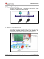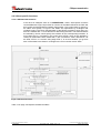
1
Rotary Encoders Linear Encoders
Motion
System
D
Seite 2 - 128
GB
Page 129 - 255
MD-300-CO-CXXX
Dezentrale Stellantriebe / Decentralized positioning drives
MD-300-CO-CXXX Series with CANopen interface
• Zusätzliche Sicherheitshinweise
• CANopen-Kommunikation
• Konfiguration / Parametrierung
• Störungsbeseitigung / Diagnose
• Additional safety instructions
• CANopen communication
• Configuration / Parameterization
• Troubleshooting / Diagnosis
TR - EMO - BA - DGB - 0010 - 02 / 01/09/2008
CANopen Handbuch / Manual
TR-Electronic GmbH
D-78647 Trossingen
Eglishalde 6
Tel.: (0049) 07425/228-0
Fax: (0049) 07425/228-33
E-mail: [email protected]
http://www.tr-electronic.de
Urheberrechtsschutz
Dieses Handbuch, einschließlich den darin enthaltenen Abbildungen, ist
urheberrechtlich geschützt. Drittanwendungen dieses Handbuchs, welche von den
urheberrechtlichen Bestimmungen abweichen, sind verboten. Die Reproduktion,
Übersetzung sowie die elektronische und fotografische Archivierung und
Veränderung bedarf der schriftlichen Genehmigung durch den Hersteller.
Zuwiderhandlungen verpflichten zu Schadenersatz.
Änderungsvorbehalt
Jegliche Änderungen, die dem technischen Fortschritt dienen, vorbehalten.
Dokumenteninformation
Ausgabe-/Rev.-Datum:
Dokument-/Rev.-Nr.:
Dateiname:
Verfasser:
01/09/2008
TR - EMO - BA - DGB - 0010 - 02
TR-EMO-BA-DGB-0010-02.DOC
MÜJ
Schreibweisen
Kursive oder fette Schreibweise steht für den Titel eines Dokuments oder wird zur
Hervorhebung benutzt.
Courier-Schrift zeigt Text an, der auf dem Display bzw. Bildschirm sichtbar ist und
Menüauswahlen von Software.
″<
> ″ weist auf Tasten der Tastatur Ihres Computers hin
(wie etwa <RETURN>).
Marken
CANopen ist ein eingetragenes Warenzeichen der CAN in Automation e.V.
CoDeSys ist ein eingetragenes Warenzeichen der 3S – Smart Software Solutions GmbH
encoTRive ist ein eingetragenes Warenzeichen der TR-Electronic GmbH
© TR-Electronic GmbH 2006, All Rights Reserved
Page 2 of 255
Printed in the Federal Republic of Germany
TR - EMO - BA - DGB - 0010 - 02
01/09/2008
Zahlendarstellungen
Präfix „0x“ zeigt an, dass eine Hexadezimalzahl folgt.
„0x0012“ ist die hexadezimale Darstellung der Dezimalzahl 18.
Suffix "bin" zeigt die Binärdarstellung einer Zahl an.
Dabei steht das Bit mit Wertigkeit 20 rechts.
„0001 0010 bin“ ist die Binärdarstellung der Dezimalzahl 18.
Literatur
CiA [2001]:
CiA Draft Standard Proposal 306. Electronic Data Sheet
Specification for CANopen. Version 1.1. Jun. 2001.
CiA [2002a]:
CiA Draft Standard 301. CANopen Application Layer and
Communication Profile. Version 4.02. Feb. 2002.
CiA [2002b]:
CiA Draft Standard Proposal 402. CANopen Device Profile Drives
and Motion Control. Version 2.0. July 2002.
© TR-Electronic GmbH 2006, All Rights Reserved
Printed in the Federal Republic of Germany
01/09/2008
TR - EMO - BA - DGB - 0010 - 02
Page 3 of 255
Inhaltsverzeichnis
Inhaltsverzeichnis
Inhaltsverzeichnis ............................................................................................................................4
Änderungs-Index ..............................................................................................................................9
1 Allgemeines ...................................................................................................................................10
1.1 Zielgruppe ............................................................................................................................10
1.2 Geltungsbereich ...................................................................................................................10
1.3 Verwendete Abkürzungen / Begriffe ....................................................................................11
2 Zusätzliche Sicherheitshinweise .................................................................................................13
2.1 Symbol- und Hinweis-Definitionen .......................................................................................13
2.2 Organisatorische Maßnahmen.............................................................................................13
3 DSP 402 Antriebsprofil .................................................................................................................14
3.1 Das Objektverzeichnis .........................................................................................................15
3.2 CANopen Objektverzeichnis ................................................................................................15
3.3 Zustandsmaschine, Status- und Steuerwort ........................................................................16
4 CANopen-Kommunikation............................................................................................................17
4.1 CANopen – Kommunikationsprofil .......................................................................................17
4.2 CANopen..............................................................................................................................19
4.2.1 Allgemeines zu CAN und CANopen ..........................................................................19
4.2.2 Rollen und Kommunikationsbeziehungen .................................................................20
4.2.2.1 SDO (Service Data Object) ..........................................................................21
4.2.2.1.1 SDO-Nachrichtenformat ..................................................................22
4.2.2.2 PDO (Process Data Object), SYNC (Synchronisation) ................................24
4.2.2.2.1 PDOs anfordern: Remote Transmission Request...........................25
4.2.2.2.2 Parameter/Objekte für PDO-Konfigurierung ...................................26
4.2.2.3 EMCY (Emergency-Dienst) ..........................................................................27
4.2.2.4 Heartbeat ......................................................................................................28
4.2.2.5 Netzwerkmanagement-Dienste ....................................................................28
4.2.2.5.1 NMT-Dienste zur Gerätekontrolle ...................................................28
4.2.2.5.2 NMT-Dienste zur Verbindungsüberwachung ..................................30
4.2.3 Antriebsspezifische Funktionen .................................................................................31
4.2.3.1 DSP 402 - Zustandsmaschine......................................................................31
4.2.3.2 Steuerwort und Zustandswort.......................................................................34
4.2.3.3 Betriebsart „Positionierrampe“......................................................................35
4.2.3.3.1 Steuerwort .......................................................................................35
4.2.3.3.2 Zustandswort ...................................................................................36
4.2.3.3.3 Positionierung durchführen .............................................................37
4.2.3.3.4 Absolute- / Relative Positionierung .................................................38
4.2.3.3.5 Übergabe neuer Fahrsätze .............................................................39
4.2.3.3.6 Abbruch einer Positionierung ..........................................................39
4.2.3.3.7 Relevante Parameter ......................................................................39
4.2.3.4 Betriebsart „Geschwindigkeitsrampe“ ..........................................................40
4.2.3.4.1 Steuerwort .......................................................................................40
4.2.3.4.2 Zustandswort ...................................................................................41
4.2.3.4.3 Geschwindigkeitsrampe ausführen .................................................42
4.2.3.4.4 Relevante Parameter ......................................................................43
© TR-Electronic GmbH 2006, All Rights Reserved
Page 4 of 255
Printed in the Federal Republic of Germany
TR - EMO - BA - DGB - 0010 - 02
01/09/2008
Inhaltsverzeichnis
4.2.3.5 Einheiten .......................................................................................................44
4.2.3.5.1 Objekt 0x608F: Positionsgeberauflösung .......................................44
4.2.3.5.2 Objekt 0x6090: Auflösung des Geschwindigkeitsgebers ................44
4.2.3.5.3 Objekt 0x6093: Positionsfaktor........................................................45
4.2.3.5.4 Objekt 0x6094: Geschwindigkeitsfaktor ..........................................47
4.2.3.5.5 Objekt 0x6097: Beschleunigungsfaktor...........................................49
4.2.4 Das Objektverzeichnis ...............................................................................................54
4.2.4.1 Objektarten, Datentypen...............................................................................54
4.2.4.2 EDS-Datei .....................................................................................................55
4.2.4.3 Erläuterungen zur Parameterliste.................................................................56
4.2.4.4 Objekte des Kommunikationsprofils DS 301 ................................................57
4.2.4.4.1 Objekt 0x1000: Gerätetyp ...............................................................57
4.2.4.4.2 Objekt 0x1001: Fehlerregister .........................................................57
4.2.4.4.3 Objekt 0x1003: Vordefiniertes Fehlerfeld........................................58
4.2.4.4.4 Objekt 0x1004: Anzahl unterstützte PDOs......................................59
4.2.4.4.5 Objekt 0x1005: COB-ID der SYNC-Nachricht.................................60
4.2.4.4.6 Objekt 0x1008: Gerätebezeichnung des Herstellers ......................60
4.2.4.4.7 Objekt 0x1009: Hardware-Version des Herstellers.........................61
4.2.4.4.8 Objekt 0x100A: Software-Version des Herstellers..........................61
4.2.4.4.9 Objekt 0x100C: Guard Time............................................................61
4.2.4.4.10 Objekt 0x100D: Life Time Factor ..................................................62
4.2.4.4.11 Objekt 0x1010: Speichern von Parametern ..................................62
4.2.4.4.12 Objekt 0x1011: Werksvoreinstellungen laden...............................64
4.2.4.4.13 Objekt 0x1014: COB-ID der EMCY-Nachricht ..............................65
4.2.4.4.14 Objekt 0x1015: Sperrzeit für EMCY ..............................................66
4.2.4.4.15 Objekt 0x1016: Consumer Heartbeat Time...................................66
4.2.4.4.16 Objekt 0x1017: Heartbeat Producer Time.....................................67
4.2.4.4.17 Objekt 0x1018: Identity Objekt-Geräteinformationen....................68
4.2.4.4.18 Objekte 0x1400-0x1405: Kommunikation, Empfangs-PDOs ........70
4.2.4.4.19 Objekte 0x1600-0x1605: Mapping, Empfangs-PDOs ...................72
4.2.4.4.20 Objekte 0x1800-0x1805: Kommunikation, Sende-PDOs..............74
4.2.4.4.21 Objekte 0x1A00-0x1A05: Mapping, Sende-PDOs ........................77
4.2.4.5 Herstellerspezifische Objekte .......................................................................79
4.2.4.5.1 Objekt 0x2E02: Temperatur / Busadresse / Baudrate ....................79
4.2.4.5.2 Objekt 0x2F02: Temperaturschwellwerte........................................82
4.2.4.5.3 Objekt 0x2F04: Kalibrierwerte .........................................................84
4.2.4.6 Objekte des Geräteprofils DSP 402 .............................................................87
4.2.4.6.1 Objekt 0x6007: Abort Connection Code..........................................87
4.2.4.6.2 Objekt 0x603F: Error Code .............................................................87
4.2.4.6.3 Objekt 0x6040: Steuerwort (Controlword).......................................87
4.2.4.6.4 Objekt 0x6041: Statuswort (Statusword).........................................88
4.2.4.6.5 Objekt 0x604D: Pol-Paar-Zahl ........................................................88
4.2.4.6.6 Objekt 0x605A: Verhalten bei Zwischenhalt ...................................89
4.2.4.6.7 Objekt 0x605B: Verhalten bei Shutdown ........................................90
4.2.4.6.8 Objekt 0x605C: Verhalten bei Disable Operation ...........................90
4.2.4.6.9 Objekt 0x605D: Verhalten bei Stop .................................................91
4.2.4.6.10 Objekt 0x605E: Verhalten bei Fehler ............................................92
4.2.4.6.11 Objekt 0x6060: Betriebsart............................................................92
4.2.4.6.12 Objekt 0x6061: Anzeige der Betriebsart .......................................93
4.2.4.6.13 Objekt 0x6062: Soll-Position .........................................................93
4.2.4.6.14 Objekt 0x6064: Ist-Position ...........................................................93
4.2.4.6.15 Objekt 0x6065: Schleppfehlerfenster ............................................94
4.2.4.6.16 Objekt 0x6066: Schleppfehler-Timeout.........................................94
4.2.4.6.17 Objekt 0x6067: Positionsfenster ...................................................94
4.2.4.6.18 Objekt 0x6068: Positionsfenster-Timeout .....................................95
4.2.4.6.19 Objekt 0x6069: Gemessene Geschwindigkeit ..............................95
4.2.4.6.20 Objekt 0x606B: Soll-Geschwindigkeit ...........................................95
4.2.4.6.21 Objekt 0x606C: Ist-Geschwindigkeit .............................................96
© TR-Electronic GmbH 2006, All Rights Reserved
Printed in the Federal Republic of Germany
01/09/2008
TR - EMO - BA - DGB - 0010 - 02
Page 5 of 255
Inhaltsverzeichnis
4.2.4.6.22 Objekt 0x6071: Ziel-Drehmoment .................................................96
4.2.4.6.23 Objekt 0x6072: Maximales Drehmoment ......................................96
4.2.4.6.24 Objekt 0x6073: Maximalstrom.......................................................97
4.2.4.6.25 Objekt 0x6074: Soll-Drehmoment .................................................97
4.2.4.6.26 Objekt 0x6075: Motor-Nennstrom .................................................97
4.2.4.6.27 Objekt 0x6076: Motor-Nenndrehmoment......................................98
4.2.4.6.28 Objekt 0x6077: Drehmoment-Istwert ............................................98
4.2.4.6.29 Objekt 0x6078: Strom-Istwert........................................................98
4.2.4.6.30 Objekt 0x6079: Spannung am Gleichspannungszwischenkreis ...99
4.2.4.6.31 Objekt 0x607A: Zielposition...........................................................99
4.2.4.6.32 Objekt 0x607B: Positionsbereich ..................................................100
4.2.4.6.33 Objekt 0x607D: Software-Positionsbereich ..................................101
4.2.4.6.34 Objekt 0x607E: Richtungsumkehr.................................................102
4.2.4.6.35 Objekt 0x607F: Maximalgeschwindigkeit ......................................102
4.2.4.6.36 Objekt 0x6080: Maximale Motorgeschwindigkeit..........................103
4.2.4.6.37 Objekt 0x6081: Geschwindigkeit...................................................103
4.2.4.6.38 Objekt 0x6083: Beschleunigung ...................................................103
4.2.4.6.39 Objekt 0x6084: Bremsbeschleunigung .........................................104
4.2.4.6.40 Objekt 0x6085: Bremsbeschleunigung für Zwischenhalt..............104
4.2.4.6.41 Objekt 0x6087: Drehmoment-Steigung.........................................104
4.2.4.6.42 Objekt 0x608F: Auflösung des Positionsgebers ...........................105
4.2.4.6.43 Objekt 0x6090: Auflösung des Geschwindigkeitsgebers..............106
4.2.4.6.44 Objekt 0x6093: Positionsfaktor .....................................................107
4.2.4.6.45 Objekt 0x6094: Geschwindigkeitsfaktor ........................................108
4.2.4.6.46 Objekt 0x6097: Beschleunigungsfaktor.........................................109
4.2.4.6.47 Objekt 0x60C5: Maximale Beschleunigung ..................................110
4.2.4.6.48 Objekt 0x60C6: Maximale Bremsbeschleunigung ........................110
4.2.4.6.49 Objekt 0x60FD: Digitale Eingänge ................................................110
4.2.4.6.50 Objekt 0x60FE: Digitale Ausgänge ...............................................111
4.2.4.6.51 Objekt 0x60FF: Ziel-Geschwindigkeit ...........................................112
4.2.4.6.52 Objekt 0x6402: Motorart................................................................112
4.2.4.6.53 Objekt 0x6502: Unterstützte Betriebsarten ...................................112
5 Beispiel einer Positionierung mit Telegrammabfolge ...............................................................113
5.1 Vorraussetzungen ................................................................................................................113
5.2 Festlegungen........................................................................................................................113
5.3 Telegrammabfolge ...............................................................................................................114
6 Störungsbeseitigung und Diagnosemöglichkeiten ...................................................................119
6.1 SDO-Fehlercodes ................................................................................................................119
6.2 EMCY-Fehlerinformation......................................................................................................120
6.2.1 Fehlerregister, Objekt 0x1001 ...................................................................................120
6.2.2 Fehlercode, Objekt 0x1003 (Bit 0-15)........................................................................121
6.2.2.1 Allgemeines ..................................................................................................121
6.2.2.2 Profilspezifischer Fehlercode, CiA DSP 402 ................................................121
6.2.2.3 Herstellerpezifischer Fehlercode ..................................................................123
© TR-Electronic GmbH 2006, All Rights Reserved
Page 6 of 255
Printed in the Federal Republic of Germany
TR - EMO - BA - DGB - 0010 - 02
01/09/2008
Inhaltsverzeichnis
Tabellenverzeichnis
Tabelle 1: Identifier mit Node ID und Funktionscode ............................................................................ 19
Tabelle 2: COB-IDs für Service Data Object (SDO).............................................................................. 21
Tabelle 3: SDO-Nachricht ..................................................................................................................... 22
Tabelle 4: Kommando-Codes für SDO ................................................................................................. 22
Tabelle 5: Parameter für PDO-Konfigurierung ...................................................................................... 26
Tabelle 6: EMCY-Nachricht................................................................................................................... 27
Tabelle 7: Parameter für EMCY ............................................................................................................ 27
Tabelle 8: Parameter für Heartbeat....................................................................................................... 28
Tabelle 9: NMT-Nachricht zur Gerätekontrolle...................................................................................... 28
Tabelle 10: NMT-Dienste zur Gerätekontrolle....................................................................................... 29
Tabelle 11: Parameter für NMT-Dienste ............................................................................................... 30
Tabelle 12: Zustände............................................................................................................................. 32
Tabelle 13: Zustandsübergänge............................................................................................................ 34
Tabelle 14: Steuerwort (Objekt 0x6040), Betriebsart „Positionierrampe“ ............................................. 35
Tabelle 15: Zustandswort (Objekt 0x6041), Betriebsart „Positionierrampe“ ......................................... 36
Tabelle 16: Positionierungs-Parameter................................................................................................. 39
Tabelle 17: Steuerwort (Objekt 0x6040), Betriebsart „Geschwindigkeitsrampe“.................................. 40
Tabelle 18: Zustandswort (Objekt 0x6041), Betriebsart „Geschwindigkeitsrampe“.............................. 41
Tabelle 19: Geschwindigkeitsrampen-Parameter ................................................................................. 43
Tabelle 20: Objektcodes bei encoTRive ............................................................................................... 54
Tabelle 21: Attribute .............................................................................................................................. 54
Tabelle 22: CANopen-Datentypen, die von encoTRive verwendet werden.......................................... 54
Tabelle 23: Übertragungsart (RPDO).................................................................................................... 71
Tabelle 24: Übertragungsart (TPDO) .................................................................................................... 75
Tabelle 25: Werte für Quick Stop Option Code..................................................................................... 89
Tabelle 26: Werte für Shutdown Option Code ...................................................................................... 90
Tabelle 27: Werte für Disable Operation Option Code ......................................................................... 90
Tabelle 28: Werte für Halt Option Code ................................................................................................ 91
Tabelle 29: Werte für Fault Reaction Option Code ............................................................................... 92
Tabelle 30: Werte für Betriebsart .......................................................................................................... 92
Tabelle 31: Richtungsumkehr.............................................................................................................. 102
Tabelle 32: SDO Fehlercodes ............................................................................................................. 119
Tabelle 33: EMCY Fehlerregister, Objekt 0x1001............................................................................... 120
Tabelle 34: Profilspezifischer EMCY Fehlercode, Objekt 1003 .......................................................... 122
Tabelle 35: Herstellerspezifischer EMCY Fehlercode, Objekt 1003................................................... 127
© TR-Electronic GmbH 2006, All Rights Reserved
Printed in the Federal Republic of Germany
01/09/2008
TR - EMO - BA - DGB - 0010 - 02
Page 7 of 255
Inhaltsverzeichnis
Abbildungsverzeichnis
Abbildung 1: CANopen Applikationsprofile ........................................................................................... 14
Abbildung 2: Aufbau des Objektverzeichnisses .................................................................................... 15
Abbildung 3: Antriebe am Feldbus ........................................................................................................ 17
Abbildung 4: Kommunikationsprofil ....................................................................................................... 17
Abbildung 5: Gegenüberstellung von PDO/SDO-Eigenschaften .......................................................... 20
Abbildung 6: PDO Mapping Parameter ................................................................................................. 24
Abbildung 7: NMT Boot-Up-Mechanismus............................................................................................ 29
Abbildung 8: DSP 402 Zustandsmaschine............................................................................................ 31
Abbildung 9: Positionierrampe .............................................................................................................. 37
Abbildung 10: Absolute Positionierung (oben) und relative Positionierung (unten).............................. 38
Abbildung 11: Geschwindigkeitsrampe ................................................................................................. 42
Abbildung 12: Auszug aus einer encoTRive-EDS ................................................................................ 55
Formelverzeichnis
Formel 1: Positionsgeberauflösung....................................................................................................... 44
Formel 2: Default-Wert, Positionsgeberauflösung ................................................................................ 44
Formel 3: Geschwindigkeitsgeberauflösung ......................................................................................... 44
Formel 4: Default-Wert, Geschwindigkeitsgeberauflösung................................................................... 44
Formel 5: Positionsfaktor....................................................................................................................... 45
Formel 6: Getriebefaktor (Gear Ratio) .................................................................................................. 45
Formel 7: Default-Wert, Positionsfaktor ................................................................................................ 45
Formel 8: Geschwindigkeitsfaktor ......................................................................................................... 47
Formel 9: Default-Wert, Geschwindigkeitsfaktor................................................................................... 47
Formel 10: Beschleunigungsfaktor........................................................................................................ 49
Formel 11: Default für Beschleunigungsfaktor ...................................................................................... 49
© TR-Electronic GmbH 2006, All Rights Reserved
Page 8 of 255
Printed in the Federal Republic of Germany
TR - EMO - BA - DGB - 0010 - 02
01/09/2008
Änderungs-Index
Änderungs-Index
Änderung
Datum
Index
Erstausgabe
21.02.06
00
27.11.07
01
09.01.08
02
Überarbeitungen
–
–
Kapitel „Einheiten“, Seite 44
Englischer Teil hinzugefügt
Überarbeitungen
–
–
Neue Fehlermeldungen: 6345, 6348, 8612
Parameteranpassungen, Standardwerte
© TR-Electronic GmbH 2006, All Rights Reserved
Printed in the Federal Republic of Germany
01/09/2008
TR - EMO - BA - DGB - 0010 - 02
Page 9 of 255
Allgemeines
1 Allgemeines
Das vorliegende Handbuch beinhaltet folgende Themen:
•
Ergänzende Sicherheitshinweise zu den bereits in der Montage-/
Installationsanleitung definierten grundlegenden Sicherheitshinweisen
•
Antriebsprofil DSP 402
•
CANopen-Kommunikation
•
Konfiguration / Parametrierung
•
Störungsbeseitigung und Diagnosemöglichkeiten
Da die Dokumentation modular aufgebaut ist, stellt dieses Handbuch eine Ergänzung
zu anderen Dokumentationen wie z.B. kundenspezifische Benutzerhandbücher,
Montage- / Installationsanleitung, Maßzeichnungen, Prospekte etc. dar.
Das Handbuch kann kundenspezifisch im Lieferumfang enthalten sein, oder kann
auch separat angefordert werden.
1.1 Zielgruppe
Die vorliegende Dokumentation richtet sich an
•
Inbetriebnahme- , Bedien- und Wartungspersonal, die beauftragt sind entsprechende Tätigkeiten am Stellantrieb vorzunehmen.
Die entsprechende Qualifikation des Personals ist in der Montage-/
Installationsanleitung in Kapitel „Personalauswahl und –qualifikation; grundsätzliche
Pflichten“ definiert.
1.2 Geltungsbereich
Das Handbuch gilt ausschließlich für folgende dezentrale Stellantriebs-Typen mit
CANopen Schnittstelle:
•
MD-300-CO-CXXX
Die Produkte sind durch aufgeklebte Typenschilder gekennzeichnet und sind
Bestandteil einer Anlage.
Es gelten somit zusammen folgende Dokumentationen:
•
anlagenspezifische Betriebsanleitungen des Betreibers,
•
dieses encoTRive CANopen-Handbuch,
•
die Montage-/Installationsanleitung TR-EMO-BA-DGB-0015,
•
das kundenspezifische Benutzerhandbuch (optional),
•
Inbetriebnahmeanleitung für
CoDeSys/PLCopen/Funktionsbausteine/Handgerät (optional)
© TR-Electronic GmbH 2006, All Rights Reserved
Page 10 of 255
Printed in the Federal Republic of Germany
TR - EMO - BA - DGB - 0010 - 02
01/09/2008
Allgemeines
1.3 Verwendete Abkürzungen / Begriffe
A
ASCII
CAN
CCD
CiA
COB
COB-ID
CPU
DIP-Schalter
DS
DSP
EDS
EMCY
encoTRive
HW
inc
mA
mm
mNm
mV
Nm
NMT
OV
PC
PDO
PI
PID
PZD
ro
RPDO
rph
rpm
rps
RTR
rw
SDO
sec
STW
STW.x
SPS
Ampere
American Standard Code for Information Interchange
Controller Area Network
Command Code
CAN in Automation e.V.
Communication Object
COB Identifier
Central Processing Unit, Zentrale Verarbeitungseinheit
Dual in-line package switch; Reihe kleiner Kippschalter
Draft Standard
Draft Standard Proposal
Electronic Data Sheet
Emergency
TR-spezifischer Begriff für den Antrieb
Hardware
Increments, Inkremente
Milliampere
Millimeter
Millinewtonmeter
Millivolt
Newtonmeter
Network Management
Objektverzeichnis
Personal Computer
Process Data Object
Proportional-Integral
Proportional-Integral-Derivative
Prozessdaten
read only
Receive PDO (Empfangs-PDO)
Revolutions per hour, Umdrehungen pro Stunde
Revolutions per minute, Umdrehungen pro Minute
Revolutions per second, Umdrehungen pro Sekunde
Remote Transmission Request
read/write
Service Data Object
second, Sekunde
Steuerwort
Bit x des Steuerworts
Speicherprogrammierbare Steuerung
© TR-Electronic GmbH 2006, All Rights Reserved
Printed in the Federal Republic of Germany
01/09/2008
TR - EMO - BA - DGB - 0010 - 02
Page 11 of 255
Allgemeines
SW
SYNC
TPDO
V
wo
ZSW
ZSW.x
Software
Synchronization
Transmit PDO (Sende-PDO)
Volt
write only
Zustandswort
Bit x des Zustandsworts
© TR-Electronic GmbH 2006, All Rights Reserved
Page 12 of 255
Printed in the Federal Republic of Germany
TR - EMO - BA - DGB - 0010 - 02
01/09/2008
Zusätzliche Sicherheitshinweise
2 Zusätzliche Sicherheitshinweise
2.1 Symbol- und Hinweis-Definitionen
WARNUNG !
VORSICHT !
bedeutet, dass Tod, schwere Körperverletzung oder erheblicher
Sachschaden eintreten können, wenn die entsprechenden
Vorsichtsmaßnahmen nicht getroffen werden.
bedeutet, dass eine leichte Körperverletzung oder ein
Sachschaden eintreten kann, wenn die entsprechenden
Vorsichtsmaßnahmen nicht getroffen werden.
bezeichnet wichtige Informationen bzw. Merkmale und Anwendungstipps des verwendeten Produkts.
2.2 Organisatorische Maßnahmen
•
Dieses Handbuch muss ständig am Einsatzort des encoTRives griffbereit
aufbewahrt werden.
•
Das mit Tätigkeiten am encoTRive beauftragte Personal muss vor
Arbeitsbeginn
- die
Montage-/Installationsanleitung,
insbesondere
das
Kapitel
„Grundlegende Sicherheitshinweise“,
- und
dieses Handbuch, insbesondere das Kapitel „Zusätzliche
Sicherheitshinweise“,
gelesen und verstanden haben.
Dies gilt in besonderem Maße für nur gelegentlich, z.B. bei der Parametrierung des
encoTRives, tätig werdendes Personal.
© TR-Electronic GmbH 2006, All Rights Reserved
Printed in the Federal Republic of Germany
01/09/2008
TR - EMO - BA - DGB - 0010 - 02
Page 13 of 255
DSP 402 Antriebsprofil
3 DSP 402 Antriebsprofil
Die
Sprachmittel
zur
Ansteuerung
eines
Antriebs
sind
weitgehend
herstellerunabhängig. Aus diesem Grunde wurde die Kommunikation zwischen
Antrieb und übergeordneter Steuerung in so genannten Antriebsprofilen
standardisiert.
Ein Antriebsprofil spezifiziert, wie ein elektrischer Antrieb über einen Feldbus
angesteuert wird. Es definiert das Geräteverhalten und das Zugriffsverfahren auf die
Antriebsdaten. Insbesondere werden folgende Teilbereiche geregelt:
•
Steuerung und Statusüberwachung
•
standardisierte Parametrierung
•
Wechsel von Betriebsarten
encoTRive unterstützt als CAN-Teilnehmer das Profil DSP 402 (CiA [2002b])
Zwischen einem Master (z.B. Steuerung) und einem Antrieb, der eine „Slave“Funktion einnimmt, werden typischerweise folgende Informationen ausgetauscht:
Der Antrieb teilt seinen aktuellen Zustand (z.B. „Antrieb fährt“) und eventuell
zusätzliche Information wie die aktuelle Position, die aktuelle Geschwindigkeit usw.
mit. In Gegenrichtung erteilt die Steuerung beispielsweise Positionieraufträge („Fahre
mit Geschwindigkeit x an die Position y“). Ohne das DSP 402 Profil müsste jeder
Hersteller eigene Protokolle zur Übermittlung von Befehlen und Statusmeldungen
spezifizieren, und es gäbe entsprechend viele Anwendungen, die auf jeweils
unterschiedliche Art und Weise immer das gleiche leisten.
Abbildung 1: CANopen Applikationsprofile
© TR-Electronic GmbH 2006, All Rights Reserved
Page 14 of 255
Printed in the Federal Republic of Germany
TR - EMO - BA - DGB - 0010 - 02
01/09/2008
DSP 402 Antriebsprofil
3.1 Das Objektverzeichnis
Grundlegend bei Antriebsprofilen ist das Objektverzeichnis (OV). Im OV sind
sämtliche Informationen (Parameter) zusammengefasst, die für ein Gerät relevant
sind. Ein Parameter wird durch seine Parameternummer (16 Bit) identifiziert.
Bestimmte Bereiche für die Parameternummer sind belegt bzw. reserviert, andere
stehen für so genannte herstellerspezifische Parameter zur Verfügung.
Unter den vordefinierten Parameter gibt es optionale Parameter und solche, die von
jedem profilkonformen Slave zu unterstützen sind („Mandatory Parameters“).
3.2 CANopen Objektverzeichnis
Bei CiA wird das OV als anwendungsneutrales Konzept angesehen. Entsprechend
wird der Aufbau des OV und der Zugriff auf die darin enthaltenen Objekte im Rahmen
eines separaten Standards, nämlich des Draft Standard 301 (DS 301; CANopen ,
Application Layer and Communication Profile, CiA [2002a]) spezifiziert. Darauf
setzen anwendungsspezifische Standards wie DSP 402 oder der Standard für
Encoder (DS 406) auf. Innerhalb eines bestimmten Profils haben bestimmte
Parameter definierte Funktion. Für Parameternummern wird generell die
hexadezimale Notation verwendet. Im Rahmen von CANopen ist für die
Parameternummer auch die Bezeichnung Index üblich. Der Parameterbereich
0x0001-0x1FFF wird von DS 301 für Parameter belegt, die allen CANopen-Geräten
gemeinsam sind. Der Bereich 0x6000-0x9FFF steht den standardisierten
Geräteprofilen zur Verfügung. Bei DSP 402 hat z.B. die Zielposition die
Parameternummer 0x607A. In Fehlersituationen sind allgemeine Fehlerursachen
innerhalb von DS 301 definiert, und jedes Profil spezifiziert weitere, profilspezifische
Fehlernummern.
Abbildung 2: Aufbau des Objektverzeichnisses
© TR-Electronic GmbH 2006, All Rights Reserved
Printed in the Federal Republic of Germany
01/09/2008
TR - EMO - BA - DGB - 0010 - 02
Page 15 of 255
DSP 402 Antriebsprofil
3.3 Zustandsmaschine, Status- und Steuerwort
Ein zentrales Element im Antriebsprofil ist die Zustandsmaschine. Hier werden die
Betriebszustände und die Zustandsübergänge definiert. Es wird festgelegt, welche
Zustände das Gerät nach dem Einschalten durchläuft, und wie es in den Zustand
„Betriebsbereit“ überführt wird, so dass z.B. eine Positionierung durchgeführt
werden kann.
Die meisten Zustandsübergänge werden vom Master sequenziell veranlasst, indem
dieser im Steuerwort bestimmte Befehle in Form von Bitmuster absetzt.
© TR-Electronic GmbH 2006, All Rights Reserved
Page 16 of 255
Printed in the Federal Republic of Germany
TR - EMO - BA - DGB - 0010 - 02
01/09/2008
CANopen-Kommunikation
4 CANopen-Kommunikation
Alle Signale und Informationen, die für die Ansteuerung des elektrischen Antriebs
erforderlich sind, werden über den Feldbus übertragen.
Abbildung 3: Antriebe am Feldbus
4.1 CANopen – Kommunikationsprofil
Das CANopen Kommunikationsprofil (dokumentiert in CiA DS 301) regelt wie die
Geräte Daten miteinander austauschen. Hierbei werden Echtzeitdaten und
Parameterdaten unterschieden. CANopen ordnet diesen, vom Charakter her völlig
unterschiedlichen Datenarten, jeweils passende Kommunikationselemente zu.
Abbildung 4: Kommunikationsprofil
© TR-Electronic GmbH 2006, All Rights Reserved
Printed in the Federal Republic of Germany
01/09/2008
TR - EMO - BA - DGB - 0010 - 02
Page 17 of 255
CANopen-Kommunikation
Special Function Object (SFO)
-
Synchronization (SYNC)
Emergency (EMCY) Protokoll
Network Management Object (NMO)
z.B.
-
Life / Node-Guarding
Boot-Up, …
Error Control Protokoll
© TR-Electronic GmbH 2006, All Rights Reserved
Page 18 of 255
Printed in the Federal Republic of Germany
TR - EMO - BA - DGB - 0010 - 02
01/09/2008
CANopen-Kommunikation
4.2 CANopen
4.2.1 Allgemeines zu CAN und CANopen
Der CAN-Bus ist ein Multi-Master-System, bei dem jeder Teilnehmer selbstständig
Daten senden kann. Es kann vorkommen, dass mehrere Teilnehmer gleichzeitig
senden. In diesem Fall setzt sich bei CAN die Nachricht mit der höheren Priorität
durch. Die Priorität einer Nachricht wird durch den so genannten Identifier festgelegt,
welcher am Beginn der Nachricht übertragen wird. Der Identifier hat bei CAN 2.0A
eine Länge von 11 Bit, bei CAN 2.0B eine Länge von 29 Bit.
encoTRive verwendet den 11-Bit-Identifier gemäß CAN 2.0A.
Die Priorität einer Nachricht ist umso höher, je kleiner der Identifier ist.
Ein Teilnehmer kann mehrere Identifier verwenden und damit verschiedenartige
Nachrichten senden. Es muss jedoch sichergestellt sein, dass die Identifier
verschiedener Teilnehmer unterschiedlich sind.
Um zu verhindern, dass eine hochpriore Nachricht den Bus permanent belegt und so
die Übertragung von Nachrichten niedriger Priorität verhindert, kann man einem
Identifier eine so genannte Inhibit Time zuordnen. Diese definiert die Mindestpause,
die zwischen zwei Übertragungen einer Nachricht mit dem gleichen Identifier liegen
muss.
Um in diesem nachrichtenbasierten System auch Teilnehmer ansprechen zu können,
wie es insbesondere erforderlich ist, wenn bei einem Antrieb eine Positionierung
gestartet werden soll, wird der Identifier bei CANopen in zwei Teile zerlegt:
Die niederwertigen 7 Bit enthalten die Knotenadresse (Node ID), die restlichen Bit den so genannten
Funktionscode, der den Zweck der Nachricht angibt:
Funktionscode
Bit 10
Bit 9
Bit 8
Node ID
Bit 7
Bit 6
Bit 5
Bit 4
Bit 3
Bit 2
Bit 1
Bit 0
Tabelle 1: Identifier mit Node ID und Funktionscode
Bei CANopen wird der so aufgeteilte Identifier als COB-ID (Communication Object
Identifier) bezeichnet. Da der Funktionscode die höherwertigen Bits der COB-ID
belegt, steuert der Funktionscode die Übertragungsprioritäten:
Je kleiner der Funktionscode, umso höher die Priorität.
Die Node ID identifiziert einen Teilnehmer in einem CANopen-Netzwerk.
Beim encoTRive werden die Node ID und Übertragungsgeschwindigkeit fest über
DIP-Schalter eingestellt, definiert in den gerätespezifischen Steckerbelegungen.
CANopen verwendet bei der Übertragung von Zahlenwerten stets das Little Endian
Format:
Das niederwertige Byte wird in der Nachricht zuerst abgelegt.
© TR-Electronic GmbH 2006, All Rights Reserved
Printed in the Federal Republic of Germany
01/09/2008
TR - EMO - BA - DGB - 0010 - 02
Page 19 of 255
CANopen-Kommunikation
4.2.2 Rollen und Kommunikationsbeziehungen
In einem CAN-Telegramm können 8 Byte Nutzdaten transportiert werden. CANopen
definiert verschiedene Sprachmittel zur Übertragung von Prozessdaten und
Bedarfsdaten. Für Prozessdaten werden so genannte PDOs (Process Data Objects)
verwendet, für Bedarfsdaten die SDOs (Service Data Objects).
Obwohl der CAN-Bus an sich ein System von Gleichberechtigten darstellt (MultiMaster-System), gibt es bei CANopen verschiedene Rollen, von denen einige
typischerweise von einer Steuerung wahrgenommen werden, andere typischerweise
von einem Teilnehmer wie einem Antrieb.
Wichtige Merkmale von SDO und PDO
CiA DS-301 CANopen
Datenarten Kommunikationsprofil
PDO
? Echtzeitdaten
? hochpriore Identifier
? max. 8 Bytes
? Format vorher vereinbart
? CAN pur
? keine Bestätigung
SDO
? System-Parameter
? niederpriore Identifier
? Daten auf mehrere
Telegramme verteilt
? Daten durch Index
adressiert
? bestätigende Dienste
Abbildung 5: Gegenüberstellung von PDO/SDO-Eigenschaften
© TR-Electronic GmbH 2006, All Rights Reserved
Page 20 of 255
Printed in the Federal Republic of Germany
TR - EMO - BA - DGB - 0010 - 02
01/09/2008
CANopen-Kommunikation
4.2.2.1 SDO (Service Data Object)
Mit SDOs können Objekte gelesen oder geschrieben werden. Es handelt sich um
einen bestätigten Dienst. Der so genannte SDO Client spezifiziert in seiner
Anforderung „Request“ den Parameter, die Zugriffsart (Lesen/Scheiben) und
gegebenenfalls den Wert. Der so genannte SDO Server führt den Schreib- oder
Lesezugriff aus und beantwortet die Anforderung mit einer Antwort „Response“. Im
Fehlerfall gibt ein Fehlercode Auskunft über die Fehlerursache. Sende-SDO und
Empfangs-SDO werden durch ihre Funktionscodes unterschieden.
encoTRive stellt einen SDO Server dar und verwendet folgende Funktionscodes für SDOs:
Funktionscode
COB-ID
Bedeutung
11 (1011 bin)
0x580 + Node ID
encoTRive → SDO Client
12 (1100 bin)
0x600 + Node ID
SDO Client → encoTRive
Tabelle 2: COB-IDs für Service Data Object (SDO)
Beispiel:
Node ID encoTRive: 112 (0x70)
•
Eine Nachricht mit COB-ID 0x5F0 (= 0x580+0x70) entspricht einem SDO vom
encoTRive an den SDO Client.
•
Eine Nachricht mit COB-ID 0x670 (=0x600+0x70) entspricht einem SDO vom
SDO Client an den encoTRive.
© TR-Electronic GmbH 2006, All Rights Reserved
Printed in the Federal Republic of Germany
01/09/2008
TR - EMO - BA - DGB - 0010 - 02
Page 21 of 255
CANopen-Kommunikation
4.2.2.1.1 SDO-Nachrichtenformat
Der maximal 8 Byte lange Datenbereich einer CAN-Nachricht wird von einem SDO wie folgt belegt:
CCD
Byte 0
Index
Byte 1
Subindex
Byte 2
Byte 3
Daten
Byte 4
Byte 5
Byte 6
Byte 7
Tabelle 3: SDO-Nachricht
Der Kommando-Code (CCD) identifiziert bei der SDO Request, ob gelesen oder
geschrieben werden soll. Bei einem Schreibauftrag wird zusätzlich die Anzahl der zu
schreibenden Bytes im CCD kodiert.
Bei der SDO Response zeigt der CCD an, ob die Request erfolgreich war. Im Falle
eines Leseauftrags gibt der CCD zusätzlich Auskunft über die Anzahl der gelesenen
Bytes:
CCD
Bedeutung
Gültig für
0x23
4 Byte schreiben
SDO Request
0x27
3 Byte schreiben
SDO Request
0x2B
2 Byte schreiben
SDO Request
0x2F
1 Byte schreiben
SDO Request
0x60
Schreiben erfolgreich
SDO Response
0x80
Fehler
SDO Response
0x40
Leseanforderung
SDO Request
0x43
4 Byte Daten
SDO Response auf Leseanforderung
0x47
3 Byte Daten
SDO Response auf Leseanforderung
0x4B
2 Byte Daten
SDO Response auf Leseanforderung
0x40
1 Byte Daten
SDO Response auf Leseanforderung
Tabelle 4: Kommando-Codes für SDO
Im Fall eines Fehlers (SDO Response CCD = 0x80) enthält der Datenbereich einen
4-Byte-Fehlercode, der über die Fehlerursache Auskunft gibt. Die Bedeutung der
Fehlercodes ist aus der Tabelle 32, Seite 119 zu entnehmen.
© TR-Electronic GmbH 2006, All Rights Reserved
Page 22 of 255
Printed in the Federal Republic of Germany
TR - EMO - BA - DGB - 0010 - 02
01/09/2008
CANopen-Kommunikation
Beispiele:
1. In der folgenden Aufzeichnung werden zuerst die COB-ID, danach die
Nachrichtenlänge und schließlich der Datenbereich der CAN-Nachricht
dargestellt.
670
5F0
8
8
40 18 10 04 00 00 00 00
43 18 10 04 01 00 00 00
Die erste Nachricht hat COB-ID 0x670 und ist somit eine SDO vom Client an
den Teilnehmer mit Adresse 0x70. Es handelt sich um eine Leseanforderung
(CCD = 0x40) für den Parameter 0x1018, Subindex 4 (Little Endian Format).
Die zweite Nachricht hat COB-ID 0x5F0 (=0x580+0x70). Es handelt sich also
um eine SDO Response vom Teilnehmer mit Adresse 0x70 an den SDO
Client. Es wurden 4 Byte Daten gelesen und der Parameterwert ist
0x0000 0001.
2. 670
5F0
8
8
40 60 60 00 00 00 00 00
80 60 60 00 01 00 01 06
Die erste Nachricht ist eine Leseanforderung des SDO Client an den
Teilnehmer 0x70 für den Parameter 0x6060, Subindex 0. Die zweite
Nachricht ist die Antwort des Teilnehmers. CCD 0x80 zeigt an, dass die
Anforderung nicht ausgeführt werden konnte. Als Fehlercode wird
0x0601 0001 angegeben. Entsprechend der Tabelle 32 wurde versucht, ein
Objekt zu lesen, für welches nur Schreibzugriff erlaubt ist.
encoTRive unterstützt auch die SDO-Übertragung von Daten mit mehr als 4 Byte
Länge. Bei dieser segmentierten Übertragung sind mehrere Nachrichten zum
Datentransfer erforderlich.
© TR-Electronic GmbH 2006, All Rights Reserved
Printed in the Federal Republic of Germany
01/09/2008
TR - EMO - BA - DGB - 0010 - 02
Page 23 of 255
CANopen-Kommunikation
4.2.2.2 PDO (Process Data Object), SYNC (Synchronisation)
Mit einer speziellen Nachricht, der SYNC-Nachricht, kann ein so genanner SYNC
Producer alle Teilnehmer erreichen und so den Nachrichtenaustausch
synchronisieren.
encoTRive ist ein SYNC Consumer, kann also nur SYNC-Nachrichten
empfangen und darauf reagieren.
Ein
CANopen-Slave
geht
nach
dem
Einschalten
in
den
Zustand
„PRE-OPERATIONAL“. In diesem Zustand dürfen SDOs, aber keine PDOs
übertragen werden, und es ist möglich, PDOs unter Nutzung von SDOs zu
konfigurieren. Bei PDOs kann der gesamte Nutzdatenbereich der CAN-Nachricht (8
Byte) zur Übertragung von Parameterwerten verwendet werden.
encoTRive unterstützt in jeder Übertragungsrichtung bis zu sechs PDOs.
Mit speziellen Parametern, den PDO Mapping Parametern (Abbildung 6), wird der
Aufbau und die Inhalte die mit einer PDO transportiert werden festgelegt.
Abbildung 6: PDO Mapping Parameter
Dieses so genannte PDO Mapping spezifiziert, welche Parameter in welcher
Reihenfolge in einer PDO übertragen werden. Abbildung 6 zeigt das Mapping für
Empfangs-PDO 1 (RPDO1) und Empfangs-PDO 2 (RPDO2) aus Sicht des Antriebs:
In RPDO1 wird nur das Objekt 0x6040 (Steuerwort) übertragen. RPDO2 besteht aus
Objekt 0x6040 und zusätzlich aus dem Objekt 0x607A (Zielposition).
© TR-Electronic GmbH 2006, All Rights Reserved
Page 24 of 255
Printed in the Federal Republic of Germany
TR - EMO - BA - DGB - 0010 - 02
01/09/2008
CANopen-Kommunikation
Zusätzlich kann mit den PDO Communication Parametern festgelegt werden, unter
welchen Bedingungen eine PDO übertragen werden soll und wann ein übertragener
Wert intern verarbeitet werden soll:
•
Synchrone Übertragung:
In diesem Fall sendet ein Teilnehmer, der SYNC Producer, periodisch eine
SYNC-Nachricht, mit welcher die Nachrichtenübertragung netzweit
synchronisiert werden kann. Bei einer PDO, die für synchrone Übertragung
konfiguriert ist, ist das Senden und die Verarbeitung der empfangenen Daten
an die SYNC-Nachricht gebunden.
•
Asynchrone Übertragung:
Die Übertragung der Daten ist nicht an die SYNC-Nachricht gebunden. Sie
erfolgt ereignisgesteuert.
Auf diese Weise kann eine Sende-PDO ereignisgesteuert konfiguriert werden. In
diesem Fall wird die PDO gesendet, wenn sich der in der PDO übertragene
Parameterwert geändert hat. Alternativ kann eine PDO dann gesendet werden, wenn
die Übertragung durch eine SYNC-Nachricht angefordert wird. Empfangsseitig kann
ebenfalls eine synchrone Verarbeitung einer PDO konfiguriert werden. Dies bedeutet,
dass die Daten erst verarbeitet werden, wenn die nächste SYNC-Nachricht
empfangen wird. Auf diese Weise können z.B. mehrere Antriebe gleichzeitig gestartet
werden.
PDOs dürfen erst übertragen werden, wenn ein Slave im Zustand „OPERATIONAL“
ist. Im Zustand „PRE-OPERATIONAL“ kann per SDO das PDO Mapping und die
Übertragungsart eingestellt werden, bevor der Slave in den Zustand OPERATIONAL
übergeführt wird und damit die PDO-Übertragung beginnt.
4.2.2.2.1 PDOs anfordern: Remote Transmission Request
Ein PDO Consumer kann über über die Remote Transmission Request PDONachrichten von einem PDO Producer anfordern. Dazu sendet der Consumer eine
Nachricht mit der COB-ID der angeforderten PDO, wobei das RTR-Bit der CANNachricht auf 1 gesetzt ist. Dies kennzeichnet eine PDO-Anforderung. Ist der PDO
Producer so konfiguriert (Übertragungsart), dass er auf derartige Anforderungen
reagieren soll, so sendet er die betreffende PDO, wobei das RTR-Bit auf 0 gesetzt ist.
© TR-Electronic GmbH 2006, All Rights Reserved
Printed in the Federal Republic of Germany
01/09/2008
TR - EMO - BA - DGB - 0010 - 02
Page 25 of 255
CANopen-Kommunikation
4.2.2.2.2 Parameter/Objekte für PDO-Konfigurierung
Die folgende Tabelle enthält die Objekte, die für die PDO-Konfigurierung relevant
sind. Die Details werden bei den Erläuterungen zu den individuellen Parametern ab
Kapitel 4.2.4.4 „Objekte des Kommunikationsprofils DS 301“ Seite 57 beschrieben.
Objekt Nr.
Beschreibung
0x1004
Anzahl unterstützte PDOs
0x1005
COB-ID der SYNC-Nachricht
0x1400
Parameter für RPDO1: COB-ID, Übertragungsart
0x1401
Parameter für RPDO2: COB-ID, Übertragungsart
0x1402
Parameter für RPDO3: COB-ID, Übertragungsart
0x1403
Parameter für RPDO4: COB-ID, Übertragungsart
0x1404
Parameter für RPDO5: COB-ID, Übertragungsart
0x1405
Parameter für RPDO6: COB-ID, Übertragungsart
0x1600
Mapping für RPDO1
0x1601
Mapping für RPDO2
0x1602
Mapping für RPDO3
0x1603
Mapping für RPDO4
0x1604
Mapping für RPDO5
0x1605
Mapping für RPDO6
0x1800
Parameter für TPDO1: COB-ID, Übertragungsart, Inhibit Time
0x1801
Parameter für TPDO2: COB-ID, Übertragungsart, Inhibit Time
0x1802
Parameter für TPDO3: COB-ID, Übertragungsart, Inhibit Time
0x1803
Parameter für TPDO4: COB-ID, Übertragungsart, Inhibit Time
0x1804
Parameter für TPDO5: COB-ID, Übertragungsart, Inhibit Time
0x1805
Parameter für TPDO6: COB-ID, Übertragungsart, Inhibit Time
0x1A00
Mapping für TPDO1
0x1A01
Mapping für TPDO2
0x1A02
Mapping für TPDO3
0x1A03
Mapping für TPDO4
0x1A04
Mapping für TPDO5
0x1A05
Mapping für TPDO6
Tabelle 5: Parameter für PDO-Konfigurierung
© TR-Electronic GmbH 2006, All Rights Reserved
Page 26 of 255
Printed in the Federal Republic of Germany
TR - EMO - BA - DGB - 0010 - 02
01/09/2008
CANopen-Kommunikation
4.2.2.3 EMCY (Emergency-Dienst)
Mit der EMCY-Nachricht werden interne Gerätefehler gemeldet. Da PDOs einen
unbestätigten Dienst darstellen, kann z.B. ein ungültiger Parameterwert, der über
PDO eingestellt wird, zu einer EMCY-Nachricht führen. Andere typische Ereignisse,
die über EMCY gemeldet werden, sind Überlastsituationen oder Übertemperatur.
encoTRive kann EMCY-Nachrichten senden, aber keine EMCY-Nachrichten
empfangen.
Bei einer EMCY-Nachricht werden die 8 Byte Nutzdaten der CAN-Nachricht für
Informationen über die Fehlerursache genutzt:
Fehler-Code
Byte 0
Fehlerregister
Byte 1
Byte 2
Herstellerspezifische Fehlerinformation
Byte 3
Byte 4
Byte 5
Byte 6
Byte 7
Tabelle 6: EMCY-Nachricht
encoTRive verwendet das Feld „Herstellerspezifische Fehlerinformation“ nicht.
Objekt Nr.
Beschreibung
0x1001
Fehlerregister.
Speichert den Wert des Felds „Fehlerregister“ der letzten EMCY-Nachricht
0x1003
Pre-defined Error-Field.
Speichert die Inhalte des Feldes „Fehler-Code“ der letzten EMCY-Nachrichten. Es
können die letzten 8 Fehler-Codes gespeichert werden. Mit jeder neuen EMCYNachricht gelangen die älteren Fehler-Codes einen Index nach hinten.
0x1014
COB-ID der EMCY-Nachricht
Tabelle 7: Parameter für EMCY
Die Bedeutung der verschiedenen EMCY-Fehlerinformationen kann aus Tabelle 33
und Tabelle 34 ab Seite 120 entnommen werden.
Boot-Up-Nachricht
Das CANopen-Profil definiert eine Zusatzfunktion der EMCY-Nachricht:
Eine EMCY-Nachricht ohne Datenfeld stellt eine Boot-Up-Nachricht dar, mit welcher
ein Teilnehmer nach dem Einschalten allen anderen Teilnehmern signalisiert, dass er
betriebsbereit ist.
© TR-Electronic GmbH 2006, All Rights Reserved
Printed in the Federal Republic of Germany
01/09/2008
TR - EMO - BA - DGB - 0010 - 02
Page 27 of 255
CANopen-Kommunikation
4.2.2.4 Heartbeat
Das Heartbeat-Protokoll ist ein Protokoll zur Fehlererkennung. Der Heartbeat
Producer sendet dabei eine zyklische Nachricht mit einer niedrigen Priorität. Diese
Nachricht wird von mehreren Teilnehmern (Heartbeat Consumer) empfangen und
ausgewertet. Bleibt die Heartbeat-Nachricht aus, so wird eine entsprechende EMCYNachricht gesendet.
encoTRive kann als Heartbeat Producer und als Heartbeat Consumer arbeiten.
Objekt Nr.
Beschreibung
0x1016
Consumer Heartbeat Time
Festlegung des Zeitintervalls, innerhalb dessen eine Heartbeat-Nachricht erwartet wird.
0x1017
Producer Heartbeat Time
Zeitintervall für das Senden einer Heartbeat Nachricht.
Tabelle 8: Parameter für Heartbeat
4.2.2.5 Netzwerkmanagement-Dienste
Das Network Management (NMT) hat die Aufgabe, Teilnehmer eines CANopenNetzwerks zu initialisieren, die Teilnehmer in das Netz aufzunehmen, zu stoppen und
zu überwachen.
NMT-Dienste werden von einem NMT-Master initiiert, der einzelne Teilnehmer (NMTSlave) über deren Node ID anspricht. Eine NMT-Nachricht mit der Node ID 0 richtet
sich an alle NMT-Slaves.
encoTRive ist ein NMT-Slave.
4.2.2.5.1 NMT-Dienste zur Gerätekontrolle
Die NMT-Dienste zur Gerätekontrolle verwendet die COB-ID 0 und erhalten so die
höchste Priorität.
Vom Datenfeld der CAN-Nachricht werden nur die ersten beiden Byte verwendet:
Kommando
Node ID
Byte 0
Byte 1
Tabelle 9: NMT-Nachricht zur Gerätekontrolle
© TR-Electronic GmbH 2006, All Rights Reserved
Page 28 of 255
Printed in the Federal Republic of Germany
TR - EMO - BA - DGB - 0010 - 02
01/09/2008
CANopen-Kommunikation
Folgende Kommandos sind definiert:
Kommando Bedeutung
Zustand
-
Automatische Initialisierung nach dem Einschalten
(1)
-
Beendigung der Initialisierung --> PRE-OPERATIONAL
(2)
0x01
Start Remote Node
Teilnehmer soll in den Zustand OPERATIONAL wechseln und damit
den normalen Netzbetrieb starten
(3),(6)
0x02
Stop Remote Node
Teilnehmer soll in den Zustand STOPPED übergehen und damit seine
Kommunikation stoppen. Eine aktive Verbindungsüberwachung bleibt
aktiv.
(5),(8)
0x80
Enter PRE-OPERATIONAL
Teilnehmer soll in den Zustand PRE-OPERATIONAL gehen. Alle
Nachrichten außer PDOs können verwendet werden.
(4),(7)
0x81
Reset Node
Werte der Profilparameter des OV auf Default-Werte setzen. Danach
Übergang in den Zustand RESET COMMUNICATION.
(9),(10),(11)
0x82
Reset Communication
Teilnehmer soll in den Zustand RESET COMMUNICATION gehen und
die Werte der Kommunikationsparameter des OV mit Default-Werten (12),(13),(14)
laden. Danach Übergang in den Zustand INITIALIZATION, erster
Zustand nach Einschalten.
Tabelle 10: NMT-Dienste zur Gerätekontrolle
Power ON or Hardware Reset
(1)
Initialization
(2)
(14)
(11)
Pre-Operational
(7)
(13)
(4)
(3)
(12)
(10)
(5)
Stopped
(6)
(8)
(9)
Operational
Abbildung 7: NMT Boot-Up-Mechanismus
© TR-Electronic GmbH 2006, All Rights Reserved
Printed in the Federal Republic of Germany
01/09/2008
TR - EMO - BA - DGB - 0010 - 02
Page 29 of 255
CANopen-Kommunikation
4.2.2.5.2 NMT-Dienste zur Verbindungsüberwachung
Mit der Verbindungsüberwachung kann ein NMT-Master den Ausfall eines NMT-Slave
und/oder ein NMT-Slave den Ausfall des NMT-Master erkennen:
•
Node Guarding:
Mit diesem Dienst überwacht ein NMT-Master einen NMT-Slave
•
Life Guarding:
Mit diesem Dienst überwacht ein NMT-Slave einen NMT-Master
Das Node Guarding wird dadurch realisiert, dass der NMT-Master in regelmäßigen
Abständen den Zustand eines NMT-Slave anfordert. Kommt innerhalb eines
bestimmten Zeitintervalls keine Rückmeldung, so geht der NMT-Master von einem
Ausfall des NMT-Slave aus.
Ist das Life Guarding aktiv, erwartet der NMT-Slave innerhalb eines bestimmten
Zeitintervalls eine derartige Zustandsabfrage durch den NMT-Master.
Die NMT-Dienste zur Verbindungsüberwachung verwenden den Funktionscode
1110 bin, also die COB-ID 0x700+Node ID.
Objekt Nr.
Beschreibung
0x100C
Guard Time [ms]
0x100D
Life Time Factor
Spätestens nach Ablauf des Zeitintervalls
Life Time = Guard Time x Life Time Factor [ms]
erwartet der NMT-Slave eine Zustandsabfrage durch den
Master.
Ist die Guard Time = 0, wird der entsprechende NMT-Slave
nicht vom Master überwacht.
Ist die Life Time = 0, ist das Life Guarding abgeschaltet.
Tabelle 11: Parameter für NMT-Dienste
© TR-Electronic GmbH 2006, All Rights Reserved
Page 30 of 255
Printed in the Federal Republic of Germany
TR - EMO - BA - DGB - 0010 - 02
01/09/2008
CANopen-Kommunikation
4.2.3 Antriebsspezifische Funktionen
4.2.3.1 DSP 402 - Zustandsmaschine
Ist der Antrieb als CANopen-Slave im Zustand OPERATIONAL, können
antriebsspezifische Funktionen angesprochen werden. Abbildung 8 gibt einen
Überblick über die im Antriebsprofil DSP 402 definierten Zustände und die Übergänge
zwischen diesen Zuständen. Der aktuelle Zustand kann dem Zustandswort (ZSW)
entnommen werden. In Abbildung 8 sind die Zustände durch Rechtecke mit
gerundeten Ecken dargestellt. Dabei ist jeweils die Binärdarstellung des ZSW
angegeben. Ein Bit, welches mit 'x' gekennzeichnet ist, ist für die Zustandsermittlung
nicht relevant. Die Zustandsübergänge sind durch Pfeile gekennzeichnet, an denen
die Bedingung für den entsprechenden Übergang angegeben ist. In den meisten
Fällen handelt es sich dabei um ein Kommando im Steuerwort (STW), welches
ebenfalls durch gewisse Bitkombinationen definiert ist. Mit 'x' gekennzeichnete Bits
sind dabei nicht relevant. STW.x bezeichnet Bit x des STW, STW.7: 0->1 bedeutet
„steigende Flanke STW.7“. In einer Fehlersituation gelangt man aus jedem der
Zustände im eingezeichneten Rechteck in den Zustand „Fehlerreaktion aktiv“.
Abbildung 8: DSP 402 Zustandsmaschine
Tabelle 12 auf Seite 32 erläutert die verschiedenen Zustände.
© TR-Electronic GmbH 2006, All Rights Reserved
Printed in the Federal Republic of Germany
01/09/2008
TR - EMO - BA - DGB - 0010 - 02
Page 31 of 255
CANopen-Kommunikation
Zustand
Bedingung
Beschreibung
Nicht einschaltbereit
ZSW = xxxx xxxx x0xx 0000
(Not Ready to switch on)
Der Antrieb befindet sich in der
Initialisierungsphase.
Einschaltsperre
(Switch on disabled)
ZSW = xxxx xxxx x1xx 0000
Initialisierung des Antriebs beendet.
Die Endstufe kann nicht eingeschaltet
werden.
Einschaltbereit
(Ready to switch on)
ZSW = xxxx xxxx x01x 0001
Die Endstufe kann eingeschaltet werden.
Antriebsparameter können geändert
werden.
Eingeschaltet
(Switched on)
ZSW = xxxx xxxx x01x 0011
Endstufe eingeschaltet.
Der Antrieb kann gemäß der eingestellten
Betriebsart verwendet werden:
Betriebsbereit
(Operation enabled)
ZSW = xxxx xxxx x01x 0111
Betriebsart Positionierrampe:
Zielposition kann übernommen werden.
Betriebsart Geschwindigkeitsrampe:
Antrieb beschleunigt auf die
vorgegebene Zielgeschwindigkeit.
Zwischenhalt
(Quick stop active)
ZSW = xxxx xxxx x00x 0111
Der Antrieb führt einen Zwischenhalt aus.
Ist der Quick Stop Option Code (Objekt
0x605A) 5, bleibt der Antrieb danach in
diesem Zustand.
Fehlerreaktion
(Fault reaction active)
ZSW = xxxx xxxx x0xx 1111
Es liegt ein Fehler vor. Die
Fehlerbehandlung wird ausgeführt.
Fehler (Fault)
ZSW = xxxx xxxx x0xx 1000
Die Fehlerbehandlung ist abgeschlossen.
Tabelle 12: Zustände
© TR-Electronic GmbH 2006, All Rights Reserved
Page 32 of 255
Printed in the Federal Republic of Germany
TR - EMO - BA - DGB - 0010 - 02
01/09/2008
CANopen-Kommunikation
Der Übergang zwischen diesen Zuständen erfolgt zum Teil über interne Ereignisse, zum Teil über
Kommandos, die im Steuerwort übergeben werden:
Übergang
Ereignis / Kommando
Beschreibung
Start → Nicht einschaltbereit
Der Antrieb wird eingeschaltet / Der Antrieb führt eine
rückgesetzt
Initialisierung durch.
Nicht einschaltbereit →
Einschaltsperre
Die Initialisierung des Antriebs ist
Die Kommunikation wird aktiviert.
beendet.
Nicht einschaltbereit →
Einschaltbereit
Der Antrieb empfängt das
Kommando „Shutdown“:
STW = xxxx xxxx 0xxx x110
Einschaltbereit →
Eingeschaltet
Der Antrieb empfängt das
Kommando „Switch On“:
Die Endstufe wird freigegeben
STW = xxxx xxxx 0xxx 0111
Eingeschaltet →
Betriebsbereit
Der Antrieb empfängt das
Kommando „Enable Operation“:
STW = xxxx xxxx 0xxx 1111
Betriebsbereit →
Eingeschaltet
Der Antrieb empfängt das
Kommando „Disable Operation“:
STW = xxxx xxxx 0xxx 0111
Eingeschaltet →
Einschaltbereit
Der Antrieb empfängt das Die Antriebseinheit wird
Kommando „Shutdown“:
deaktiviert.
STW = xxxx xxxx 0xxx x110
Einschaltbereit →
Einschaltsperre
Der Antrieb empfängt
Kommando „Quick Stop“:
STW = xxxx xxxx 0xxx x01x
Betriebsbereit →
Einschaltbereit
Die Antriebseinheit wird
Der Antrieb empfängt das abgeschaltet. Befindet sie sich in
Kommando „Shutdown“:
Bewegung, wird sie entsprechend
STW = xxxx xxxx 0xxx x110
dem Shutdown Option Code
(Objekt 0x605B) gestoppt.
Betriebsbereit →
Einschaltsperre
Die Antriebseinheit wird
Der Antrieb empfängt das abgeschaltet. Befindet sie sich in
Kommando „Disable Voltage“:
Bewegung, wird sie
STW = xxxx xxxx 0xxx xx0x
schnellstmöglich angehalten und
anschließend deaktiviert.
Eingeschaltet →
Einschaltsperre
Der Antrieb empfängt das
Kommando „Disable Voltage“
Die Antriebseinheit wird
STW = xxxx xxxx 0xxx xx0x oder
abgeschaltet.
Kommando „Quick Stop“
(STW = xxxx xxxx 0xxx x01x)
Betriebsbereit →
Zwischenhalt aktiv
Der Antrieb empfängt
Kommando „Quick Stop“:
STW = xxxx xxxx 0xxx x01x
das
das Die Antriebseinheit wird gemäß
Objekt 0x605A (Quick Stop
Option Code) gestoppt.
© TR-Electronic GmbH 2006, All Rights Reserved
Printed in the Federal Republic of Germany
01/09/2008
TR - EMO - BA - DGB - 0010 - 02
Page 33 of 255
CANopen-Kommunikation
Fortsetzung:
Übergang
Ereignis / Kommando
Zwischenhalt →
Einschaltsperre
Der Übergang ist möglich, wenn
im Objekt 0x605A (Quick Stop
Der Zwischenhalt ist ausgeführt,
Option Code) ein Wert ≠ 5
oder es wird das Kommando
hinterlegt ist. Die Antriebseinheit
„Disable Voltage“ empfangen:
wird dann schnellstmöglich
STW = xxxx xxxx 0xxx xx0x
gestoppt und anschließend
abgeschaltet.
Aus jedem Zustand →
Fehlerreaktion
Im Antrieb
aufgetreten.
Fehlerreaktion →
Fehler
Die
Fehlerbehandlung
beendet.
Fehler →
Einschaltsperre
Der Fehler wurde mit einer
steigenden Flanke im Bit 7 des
STW quittiert.
ist
ein
Beschreibung
Fehler
Die entsprechende
Fehlerbehandlung wird
ausgeführt.
ist
Tabelle 13: Zustandsübergänge
4.2.3.2 Steuerwort und Zustandswort
Neben den Informationen zu Zuständen und Zustandsübergängen enthalten STW und
ZSW noch weitere Bedeutungen, die zum Teil von der aktuellen Betriebsart
abhängen.
Das Steuer- und Zustandswort wird deshalb in den einzelnen Betriebsarten genauer
spezifiziert.
© TR-Electronic GmbH 2006, All Rights Reserved
Page 34 of 255
Printed in the Federal Republic of Germany
TR - EMO - BA - DGB - 0010 - 02
01/09/2008
CANopen-Kommunikation
4.2.3.3 Betriebsart „Positionierrampe“
4.2.3.3.1 Steuerwort
Bit STEUERWORT
0
Wert 1:
Betriebsbereit schalten
1
Wert 1:
Spannung freischalten
2
Wert 1:
Abbremsen mit
Zwischenhalt-Rampe
3
Wert 1:
Betriebsart ausführen
4
Neue Zielposition
5
6
9-15
0
Zielposition nicht übernehmen
1
Zielposition übernehmen
0
Aktuelle Positionierung beenden,
nächste Positionierung starten
1
Aktuelle Positionierung abbrechen,
nächste Positionierung starten
0
Zielposition ist ein Absolutwert
1
Zielposition ist ein Relativwert
Parameter sofort übernehmen
absolute / relative Positionierung
7
8
Diese Bits werden zur Steuerung der
Zustandsmaschine verwendet
Übergang 0->1: Fehler rücksetzen
Halt
0
Positionierung ausführen
1
Achse stoppen
nicht benutzt
Tabelle 14: Steuerwort (Objekt 0x6040), Betriebsart „Positionierrampe“
© TR-Electronic GmbH 2006, All Rights Reserved
Printed in the Federal Republic of Germany
01/09/2008
TR - EMO - BA - DGB - 0010 - 02
Page 35 of 255
CANopen-Kommunikation
4.2.3.3.2 Zustandswort
Bit ZUSTANDSWORT
0
Wert 1: Einschaltbereit
1
Wert 1: Betriebsbereit
2
Wert 1: Betriebsart aktiviert
3
Wert 1: Fehler liegt vor
4
Wert 1: Spannung eingeschaltet
5
Wert 1: Zwischenhalt aktiv
6
Wert 1: Nicht betriebsbereit
7
Wert 1: Warnung liegt vor
8
nicht verwendet
9
0
Kein Parameter-Zugriff
über den CAN-Bus
1
Parameter-Zugriff
über den CAN-Bus
Manuellbetrieb
0
10
Ziel erreicht
Halt = 0:
Zielposition nicht erreicht
Halt = 1
Achse bremst ab
Halt = 0:
Zielposition erreicht
1
Halt = 1
Achsengeschwindigkeit = 0
11
12
Wert 1: Arbeitsbereich verlassen
Positionswert außerhalb des vorgegebenen Bereichs.
Festlegung über Objekt 0x607D.
Quittierung der Zielposition
0
Positionierungswerte nicht
übernommen
1
Positionierungswerte übernommen
13
Wert 1: Schleppfehler
Ein Schleppfehler wird gemeldet, wenn für die Mindestdauer, des in Objekt
0x6066 (Tracking Error Timeout) spezifizierten Zeitintervalls, die Differenz
zwischen Positionswert und berechnetem Rampenwert größer ist als das in
Objekt 0x6065 vorgegebene Schleppfehler-Fenster.
14-15
nicht benutzt
Tabelle 15: Zustandswort (Objekt 0x6041), Betriebsart „Positionierrampe“
© TR-Electronic GmbH 2006, All Rights Reserved
Page 36 of 255
Printed in the Federal Republic of Germany
TR - EMO - BA - DGB - 0010 - 02
01/09/2008
CANopen-Kommunikation
4.2.3.3.3 Positionierung durchführen
Befindet sich der Antrieb im Zustand „Betriebsbereit“, können Positionierungen
durchgeführt werden.
Dazu muss die Betriebsart „Positionierrampe“ eingestellt sein und die Betriebsart
anschließend über das Steuerwort ausgeführt werden:
• Objekt 0x6060 Betriebsart = 1
Das Starten einer Positionierung erfolgt durch eine fallende Flanke (1->0) im STW.8.
Die Positionierung erfolgt gemäß einer Rampe, die sich aus den aktuellen
Einstellungen für die Geschwindigkeit, Beschleunigung und Bremsbeschleunigung
ergibt:
Abbildung 9: Positionierrampe
Je nach Abstand zwischen Istposition beim Start der Positionierung und Zielposition
wird die verlangte Endgeschwindigkeit (0x6081) erreicht oder nicht. Bei kurzem
Fahrweg folgt direkt auf die Phase mit konstanter Beschleunigung eine Phase mit
konstanter Bremsbeschleunigung. Eine Phase mit konstanter Geschwindigkeit fehlt in
diesem Fall.
Der Abschluss einer Positionierung wird durch ZSW.10 angezeigt. Hat dieses Bit den
Wert 1, ist die Positionierung beendet. Als Kriterium für das Ende einer Positionierung
gilt, dass der aktuelle Positionswert für die Dauer des Positionsfenster-Zeitintervalls
(0x6068) innerhalb des Positionsfensters (0x6067) um die Zielposition liegt.
© TR-Electronic GmbH 2006, All Rights Reserved
Printed in the Federal Republic of Germany
01/09/2008
TR - EMO - BA - DGB - 0010 - 02
Page 37 of 255
CANopen-Kommunikation
4.2.3.3.4 Absolute- / Relative Positionierung
Eine Positionierung kann absolut oder relativ durchgeführt werden. Die
Unterscheidung erfolgt über STW.6. Ist dieses Bit gesetzt, wird eine relative
Positionierung durchgeführt, ansonsten eine absolute Positionierung.
Bei der absoluten Positionierung wird der Wert für die Zielposition (0x607A) absolut
interpretiert, d.h. der zurückzulegende Weg ist die Differenz aus Ist- und Zielposition.
Bei der relativen Positionierung wird der Inhalt von Objekt 0x607A als
zurückzulegender Weg interpretiert:
Abbildung 10: Absolute Positionierung (oben) und relative Positionierung (unten)
Abbildung 10 zeigt zwei Beispiele:
Im oberen Teil der Abbildung wird eine absolute Positionierung auf die Zielposition
3000 durchgeführt. Der Antrieb verändert seine Position, bis die Position 3000 erreicht
ist. Im unteren Teil wird eine relative Positionierung durchgeführt: Ausgehend von der
Istposition 1000 soll um 1000 nach links (Zielposition = -1000) positioniert werden.
Dies führt dazu, dass die Positionierung bei der absoluten Position 0 endet.
© TR-Electronic GmbH 2006, All Rights Reserved
Page 38 of 255
Printed in the Federal Republic of Germany
TR - EMO - BA - DGB - 0010 - 02
01/09/2008
CANopen-Kommunikation
4.2.3.3.5 Übergabe neuer Fahrsätze
Noch während eine Positionierung durchgeführt wird, kann ein neuer Fahrsatz
(Zielposition, Geschwindigkeit, Beschleunigung, Bremsbeschleunigung) an den
Antrieb übertragen werden. Mit einer positiven Flanke im STW.4 wird der Fahrsatz
aktiviert. Je nach STW.5 („Parameter sofort übernehmen“) wird der neue Fahrsatz
sofort quittiert (ZSW.12 = 1) und ausgeführt, oder erst nachdem die aktuelle
Positionierung abgeschlossen ist:
Ist STW.5 = 1, wird der neue Fahrsatz „im fliegenden Wechsel“ übernommen. Die
aktuelle Positionierung wird nicht abgeschlossen. Ist STW.5 = 0, wird erst die aktuelle
Positionierung abgeschlossen. Danach wird der neue Positionierauftrag quittiert
(ZSW.12 = 1) und ausgeführt, wobei es von den aktuellen Umständen abhängt, ob
der Antrieb anhalten muss oder nicht:
Verlangt die neue Zielposition, dass in die andere Richtung zu fahren ist, oder ist die
aktuelle Geschwindigkeit zu hoch, wird abgestoppt und eine neue Rampe in
entgegengesetzter Richtung gestartet. Ansonsten wird die aktuelle Geschwindigkeit
mit der geforderten Geschwindigkeit verglichen. Reicht der Verfahrweg aus, wird
entsprechend beschleunigt oder abgebremst.
4.2.3.3.6 Abbruch einer Positionierung
Wird während der Fahrt STW.8 („Halt“) gesetzt, wird die aktuelle Rampe abgebrochen
und der Antrieb hält an. Mit welcher Bremsbeschleunigung dies geschieht, kann in
Objekt 0x605D (Halt Option Code) angegeben werden. Je nach Wert dieses
Parameters wird mit der Rampe für den Zwischenhalt oder mit der aktuell
eingestellten Bremsbeschleunigung abgebremst. Um danach weiter zu fahren, muss
STW.8 gelöscht und eine neue Positionierung gestartet werden.
4.2.3.3.7 Relevante Parameter
Index
Bedeutung
0x6040 Steuerwort: Befehle an den Antrieb
0x6041 Statuswort: Rückmeldungen des Antriebs
0x6064 aktuelle Position
0x6067 Positionsfenster
0x6068 Positionsfenster-Zeitintervall
0x607A Zielposition
0x607D Positionsbereich
0x607F Maximale Geschwindigkeit
0x6081 Geschwindigkeit (begrenzt durch Objekt 0x607F)
0x6083 Beschleunigung (begrenzt durch Objekt 0x60C5)
0x6084 Bremsbeschleunigung (begrenzt durch Objekt 0x60C6)
0x60C5 Maximale Beschleunigung
0x60C6 Maximale Bremsbeschleunigung
0x605A Zwischenhalt Option Code: Verhalten bei Zwischenhalt
0x605D Halt Option Code: Verhalten bei Abbruch einer Rampe
Tabelle 16: Positionierungs-Parameter
© TR-Electronic GmbH 2006, All Rights Reserved
Printed in the Federal Republic of Germany
01/09/2008
TR - EMO - BA - DGB - 0010 - 02
Page 39 of 255
CANopen-Kommunikation
4.2.3.4 Betriebsart „Geschwindigkeitsrampe“
Gefahr von Körperverletzung und Sachschaden durch Überschreiten der
parametrierten Softwareendschalter in Objekt 0x607D Subindex 1 und 2!
WARNUNG !
• Im Sinne der Betriebsart „Geschwindigkeitsrampe“ sind die parametrierten
Softwareendschalter in Objekt 0x607D, welche sich auf den Lageistwert
beziehen, ohne Funktion.
Durch das integrierte Positions-Mess-System z.B. ergeben sich bei umlaufenden
Anwendungen Bereichsüberschreitungen. Abhängig von der Drehrichtung
äußert sich dies durch einen Sprung des Positionsistwerts in Objekt 0x6064:
Max --> Min / Min --> Max.
Die Anwendung darf deshalb nicht vom Lageistwert abhängig sein!
4.2.3.4.1 Steuerwort
Bit
STEUERWORT
0
Wert1:
Betriebsbereit schalten
1
Wert1:
Spannung freischalten
2
Wert1:
Abbremsen mit
Zwischenhalt-Rampe
3
Wert1:
Betriebsart ausführen
Diese Bits werden zur Steuerung der
Zustandsmaschine verwendet
4-6 nicht benutzt
7
8
9-15
Übergang 0->1: Fehler rücksetzen
Halt
0
Geschwindigkeitsrampe ausführen
1
Achse stoppen
nicht benutzt
Tabelle 17: Steuerwort (Objekt 0x6040), Betriebsart „Geschwindigkeitsrampe“
© TR-Electronic GmbH 2006, All Rights Reserved
Page 40 of 255
Printed in the Federal Republic of Germany
TR - EMO - BA - DGB - 0010 - 02
01/09/2008
CANopen-Kommunikation
4.2.3.4.2 Zustandswort
Bit
ZUSTANDSWORT
0
Wert 1: Einschaltbereit
1
Wert 1: Betriebsbereit
2
Wert 1: Betriebsart aktiviert
3
Wert 1: Fehler liegt vor
4
Wert 1: Spannung eingeschaltet
5
Wert 1: Zwischenhalt aktiv
6
Wert 1: Nicht betriebsbereit
7
Wert 1: Warnung liegt vor
8
nicht verwendet
9
0
Kein Parameter-Zugriff
über den CAN-Bus
1
Parameter-Zugriff
über den CAN-Bus
Manuellbetrieb
0
10
Ziel erreicht
1
Halt = 0:
Zielgeschwindigkeit nicht erreicht
Halt = 1
Achse bremst ab
Halt = 0:
Zielgeschwindigkeit erreicht
Halt = 1
Achsengeschwindigkeit = 0
11
Wert 1: Arbeitsbereich verlassen
Positionswert außerhalb des vorgegebenen Bereichs.
Festlegung über Objekt 0x607D.
12
Geschwindigkeit
13
Max. Schleppfehler
14-15
0
Geschwindigkeit ≠ 0
1
Geschwindigkeit = 0
0
Max. Schleppfehler nicht erreicht
1
Max. Schleppfehler erreicht
nicht benutzt
Tabelle 18: Zustandswort (Objekt 0x6041), Betriebsart „Geschwindigkeitsrampe“
© TR-Electronic GmbH 2006, All Rights Reserved
Printed in the Federal Republic of Germany
01/09/2008
TR - EMO - BA - DGB - 0010 - 02
Page 41 of 255
CANopen-Kommunikation
4.2.3.4.3 Geschwindigkeitsrampe ausführen
Befindet sich der Antrieb im Zustand „Betriebsbereit“, kann geschwindigkeitsgeregelt
verfahren werden.
Dazu muss die Betriebsart „Geschwindigkeitsrampe“ eingestellt sein und die
Betriebsart anschließend über das Steuerwort ausgeführt werden:
•
Objekt 0x6060 Betriebsart = 3
Das Starten der Geschwindigkeitsrampe erfolgt durch eine fallende Flanke (1->0) im
STW.8.
Alternativ kann die Geschwindigkeitsrampe auch folgendermaßen gestartet werden:
STW.1, STW.2: 0x06
--> STW.0: 0x07
--> STW.3: 0x0F Betriebsart ausführen, Antrieb dreht sich
Die Rampe ergibt sich aus den aktuellen Einstellungen für die Zielgeschwindigkeit,
Beschleunigung und Bremsbeschleunigung:
Abbildung 11: Geschwindigkeitsrampe
Der Antrieb beschleunigt bis zur vorgegebenen Zielgeschwindigkeit und hält die
Geschwindigkeit bei, bis der Antrieb manuell gestoppt wird.
Das Stoppen der Achse kann auf unterschiedliche Arten vorgenommen werden:
• Zielgeschwindigkeit in Objekt 0x60FF auf 0 setzen
•
Achse über Steuerwort Bit 8 = 0->1 stoppen
•
NMT-Dienst „Stop Remote Node“ Kommando 0x02 ausführen
•
STW.2 rücksetzen: 0x07, Ausführung der Betriebsart beenden
Eine Änderung der Zielgeschwindigkeit bewirkt während des Betriebs eine sofortige
Ausführung der Rampe, die den aktuellen Geschwindigkeitswert beschleunigt oder
abbremst.
© TR-Electronic GmbH 2006, All Rights Reserved
Page 42 of 255
Printed in the Federal Republic of Germany
TR - EMO - BA - DGB - 0010 - 02
01/09/2008
CANopen-Kommunikation
4.2.3.4.4 Relevante Parameter
Index
Bedeutung
0x6040 Steuerwort: Befehle an den Antrieb
0x6041 Statuswort: Rückmeldungen des Antriebs
0x6069 Gemessene Geschwindigkeit
0x6071 Ziel-Drehmoment
0x6072 Maximales Drehmoment
0x607E Richtungsumkehr
0x607F Maximale Geschwindigkeit
0x6080 Maximale Motorgeschwindigkeit
0x6083 Beschleunigung (begrenzt durch Objekt 0x60C5)
0x6084 Bremsbeschleunigung (begrenzt durch Objekt 0x60C6)
0x6085 Bremsbeschleunigung für Zwischenhalt
0x6094 Geschwindigkeitsfaktor
0x606B Soll-Geschwindigkeit
0x606C Ist-Geschwindigkeit
0x60FF Ziel-Geschwindigkeit
Tabelle 19: Geschwindigkeitsrampen-Parameter
© TR-Electronic GmbH 2006, All Rights Reserved
Printed in the Federal Republic of Germany
01/09/2008
TR - EMO - BA - DGB - 0010 - 02
Page 43 of 255
CANopen-Kommunikation
4.2.3.5 Einheiten
Zur Umrechnung verschiedener Einheiten sieht das Profil DSP 402 die so genannte
Faktorgruppe vor. Aus dieser Gruppe implementiert encoTRive folgende Teilmenge:
4.2.3.5.1 Objekt 0x608F: Positionsgeberauflösung
Dieser Parameter definiert das Verhältnis zwischen Positionsinkrementen und
Motorumdrehungen:
Positionsgeberauflösung =
Positionsinkremente
Motorumdrehungen
Formel 1: Positionsgeberauflösung
Der Zähler des Bruchs wird in Subindex 1 festgelegt, der Nenner in Subindex 2.
Der Default-Wert ist
PositionsgeberauflösungDefault =
⎡ Positionsinkremente⎤
1024
= 1024 ⎢
⎥
1
⎣ Motorumdrehungen ⎦
Formel 2: Default-Wert, Positionsgeberauflösung
4.2.3.5.2 Objekt 0x6090: Auflösung des Geschwindigkeitsgebers
Dieser Parameter definiert das Verhältnis zwischen Geschwindigkeitsinkrementen pro
Sekunde und Motorumdrehungen pro Sekunde:
Geschwindigkeitsinkremente
sec
Geschwindigkeitsgeberauflösung=
Motorumdrehungen
sec
Formel 3: Geschwindigkeitsgeberauflösung
Der Zähler des Bruchs ist durch Subindex 1 gegeben, der Nenner durch Subindex 2.
Der Default-Wert beträgt
GeschwindigkeitsgeberauflösungDefault =
231 ⎡ Geschwindigkeitsinkremente⎤
⎥
5000 ⎢⎣
Motorumdrehungen
⎦
Formel 4: Default-Wert, Geschwindigkeitsgeberauflösung
© TR-Electronic GmbH 2006, All Rights Reserved
Page 44 of 255
Printed in the Federal Republic of Germany
TR - EMO - BA - DGB - 0010 - 02
01/09/2008
CANopen-Kommunikation
4.2.3.5.3 Objekt 0x6093: Positionsfaktor
Der Positionsfaktor konvertiert die gewünschte Position in Inkremente, welche der
Antrieb intern für die Berechnungen benötigt. Durch Multiplikation mit dem
Positionsfaktor
lassen
sich
Positionsangaben
in
benutzerdefinierte
Positionseinheiten umrechnen.
Positionseinheiten sind Längeneinheiten, Winkel oder Inkremente.
Positionsfaktor =
Positiongeberauflösung • Getriebefaktor
Weg pro Getriebeumdrehung
Formel 5: Positionsfaktor
Die Positionsgeberauflösung wird über Objekt 0x608F definiert. Der Getriebefaktor
bezeichnet die Getriebeuntersetzung, gegeben durch
Getriebefaktor =
Motorumdrehungen
Antriebswellenumdrehungen
Formel 6: Getriebefaktor (Gear Ratio)
Der Weg pro Getriebeumdrehung ist in Positionseinheiten gegeben.
Der Zähler des Positionsfaktors wird als Subindex 1 von Objekt 0x6093 angegeben,
der Nenner als Subindex 2.
Es gilt:
Position [Positionseinheiten] * Positionsfaktor = Position [Positionsinkremente]
Die Einheit des Positionsfaktors ist Positionsinkremente/Positionseinheiten
Daher wird durch den Positionsfaktor implizit die Positionseinheit definiert.
Der Default-Wert Objekt [0x6093] für den Positionsfaktor ist
Positionsf aktorDefault =
1024
1024
Formel 7: Default-Wert, Positionsfaktor
Dieser Wert entspricht zusammen mit der Geberauflösung aus Formel 2, einer
Getriebeuntersetzung von 1:1 und der Positionseinheit Inkremente.
© TR-Electronic GmbH 2006, All Rights Reserved
Printed in the Federal Republic of Germany
01/09/2008
TR - EMO - BA - DGB - 0010 - 02
Page 45 of 255
CANopen-Kommunikation
Beispiel 1:
•
Positionseinheit = [mm]
•
Steigung (Weg pro Getriebeumdrehung) = 3 mm
•
Getriebefaktor= 1
•
Positionsgeberauflösung = 1024 Inc
Folgende Werte sind in Objekt Positionsfaktor [0x6093] einzutragen:
Subindex 1: 1024
Subindex 2: 3
/ Positionsgeberauflösung x Getriebefaktor
/ Steigung (Weg pro Getriebeumdrehung)
Beispiel 2:
•
Positionseinheit = [Inc]
•
Weg pro Getriebeumdrehung = 1024 Inc
•
Getriebefaktor = 1
•
Positionsgeberauflösung = 1024 Inc
Folgende Werte sind in Objekt Positionsfaktor [0x6093] einzutragen:
Subindex 1: 1024
Subindex 2: 1024
/ Positionsgeberauflösung x Getriebefaktor
/ Weg pro Getriebeumdrehung
Beispiel 3:
•
Positionseinheit = [Grad /10]
•
Weg pro Getriebeumdrehung = 360 Grad = 3600/10 Grad
•
Getriebefaktor = 1
•
Positionsgeberauflösung = 1024 Inc
Folgende Werte sind in Objekt Positionsfaktor [0x6093] einzutragen:
Subindex 1: 1024
Subindex 2: 3600
/ Positionsgeberauflösung x Getriebefaktor
/ Weg pro Getriebeumdrehung ( 360 Grad )
© TR-Electronic GmbH 2006, All Rights Reserved
Page 46 of 255
Printed in the Federal Republic of Germany
TR - EMO - BA - DGB - 0010 - 02
01/09/2008
CANopen-Kommunikation
4.2.3.5.4 Objekt 0x6094: Geschwindigkeitsfaktor
Der Geschwindigkeitsfaktor konvertiert die gewünschte Geschwindigkeit in
Inkremente, welche der Antrieb intern für die Berechnungen benötigt. Durch
Multiplikation mit dem Geschwindigkeitsfaktor lassen sich Geschwindigkeitsangaben
in benutzerdefinierte Geschwindigkeitseinheiten umrechnen.
Geschwindi gkeitsfakt or =
Geschwindi gkeitsgebe rauflösung • Getriebeun tersetzung
Abtriebsum drehung
Geschwindi gkeitseinh eiten_pro
sec
Formel 8: Geschwindigkeitsfaktor
Der Zähler des Geschwindigkeitsfaktors wird in Subindex 1 von Objekt 0x6094
angegeben, der Nenner als Subindex 2.
Der Default-Wert beträgt:
GeschwindigkeitsfaktorDefault =
231
300000
Formel 9: Default-Wert, Geschwindigkeitsfaktor
Dieser Wert entspricht zusammen mit der Geschwindigkeitsgeberauflösung aus
Formel 4 und einer Getriebeuntersetzung von 1:1 der Geschwindigkeitseinheit „U/min“.
Objekt 0x606C (Actual Velocity) trägt die aktuelle Abtriebsgeschwindigkeit in der
gewünschten Einheit. Default-Einheit „U /min“.
Dies hießt beispielsweise, wenn im Objekt 0x6081 (Profile Velocity) ein Wert von 4350
vorgegeben wird, dann wird eine Abtriebsdrehzahl von 4350 U/min erreicht.
Das Objekt 0x607F (Max. Profile Velocity) definiert die maximal, zugelassene
Geschwindigkeit.
Die gewünschte Einheit wird nun in allen geschwindigkeitsbezogenen Objekten
verwendet, mit Ausnahme von Objekt 0x6069 (Sensor Velocity), das die aktuelle
Geschwindigkeit in Geschwindigkeitsinkrementen angibt.
© TR-Electronic GmbH 2006, All Rights Reserved
Printed in the Federal Republic of Germany
01/09/2008
TR - EMO - BA - DGB - 0010 - 02
Page 47 of 255
CANopen-Kommunikation
Beispiel 1: Default
• Geschwindigkeitseinheit = U/min (am Abtrieb)
•
Abtriebsumdrehung = 1 U/ sec = 60 U/min
•
Getriebefaktor = 1
•
Default-Wert für Geschwindigkeitsgeberauflösung, 2 31/ 5000, siehe Formel 4
Berechung: (231/ 5000) x 1 / 60 = 231/ [(5000*60) / 1]
Folgende Werte sind in Objekt Geschwindigkeitsfaktor [0x6094] einzutragen:
Subindex 1: 2
31
Subindex 2: 5000 • 60 = 300000
1
Beispiel 2:
• Geschwindigkeitseinheit = (Grad/10)/sec (am Abtrieb)
•
Abtriebsumdrehung =1 U/sec = 3600 (Grad /10 1) / sec
•
Getriebefaktor = 1
•
Default-Wert für Geschwindigkeitsgeberauflösung, 2 31/ 5000, siehe Formel 4
Berechung: (231/ 5000) x 1 / 3600 = 231/ [(5000*3600) / 1]
Folgende Werte sind in Objekt Geschwindigkeitsfaktor [0x6094] einzutragen:
Subindex 1: 2
31
Subindex 2: 5000 • 3600 = 18000000
1
Beispiel 3:
• Geschwindigkeitseinheit = (mm/100) /sec (am Abtrieb)
•
Weg pro Getriebeumdrehung = 2 mm / Objekt (0x6093)
•
Abtriebsumdrehung = 1 U/sec = 2 (mm x 100 1 /sec)
•
Getriebefaktor = 1
•
Default-Wert für Geschwindigkeitsgeberauflösung, 2 31/ 5000, siehe Formel 4
Berechung: (231/ 5000) x 1 / 200 = 231/ [(5000*200) / 1]
Folgende Werte sind in Objekt Geschwindigkeitsfaktor [0x6094] einzutragen:
Subindex 1: 2
Subindex 2:
1
31
5000 • 200
= 1000000
1
Auflösungsfaktor für höhere Auflösung. Resultat: die Möglichkeit zur genaueren Eingabe.
© TR-Electronic GmbH 2006, All Rights Reserved
Page 48 of 255
Printed in the Federal Republic of Germany
TR - EMO - BA - DGB - 0010 - 02
01/09/2008
CANopen-Kommunikation
4.2.3.5.5 Objekt 0x6097: Beschleunigungsfaktor
Der Beschleunigungsfaktor konvertiert die Beschleunigung in Inkremente/s, welche
der Antrieb intern für die Berechnungen benötigt. Durch Multiplikation mit dem
Beschleunigungsfaktor werden Beschleunigungsangaben in benutzerdefinierte
Beschleunigungseinheiten umgerechnet.
Der Zähler des Beschleunigungsfaktors wird als Subindex 1 vom Objekt 0x6097
angegeben, der Nenner als Subindex 2.
Beschleuni gungsfakto r =
Geschwindi gkeitsgebe rauflösung • Getriebeun tersetzung
Abtriebsum drehung
Beschleuni gungsseinh eiten_pro
sec 2
Formel 10: Beschleunigungsfaktor
Der Default-Wert beträgt:
BeschleunigungsfaktorDefault =
231
300000
Formel 11: Default für Beschleunigungsfaktor
Dieser Wert entspricht zusammen mit der Geschwindigkeitsgeberauflösung aus Formel 4
und einer Getriebeuntersetzung von 1:1 der Beschleunigungseinheit „(U/min) / sec“.
© TR-Electronic GmbH 2006, All Rights Reserved
Printed in the Federal Republic of Germany
01/09/2008
TR - EMO - BA - DGB - 0010 - 02
Page 49 of 255
CANopen-Kommunikation
Beispiel 1: Default
• Beschleunigungseinheit = (U/min) / sec (am Abtrieb)
•
Abtriebsumdrehung = 1 U/ sec = 60 (U/min) /sec
•
Getriebefaktor = 1
•
Default-Wert für Geschwindigkeitsgeberauflösung, 2 31/ 5000, siehe Formel 4
Berechung: (231/ 5000) x 1 / 60 = 231/ [(5000*60) / 1]
Folgende Werte sind in Objekt Geschwindigkeitsfaktor [0x6097] einzutragen:
Subindex 1: 2
Subindex 2:
31
5000 • 60
= 300000
1
Beispiel 2:
• Beschleunigungseinheit = (Grad/10) /sec2 (am Abtrieb)
•
Abtriebsumdrehung =1 U/sec = 3600 (Grad /10 1) / sec2
•
Getriebefaktor = 1
•
Default-Wert für Geschwindigkeitsgeberauflösung, 2 31/ 5000, siehe Formel 4
Berechung: (231/ 5000) x 1 / 3600 = 231/ [(5000*3600) / 1]
Folgende Werte sind in Objekt Geschwindigkeitsfaktor [0x6097] einzutragen:
Subindex 1: 2
Subindex 2:
31
5000 • 3600
= 18000000
1
Beispiel 3:
• Beschleunigungseinheit = (mm/100) /sec2 (am Abtrieb)
•
Weg pro Getriebeumdrehung = 2 mm / Objekt (0x6093)
•
Abtriebsumdrehung = 1 U/sec = 2 (mm x 100 1 /sec)
•
Getriebefaktor = 1
•
Default-Wert für Geschwindigkeitsgeberauflösung, 2 31/ 5000, siehe Formel 4
Folgende Werte sind in Objekt Geschwindigkeitsfaktor [0x6097] einzutragen:
Subindex 1: 2
Subindex 2:
31
5000 • 200
= 1000000
1
Berechung: (231/ 5000) x 1 / 200 = 231/ [(5000*200) / 1]
1
Auflösungsfaktor für höhere Auflösung. Resultat: die Möglichkeit zur genaueren Eingabe
© TR-Electronic GmbH 2006, All Rights Reserved
Page 50 of 255
Printed in the Federal Republic of Germany
TR - EMO - BA - DGB - 0010 - 02
01/09/2008
CANopen-Kommunikation
Umrechnung in Positionsinkremente
Mit obigen Faktoren ist es möglich, beliebige benutzerdefinierte Einheiten
• für Wege,
•
Geschwindigkeiten und Beschleunigungen in Positionsinkremente,
• Geschwindigkeitsinkremente/sec und Geschwindigkeitsinkremente/sec²
umzurechnen.
Um die zuletzt genannten Einheiten wiederum in Positionsinkrementen auszudrücken, können
folgende Faktoren benutzt werden:
VelocityToPositionUnitFactor =
Geschwindigkeitsfaktor • Positionsgeberauflösung
Positionsfaktor • Geschwindigkeitsgeberauflösung
AccelerationToPositionUnitFactor =
Beschleunigungsfaktor • Positionsgeberauflösung
Positionsfaktor • Geschwindigkeitsgeberauflösung
Durch Multiplikation mit dem VelocityToPositionUnitFactor wird eine benutzerdefinierte Geschwindigkeitsangabe in Geschwindigkeitseinheiten in eine Messsystem bedingte Geschwindigkeitsangabe in Positionsinkremente/sec umgewandelt. Analog
werden benutzerdefinierte Beschleunigungsangaben in Beschleunigungseinheiten
durch Multiplikation mit dem AccelerationToPositionUnitFactor in Messsystem bedingte Beschleunigungsangaben in Positionsinkrementen/sec² umgewandelt.
© TR-Electronic GmbH 2006, All Rights Reserved
Printed in the Federal Republic of Germany
01/09/2008
TR - EMO - BA - DGB - 0010 - 02
Page 51 of 255
CANopen-Kommunikation
Beispiele:
Bei den folgenden Beispielen werden die Default-Werte für Geschwindigkeitsgeberauflösung und Positionsgeberauflösung zu Grunde gelegt.
1. Rampenberechnung:
• Getriebeuntersetzung = 1:1
•
Zurückgelegter Weg s = 700000 Grad
•
Beschleunigung aus dem Stillstand = 150 rpm/sec
•
Weitere Beschleunigung von 150 rpm/sec auf 2640 rpm, danach konstant
•
Bremsbeschleunigung = 150 rpm/sec, bis zum Stillstand
Wie lange dauert die Abarbeitung der Rampe, und welche Teilstrecken werden
zurückgelegt ?
Der Geschwindigkeitsfaktor ergibt sich gemäß Formel 9.
Die Beschleunigungsphase und die Bremsphase dauern jeweils
tacc = tdec = 2640/150 = 17.60 sec.
VelocityToPositionUnitFactor = [(231/300000)* 216]/[ (216/360)* (231/5000)]
= 5000*360/300000 = 6,
AccelerationToPositionUnitFactor = 6.
Die Geschwindigkeit 2640 rpm beträgt in Positionseinheiten:
vend = 2640*6 = 15840 Grad/sec.
Für die Beschleunigung und die Bremsbeschleunigung 150 rpm/sec ergibt sich
a = b= 150*6 = 900 Grad/sec²,
Während der Beschleunigungsphase wird der Weg
sa = 0.5* a* tacc2
= 0.5*900*17.6² = 139392 Grad zurückgelegt.
Der Bremsweg beträgt ebenfalls
sb = tdec* vend – 0.5* b* tdec2 = 17.6*15840 – 0.5*900*17.6² = 139392 Grad.
Damit verbleiben für die Fahrt mit konstanter Geschwindigkeit vend noch
s – (sa + sb) = 700000 – 2*139392 = 421216 Grad.
Diese Phase dauert also 421216/15840 = 26.6 sec.
Insgesamt wird die Rampe (theoretisch) in 2*17.6+26.6 = 61.8 sec abgefahren.
© TR-Electronic GmbH 2006, All Rights Reserved
Page 52 of 255
Printed in the Federal Republic of Germany
TR - EMO - BA - DGB - 0010 - 02
01/09/2008
CANopen-Kommunikation
2. Rampenberechnung:
• Antrieb mit Schlitten, angetrieben über einen Spindeltrieb (translatorische
Bewegung)
•
Vorschub = 1 mm/Spindelumdrehung
•
Getriebeuntersetzung = 40:1 = 40 Motorumdrehungen pro Spindelumdrehung
•
Schlittenbewegung s = 1000 mm
•
Beschleunigung aus dem Stillstand = 20 rpm/sec
•
Weitere Beschleunigung von 20 rpm/sec auf 240 rpm, danach konstant
•
Bremsbeschleunigung = 60 rpm/sec, bis zum Stillstand
Positionsfaktor = 216*40
1 mm Vorschub = 216*40 Positionsinkremente.
Für den Geschwindigkeitsfaktor ergibt sich:
Geschwindigkeitsfaktor = 40*231/300000.
Daraus ergibt sich
VelocityToPositionUnitFactor = [(40*231/300000)*216]/[(40*216)*(231/5000)]
= 5000/300000 = 1/60
AccelerationToPositionUnitFactor = 1/60
Die Beschleunigungsphase dauert tacc = 12 sec, die Bremsphase tdec = 4 sec.
Für die Beschleunigung ergibt sich:
a = 20*(1/60) = 1/3 mm/sec²,
für die Bremsbeschleunigung
b = 60*(1/60) = 1 mm/sec²,
Die Endgeschwindigkeit 240 rpm entspricht
vend = 240*(1/60) = 4 mm/sec.
Während der Beschleunigungsphase wird der Weg
sa = 0.5* a* tacc2
= 0.5*(1/3)*12² = 24 mm zurückgelegt
Der Bremsweg beträgt
sb = tdec* vend – 0.5* b* tdec2 = 4*4 – 0.5*1*4² = 8 mm.
Damit verbleiben für die Fahrt mit konstanter Geschwindigkeit vend noch
s – (sa + sb) = 1000 – 28 = 968 mm.
Diese Phase dauert also 968/4 = 242 sec.
Insgesamt wird die Rampe (theoretisch) in 258 sec abgefahren.
© TR-Electronic GmbH 2006, All Rights Reserved
Printed in the Federal Republic of Germany
01/09/2008
TR - EMO - BA - DGB - 0010 - 02
Page 53 of 255
CANopen-Kommunikation
4.2.4 Das Objektverzeichnis
4.2.4.1 Objektarten, Datentypen
Ein Parameter im CANopen OV kann ein einfacher Wert, ein Array oder eine
Datenstruktur sein. encoTRive verwendet folgende Arten, die durch den Objektcode
unterschieden werden:
Objektcode Name
Bedeutung
7
VAR
einfacher Wert, z.B. INTEGER8
8
ARRAY
Array aus mehreren Elementen gleichen Datentyps
9
RECORD
Datenfeld, welches
Datentypen ist
eine
Kombination
verschiedener
einfacher
Tabelle 20: Objektcodes bei encoTRive
Bei einem ARRAY- oder RECORD-Parameter erfolgt der Zugriff auf die einzelnen
Elemente über den Subindex. Bei einfachen Werten (VAR) ist der Subindex 0.
Ein Parameter bzw. ein Element eines Parameters hat zusätzlich Attribute, die den
Zugriff auf diesen Parameter festlegen:
Attribut
Bedeutung
rw
read/write: Parameter kann gelesen und geschrieben werden
ro
read only: Parameter kann nur gelesen werden
wo
write only: Parameter kann nur geschrieben werden
const
Wert ist konstant und nur lesbar.
Tabelle 21: Attribute
encoTRive verwendet folgende Datentypen:
Kodierung Datentyp
Länge
Beschreibung
1
BOOLEAN
8 Bit
Zwei mögliche Werte: 0 (false) oder 1 (true)
2
INTEGER8
8 Bit
vorzeichenbehafteter ganzzahliger 8-Bit-Wert.
Wertebereich: -128 ... 127
3
INTEGER16
16 Bit
vorzeichenbehafteter ganzzahliger 16-Bit-Wert.
Wertebereich: -32768 ... 32767
4
INTEGER32
32 Bit
vorzeichenbehafteter ganzzahliger 32-Bit-Wert.
Wertebereich: -231...231-1
5
UNSIGNED8
8 Bit
vorzeichenloser ganzzahliger 8-Bit-Wert.
Wertebereich: 0...255
6
UNSIGNED16
16 Bit
vorzeichenloser ganzzahliger 16-Bit-Wert.
Wertebereich: 0..216-1 (0-65535)
7
UNSIGNED32
32 Bit
vorzeichenloser ganzzahliger 32-Bit-Wert.
Wertebereich: 0..232-1
9
Visible String
variabel
Zeichenfolge aus ASCII-Zeichen
Tabelle 22: CANopen-Datentypen, die von encoTRive verwendet werden
© TR-Electronic GmbH 2006, All Rights Reserved
Page 54 of 255
Printed in the Federal Republic of Germany
TR - EMO - BA - DGB - 0010 - 02
01/09/2008
CANopen-Kommunikation
4.2.4.2 EDS-Datei
In einer Textdatei, dem Electronic Data Sheet, wird spezifiziert,
• welche Objekte ein CANopen-Teilnehmer implementiert,
•
um welche Art von Objekten es sich dabei handelt,
•
wie auf die Objekte zugegriffen werden kann
Das Format der EDS-Datei ist in einem eigenen Standard, DSP 306 [CiA(2001)]
festgeschrieben.
Ein Konfigurationstool kann die EDS-Datei laden und erhält so Auskunft darüber,
welche Objekte vorhanden sind und wie auf diese Objekte zugegriffen werden kann.
Im Lieferumfang von encoTRive ist die EDS-Datei (Dateiendung „.eds“) enthalten. Es
folgt ein Auszug aus der EDS-Datei für encoTRive:
[6081]
ParameterName=Profile Velocity
ObjectType=0x07
DataType=0x0007
LowLimit=1
AccessType=rw
DefaultValue=12000
PDOMapping=1
; Unit: Velocity unit
; Def.: 12000 rpm
[6083]
ParameterName=Profile Acceleration
ObjectType=0x07
DataType=0x0007
LowLimit=1
AccessType=rw
DefaultValue=3000
PDOMapping=1
; Unit: Acceleration unit
; Def.: 3000 rpm/sec
[6084]
ParameterName=Profile Deceleration
ObjectType=0x07
DataType=0x0007
LowLimit=1
AccessType=rw
DefaultValue=3000
PDOMapping=1
; Unit: Acceleration unit
; Def.: 3000 rpm/sec
Abbildung 12: Auszug aus einer encoTRive-EDS
© TR-Electronic GmbH 2006, All Rights Reserved
Printed in the Federal Republic of Germany
01/09/2008
TR - EMO - BA - DGB - 0010 - 02
Page 55 of 255
CANopen-Kommunikation
4.2.4.3 Erläuterungen zur Parameterliste
In der folgenden Liste aller encoTRive-Objekte werden folgende Darstellungen verwendet:
Subindex
Selektiert die einzelnen Elemente eines Objekts.
Name
Bezeichnung des Objekts/Parameters
Attribut
Angabe in der Form
Zugriff/Flash-Speicherung/Werkvoreinstellung
Zugriff: Zugriff auf den Parameter (siehe Tabelle 21)
Flash-Speicherung:
f
Werksvoreinstellung:
w
-
Parameter wird bei Anforderung „Speichern im Flash“
im Flash gespeichert.
Parameter wird nicht im Flash gespeichert
Parameter wird bei Laden der Werksvoreinstellungen
mit Default vorbelegt
Wert wird nicht mit Default vorbelegt
Objektcode
Parameterart gemäß Tabelle 20.
Default
Werksvoreinstellung
Min
Minimalwert
Max
Maximalwert
PDO-Mapping ja:
- :
das Objekt kann als Teil einer PDO übertragen werden
kein PDO-Mapping
© TR-Electronic GmbH 2006, All Rights Reserved
Page 56 of 255
Printed in the Federal Republic of Germany
TR - EMO - BA - DGB - 0010 - 02
01/09/2008
CANopen-Kommunikation
4.2.4.4 Objekte des Kommunikationsprofils DS 301
4.2.4.4.1 Objekt 0x1000: Gerätetyp
Objektcode
Datentyp
Attribut
Default
Min
Max
PDO-Mapping
Beschreibung
VAR
UNSIGNED32
ro
0x20192
Die niederwertigen 16 Bit des Gerätetyps spezifizieren das
Geräteprofil DSP 402 = 0x192
Wert 2 im höherwertigen Wort kennzeichnet einen Servoantrieb
4.2.4.4.2 Objekt 0x1001: Fehlerregister
Objektcode
Datentyp
Attribut
Default
Min
Max
PDO-Mapping
Beschreibung
VAR
UNSIGNED8
ro
0
ja
Das Fehlerregister zeigt bitkodiert den Fehlerzustand des Geräts an. Ein
gesetztes Bit zeigt an, dass ein entsprechender Fehler vorliegt. Die genaue
Fehlerursache kann Objekt 0x1003 entnommen werden. Im Moment des
Auftretens wird ein Fehler durch eine EMCY-Nachricht signalisiert.
Bit
0
1
2
3
4
5
6
7
Bedeutung
Allgemeiner Fehler
Strom
Spannung
Temperatur
Kommunikationsfehler (Überlauf, Zustandsfehler)
geräteprofilspezifischer Fehler
reserviert
herstellerspezifisch
© TR-Electronic GmbH 2006, All Rights Reserved
Printed in the Federal Republic of Germany
01/09/2008
TR - EMO - BA - DGB - 0010 - 02
Page 57 of 255
CANopen-Kommunikation
4.2.4.4.3 Objekt 0x1003: Vordefiniertes Fehlerfeld
Objektcode
Beschreibung
ARRAY
Dieser Parameter speichert maximal die letzten 8 aufgetretenen Fehler. Dabei ist
der „neueste“ Fehler im Subindex 1 abgelegt. Mit zunehmendem Subindex
werden die Fehlereinträge älter.
Die Fehlereinträge sind vom Typ UNSIGNED32. Der höherwertige Teil (Bits 1631) ist für gerätespezifische Informationen vorgesehen und wird vom encoTRive
nicht verwendet. Die Bedeutung der Bits 0-15 kann aus der Tabelle 34 auf Seite
122 entnommen werden.
Subindex 0: Anzahl der Fehlereinträge
UNSIGNED8
Datentyp
rw
Attribut
0
Default
0
Min
8
Max
PDO-Mapping
Enthält die Anzahl der gespeicherten Fehler. Schreiben des
Beschreibung
Werts 0 in dieses Element bedeutet, dass die komplette
Fehlerliste gelöscht wird. Andere Werte sind nicht zulässig
und führen zu einer Abort-Message mit dem Fehler-Code
0x0609 0030.
Datentyp
Attribut
Default
Min
Max
PDO-Mapping
Beschreibung
Subindex 1: Fehler Nr. 1
UNSIGNED32
ro
0
0
Zuletzt aufgetretener Fehler
Datentyp
Attribut
Default
Min
Max
PDO-Mapping
Beschreibung
Subindex 2: Fehler Nr. 2
UNSIGNED32
ro
0
0
Ältere Fehlermeldung (Platz 2)
...
Datentyp
Attribut
Default
Min
Max
PDO-Mapping
Beschreibung
Subindex 8: Fehler Nr. 8
UNSIGNED32
ro
0
0
Älteste Fehlermeldung (Platz 8)
© TR-Electronic GmbH 2006, All Rights Reserved
Page 58 of 255
Printed in the Federal Republic of Germany
TR - EMO - BA - DGB - 0010 - 02
01/09/2008
CANopen-Kommunikation
4.2.4.4.4 Objekt 0x1004: Anzahl unterstützte PDOs
Dieses Objekt ist gegenwärtig nicht implementiert, wird jedoch von einigen Steuerungen benötigt, um
die vordefinierten PDOs lesen zu können.
Objektcode
Beschreibung
RECORD
Dieser Parameter gibt an, wie viel PDOs in jeder Übertragungsrichtung unterstützt
werden.
Subindex 0: Anzahl der PDOs
UNSIGNED32
Datentyp
ro
Attribut
0x00060006
Default
Min
Max
PDO-Mapping
Enthält die maximale Anzahl PDOs in
Beschreibung
Übertragungsrichtungen.
Bit 0-15: Vom encoTRive gesendete PDOs (6)
Bit 16-31: Vom encoTRive empfangene PDOs (6)
beiden
Subindex 1: Anzahl synchrone PDOs
UNSIGNED32
Datentyp
ro
Attribut
0x00060006
Default
Min
Max
PDO-Mapping
Enthält die maximale Anzahl synchroner PDOs in beiden
Beschreibung
Übertragungsrichtungen.
Bit 0-15: Vom encoTRive gesendete PDOs (6)
Bit 16-31: Vom encoTRive empfangene PDOs (6)
Subindex 2: Anzahl asynchrone PDOs
UNSIGNED32
Datentyp
ro
Attribut
0x00060006
Default
Min
Max
PDO-Mapping
Enthält die maximale Anzahl asynchroner PDOs in beiden
Beschreibung
Übertragungsrichtungen.
Bit 0-15: Vom encoTRive gesendete PDOs (6)
Bit 16-31: Vom encoTRive empfangene PDOs (6)
© TR-Electronic GmbH 2006, All Rights Reserved
Printed in the Federal Republic of Germany
01/09/2008
TR - EMO - BA - DGB - 0010 - 02
Page 59 of 255
CANopen-Kommunikation
4.2.4.4.5 Objekt 0x1005: COB-ID der SYNC-Nachricht
Objektcode
Datentyp
Attribut
Default
Min
Max
PDO-Mapping
Beschreibung
VAR
UNSIGNED32
rw
0x00000080
Das Objekt legt die COB-ID der SYNC-Nachricht fest und spezifiziert, ob eine
SYNC-Nachricht vom Gerät gesendet wird.
Bit
31
Bedeutung
ohne Bedeutung
30
0: Gerät erzeugt keine SYNC-Nachricht
1: Gerät erzeugt eine SYNC-Nachricht
29
0: 11-Bit Identifier (CAN 2.0A)
1: 29-Bit Identifier (CAN 2.0B)
28-0
Identifier (29 Bit bzw. 11 Bit)
Default-Wert = 0x0000 0080:
• encoTRive sendet keine SYNC-Nachricht,
•
encoTRive verwendet den 11-Bit-Identifier 0x80 für eine SYNC-Nachricht
4.2.4.4.6 Objekt 0x1008: Gerätebezeichnung des Herstellers
Objektcode
Datentyp
Attribut
Default
Min
Max
PDO-Mapping
Beschreibung
VAR
Visible String
const
„EncoTRive“
Das Objekt enthält den Gerätenamen, der sich aus der ASCII-Zeichenfolge
'E', 'n', 'c', 'o', 'T', 'R', 'i', 'v', 'e' zusammensetzt.
© TR-Electronic GmbH 2006, All Rights Reserved
Page 60 of 255
Printed in the Federal Republic of Germany
TR - EMO - BA - DGB - 0010 - 02
01/09/2008
CANopen-Kommunikation
4.2.4.4.7 Objekt 0x1009: Hardware-Version des Herstellers
Objektcode
Datentyp
Attribut
Default
Min
Max
PDO-Mapping
Beschreibung
VAR
Visible String
const
„736018a_1kx64k“
Das Objekt enthält die Hardware-Version des Geräts. Diese setzt sich aus einer
ASCII-Zeichenfolge zusammen.
4.2.4.4.8 Objekt 0x100A: Software-Version des Herstellers
Objektcode
Datentyp
Attribut
Default
Min
Max
PDO-Mapping
Beschreibung
VAR
Visible String
const
„V4.5 17-Jan-2007 by MAH“
Das Objekt enthält die Software-Version des Geräts. Diese setzt sich aus einer
ASCII-Zeichenfolge zusammen.
Der Defaultwert variiert je nach eingesetztem Firmwarestand.
4.2.4.4.9 Objekt 0x100C: Guard Time
Objektcode
Datentyp
Attribut
Default
Min
Max
PDO-Mapping
Beschreibung
VAR
UNSIGNED16
rw
100
0
65535
Dieser Parameter legt das Zeitintervall für die Überwachung des Slaves durch
den Master fest. Ist der Parameter 0, wird der Slave nicht überwacht.
Für die Überwachung des Masters durch den Slave ist die Zeitspanne
Life Time = Guard Time x Life Time Factor (Objekt 0x100D) in ms
relevant.
Ist Life Time = 0, erfolgt keine Überwachung des Masters durch den Slave
(kein Life Guarding).
© TR-Electronic GmbH 2006, All Rights Reserved
Printed in the Federal Republic of Germany
01/09/2008
TR - EMO - BA - DGB - 0010 - 02
Page 61 of 255
CANopen-Kommunikation
4.2.4.4.10 Objekt 0x100D: Life Time Factor
Objektcode
Datentyp
Attribut
Default
Min
Max
PDO-Mapping
Beschreibung
VAR
UNSIGNED8
rw
4
0
255
Für die Überwachung des Masters durch den Slave ist die Zeitspanne
Life Time = Guard Time (Objekt 0x100C) x Life Time Factor in ms
relevant.
Ist Life Time = 0, erfolgt keine Überwachung des Masters durch den Slave
(kein Life Guarding).
4.2.4.4.11 Objekt 0x1010: Speichern von Parametern
Objektcode
Beschreibung
ARRAY
Mit diesem Parameter wird das remanente Speichern bestimmter Parameter
veranlasst. Die Auswahl der zu speichernden Parameter erfolgt über die
Elemente des Parameters.
Subindex 0: Anzahl Einträge
UNSIGNED8
Datentyp
ro
Attribut
4
Default
Min
Max
PDO-Mapping
Enthält den größten Array-Subindex
Beschreibung
Subindex 1: Alle Parameter speichern
UNSIGNED32
Datentyp
rw
Attribut
1
Default
Min
Max
PDO-Mapping
Alle speicherbaren Parameter speichern. Das Speichern
Beschreibung
erfolgt nur dann, wenn der Wert
0x65766173
geschrieben wird. Dies ist der Zahlenwert, den die
Zeichenkette „save“
('s' : 0x73, 'a': 0x61, 'v' : 0x76, 'e': 0x65) ergibt.
© TR-Electronic GmbH 2006, All Rights Reserved
Page 62 of 255
Printed in the Federal Republic of Germany
TR - EMO - BA - DGB - 0010 - 02
01/09/2008
CANopen-Kommunikation
Subindex 2: Speichern der Kommunikationsparameter
UNSIGNED32
Datentyp
rw
Attribut
1
Default
Min
Max
PDO-Mapping
Alle speicherbaren Parameter aus dem Bereich 0x1000Beschreibung
0x1FFF speichern. Das Speichern erfolgt nur dann, wenn
der Wert
0x65766173
geschrieben wird. Dies ist der Zahlenwert, den die
Zeichenkette „save“
('s' : 0x73, 'a': 0x61, 'v' : 0x76, 'e': 0x65) ergibt.
Subindex 3: Anwendungsparameter speichern
UNSIGNED32
Datentyp
rw
Attribut
1
Default
Min
Max
PDO-Mapping
Alle speicherbaren Antriebs-Profilparameter (Bereich
Beschreibung
0x6000-0x9FFF) speichern. Das Speichern erfolgt nur
dann, wenn der Wert
0x65766173
geschrieben wird. Dies ist der Zahlenwert, den die
Zeichenkette „save“
('s' : 0x73, 'a': 0x61, 'v' : 0x76, 'e': 0x65) ergibt.
Subindex 4: Herstellerspezifische Parameter speichern
UNSIGNED32
Datentyp
rw
Attribut
1
Default
Min
Max
PDO-Mapping
Alle speicherbaren herstellerspezifischen Parameter
Beschreibung
(Bereich 0x2000-0x5FFF) speichern. Das Speichern
erfolgt nur dann, wenn der Wert
0x65766173
geschrieben wird. Dies ist der Zahlenwert, den die
Zeichenkette „save“
('s' : 0x73, 'a': 0x61, 'v' : 0x76, 'e': 0x65) ergibt.
© TR-Electronic GmbH 2006, All Rights Reserved
Printed in the Federal Republic of Germany
01/09/2008
TR - EMO - BA - DGB - 0010 - 02
Page 63 of 255
CANopen-Kommunikation
4.2.4.4.12 Objekt 0x1011: Werksvoreinstellungen laden
Objektcode
Beschreibung
ARRAY
Mit
diesem
Parameter
werden
Werksvoreinstellungen belegt.
bestimmte
Parameter
mit
ihren
Subindex 0: Anzahl Einträge
UNSIGNED8
Datentyp
ro
Attribut
4
Default
Min
Max
PDO-Mapping
Enthält den größten Array-Subindex
Beschreibung
Subindex 1: Werksvoreinstellungen für alle Parameter
UNSIGNED32
Datentyp
rw
Attribut
1
Default
Min
Max
PDO-Mapping
Alle Parameter, für die Werksvoreinstellungen vorliegen, mit
Beschreibung
Werksvoreinstellungen belegen. Dies geschieht nur dann,
wenn der Wert
0x64616F6C
geschrieben wird. Dies ist der Zahlenwert, den die
Zeichenkette „load“ ('l' : 0x6C, 'o': 0x6F, 'a' : 0x61, 'd': 0x64)
ergibt.
Subindex 2: Werksvoreinstellungen für Kommunikationsparameter
UNSIGNED32
Datentyp
rw
Attribut
1
Default
Min
Max
PDO-Mapping
Alle Parameter aus dem Bereich 0x1000-0x1FFF, für die
Beschreibung
Werksvoreinstellungen vorliegen, mit Werksvoreinstellungen
belegen. Dies geschieht nur dann, wenn der Wert
0x64616F6C
geschrieben wird. Dies ist der Zahlenwert, den die
Zeichenkette „load“ ('l' : 0x6C, 'o': 0x6F, 'a' : 0x61, 'd': 0x64)
ergibt.
© TR-Electronic GmbH 2006, All Rights Reserved
Page 64 of 255
Printed in the Federal Republic of Germany
TR - EMO - BA - DGB - 0010 - 02
01/09/2008
CANopen-Kommunikation
Subindex 3: Werksvoreinstellungen für Anwendungsparameter
UNSIGNED32
Datentyp
rw
Attribut
1
Default
Min
Max
PDO-Mapping
Alle Parameter aus dem Bereich 0x6000-0x9FFF, für die
Beschreibung
Werksvoreinstellungen vorliegen, mit Werksvoreinstellungen
belegen. Dies geschieht nur dann, wenn der Wert
0x64616F6C
geschrieben wird. Dies ist der Zahlenwert, den die
Zeichenkette „load“ ('l' : 0x6C, 'o': 0x6F, 'a' : 0x61, 'd': 0x64)
ergibt.
Subindex 4: Werksvoreinstellungen für herstellerspezifische Parameter
UNSIGNED32
Datentyp
rw
Attribut
1
Default
Min
Max
PDO-Mapping
Alle Parameter aus dem Bereich 0x2000-0x5FFF, für die
Beschreibung
Werksvoreinstellungen vorliegen, mit Werksvoreinstellungen
belegen. Dies geschieht nur dann, wenn der Wert
0x64616F6C
geschrieben wird. Dies ist der Zahlenwert, den die
Zeichenkette „load“ ('l' : 0x6C, 'o': 0x6F, 'a' : 0x61, 'd': 0x64)
ergibt.
4.2.4.4.13 Objekt 0x1014: COB-ID der EMCY-Nachricht
Objektcode
Datentyp
Attribut
Default
Min
Max
PDO-Mapping
Beschreibung
VAR
UNSIGNED32
ro
Node ID + 0x80
Dieser Parameter legt die COB-ID der EMCY-Nachricht fest. Ein Knoten mit Node
ID 0x23 verwendet als COB-ID für die EMCY-Nachricht 0x23+0x80 = 0xA3
© TR-Electronic GmbH 2006, All Rights Reserved
Printed in the Federal Republic of Germany
01/09/2008
TR - EMO - BA - DGB - 0010 - 02
Page 65 of 255
CANopen-Kommunikation
4.2.4.4.14 Objekt 0x1015: Sperrzeit für EMCY
Objektcode
Datentyp
Attribut
Default
Min
Max
PDO-Mapping
Beschreibung
VAR
UNSIGNED16
rw
96
0
65535
Dieser Parameter legt die Sperrzeit (Inhibit Time) für die EMCY-Nachricht in
0.1 ms Schritten fest. Parameterwert 100 = 10 ms.
Hat encoTRive eine EMCY-Nachricht abgesetzt, darf die nächste EMCYNachricht frühestens nach Ablauf dieser Zeit gesendet werden.
Parameterwert 0 = keine Sperrzeit für EMCY.
4.2.4.4.15 Objekt 0x1016: Consumer Heartbeat Time
Objektcode
Beschreibung
ARRAY
Mit diesem Parameter wird das Zeitintervall festgelegt, innerhalb dessen eine
Heartbeat-Nachricht erwartet wird. Es werden maximal zwei Teilnehmer als
Heartbeat Producer unterstützt.
Subindex 0: Anzahl Einträge
UNSIGNED8
Datentyp
ro
Attribut
2
Default
Min
Max
PDO-Mapping
Enthält den größten Array-Subindex
Beschreibung
Subindex 1: Consumer Heartbeat Time 1
UNSIGNED32
Datentyp
rw
Attribut
0
Default
Min
Max
PDO-Mapping
Der Parameterwert setzt sich aus zwei Angaben zusammen:
Beschreibung
Bits 31-24
0
Bits 23-16
Node ID
Bits 15-0
Heartbeat-Zeit
Die Heartbeat-Zeit legt das Zeitintervall in ms fest, innerhalb
dessen eine Heartbeat-Nachricht vom Teilnehmer, dessen
Node ID in den Bits 23-16 abgelegt ist, erwartet wird. Eine
Heartbeat-Zeit von 0x00 bedeutet, dass keine HeartbeatNachricht erwartet wird.
© TR-Electronic GmbH 2006, All Rights Reserved
Page 66 of 255
Printed in the Federal Republic of Germany
TR - EMO - BA - DGB - 0010 - 02
01/09/2008
CANopen-Kommunikation
Subindex 2: Consumer Heartbeat Time 2
UNSIGNED32
Datentyp
rw
Attribut
0
Default
Min
Max
PDO-Mapping
Der Parameterwert setzt sich aus zwei Angaben zusammen:
Beschreibung
Bits 31-24
0
Bits 23-16
Node ID
Bits 15-0
Heartbeat-Zeit
Die Heartbeat-Zeit legt das Zeitintervall in ms fest, innerhalb
dessen eine Heartbeat-Nachricht vom Teilnehmer, dessen
Node ID in den Bits 23-16 abgelegt ist, erwartet wird. Eine
Heartbeat-Zeit von 0x00 bedeutet, dass keine HeartbeatNachricht erwartet wird.
4.2.4.4.16 Objekt 0x1017: Heartbeat Producer Time
Objektcode
Datentyp
Attribut
Default
Min
Max
PDO-Mapping
Beschreibung
VAR
UNSIGNED16
rw
0
0
65535
Dieser Parameter legt das Zeitintervall in ms für das Senden der HeartbeatNachricht fest. Ist der Parameterwert ungleich 0, arbeitet der encoTRive als
Heartbeat Producer.
Parameterwert 0 bedeutet, dass keine Heartbeat-Nachrichten gesendet werden.
© TR-Electronic GmbH 2006, All Rights Reserved
Printed in the Federal Republic of Germany
01/09/2008
TR - EMO - BA - DGB - 0010 - 02
Page 67 of 255
CANopen-Kommunikation
4.2.4.4.17 Objekt 0x1018: Identity Objekt-Geräteinformationen
Objektcode
Beschreibung
ARRAY
Dieser Parameter enthält allgemeine Informationen über den encoTRive.
Subindex 0: Anzahl Einträge
UNSIGNED8
Datentyp
ro
Attribut
4
Default
Min
Max
PDO-Mapping
Enthält den größten Array-Subindex
Beschreibung
Subindex 1: Herstelleridentifikation
UNSIGNED32
Datentyp
ro
Attribut
0
Default
Min
Max
PDO-Mapping
Eindeutige Identifikation des Herstellers
Beschreibung
Datentyp
Attribut
Default
Min
Max
PDO-Mapping
Beschreibung
Subindex 2: Product Code
UNSIGNED32
ro
736018
Identifiziert die Geräteversion
Subindex 3: Revisionsnummer
UNSIGNED32
Datentyp
ro
Attribut
0x00040005
Default
Min
Max
PDO-Mapping
Beschreibung
Die Revisionsnummer setzt sich aus Major Revision
Number (Bits 31-16) und Minor Revision Number (Bits 150) zusammen. Die Major Revision Number wird hochgezählt,
wenn eine Erweiterung am CANopen-Verhalten von
encoTRive vorgenommen wird, z.B. neue Objekte.
© TR-Electronic GmbH 2006, All Rights Reserved
Page 68 of 255
Printed in the Federal Republic of Germany
TR - EMO - BA - DGB - 0010 - 02
01/09/2008
CANopen-Kommunikation
Datentyp
Attribut
Default
Min
Max
PDO-Mapping
Beschreibung
Subindex 4: Seriennummer
UNSIGNED32
ro
0
Seriennummer des Geräts
© TR-Electronic GmbH 2006, All Rights Reserved
Printed in the Federal Republic of Germany
01/09/2008
TR - EMO - BA - DGB - 0010 - 02
Page 69 of 255
CANopen-Kommunikation
4.2.4.4.18 Objekte 0x1400-0x1405: Kommunikation, Empfangs-PDOs
Die Kommunikationsparameter für Empfangs-PDOs (RPDOs) legen fest, welche PDOs verwendet
werden, welche COB-IDs dazu verwendet werden, und wie empfangene Prozessdaten verarbeitet
werden. Die Parameterstruktur ist bei allen sechs Parametern gleich.
•
Objekt 0x1400: Kommunikationsparameter für RPDO1
•
Objekt 0x1401: Kommunikationsparameter für RPDO2
•
Objekt 0x1402: Kommunikationsparameter für RPDO3
•
Objekt 0x1403: Kommunikationsparameter für RPDO4
•
Objekt 0x1404: Kommunikationsparameter für RPDO5
•
Objekt 0x1405: Kommunikationsparameter für RPDO6
Objektcode
Beschreibung
RECORD
Jeder dieser Parameter konfiguriert eine Empfangs-PDO
Datentyp
Attribut
Default
Min
Max
PDO-Mapping
Beschreibung
Datentyp
Attribut
Default
Min
Max
PDO-Mapping
Beschreibung
Subindex 0: Anzahl Einträge
UNSIGNED8
ro
2
Enthält den größten Array-Subindex
Subindex 1: COB-ID
UNSIGNED32
rw
Index 0x1400: Node ID + 0x200
Index 0x1401: Node ID + 0x300
Index 0x1402: Node ID + 0x400
Index 0x1403: Node ID + 0x500
Index 0x1404: Node ID + 0x8000 0480
Index 0x1405: Node ID + 0x8000 0380
Legt fest, ob die betreffende RPDO benutzt wird und
definiert deren COB-ID.
Bit
31
30
29
28-0
Bedeutung
0 : PDO ist gültig
1 : PDO wird nicht verwendet
0 : reagiert auf RTR
1: keine Reaktion auf RTR
0: 11-Bit Identifier (CAN 2.0A)
1: 29-Bit Identifier (CAN 2.0B)
COB-ID
© TR-Electronic GmbH 2006, All Rights Reserved
Page 70 of 255
Printed in the Federal Republic of Germany
TR - EMO - BA - DGB - 0010 - 02
01/09/2008
CANopen-Kommunikation
Subindex 2: Übertragungsart
UNSIGNED8
Datentyp
rw
Attribut
255
Default
0
Min
255
Max
PDO-Mapping
Legt fest, wie empfangene PDO-Daten vom encoTRive zu
Beschreibung
verarbeiten sind.
Tabelle 23: Übertragungsart (RPDO)
Wert
0-240
255
Bedeutung
Synchron: RPDO wird sofort nach
Empfang
der
nächsten
SYNCNachricht ausgewertet.
RPDO wird sofort nach Empfang
ausgewertet.
© TR-Electronic GmbH 2006, All Rights Reserved
Printed in the Federal Republic of Germany
01/09/2008
TR - EMO - BA - DGB - 0010 - 02
Page 71 of 255
CANopen-Kommunikation
4.2.4.4.19 Objekte 0x1600-0x1605: Mapping, Empfangs-PDOs
Diese Parameter legen fest, welche Inhalte in RPDOs transportiert werden.
•
Objekt 0x1600: Mapping-Parameter für RPDO1
•
Objekt 0x1601: Mapping-Parameter für RPDO2
•
Objekt 0x1602: Mapping-Parameter für RPDO3
•
Objekt 0x1603: Mapping-Parameter für RPDO4
•
Objekt 0x1604: Mapping-Parameter für RPDO5
•
Objekt 0x1605: Mapping-Parameter für RPDO6
Objektcode
Beschreibung
ARRAY
Jeder dieser Parameter konfiguriert das Mapping für ein Empfangs-PDO.
Subindex 0: Anzahl Einträge
UNSIGNED8
Datentyp
rw
Attribut
Objekt 0x1600 - 0x1605 : 0
Default
0
Min
8
Max
PDO-Mapping
Tatsächliche Anzahl der in gemappten Objekte.
Beschreibung
Wert 0 bedeutet: RPDO deaktiviert.
Wenn Mapping-Einträge hinzugefügt werden müssen,
sind zuerst die neuen Einträge anzulegen. Erst danach
darf die Anzahl der Elemente geändert werden.
Subindex 1: Erstes gemapptes Objekt
UNSIGNED32
rw
Objekt 0x1600: 0x0000 0000
Objekt 0x1601: 0x0000 0000
Objekt 0x1602: 0x0000 0000
Objekt 0x1603: 0x0000 0000
Objekt 0x1604: 0x0000 0000
Objekt 0x1605: 0x0000 0000
Min
Max
PDO-Mapping
Objekt 0x1601: 0x6040 0010
Beispiel
Gibt den Index, den Subindex und die Breite des
Beschreibung
betreffenden RPDO-Teilbereichs an.
Datentyp
Attribut
Default
Bits 31-16
Index
Bits 15-8
Subindex
Bits 7-0
Länge in Bit
In der Abbildung des RPDO2 im obigen Beispiel, repräsentieren die ersten beiden Bytes (Länge = 0x10 = 16 Bits),
Byte 3 und 4 (Subindex = 0x00) und Byte 5 bis 8 (Index =
0x6040 = Steuerwort). Die Abbildung des Steuerwortes im
RPDO1 ist nicht zwingend erforderlich.
© TR-Electronic GmbH 2006, All Rights Reserved
Page 72 of 255
Printed in the Federal Republic of Germany
TR - EMO - BA - DGB - 0010 - 02
01/09/2008
CANopen-Kommunikation
Subindex 2: Zweites gemapptes Objekt
UNSIGNED32
Datentyp
rw
Attribut
Objekt 0x1600: 0x0000 0000
Default
Objekt 0x1601: 0x0000 0000
Objekt 0x1602: 0x0000 0000
Objekt 0x1603: 0x0000 0000
Objekt 0x1604: 0x0000 0000
Objekt 0x1605: 0x0000 0000
Min
Max
PDO-Mapping
Objekt 0x1601: 0x6081 0020
Beispiel
Gibt den Index, den Subindex und die Breite des
Beschreibung
betreffenden RPDO-Teilbereichs an.
Bits 31-16
Index
Bits 15-8
Subindex
Bits 7-0
Länge in Bit
In der Abbildung des RPDO2 im obigen Beispiel, repräsentieren die ersten beiden Bytes (Länge = 0x20 = 32 Bits),
Byte 3 und 4 (Subindex = 0x00) und Byte 5 bis 8 (Index =
0x6081 = Geschwindigkeit)
Beispiel: RPDO-Mapping
Mit einer PDO Nachricht können bis zu 8 Byte Daten aus Bereichen des Objektverzeichnisses, die ein
PDO-Mapping unterstützen übertragen werden.
Byte 0
Byte 1
Byte 2
Byte 3
RPDO1:
Maximalstrom
(0x6073; 16 Bit)
Soll-Betriebsart
(0x6060; 16 Bit)
RPDO2:
Steuerwort
(0x6040; 16 Bit)
Geschwindigkeit
(0x6081; 32 Bit)
RPDO3:
Beschleunigung
(0x6083; 32Bit)
RPDO4:
Byte 4
Byte 5
Byte 6
Zielposition
(0x607A; 32Bit)
Bremsbeschleunigung
(0x6084; 32 Bit)
-
RPDO5:
Objekt 0x1404 Subindex 1 – Default-Einstellung „PDO wird nicht verwendet“.
Bei Aktivierung, die Klassifizierung des Funktionscodes beachten.
RPDO6:
Objekt 0x1405 Subindex 1 – Default-Einstellung „PDO wird nicht verwendet “.
Bei Aktivierung, die Klassifizierung des Funktionscodes beachten.
© TR-Electronic GmbH 2006, All Rights Reserved
Printed in the Federal Republic of Germany
01/09/2008
Byte 7
TR - EMO - BA - DGB - 0010 - 02
Page 73 of 255
CANopen-Kommunikation
4.2.4.4.20 Objekte 0x1800-0x1805: Kommunikation, Sende-PDOs
Die Kommunikationsparameter für die Sende-PDOs (TPDOs) legen fest, welche PDOs verwendet
werden, welche COB-IDs dazu verwendet werden, und wann Prozessdaten gesendet werden. Die
Parameterstruktur ist bei allen sechs Parametern gleich.
•
Objekt 0x1800: Kommunikationsparameter für TPDO1
•
Objekt 0x1801: Kommunikationsparameter für TPDO2
•
Objekt 0x1802: Kommunikationsparameter für TPDO3
•
Objekt 0x1803: Kommunikationsparameter für TPDO4
•
Objekt 0x1804: Kommunikationsparameter für TPDO5
•
Objekt 0x1805: Kommunikationsparameter für TPDO6
Objektcode
Beschreibung
RECORD
Jeder dieser Parameter konfiguriert eine TPDO
Subindex 0: Anzahl Einträge
UNSIGNED8
ro
5
Enthält den größten Array-Subindex
Subindex 1: COB-ID
UNSIGNED32
Datentyp
rw
Attribut
Objekt 0x1800: Node ID + 0x180
Default
Objekt 0x1801: Node ID + 0x280
Objekt 0x1802: Node ID + 0x380
Objekt 0x1803: Node ID + 0x480
Objekt 0x1804: Node ID + 0x8000 0500
Objekt 0x1805: Node ID + 0x8000 0400
Min
Max
PDO-Mapping
Legt fest, ob die betreffende TPDO benutzt wird und definiert
Beschreibung
deren COB-ID.
Datentyp
Attribut
Default
Min
Max
PDO-Mapping
Beschreibung
Bit
31
30
29
28-0
Bedeutung
0 : PDO ist gültig
1 : PDO wird nicht verwendet
0 : reagiert auf RTR
1: keine Reaktion auf RTR
0: 11-Bit Identifier (CAN 2.0A)
1: 29-Bit Identifier (CAN 2.0B)
COB-ID
© TR-Electronic GmbH 2006, All Rights Reserved
Page 74 of 255
Printed in the Federal Republic of Germany
TR - EMO - BA - DGB - 0010 - 02
01/09/2008
CANopen-Kommunikation
Subindex 2: Übertragungsart
UNSIGNED8
Datentyp
rw
Attribut
255
Default
0
Min
255
Max
PDO-Mapping
Legt fest, wann PDO-Daten vom encoTRive zu versenden
Beschreibung
sind.
Tabelle 24: Übertragungsart (TPDO)
Wert
0
1-240
252
253
254
255
Datentyp
Attribut
Default
Min
Max
PDO-Mapping
Beschreibung
Bedeutung
Synchron, aber azyklisch: Die TPDO wird
sofort nach Empfang der nächsten SYNCNachricht gesendet, jedoch nur, wenn vor der
SYNC-Nachricht ein Ereignis eingetreten ist.
Synchron und zyklisch: Die TPDO wird stets
nach der Anzahl SYNC-Nachrichten, die im
Wert angegeben sind, gesendet.
RTR-gebunden: Die TPDO wird nur dann
gesendet, wenn sie durch eine entsprechende
Remote Transmission Request angefordert
wird.
Die Sendedaten werden mit Empfang der
SYNC-Nachricht aktualisiert.
RTR-gebunden: Die TPDO wird nur dann
gesendet, wenn sie durch eine entsprechende
Remote Transmission Request angefordert
wird.
Die Sendedaten werden mit Empfang der
Remote Transmission Request aktualisiert.
Asynchron: Das Senden der TPDO erfolgt
ereignisgesteuert, wobei das auslösende
Ereignis herstellerspezifisch festgelegt ist.
Asynchron: Das Senden der TPDO erfolgt
ereignisgesteuert, wobei das auslösende
Ereignis profilspezifisch festgelegt ist.
Subindex 3: Sperrzeit
UNSIGNED16
rw
0
0
65535
Sperrzeit in 0.1 ms-Schritten. Die nächste PDO mit gleicher
COB-ID darf erst nach Ablauf dieser Zeit gesendet werden.
Parameterwert 1000 = 100 ms Sperrzeit.
© TR-Electronic GmbH 2006, All Rights Reserved
Printed in the Federal Republic of Germany
01/09/2008
TR - EMO - BA - DGB - 0010 - 02
Page 75 of 255
CANopen-Kommunikation
Datentyp
Attribut
Default
Min
Max
PDO-Mapping
Beschreibung
Subindex 5: Event Timer
UNSIGNED16
rw
0
0
65535
Definiert ein Zeitintervall in 0.1 ms-Schritten, dessen Ablauf
als auslösendes Ereignis für das Senden der PDO
angesehen wird. Dieses Ereignis wirkt zusätzlich zu anderen
Ereignissen, die das Senden auslösen.
Parameterwert 0 deaktiviert diesen Mechanismus.
© TR-Electronic GmbH 2006, All Rights Reserved
Page 76 of 255
Printed in the Federal Republic of Germany
TR - EMO - BA - DGB - 0010 - 02
01/09/2008
CANopen-Kommunikation
4.2.4.4.21 Objekte 0x1A00-0x1A05: Mapping, Sende-PDOs
Diese Parameter legen fest, welche Inhalte in TPDOs transportiert werden.
•
Objekt 0x1A00: Mapping-Parameter für TPDO1
•
Objekt 0x1A01: Mapping-Parameter für TPDO2
•
Objekt 0x1A02: Mapping-Parameter für TPDO3
•
Objekt 0x1A03: Mapping-Parameter für TPDO4
•
Objekt 0x1A04: Mapping-Parameter für TPDO5
•
Objekt 0x1A05: Mapping-Parameter für TPDO6
Objektcode
Beschreibung
ARRAY
Jeder dieser Parameter konfiguriert das Mapping für eine Sende-PDO
Subindex 0: Anzahl Einträge
UNSIGNED8
Datentyp
rw
Attribut
Objekt 0x1A00 - 0x1A05
:0
Default
0
Min
8
Max
PDO-Mapping
Tatsächliche Anzahl der in gemappten Objekte.
Beschreibung
Wert 0 bedeutet: TPDO deaktiviert.
Wenn Mapping-Einträge hinzugefügt werden müssen,
so sind diese zuerst anzulegen. Erst danach darf die
Anzahl der Elemente geändert werden.
Subindex 1: Erstes gemapptes Objekt
UNSIGNED32
Datentyp
rw
Attribut
Objekt 0x1A00: 0x0000 0000
Default
Objekt 0x1A01: 0x0000 0000
Objekt 0x1A02: 0x0000 0000
Objekt 0x1A03: 0x0000 0000
Objekt 0x1A04: 0x0000 0000
Objekt 0x1A05: 0x0000 0000
Min
Max
PDO-Mapping
Objekt 0x1A00: 0x6041 0010
Beispiel
Gibt den Index, den Subindex und die Breite des
Beschreibung
betreffenden TPDO-Teilbereichs an.
Bits 31-16
Index
Bits 15-8
Subindex
Bits 7-0
Länge in Bit
In der Abbildung des TPDO1 im obigen Beispiel, repräsentieren die ersten beiden Bytes (Länge = 0x10 = 16 Bits),
Byte 3 und 4 (Subindex = 0x00) und Byte 5 bis 8 (Index =
0x6041 = Statuswort). Die Abbildung des Statuswortes im
TPDO1 ist nicht zwingend erforderlich.
© TR-Electronic GmbH 2006, All Rights Reserved
Printed in the Federal Republic of Germany
01/09/2008
TR - EMO - BA - DGB - 0010 - 02
Page 77 of 255
CANopen-Kommunikation
Subindex 2: Zweites gemapptes Objekt
UNSIGNED32
Datentyp
rw
Attribut
Objekt 0x1A00: 0x0000 0000
Default
Objekt 0x1A01: 0x0000 0000
Objekt 0x1A02: 0x0000 0000
Objekt 0x1A03: 0x0000 0000
Objekt 0x1A04: 0x0000 0000
Objekt 0x1A05: 0x0000 0000
Min
Max
PDO-Mapping
Objekt 0x1A00: 0x6064 0020
Beispiel
Gibt den Index, den Subindex und die Breite des
Beschreibung
betreffenden RPDO-Teilbereichs an.
Bits 31-16
Index
Bits 15-8
Subindex
Bits 7-0
Länge in Bit
In der Abbildung des TPDO1
im obigen Beispiel, repräsentieren die ersten beiden Bytes
(Länge = 0x20 = 32 Bits), Byte 3 und 4 (Subindex = 0x00)
und Byte 5 bis 8 (Index = 0x6064 = Lageistwert)
Beispiel: TPDO-Mapping
Mit einer PDO Nachricht können bis zu 8 Byte Daten aus Bereichen des Objektverzeichnisses, die ein
PDO-Mapping unterstützen übertragen werden.
Byte 0
Byte 1
TPDO1:
Statuswort
(0x6041; 16 Bit)
TPDO2:
Ist-Geschwindigkeit
(0x606C; 32 Bit)
TPDO3:
Temp. CPU
(0x2E02 [2];16 Bit)
TPDO4:
Byte 2
Byte 3
Byte 4
Byte 5
Byte 6
Lageistwert
(0x6064; 32 Bit)
Byte 7
-
Stromistwert
(0x6078; 16 Bit)
-
-
-
TPDO5:
Objekt 0x1804 Subindex 1 – Default-Einstellung „PDO wird nicht verwendet “.
Bei Aktivierung, die Klassifizierung des Funktionscodes beachten.
TPDO6:
Objekt 0x1805 Subindex 1 – Default-Einstellung „PDO wird nicht verwendet “.
Bei Aktivierung, die Klassifizierung des Funktionscodes beachten.
© TR-Electronic GmbH 2006, All Rights Reserved
Page 78 of 255
Printed in the Federal Republic of Germany
TR - EMO - BA - DGB - 0010 - 02
01/09/2008
CANopen-Kommunikation
4.2.4.5 Herstellerspezifische Objekte
4.2.4.5.1 Objekt 0x2E02: Temperatur / Busadresse / Baudrate
Objektcode
Beschreibung
RECORD
Über diesen Parameter können Temperatursensoren, sowie die DIP Schalter für
Node ID und Baudrate ausgelesen werden.
Subindex 0: Anzahl Einträge
UNSIGNED8
Datentyp
ro
Attribut
8
Default
Min
Max
ja
PDO-Mapping
Anzahl der folgenden Einträge
Beschreibung
Subindex 1: Selbsttest Ergebnis
UNSIGNED16
Datentyp
ro
Attribut
0
Default
Min
Max
ja
PDO-Mapping
Fehlercode bei Ausführen des Selbsttests nach
Beschreibung
Stromversorgung EIN. Wenn kein Fehler aufgetreten ist,
ist das Ergebnis 0. Andernfalls wird eine EMCY-Nachricht
abgesetzt (siehe Kapitel „6.2 EMCY-Fehlerinformation“ ab
Seite 120), und der Antrieb wird abgeschaltet.
Statuswort = „Nicht betriebsbereit“.
Subindex 2: Temperatursensor 1
UNSIGNED16
Datentyp
ro
Attribut
0
Default
Min
Max
ja
PDO-Mapping
Der Sensorwert gibt die Temperatur der CPU-Platine in °C
Beschreibung
an. Fällt der Sensor aus, wird die EMCY-Nachricht „4280“
abgesetzt (siehe Kapitel „6.2 EMCY-Fehlerinformation“ ab
Seite 120), und der Antrieb wird abgeschaltet.
© TR-Electronic GmbH 2006, All Rights Reserved
Printed in the Federal Republic of Germany
01/09/2008
TR - EMO - BA - DGB - 0010 - 02
Page 79 of 255
CANopen-Kommunikation
Subindex 3: Temperatursensor 2
UNSIGNED16
Datentyp
ro
Attribut
0
Default
Min
Max
ja
PDO-Mapping
Der Sensorwert gibt die Temperatur der Leistungsplatine
Beschreibung
in °C an. Fällt der Sensor aus, wird die EMCY-Nachricht
„4380“
abgesetzt
(siehe
Kapitel
„6.2
EMCYFehlerinformation“ ab Seite 120), und der Antrieb wird
abgeschaltet.
Subindex 4: Adress-Schalter und Baudrate
UNSIGNED16
Datentyp
ro
Attribut
0
Default
Min
Max
ja
PDO-Mapping
Beinhaltet den Istwert der HEX-Schalter für die Baudrate
Beschreibung
und Knoten-Adresse.
Byte n
= Knoten-Adresse
Byte n+1 = Baudrate
Subindex 6: Ist-Drehmoment erzeugende Strom Begrenzung
UNSIGNED16
Datentyp
ro
Attribut
0
Default
Min
Max
ja
PDO-Mapping
Einheit: Motor-Nennstrom/1000
Beschreibung
Die Wurzel der Quadratsumme aus Objekt 6073
„Maximalstrom“ und Objekt 2F02 „Blindstrombegrenzung“
SubA dürfen die physikalische Strombegrenzung des
Antriebs nicht überschreiten. Der Blindstrom wird zuerst
begrenzt, danach der Drehmoment-Erzeugungsstrom.
Subindex 7: Ist-Blindstrom Begrenzung
UNSIGNED16
Datentyp
ro
Attribut
0
Default
Min
Max
ja
PDO-Mapping
Einheit: Motor-Nennstrom/1000.
Beschreibung
Beschreibung siehe Subindex 6.
© TR-Electronic GmbH 2006, All Rights Reserved
Page 80 of 255
Printed in the Federal Republic of Germany
TR - EMO - BA - DGB - 0010 - 02
01/09/2008
CANopen-Kommunikation
Subindex 8: Zeitspanne der letzten Positionsrampenberechnung in PWM-Zyklen
UNSIGNED16
Datentyp
ro
Attribut
0
Default
Min
Max
ja
PDO-Mapping
Beschreibung
© TR-Electronic GmbH 2006, All Rights Reserved
Printed in the Federal Republic of Germany
01/09/2008
TR - EMO - BA - DGB - 0010 - 02
Page 81 of 255
CANopen-Kommunikation
4.2.4.5.2 Objekt 0x2F02: Temperaturschwellwerte
Objektcode
Beschreibung
RECORD
Über diesen Parameter können Temperaturschwellwerte eingestellt werden,
deren Überschreitung zu einer Warnung bzw. zum Abschalten des Antriebs führt.
Subindex 0: Anzahl Einträge
UNSIGNED8
Datentyp
ro
Attribut
10
Default
Min
Max
PDO-Mapping
Anzahl der folgenden Einträge
Beschreibung
Subindex 1: Warnungstemperatur
UNSIGNED16
Datentyp
rw
Attribut
75
Default
Min
Max
ja
PDO-Mapping
Der Eintrag legt die Temperatur in °C fest. Eine
Beschreibung
Überschreitung eines Temperatursensors führt zu einer
entsprechenden EMCY-Nachricht (siehe Kapitel „6.2 EMCYFehlerinformation“ ab Seite 120).
Subindex 2: Abschalttemperatur
UNSIGNED16
Datentyp
rw
Attribut
90
Default
Min
Max
ja
PDO-Mapping
Der Eintrag legt die Temperatur in °C fest. Eine
Beschreibung
Überschreitung eines Temperatursensors führt zu einer
entsprechenden EMCY-Nachricht (siehe Kapitel „6.2 EMCYFehlerinformation“ ab Seite 120). Ferner geht der Antrieb bei
Überschreiten dieser Temperatur in den Zustand „Fehler“
und führt die Aktion aus, die im Objekt 0x605E festgelegt ist.
© TR-Electronic GmbH 2006, All Rights Reserved
Page 82 of 255
Printed in the Federal Republic of Germany
TR - EMO - BA - DGB - 0010 - 02
01/09/2008
CANopen-Kommunikation
Subindex A: Blindstrom Begrenzung
UNSIGNED16
Datentyp
rw
Attribut
1250 (125%)
Default
Min
Max
ja
PDO-Mapping
Einheit: Motor-Nennstrom/1000.
Beschreibung
Um
hohe
Geschwindigkeiten
oder
niedrige
DC
Busspannungen zu erlauben, kann der Antrieb durch
erzeugen eines Blindstroms das Rotorfeld in den
Statorwicklungen aufheben. Dies ist die Grenze für den
Blindstrom in 1/1000 des Nennstromes. 0 deaktiviert die
Rotorfeldaufhebung. Diese Aufhebung ist keine Schwächung
des Feldes und vermindert auch nicht das Drehmoment.
© TR-Electronic GmbH 2006, All Rights Reserved
Printed in the Federal Republic of Germany
01/09/2008
TR - EMO - BA - DGB - 0010 - 02
Page 83 of 255
CANopen-Kommunikation
4.2.4.5.3 Objekt 0x2F04: Kalibrierwerte
Objektcode
Beschreibung
RECORD
Bereichskalibrierung für die Strom- und Spannungsmessung
Datentyp
Attribut
Default
Min
Max
PDO-Mapping
Beschreibung
Datentyp
Attribut
Default
Min
Max
PDO-Mapping
Beschreibung
Subindex 0: Anzahl Einträge
UNSIGNED8
ro
11
Anzahl der folgenden Einträge
Subindex 1: Statorstrom [mA]
UNSIGNED32
rw
24229
0
232-1
Ja
Der Eintrag legt die Bereichsgrenze in mA fest, die für die
Digital/Analog-Wandlung des Stromwerts verwendet wird.
Subindex 2: Minimale Busspannung [mV]
UNSIGNED32
Datentyp
rw
Attribut
12000
Default
0
Min
232-1
Max
Ja
PDO-Mapping
Die Busspannung ist die Versorgungsspannung für die
Beschreibung
Leistungsendstufen. Die gesamte Vorwärts- oder offene
Regelkreisverstärkung
des
Stromesoder
die
Drehmomentregelung ist zu dieser Spannung proportional.
Um eine konstante Ansprechzeit für den geschlossenen
Regelkreis zu erhalten, nimmt die Verstärkung des PI
Reglers mit der Reduzierung der Busspannung zu.
Wenn die Busspannung unterhalb des Mindestwertes abfällt,
erreicht die Verstärkung des Reglers sein Maximum. Deshalb
nimmt die gesamte Verstärkung ab, und die Ansprechzeit
des geschlossenen Regelkreises nimmt zu.
Die Mindest-Busspannung darf unter 10% des Nennwertes,
durch
die
Grenzwertmessung
und
die
Berechnungsgenauigkeit verursacht, sinken. 25% ist
empfohlen.
Wenn dieser Wert geändert worden ist, oder bevor ein neuer
Antrieb in Betrieb genommen wird, muss der Bus
Spannungssensor überprüft werden und wird mit Hilfe der
Autokalibrierfunktion neu eingestellt.
© TR-Electronic GmbH 2006, All Rights Reserved
Page 84 of 255
Printed in the Federal Republic of Germany
TR - EMO - BA - DGB - 0010 - 02
01/09/2008
CANopen-Kommunikation
Subindex 3: Nenn-Busspannung [mV]
UNSIGNED32
Datentyp
rw
Attribut
24000
Default
0
Min
232-1
Max
Ja
PDO-Mapping
Wenn die Versorgungsspannung der Leistungsendstufen
Beschreibung
unterhalb dieses Wertes liegt, kann der Antrieb die
Nenndrehzahl und Nennleistung nicht mehr erreichen.
Wenn dieser Wert geändert worden ist, oder bevor ein neuer
Antrieb in Betrieb genommen wird, muss der Bus
Spannungssensor überprüft werden und wird mit Hilfe der
Autokalibrierfunktion neu eingestellt.
Subindex 4: Maximale Busspannung [mV]
UNSIGNED32
Datentyp
rw
Attribut
57000
Default
0
Min
232-1
Max
Ja
PDO-Mapping
Wenn die Versorgungsspannung der Leistungsendstufen
Beschreibung
diesen Wert übersteigt, werden die Lastwiderstände
eingeschaltet. Ihr Zweck ist es, die während des Bremsens
erzeugte überflüssige elektrische Energie zu vernichten.
Andernfalls würden sich die Buskondensatoren so hoch
aufladen, bis die Überspannung die Bauelemente der
Stromversorgung zerstören.
Subindex 5: Magnetbremsen-Nennspannung [mV]
UNSIGNED32
Datentyp
rw
Attribut
24000
Default
0
Min
232-1
Max
Ja
PDO-Mapping
Dies ist die Versorgungsspannung die benötigt wird um die
Beschreibung
Magnetbremse zu lösen. Wenn der Antrieb ausgeschaltet ist,
wird die Motorachse durch die Magnetbremse blockiert.
Wenn eine Magnetbremse an einen PWM-geregelten
Bremsenausgang angeschlossen wird, muss hier die
entsprechende Nennspannung eingetragen werden.
© TR-Electronic GmbH 2006, All Rights Reserved
Printed in the Federal Republic of Germany
01/09/2008
TR - EMO - BA - DGB - 0010 - 02
Page 85 of 255
CANopen-Kommunikation
Subindex 6: Ballastspannung [mV]
UNSIGNED32
Datentyp
rw
Attribut
3000
Default
0
Min
232-1
Max
Ja
PDO-Mapping
Dies ist die überschüssige Spannung oberhalb der max.
Beschreibung
Busspannung, die dafür benötigt wird, die Ballastwiderstände
vollständig einzuschalten. Ein Wert von 4000 mV vermeidet
Schaltspitzen auf den Versorgungsleitungen.
Subindex 7: Stator-Induktivität [µH]
UNSIGNED32
Datentyp
rw
Attribut
406
Default
0
Min
232-1
Max
Ja
PDO-Mapping
Die proportionalen Verstärkungen des PI Stromreglers
Beschreibung
werden entsprechend nach der Statorinduktivität geteilt durch
die DC Spannung eingestellt, um die erforderliche
Abschaltfrequenz des geschlossenen Regelkreises aufrecht
zu erhalten.
Je nach dem Motortyp kann diese Induktivität auf 1/3
abfallen, wenn der Statorstrom von 0 auf den Nennwert
erhöht wird. Um Verstärkungen zu vermeiden die zu hoch
sind und Schwingungen verursachen können, sollte die
Statorinduktivität beim Maximalstrom gemessen werden.
© TR-Electronic GmbH 2006, All Rights Reserved
Page 86 of 255
Printed in the Federal Republic of Germany
TR - EMO - BA - DGB - 0010 - 02
01/09/2008
CANopen-Kommunikation
4.2.4.6 Objekte des Geräteprofils DSP 402
4.2.4.6.1 Objekt 0x6007: Abort Connection Code
Objektcode
Datentyp
Attribut
Default
Min
Max
PDO-Mapping
Beschreibung
VAR
INTEGER16
rw
0
-32768
32767
ja
Dieser Parameter spezifiziert die Aktion, die encoTRive ausführen soll, wenn die
Netzwerkverbindung unterbrochen wird.
Folgende Werte sind definiert:
0: Keine Aktion
1: Übergang in Zustand „Störung“
2: Führe Kommando „Disable Voltage“ aus, siehe Tabelle 13 Seite 34
3: Führe Kommando „Quick Stop“ aus, siehe Tabelle 13 Seite 34
4.2.4.6.2 Objekt 0x603F: Error Code
Objektcode
Datentyp
Attribut
Default
Min
Max
PDO-Mapping
Beschreibung
VAR
UNSIGNED16
ro
0
0
65535
ja
Dieser Parameter speichert den zuletzt aufgetretenen Fehler und entspricht den
niederwertigen 16 Bit des Objekts 0x1003.
4.2.4.6.3 Objekt 0x6040: Steuerwort (Controlword)
Objektcode
Datentyp
Attribut
Default
Min
Max
PDO-Mapping
Beschreibung
VAR
UNSIGNED16
rww
0
0
65535
ja
In diesem Objekt werden Befehle an den Antrieb übermittelt, siehe Abschnitte
4.2.3.2, 4.2.3.3.1 und 4.2.3.4.1.
© TR-Electronic GmbH 2006, All Rights Reserved
Printed in the Federal Republic of Germany
01/09/2008
TR - EMO - BA - DGB - 0010 - 02
Page 87 of 255
CANopen-Kommunikation
4.2.4.6.4 Objekt 0x6041: Statuswort (Statusword)
Objektcode
Datentyp
Attribut
Default
Min
Max
PDO-Mapping
Beschreibung
VAR
UNSIGNED16
ro
0
0
65535
ja
In diesem Objekt überträgt der Antrieb Zustandsinformationen, siehe Abschnitte
4.2.3.2, 4.2.3.3.2 und 4.2.3.4.2.
4.2.4.6.5 Objekt 0x604D: Pol-Paar-Zahl
Objektcode
Datentyp
Attribut
Default
Min
Max
PDO-Mapping
Beschreibung
VAR
UNSIGNED8
ro
4
2
ja
Enthält die Anzahl der Polpaare des verwendeten Motors.
© TR-Electronic GmbH 2006, All Rights Reserved
Page 88 of 255
Printed in the Federal Republic of Germany
TR - EMO - BA - DGB - 0010 - 02
01/09/2008
CANopen-Kommunikation
4.2.4.6.6 Objekt 0x605A: Verhalten bei Zwischenhalt
(Quick Stop Option Code)
Objektcode
Datentyp
Attribut
Default
Min
Max
PDO-Mapping
Beschreibung
VAR
INTEGER16
rw
2
-32768
32767
Mit diesem Parameter kann die Reaktion nach Ausführung eines Zwischenhalts
festgelegt werden.
Folgende Werte werden vom encoTRive unterstützt:
Tabelle 25: Werte für Quick Stop Option Code
Wert
0
1
2
5
6
Bedeutung
Antrieb abschalten. Nach Erreichen des Stillstands geht der
Antrieb in den Zustand „Einschaltsperre“.
Antrieb mit aktueller Bremsbeschleunigung in den Stillstand
abbremsen. Danach geht der Antrieb in den Zustand
„Einschaltsperre“.
Antrieb mit Bremsbeschleunigung für Zwischenhalt (0x6085)
abbremsen. Nach Erreichen des Stillstands geht der Antrieb in
den Zustand „Einschaltsperre“.
Abbremsen mit aktueller Bremsbeschleunigung. Nach
Stillstand verbleibt der Antrieb im Zustand „Zwischenhalt“.
Abbremsen mit Bremsbeschleunigung für Zwischenhalt
(0x6085). Nach Stillstand verbleibt der Antrieb im Zustand
„Zwischenhalt“.
© TR-Electronic GmbH 2006, All Rights Reserved
Printed in the Federal Republic of Germany
01/09/2008
TR - EMO - BA - DGB - 0010 - 02
Page 89 of 255
CANopen-Kommunikation
4.2.4.6.7 Objekt 0x605B: Verhalten bei Shutdown
(Shutdown Option Code)
Objektcode
Datentyp
Attribut
Default
Min
Max
PDO-Mapping
Beschreibung
VAR
INTEGER16
rw
0
-32768
32767
Mit diesem Parameter kann die Reaktion des Antriebs im Fall
Zustandsübergangs Betriebsbereit → Einschaltbereit festgelegt werden.
des
Folgende Werte werden vom encoTRive unterstützt:
Tabelle 26: Werte für Shutdown Option Code
Wert
0
1
Bedeutung
Antrieb abschalten.
Antrieb mit aktueller Bremsbeschleunigung in den Stillstand
abbremsen. Danach Antrieb abschalten.
4.2.4.6.8 Objekt 0x605C: Verhalten bei Disable Operation
(Disable Operation Option Code)
Objektcode
Datentyp
Attribut
Default
Min
Max
PDO-Mapping
Beschreibung
VAR
INTEGER16
rw
1
-32768
32767
Mit diesem Parameter kann die Reaktion des Antriebs im Fall des
Zustandsübergangs Betriebsbereit → Eingeschaltet festgelegt werden.
Folgende Werte werden vom encoTRive unterstützt:
Tabelle 27: Werte für Disable Operation Option Code
Wert
0
1
Bedeutung
Antrieb abschalten.
Antrieb mit aktueller Bremsbeschleunigung in den Stillstand
abbremsen. Danach Antrieb abschalten.
© TR-Electronic GmbH 2006, All Rights Reserved
Page 90 of 255
Printed in the Federal Republic of Germany
TR - EMO - BA - DGB - 0010 - 02
01/09/2008
CANopen-Kommunikation
4.2.4.6.9 Objekt 0x605D: Verhalten bei Stop
(Halt Option Code)
Objektcode
Datentyp
Attribut
Default
Min
Max
PDO-Mapping
Beschreibung
VAR
INTEGER16
rw
1
-32768
32767
Mit diesem Parameter kann die Reaktion des Antriebs festgelegt werden, wenn
Bit 8 = „Motor stoppen“ im Steuerwort aktiv ist.
Folgende Werte werden vom encoTRive unterstützt:
Tabelle 28: Werte für Halt Option Code
Wert
0
1
2
3
4
Bedeutung
Antrieb abschalten.
Antrieb mit aktueller Bremsbeschleunigung in den
Stillstand abbremsen.
Antrieb mit Bremsbeschleunigung für Zwischenhalt
(0x6085) abbremsen.
Antrieb an der Stromgrenze abbremsen.
Antrieb an der Spannungsgrenze abbremsen.
© TR-Electronic GmbH 2006, All Rights Reserved
Printed in the Federal Republic of Germany
01/09/2008
TR - EMO - BA - DGB - 0010 - 02
Page 91 of 255
CANopen-Kommunikation
4.2.4.6.10 Objekt 0x605E: Verhalten bei Fehler
(Fault Reaction Option Code)
Objektcode
Datentyp
Attribut
Default
Min
Max
PDO-Mapping
Beschreibung
VAR
INTEGER16
rw
2
-32768
32767
Mit diesem Parameter kann die Reaktion des Antriebs im Fall einer Störung
festgelegt werden.
Folgende Werte werden vom encoTRive unterstützt:
Tabelle 29: Werte für Fault Reaction Option Code
Wert
0
1
2
3
4
Bedeutung
Antrieb abschalten.
Antrieb mit aktueller Bremsbeschleunigung in den Stillstand
abbremsen.
Antrieb mit Bremsbeschleunigung für Zwischenhalt (0x6085)
abbremsen.
Antrieb an der Stromgrenze abbremsen.
Antrieb an der Spannungsgrenze abbremsen.
4.2.4.6.11 Objekt 0x6060: Betriebsart
Objektcode
Datentyp
Attribut
Default
Min
Max
PDO-Mapping
Beschreibung
VAR
INTEGER8
wo
0
-128
127
ja
Mit diesem Parameter wird die aktuelle Betriebsart festgelegt.
Folgende Werte werden vom encoTRive unterstützt:
Tabelle 30: Werte für Betriebsart
Wert
1
3
Bedeutung
Positionierrampe
Geschwindigkeitsrampe
© TR-Electronic GmbH 2006, All Rights Reserved
Page 92 of 255
Printed in the Federal Republic of Germany
TR - EMO - BA - DGB - 0010 - 02
01/09/2008
CANopen-Kommunikation
4.2.4.6.12 Objekt 0x6061: Anzeige der Betriebsart
Objektcode
Datentyp
Attribut
Default
Min
Max
PDO-Mapping
Beschreibung
VAR
INTEGER8
ro
-128
127
ja
Mit diesem Parameter wird die aktuelle Betriebsart (siehe Tabelle 30, Seite 92)
angezeigt.
4.2.4.6.13 Objekt 0x6062: Soll-Position
Objektcode
Datentyp
Attribut
Default
Min
Max
PDO-Mapping
Beschreibung
VAR
INTEGER32
ro
0
ja
Dieses Objekt in Positionseinheiten enthält die anzusteuernde Position, die sich
aus dem Regleralgorithmus ergibt.
4.2.4.6.14 Objekt 0x6064: Ist-Position
Objektcode
Datentyp
Attribut
Default
Min
Max
PDO-Mapping
Beschreibung
VAR
INTEGER32
rw
0
ja
Dieses
Objekt
zeigt
den
Positionsistwert
in
benutzerdefinierten
Positionseinheiten an, siehe Kapitel „4.2.3.5 Einheiten“ Seite 44.
© TR-Electronic GmbH 2006, All Rights Reserved
Printed in the Federal Republic of Germany
01/09/2008
TR - EMO - BA - DGB - 0010 - 02
Page 93 of 255
CANopen-Kommunikation
4.2.4.6.15 Objekt 0x6065: Schleppfehlerfenster
Objektcode
Datentyp
Attribut
Default
Min
Max
PDO-Mapping
Beschreibung
VAR
UNSIGNED32
rw
232-1 (Schleppfehlerüberwachung abgeschaltet)
0
232-1
ja
Dieses Objekt definiert das Intervall für zulässige Positions-Istwerte um den SollPositionswert (0x6062). Liegt der Positions-Istwert außerhalb dieses Intervalls,
liegt ein Schleppfehler vor.
Ein Parameterwert von 232-1 deaktiviert die Schleppfehlerüberwachung.
Ein Schleppfehler kann vorkommen,
• wenn der Antrieb blockiert ist
•
die anzusteuernde Geschwindigkeit unerreichbar ist
•
die Reglerparameter ungünstig eingestellt sind
4.2.4.6.16 Objekt 0x6066: Schleppfehler-Timeout
Objektcode
Datentyp
Attribut
Default
Min
Max
PDO-Mapping
Beschreibung
VAR
UNSIGNED16
rw
100
0
216-1
ja
Der Parameterwert gibt in 1 ms-Schritten die Zeit an, für die mindestens ein
Schleppfehler vorliegen muss, ehe er im Statuswort als solcher angezeigt wird.
4.2.4.6.17 Objekt 0x6067: Positionsfenster
Objektcode
Datentyp
Attribut
Default
Min
Max
PDO-Mapping
Beschreibung
VAR
UNSIGNED32
rw
232-1 (Positionsfenster-Überwachung abgeschaltet)
0
232-1
ja
Dieses Objekt definiert ein symmetrisches Intervall um die Zielposition (0x607A).
Liegt der Positions-Istwert in diesem Intervall, wird die Zielposition als erreicht
angesehen.
Ein Parameterwert von 232-1 deaktiviert die Positionsfensterüberwachung.
© TR-Electronic GmbH 2006, All Rights Reserved
Page 94 of 255
Printed in the Federal Republic of Germany
TR - EMO - BA - DGB - 0010 - 02
01/09/2008
CANopen-Kommunikation
4.2.4.6.18 Objekt 0x6068: Positionsfenster-Timeout
Objektcode
Datentyp
Attribut
Default
Min
Max
PDO-Mapping
Beschreibung
VAR
UNSIGNED16
rw
100
0
216-1
ja
Der Parameterwert gibt in 1 ms-Schritten die Zeit an, für die mindestens der
Positions-Istwert im Positionsfenster liegen muss, ehe im Statuswort „Ziel erreicht“
signalisiert wird.
4.2.4.6.19 Objekt 0x6069: Gemessene Geschwindigkeit
Objektcode
Datentyp
Attribut
Default
Min
Max
PDO-Mapping
Beschreibung
VAR
INTEGER32
ro
ja
Der Parameter enthält den am Geschwindigkeits-Encoder gemessenen
Geschwindigkeitswert in Geschwindigkeitsinkrementen.
4.2.4.6.20 Objekt 0x606B: Soll-Geschwindigkeit
Objektcode
Datentyp
Attribut
Default
Min
Max
PDO-Mapping
Beschreibung
VAR
INTEGER32
ro
ja
Dieses
Objekt
enthält
die
anzusteuernde
Geschwindigkeit
Geschwindigkeitseinheiten, die sich aus dem Regleralgorithmus ergibt.
© TR-Electronic GmbH 2006, All Rights Reserved
Printed in the Federal Republic of Germany
01/09/2008
in
TR - EMO - BA - DGB - 0010 - 02
Page 95 of 255
CANopen-Kommunikation
4.2.4.6.21 Objekt 0x606C: Ist-Geschwindigkeit
Objektcode
Datentyp
Attribut
Default
Min
Max
PDO-Mapping
Beschreibung
VAR
INTEGER32
ro
ja
Dieses Objekt enthält die aktuelle Geschwindigkeit in Geschwindigkeitseinheiten.
4.2.4.6.22 Objekt 0x6071: Ziel-Drehmoment
Objektcode
Datentyp
Attribut
Default
Min
Max
PDO-Mapping
Beschreibung
VAR
INTEGER16
rw
0
0
10000
ja
Dieser Parameter enthält das Ziel-Drehmoment.
Einheit: Tausendstel des Nenndrehmoments (0x6076).
4.2.4.6.23 Objekt 0x6072: Maximales Drehmoment
Objektcode
Datentyp
Attribut
Default
Min
Max
PDO-Mapping
Beschreibung
VAR
UNSIGNED16
rw
1250
0
10000
ja
Dieses Objekt enthält das maximal zulässige Drehmoment des Motors.
Einheit: Tausendstel des Nenndrehmoments.
Der Default-Wert 1250 entspricht 125 % des Nenndrehmoments (0x6076).
© TR-Electronic GmbH 2006, All Rights Reserved
Page 96 of 255
Printed in the Federal Republic of Germany
TR - EMO - BA - DGB - 0010 - 02
01/09/2008
CANopen-Kommunikation
4.2.4.6.24 Objekt 0x6073: Maximalstrom
Objektcode
Datentyp
Attribut
Default
Min
Max
PDO-Mapping
Beschreibung
VAR
UNSIGNED16
rw
1250
0
10000
ja
Dieses Objekt enthält den maximal zulässigen Motorstrom.
Einheit: Tausendstel des Nennstroms (0x6075).
4.2.4.6.25 Objekt 0x6074: Soll-Drehmoment
Objektcode
Datentyp
Attribut
Default
Min
Max
PDO-Mapping
Beschreibung
VAR
INTEGER16
ro
0
ja
Dieses Objekt enthält das Drehmoment, welches sich als Ausgangsgröße der
Drehmomentbegrenzung ergibt.
Einheit: Tausendstel des Nenndrehmoments (0x6076).
4.2.4.6.26 Objekt 0x6075: Motor-Nennstrom
Objektcode
Datentyp
Attribut
Default
Min
Max
PDO-Mapping
Beschreibung
VAR
UNSIGNED32
rw
7600
ja
Dieses Objekt gibt den Motornennstrom in mA an.
© TR-Electronic GmbH 2006, All Rights Reserved
Printed in the Federal Republic of Germany
01/09/2008
TR - EMO - BA - DGB - 0010 - 02
Page 97 of 255
CANopen-Kommunikation
4.2.4.6.27 Objekt 0x6076: Motor-Nenndrehmoment
Objektcode
Datentyp
Attribut
Default
Min
Max
PDO-Mapping
Beschreibung
VAR
UNSIGNED32
rw
630
0
232-1
ja
Dieses Objekt enthält das Nenndrehmoment des Motors in mNm.
4.2.4.6.28 Objekt 0x6077: Drehmoment-Istwert
Objektcode
Datentyp
Attribut
Default
Min
Max
PDO-Mapping
Beschreibung
VAR
INTEGER16
ro
0
ja
Dieses Objekt enthält das aktuelle Drehmoment des Motors.
Einheit: Tausendstel des Nenndrehmoments (0x6076)
4.2.4.6.29 Objekt 0x6078: Strom-Istwert
Objektcode
Datentyp
Attribut
Default
Min
Max
PDO-Mapping
Beschreibung
VAR
INTEGER16
ro
0
ja
Dieses Objekt enthält den aktuellen Stromwert des Motors.
Einheit: Tausendstel des Nennstroms (0x6075)
© TR-Electronic GmbH 2006, All Rights Reserved
Page 98 of 255
Printed in the Federal Republic of Germany
TR - EMO - BA - DGB - 0010 - 02
01/09/2008
CANopen-Kommunikation
4.2.4.6.30 Objekt 0x6079: Spannung am Gleichspannungszwischenkreis
Objektcode
Datentyp
Attribut
Default
Min
Max
PDO-Mapping
Beschreibung
VAR
UNSIGNED32
ro
0
ja
Dieses Objekt enthält die aktuelle Spannung des
Gleichspannungszwischenkreises in mV.
4.2.4.6.31 Objekt 0x607A: Zielposition
Objektcode
Datentyp
Attribut
Default
Min
Max
PDO-Mapping
Beschreibung
VAR
INTEGER32
rww
0
-231
231-1
ja
Dieses Objekt enthält die Zielposition in Positionseinheiten, siehe Kapitel
„4.2.3.5 Einheiten“ Seite 44. Je nach Bit „absolut/relativ“ des STW wird die
Zielposition absolut oder relativ interpretiert.
© TR-Electronic GmbH 2006, All Rights Reserved
Printed in the Federal Republic of Germany
01/09/2008
TR - EMO - BA - DGB - 0010 - 02
Page 99 of 255
CANopen-Kommunikation
4.2.4.6.32 Objekt 0x607B: Positionsbereich
Objektcode
Beschreibung
ARRAY
Dieser Parameter gibt den Wertebereich für den Positionswert an. Wird eine
Positionsgrenze erreicht oder überschritten, springt der Positionswert automatisch
an das gegenüber liegende Ende des Bereichs.
Dieses Verhalten kann mit dem Parameter 0x607D verhindert werden.
Subindex 0: Anzahl Einträge
UNSIGNED8
Datentyp
ro
Attribut
2
Default
Min
Max
PDO-Mapping
Gibt die Anzahl der folgenden Einträge an
Beschreibung
Subindex 1: Untere Positionsgrenze
INTEGER32
Datentyp
rw
Attribut
-231
Default
-231
Min
+231-1
Max
ja
PDO-Mapping
Minimaler Positionswert
Beschreibung
Subindex 2: Obere Positionsgrenze
INTEGER32
Datentyp
rw
Attribut
231
Default
-231
Min
+231-1
Max
ja
PDO-Mapping
Maximaler Positionswert
Beschreibung
© TR-Electronic GmbH 2006, All Rights Reserved
Page 100 of 255
Printed in the Federal Republic of Germany
TR - EMO - BA - DGB - 0010 - 02
01/09/2008
CANopen-Kommunikation
4.2.4.6.33 Objekt 0x607D: Software-Positionsbereich
Objektcode
Beschreibung
ARRAY
Dieser Parameter enthält die absoluten Grenzen für Positionswerte.
Die Werte sind in Positionseinheiten relativ zum Maschinennullpunkt angegeben.
Bei einer neuen Zielposition wird überprüft, ob sich diese im SoftwarePositionsbereich befindet.
Subindex 0: Anzahl Einträge
UNSIGNED8
Datentyp
ro
Attribut
2
Default
Min
Max
PDO-Mapping
Gibt die Anzahl der folgenden Einträge an
Beschreibung
Subindex 1: Untere Positionsgrenze
INTEGER32
Datentyp
rw
Attribut
-231
Default
-231
Min
+231-1
Max
ja
PDO-Mapping
Minimaler Positionswert
Beschreibung
Subindex 2: Obere Positionsgrenze
INTEGER32
Datentyp
rw
Attribut
231-1
Default
-231
Min
+231-1
Max
ja
PDO-Mapping
Maximaler Positionswert
Beschreibung
© TR-Electronic GmbH 2006, All Rights Reserved
Printed in the Federal Republic of Germany
01/09/2008
TR - EMO - BA - DGB - 0010 - 02
Page 101 of 255
CANopen-Kommunikation
4.2.4.6.34 Objekt 0x607E: Richtungsumkehr
Objektcode
Datentyp
Attribut
Default
Min
Max
PDO-Mapping
Beschreibung
VAR
UNSIGNED8
rw
0
0
255
ja
Dieser Parameter legt fest, ob die Richtung von Position und/oder
Geschwindigkeit umgedreht werden soll.
Wird eine Richtungsumkehr festgelegt, werden die Werte von Positions-Istwert
und Soll-Position bzw. Geschwindigkeits-Istwert und Soll-Geschwindigkeit mit -1
multipliziert.
Der Parameterwert wird wie folgt interpretiert:
Tabelle 31: Richtungsumkehr
Bit 7
1 – Richtungsumkehr bei
Position
0 – keine Richtungsumkehr bei
Position
Bit 6
1 – Richtungsumkehr bei
Geschwindigkeit
0 – keine Richtungsumkehr bei
Geschwindigkeit
Bit 5-0
reserviert
4.2.4.6.35 Objekt 0x607F: Maximalgeschwindigkeit
Objektcode
Datentyp
Attribut
Default
Min
Max
PDO-Mapping
Beschreibung
VAR
UNSIGNED32
rw
8100
0
232-1
ja
Dieser
Parameter
legt
die
maximale
Geschwindigkeitseinheiten bei einer Positionierung fest.
© TR-Electronic GmbH 2006, All Rights Reserved
Page 102 of 255
Geschwindigkeit
in
Printed in the Federal Republic of Germany
TR - EMO - BA - DGB - 0010 - 02
01/09/2008
CANopen-Kommunikation
4.2.4.6.36 Objekt 0x6080: Maximale Motorgeschwindigkeit
Objektcode
Datentyp
Attribut
Default
Min
Max
PDO-Mapping
Beschreibung
VAR
UNSIGNED32
rw
9000
1
232-1
ja
Dieser Parameter gibt in rpm die maximal erlaubte Drehzahl der Motorwelle an.
4.2.4.6.37 Objekt 0x6081: Geschwindigkeit
Objektcode
Datentyp
Attribut
Default
Min
Max
PDO-Mapping
Beschreibung
VAR
UNSIGNED32
rw
5000
1
232-1
ja
Dieser Parameter gibt in Geschwindigkeitseinheiten die Geschwindigkeit an, die
am Ende einer Beschleunigungsrampe erreicht werden soll, siehe Kapitel
„ 4.2.3.3 Betriebsart „Positionierrampe“ „ Seite 35.
4.2.4.6.38 Objekt 0x6083: Beschleunigung
Objektcode
Datentyp
Attribut
Default
Min
Max
PDO-Mapping
Beschreibung
VAR
UNSIGNED32
rw
500
1
232-1
ja
Dieser Parameter gibt in Beschleunigungseinheiten die Beschleunigung für die
Beschleunigungsrampe an, siehe Kapitel
„ 4.2.3.3 Betriebsart „Positionierrampe“ „ Seite 35.
© TR-Electronic GmbH 2006, All Rights Reserved
Printed in the Federal Republic of Germany
01/09/2008
TR - EMO - BA - DGB - 0010 - 02
Page 103 of 255
CANopen-Kommunikation
4.2.4.6.39 Objekt 0x6084: Bremsbeschleunigung
Objektcode
Datentyp
Attribut
Default
Min
Max
PDO-Mapping
Beschreibung
VAR
UNSIGNED32
rw
1000
1
232-1
ja
Dieser Parameter gibt in Beschleunigungseinheiten die Bremsbeschleunigung an,
mit der bei einer Positionierung abgebremst wird, siehe Kapitel
„ 4.2.3.3 Betriebsart „Positionierrampe“ „ Seite 35.
4.2.4.6.40 Objekt 0x6085: Bremsbeschleunigung für Zwischenhalt
Objektcode
Datentyp
Attribut
Default
Min
Max
PDO-Mapping
Beschreibung
VAR
UNSIGNED32
rw
2000
1
232-1
ja
Dieser Parameter gibt in Beschleunigungseinheiten die Bremsbeschleunigung an,
mit der bei einem Zwischenhalt abgebremst wird, wenn der Quick Stop Option
Code den Wert 2 hat.
4.2.4.6.41 Objekt 0x6087: Drehmoment-Steigung
Objektcode
Datentyp
Attribut
Default
Min
Max
PDO-Mapping
Beschreibung
VAR
UNSIGNED32
rw
500000
1
232-1
ja
Dieser Parameter gibt die Änderung des Drehmoments an.
Einheit: Tausendstel des Nenndrehmoments pro Sekunde.
© TR-Electronic GmbH 2006, All Rights Reserved
Page 104 of 255
Printed in the Federal Republic of Germany
TR - EMO - BA - DGB - 0010 - 02
01/09/2008
CANopen-Kommunikation
4.2.4.6.42 Objekt 0x608F: Auflösung des Positionsgebers
Objektcode
Beschreibung
ARRAY
Dieser Parameter definiert das Verhältnis von Positionsinkrementen zu
Motorumdrehungen, siehe Kapitel „4.2.3.5 Einheiten“ Seite 44.
Subindex 0: Anzahl Einträge
UNSIGNED8
Datentyp
ro
Attribut
2
Default
Min
Max
PDO-Mapping
Gibt die Anzahl der folgenden Einträge an
Beschreibung
Subindex 1: Positionsinkremente
UNSIGNED32
Datentyp
ro
Attribut
0x400
Default
Min
Max
PDO-Mapping
Positionsinkremente
Beschreibung
Subindex 2: Motorumdrehungen
INTEGER32
Datentyp
ro
Attribut
1
Default
Min
Max
PDO-Mapping
Motorumdrehungen
Beschreibung
© TR-Electronic GmbH 2006, All Rights Reserved
Printed in the Federal Republic of Germany
01/09/2008
TR - EMO - BA - DGB - 0010 - 02
Page 105 of 255
CANopen-Kommunikation
4.2.4.6.43 Objekt 0x6090: Auflösung des Geschwindigkeitsgebers
Objektcode
Beschreibung
ARRAY
Dieser Parameter definiert das Verhältnis von Geschwindigkeitsinkrementen pro
Sekunde zu Motorumdrehungen pro Sekunde, siehe Kapitel
„4.2.3.5 Einheiten“ Seite 44.
Subindex 0: Anzahl Einträge
UNSIGNED8
Datentyp
ro
Attribut
2
Default
Min
Max
PDO-Mapping
Gibt die Anzahl der folgenden Einträge an
Beschreibung
Subindex 1: Geschwindigkeitsinkremente
UNSIGNED32
Datentyp
ro
Attribut
231
Default
1
Min
232-1
Max
PDO-Mapping
Geschwindigkeitsinkremente pro Sekunde
Beschreibung
Subindex 2: Motorumdrehungen
UNSIGNED32
Datentyp
ro
Attribut
5000
Default
1
Min
232-1
Max
PDO-Mapping
Motorumdrehungen pro Sekunde
Beschreibung
© TR-Electronic GmbH 2006, All Rights Reserved
Page 106 of 255
Printed in the Federal Republic of Germany
TR - EMO - BA - DGB - 0010 - 02
01/09/2008
CANopen-Kommunikation
4.2.4.6.44 Objekt 0x6093: Positionsfaktor
Objektcode
Beschreibung
ARRAY
Durch Multiplikation mit dem Positionsfaktor erhält man aus benutzerdefinierten
Positionseinheiten (z.B. Grad) Positionsinkremente. Implizit wird durch den
Positionsfaktor die vom Benutzer verwendete Positionseinheit definiert. Dabei
werden gegebenenfalls Getriebe und Vorschub berücksichtigt, siehe Kapitel
„4.2.3.5 Einheiten“ Seite 44. Der Positionsfaktor ist das Verhältnis zwischen
Positionsinkrementen und Positionseinheiten, definiert über Formel 5.
Datentyp
Attribut
Default
Min
Max
PDO-Mapping
Beschreibung
Subindex 0: Anzahl Einträge
UNSIGNED8
ro
2
Gibt die Anzahl der folgenden Einträge an
Subindex 1: Positionsinkremente (Zähler)
UNSIGNED32
Datentyp
rw
Attribut
1024
Default
1
Min
232-1
Max
ja
PDO-Mapping
Positionsinkremente
Beschreibung
Subindex 2: Positionseinheiten (Nenner)
UNSIGNED32
Datentyp
rw
Attribut
1024
Default
1
Min
232-1
Max
ja
PDO-Mapping
Positionseinheiten
Beschreibung
© TR-Electronic GmbH 2006, All Rights Reserved
Printed in the Federal Republic of Germany
01/09/2008
TR - EMO - BA - DGB - 0010 - 02
Page 107 of 255
CANopen-Kommunikation
4.2.4.6.45 Objekt 0x6094: Geschwindigkeitsfaktor
Objektcode
Beschreibung
ARRAY
Durch Multiplikation mit dem Geschwindigkeitsfaktor erhält man aus benutzerdefinierten Geschwindigkeitseinheiten (z.B. rpm) Geschwindigkeitsinkremente. Implizit wird durch den Geschwindigkeitsfaktor die vom Benutzer verwendete
Geschwindigkeitseinheit definiert. Dabei werden gegebenenfalls Getriebe und
Vorschub berücksichtigt, siehe Kapitel „4.2.3.5 Einheiten“ Seite 44. Der
Geschwindigkeitsfaktor ist das Verhältnis zwischen Geschwindigkeitsinkrementen
pro Sekunde und Geschwindigkeitseinheiten, definiert über Formel 8
Subindex 0: Anzahl Einträge
UNSIGNED8
Datentyp
ro
Attribut
2
Default
Min
Max
PDO-Mapping
Gibt die Anzahl der folgenden Einträge an
Beschreibung
Subindex 1: Geschwindigkeitsinkremente (Zähler)
UNSIGNED32
Datentyp
rw
Attribut
231
Default
1
Min
232-1
Max
ja
PDO-Mapping
Geschwindigkeitsinkremente pro Sekunde
Beschreibung
Subindex 2: Geschwindigkeitseinheiten (Nenner)
UNSIGNED32
Datentyp
rw
Attribut
300000
Default
1
Min
232-1
Max
ja
PDO-Mapping
Geschwindigkeitseinheiten
Beschreibung
© TR-Electronic GmbH 2006, All Rights Reserved
Page 108 of 255
Printed in the Federal Republic of Germany
TR - EMO - BA - DGB - 0010 - 02
01/09/2008
CANopen-Kommunikation
4.2.4.6.46 Objekt 0x6097: Beschleunigungsfaktor
Objektcode
Beschreibung
ARRAY
Durch Multiplikation mit dem Beschleunigungsfaktor erhält man aus benutzerdefinierten Beschleunigungseinheiten (z.B. rpm/sec) Geschwindigkeitsinkremente pro
Sekunde. Implizit wird durch den Beschleunigungsfaktor die vom Benutzer verwendete Beschleunigungseinheit definiert. Dabei werden gegebenenfalls Getriebe
und Vorschub berücksichtigt, siehe Kapitel „4.2.3.5 Einheiten“ Seite 44. Der
Beschleunigungsfaktor ist das Verhältnis zwischen Geschwindigkeitsinkrementen
pro Sekunde und Beschleunigungseinheiten, definiert über Formel 10.
Datentyp
Attribut
Default
Min
Max
PDO-Mapping
Beschreibung
Subindex 0: Anzahl Einträge
UNSIGNED8
ro
2
Gibt die Anzahl der folgenden Einträge an
Subindex 1: Beschleunigungsinkremente (Zähler)
UNSIGNED32
Datentyp
rw
Attribut
231
Default
1
Min
232-1
Max
ja
PDO-Mapping
Geschwindigkeitsinkremente pro Sekunde
Beschreibung
Subindex 2: Beschleunigungseinheiten (Nenner)
UNSIGNED32
Datentyp
rw
Attribut
300000
Default
1
Min
232-1
Max
ja
PDO-Mapping
Beschleunigungseinheiten
Beschreibung
© TR-Electronic GmbH 2006, All Rights Reserved
Printed in the Federal Republic of Germany
01/09/2008
TR - EMO - BA - DGB - 0010 - 02
Page 109 of 255
CANopen-Kommunikation
4.2.4.6.47 Objekt 0x60C5: Maximale Beschleunigung
Objektcode
Datentyp
Attribut
Default
Min
Max
PDO-Mapping
Beschreibung
VAR
UNSIGNED32
rw
100000
1
232-1
ja
Dieser Parameter gibt die maximal zulässige
benutzerdefinierten Beschleunigungseinheiten an.
Beschleunigung
in
4.2.4.6.48 Objekt 0x60C6: Maximale Bremsbeschleunigung
Objektcode
Datentyp
Attribut
Default
Min
Max
PDO-Mapping
Beschreibung
VAR
UNSIGNED32
rw
100000
1
232-1
ja
Dieser Parameter gibt die maximal zulässige
benutzerdefinierten Beschleunigungseinheiten an.
Bremsbeschleunigung
in
4.2.4.6.49 Objekt 0x60FD: Digitale Eingänge
Objektcode
Datentyp
Attribut
Default
Min
Max
PDO-Mapping
Beschreibung
VAR
UNSIGNED32
ro
0
ja
Dieser Parameter gibt den aktuellen Zustand der digitalen Eingänge an.
encoTRive unterstützt die folgenden digitalen Eingänge:
Bit 0: unterer Positionsgrenzwert erreicht (1 = ja, 0 = nein)
Bit 1: oberer Positionsgrenzwert erreicht (1 = ja, 0 = nein)
© TR-Electronic GmbH 2006, All Rights Reserved
Page 110 of 255
Printed in the Federal Republic of Germany
TR - EMO - BA - DGB - 0010 - 02
01/09/2008
CANopen-Kommunikation
4.2.4.6.50 Objekt 0x60FE: Digitale Ausgänge
Objektcode
Beschreibung
ARRAY
Dieser Parameter ermöglicht die Ansteuerung der vom encoTRive bereitgestellten
digitalen Ausgänge.
Subindex 0: Anzahl Einträge
UNSIGNED8
Datentyp
ro
Attribut
2
Default
Min
Max
PDO-Mapping
Gibt die Anzahl der folgenden Einträge an
Beschreibung
Datentyp
Attribut
Default
Min
Max
PDO-Mapping
Beschreibung
Datentyp
Attribut
Default
Min
Max
PDO-Mapping
Beschreibung
Subindex 1: Ausgangsbits
UNSIGNED32
rw
0x0000 0000
ja
Dieses Element enthält die definierten Ausgangsbits:
Bit 0 = 0: Haltebremse geschlossen
Subindex 2: Bitmaske
UNSIGNED32
rw
0x0000 0000
ja
Ausgang freischalten / sperren:
Bit 0 = 1: Ausgang 0 wird benutzt
© TR-Electronic GmbH 2006, All Rights Reserved
Printed in the Federal Republic of Germany
01/09/2008
TR - EMO - BA - DGB - 0010 - 02
Page 111 of 255
CANopen-Kommunikation
4.2.4.6.51 Objekt 0x60FF: Ziel-Geschwindigkeit
Objektcode
Datentyp
Attribut
Default
Min
Max
PDO-Mapping
Beschreibung
VAR
INTEGER32
rww
0
-231
231 –1
ja
Dieser Parameter gibt in benutzerdefinierten Geschwindigkeitseinheiten die
Ziel-Geschwindigkeit in der Betriebsart „Geschwindigkeitsrampe“ an.
4.2.4.6.52 Objekt 0x6402: Motorart
Objektcode
Datentyp
Attribut
Default
Min
Max
PDO-Mapping
Beschreibung
VAR
UNSIGNED16
ro
3
Dieser Parameter gibt die Art des verwendeten Motors an. Bei encoTRive ist dies
ein Synchronmotor mit Permanentmagnet = Wert 3
4.2.4.6.53 Objekt 0x6502: Unterstützte Betriebsarten
Objektcode
Datentyp
Attribut
Default
Min
Max
PDO-Mapping
Beschreibung
VAR
UNSIGNED32
ro
0x0005
Dieser Parameter gibt bitkodiert die vom Antrieb unterstützten Betriebsarten an.
Der Default-Wert 5 (0000 0101) bdeutet, dass encoTRive die Betriebsarten
„Positionierrampe“ (Bit 0) und „Geschwindigkeitsrampe“ (Bit 2) unterstützt.
© TR-Electronic GmbH 2006, All Rights Reserved
Page 112 of 255
Printed in the Federal Republic of Germany
TR - EMO - BA - DGB - 0010 - 02
01/09/2008
Beispiel einer Positionierung mit Telegrammabfolge
5 Beispiel einer Positionierung mit Telegrammabfolge
5.1 Vorraussetzungen
Der Antrieb muss
• an der Spannungsversorgung angeschlossen sein,
•
im CANopen - Netzwerk eingebunden sein,
•
und über das CANopen - Netzwerk mit dem Master kommunizieren können
5.2 Festlegungen
•
Eingestellte Knotenadresse am Antrieb = 0x70
Draus ergeben sich die COB-IDs
- 0x580 + 0x70 = 0x5F0, Antrieb --> SDO-Client
- 0x600 + 0x70 = 0x670, SDO-Client --> Antrieb
•
Betriebsartvorgabe = Positionierrampe, Objekt 0x6060
•
Positionsfaktorvorgabe = 1024 für den Nenner, Objekt 0x6093 SUB2
•
Positionsbereichvorgabe = 0 für die untere Positionsgrenze,
Objekt 0x607B SUB1
•
Positionsbereichvorgabe = 1.073.741.823 für die obere Positionsgrenze,
Objekt 0x607B SUB2
•
Software-Positionsbereichvorgabe = 1 für die untere Positionsgrenze,
Objekt 0x607D SUB1
•
Software-Positionsbereichvorgabe = 1.073.741.822 für die obere
Positionsgrenze,
Objekt 0x607D SUB2
•
Geschwindigkeitsvorgabe = 4.350, Objekt 0x6081
•
Beschleunigungsvorgabe = 12.000, Objekt 0x6083
•
Bremsbeschleunigungsvorgabe = 12.000, Objekt 0x6084
•
Zielpositionsvorgabe = 450.000, Objekt 0x607A
Für den Telegrammaufbau und die Deutung des Funktionscodes CCD sind die
Informationen aus den Kapiteln „SDO (Service Data Object)“ Seite 21 und „SDONachrichtenformat“ Seite 22 relevant.
Für die einzelnen Zustandsübergänge sind die Informationen aus den Kapiteln
„DSP 402 - Zustandsmaschine“ Seite 31 und „Steuerwort und Zustandswort“ Seite 34
relevant.
© TR-Electronic GmbH 2006, All Rights Reserved
Printed in the Federal Republic of Germany
01/09/2008
TR - EMO - BA - DGB - 0010 - 02
Page 113 of 255
Beispiel einer Positionierung mit Telegrammabfolge
5.3 Telegrammabfolge
Boot-Up – Nachricht nach dem Einschalten
Nach dem Einschalten des Antriebs meldet der Antrieb sich zunächst mit der Boot-Up - Nachricht
COB-ID 0x700 + Node-ID 0x70 = 0x770 und signalisiert damit allen anderen Teilnehmern seine
Kommunikations-Betriebsbereitschaft.
Der
Antrieb
befindet
sich
im
NMT-Zustand
PRE-OPERATIONAL und kann über SDO-Nachrichten angesprochen werden.
Rx_SDO
COB-ID
CCD
11 Bit
Byte 0
0x770
0x00
Index
Byte 1
Byte 2
SUB
Byte 3
Daten
Byte 4
Byte 5
Byte 6
Byte 7
Über das Statuswort 0x6041 Bit 6 meldet der Antrieb „Nicht betriebsbereit“,
xxxx xxxx x1xx 0000 bin.
COB-ID
CCD
Index
SUB
Daten
11 Bit
Byte 0
Byte 1
Byte 2
Byte 3
Byte 4
Byte 5
Byte 6
Byte 7
Tx_SDO
0x670
0x40
0x41
0x60
0x00
0x00
0x00
0x00
0x00
Rx_SDO
0x5F0
0x4B
0x41
0x60
0x00
0x40
0x00
0x00
0x00
Knoten starten
Mit dem Kommando START-REMOTE-NODE CCD = 0x01 wird der Antrieb mit der Knotenadresse
0x70 in den NMT-Zustand OPERATIONAL versetzt. Als Antwort meldet der Antrieb Informationen
über die Sende-PDOs für die Kommunikation zurück.
COB-ID
CCD
Index
11 Bit
Byte 0
Byte 1
Tx_SDO
0x000
0x01
0x70
Rx_SDO
0x1F0
Rx_SDO
0x2F0
Rx_SDO
0x3F0
Rx_SDO
0x4F0
Byte 2
SUB
Byte 3
Daten
Byte 4
Byte 5
Byte 6
Byte 7
Betriebsart festlegen
Die Betriebsart Positionierrampe wird über Objekt 0x6060 = 1 eingestellt.
COB-ID
CCD
Index
SUB
11 Bit
Byte 0
Byte 1
Byte 2
Byte 3
Byte 4
Byte 5
Byte 6
Byte 7
Tx_SDO
0x670
0x2F
0x60
0x60
0x00
0x01
0x00
0x00
0x00
Rx_SDO
0x5F0
0x60
0x60
0x60
0x00
0x00
0x00
0x00
0x00
© TR-Electronic GmbH 2006, All Rights Reserved
Page 114 of 255
Daten
Printed in the Federal Republic of Germany
TR - EMO - BA - DGB - 0010 - 02
01/09/2008
Beispiel einer Positionierung mit Telegrammabfolge
Positionsfaktor festlegen
Der Positionsfaktor 1024 = 0x400 für den Nenner wird über Subindex 2 im Objekt 0x6093 eingestellt.
Für den Zähler wird der Defaultwert beibehalten.
COB-ID
CCD
Index
SUB
Daten
11 Bit
Byte 0
Byte 1
Byte 2
Byte 3
Byte 4
Byte 5
Byte 6
Byte 7
Tx_SDO
0x670
0x23
0x93
0x60
0x02
0x00
0x04
0x00
0x00
Rx_SDO
0x5F0
0x60
0x93
0x60
0x02
0x00
0x00
0x00
0x00
Positionsbereiche festlegen
Der Positionswert für die untere Positionsgrenze = 0 und die obere
Positionsgrenze = 0x3FFF FFFF wird über die Subindizes 1 und 2 im Objekt 0x607B eingestellt.
Hierfür werden zwei Telegramme benötigt.
COB-ID
11 Bit
CCD
Index
Byte 0 Byte 1
SUB
Daten
Byte 2
Byte 3
Byte 4
Byte 5
Byte 6
Byte 7
Tx_SDO
0x670
0x23
0x7B
0x60
0x01
0x00
0x00
0x00
0x00
Rx_SDO
0x5F0
0x60
0x7B
0x60
0x01
0x00
0x00
0x00
0x00
Tx_SDO
0x670
0x23
0x7B
0x60
0x02
0xFF
0xFF
0xFF
0x3F
Rx_SDO
0x5F0
0x60
0x7B
0x60
0x02
0x00
0x00
0x00
0x00
Software-Positionsbereiche festlegen
Der Software-Positionswert für die untere Positionsgrenze = 1 und die obere
Positionsgrenze = 0x3FFF FFFE wird über die Subindizes 1 und 2 im Objekt 0x607D eingestellt.
Hierfür werden zwei Telegramme benötigt.
COB-ID
11 Bit
CCD
Index
Byte 0 Byte 1
SUB
Daten
Byte 2
Byte 3
Byte 4
Byte 5
Byte 6
Byte 7
Tx_SDO
0x670
0x23
0x7D
0x60
0x01
0x01
0x00
0x00
0x00
Rx_SDO
0x5F0
0x60
0x7D
0x60
0x01
0x00
0x00
0x00
0x00
Tx_SDO
0x670
0x23
0x7D
0x60
0x02
0xFE
0xFF
0xFF
0x3F
Rx_SDO
0x5F0
0x60
0x7D
0x60
0x02
0x00
0x00
0x00
0x00
Geschwindigkeit festlegen
Die Geschwindigkeit 4.350 = 0x10FE wird über Objekt 0x6081 eingestellt.
COB-ID
CCD
Index
SUB
11 Bit
Byte 0
Byte 1
Byte 2
Byte 3
Byte 4
Byte 5
Byte 6
Byte 7
Tx_SDO
0x670
0x23
0x81
0x60
0x00
0xFE
0x10
0x00
0x00
Rx_SDO
0x5F0
0x60
0x81
0x60
0x00
0x00
0x00
0x00
0x00
© TR-Electronic GmbH 2006, All Rights Reserved
Printed in the Federal Republic of Germany
01/09/2008
Daten
TR - EMO - BA - DGB - 0010 - 02
Page 115 of 255
Beispiel einer Positionierung mit Telegrammabfolge
Beschleunigung festlegen
Die Beschleunigung 12.000 = 0x2EE0 wird über Objekt 0x6083 eingestellt.
COB-ID
CCD
Index
SUB
Daten
11 Bit
Byte 0
Byte 1
Byte 2
Byte 3
Byte 4
Byte 5
Byte 6
Byte 7
Tx_SDO
0x670
0x23
0x83
0x60
0x00
0xE0
0x2E
0x00
0x00
Rx_SDO
0x5F0
0x60
0x83
0x60
0x00
0x00
0x00
0x00
0x00
Bremsbeschleunigung festlegen
Die Bremsbeschleunigung 12.000 = 0x2EE0 wird über Objekt 0x6084 eingestellt.
COB-ID
CCD
Index
SUB
Daten
11 Bit
Byte 0
Byte 1
Byte 2
Byte 3
Byte 4
Byte 5
Byte 6
Byte 7
Tx_SDO
0x670
0x23
0x84
0x60
0x00
0xE0
0x2E
0x00
0x00
Rx_SDO
0x5F0
0x60
0x84
0x60
0x00
0x00
0x00
0x00
0x00
Motorendstufe einschaltbereit schalten
Die Motorendstufe des Antriebs kann jetzt über die Bits 1 und 2 im Steuerwort 0x6040 in den Zustand
„Endstufe einschaltbereit“ versetzt werden, xxxx xxxx xxxx x110 bin.
COB-ID
CCD
Index
SUB
Daten
11 Bit
Byte 0
Byte 1
Byte 2
Byte 3
Byte 4
Byte 5
Byte 6
Byte 7
Tx_SDO
0x670
0x2B
0x40
0x60
0x00
0x06
0x00
0x00
0x00
Rx_SDO
0x5F0
0x60
0x40
0x60
0x00
0x00
0x00
0x00
0x00
Über das Statuswort 0x6041 Bit 0 und 5 meldet der Antrieb „Einschaltbereit“ und befindet sich im
Status „Zwischenhalt aktiv“, xxxx xxxx x01x 0001 bin.
COB-ID
CCD
Index
SUB
11 Bit
Byte 0
Byte 1
Byte 2
Byte 3
Byte 4
Byte 5
Byte 6
Byte 7
Tx_SDO
0x670
0x40
0x41
0x60
0x00
0x00
0x00
0x00
0x00
Rx_SDO
0x5F0
0x4B
0x41
0x60
0x00
0x21
0x00
0x00
0x00
© TR-Electronic GmbH 2006, All Rights Reserved
Page 116 of 255
Daten
Printed in the Federal Republic of Germany
TR - EMO - BA - DGB - 0010 - 02
01/09/2008
Beispiel einer Positionierung mit Telegrammabfolge
Antrieb betriebsbereit schalten
In der Zustandsmaschine kann jetzt weiter fortgefahren werden und der Antrieb in den Zustand
„Betriebsbereit“ überführt werden. Die Endstufe des Motors wird mit Ausführung des Kommandos
eingeschaltet.
Gegenüber dem vorherigen Bitmuster muss im Steuerwort 0x6040 zusätzlich zu den Bits 1 und 2 das
Bit 0 gesetzt werden, xxxx xxxx xxxx 0111 bin.
COB-ID
CCD
Index
SUB
Daten
11 Bit
Byte 0
Byte 1
Byte 2
Byte 3
Byte 4
Byte 5
Byte 6
Byte 7
Tx_SDO
0x670
0x2B
0x40
0x60
0x00
0x07
0x00
0x00
0x00
Rx_SDO
0x5F0
0x60
0x40
0x60
0x00
0x00
0x00
0x00
0x00
Über das Statuswort 0x6041 Bit 1 meldet der Antrieb „Betriebsbereitschaft“,
xxxx xxxx x01x 0011 bin.
COB-ID
CCD
Index
SUB
Daten
11 Bit
Byte 0
Byte 1
Byte 2
Byte 3
Byte 4
Byte 5
Byte 6
Byte 7
Tx_SDO
0x670
0x40
0x41
0x60
0x00
0x00
0x00
0x00
0x00
Rx_SDO
0x5F0
0x4B
0x41
0x60
0x00
0x23
0x00
0x00
0x00
Betriebsart ausführen
Um in der Zustandsmaschine den nächsten Status zu erreichen, muss die eingestellte Betriebsart
ausgeführt werden.
Gegenüber dem vorherigen Bitmuster muss im Steuerwort 0x6040 zusätzlich zu den Bits 0, 1 und 2
das Bit 3 gesetzt werden, xxxx xxxx xxxx 1111 bin.
COB-ID
CCD
Index
SUB
Daten
11 Bit
Byte 0
Byte 1
Byte 2
Byte 3
Byte 4
Byte 5
Byte 6
Byte 7
Tx_SDO
0x670
0x2B
0x40
0x60
0x00
0x0F
0x00
0x00
0x00
Rx_SDO
0x5F0
0x60
0x40
0x60
0x00
0x00
0x00
0x00
0x00
Über das Statuswort 0x6041 Bit 2 und 4 meldet der Antrieb „Betriebsart aktiviert“ und „Spannung
eingeschaltet“, xxxx xxxx x011 0111 bin. Der Antrieb befindet sich im geregelten Zustand.
COB-ID
CCD
Index
SUB
11 Bit
Byte 0
Byte 1
Byte 2
Byte 3
Byte 4
Byte 5
Byte 6
Byte 7
Tx_SDO
0x670
0x40
0x41
0x60
0x00
0x00
0x00
0x00
0x00
Rx_SDO
0x5F0
0x4B
0x41
0x60
0x00
0x37
0x00
0x00
0x00
© TR-Electronic GmbH 2006, All Rights Reserved
Printed in the Federal Republic of Germany
01/09/2008
Daten
TR - EMO - BA - DGB - 0010 - 02
Page 117 of 255
Beispiel einer Positionierung mit Telegrammabfolge
Zielposition festlegen
Damit die Positionierung gestartet werden kann, muss dem Antrieb noch die Zielposition 450.000 =
0x6DDD0 im Objekt 0x607A mitgeteilt werden.
COB-ID
CCD
Index
SUB
Daten
11 Bit
Byte 0
Byte 1
Byte 2
Byte 3
Byte 4
Byte 5
Byte 6
Byte 7
Tx_SDO
0x670
0x23
0x7A
0x60
0x00
0xD0
0xDD
0x06
0x00
Rx_SDO
0x5F0
0x60
0x7A
0x60
0x00
0x00
0x00
0x00
0x00
Positionierung starten
Der Antrieb kann jetzt über das Steuerwort 0x6040 Bit 4 gestartet werden. Die zuvor gesetzten
Bits 0 bis 4 bleiben weiterhin gesetzt, xxxx xxxx xxx1 1111 bin.
COB-ID
CCD
Index
SUB
Daten
11 Bit
Byte 0
Byte 1
Byte 2
Byte 3
Byte 4
Byte 5
Byte 6
Byte 7
Tx_SDO
0x670
0x2B
0x40
0x60
0x00
0x1F
0x00
0x00
0x00
Rx_SDO
0x5F0
0x60
0x40
0x60
0x00
0x00
0x00
0x00
0x00
Über das Statuswort 0x6041 Bit 12 meldet der Antrieb „Zielposition wird quittiert“,
xxx1 xx1x x011 0111 bin. Dies bedeutet, dass der Antrieb das Ziel noch nicht erreicht hat.
COB-ID
CCD
Index
SUB
Daten
11 Bit
Byte 0
Byte 1
Byte 2
Byte 3
Byte 4
Byte 5
Byte 6
Byte 7
Tx_SDO
0x670
0x40
0x41
0x60
0x00
0x00
0x00
0x00
0x00
Rx_SDO
0x5F0
0x4B
0x41
0x60
0x00
0x37
0x12
0x00
0x00
Positionierung abgeschlossen
Hat der Antrieb das Ziel erreicht, wird dies im Statuswort 0x6041 über das Bit 10 angezeigt,
xxx1 x1xx x011 0111.
COB-ID
CCD
Index
SUB
11 Bit
Byte 0
Byte 1
Byte 2
Byte 3
Byte 4
Byte 5
Byte 6
Byte 7
Tx_SDO
0x670
0x40
0x41
0x60
0x00
0x00
0x00
0x00
0x00
Rx_SDO
0x5F0
0x4B
0x41
0x60
0x00
0x37
0x16
0x00
0x00
© TR-Electronic GmbH 2006, All Rights Reserved
Page 118 of 255
Daten
Printed in the Federal Republic of Germany
TR - EMO - BA - DGB - 0010 - 02
01/09/2008
Störungsbeseitigung und Diagnosemöglichkeiten
6 Störungsbeseitigung und Diagnosemöglichkeiten
6.1 SDO-Fehlercodes
Fehler-Code
Bedeutung
0x0503 0000
Toggle Bit nicht geändert.
0x0504 0000
SDO Zeitüberschreitung.
0x0504 0001
Ungültiges/unbekanntes Kommando.
0x0504 0002
Ungültige Blocklänge.
0x0504 0003
Ungültige Sequenznummer.
0x0504 0004
CRC-Fehler.
0x0504 0005
Kein Speicher verfügbar.
0x0601 0000
Nicht unterstützter Zugriff auf ein Objekt.
0x0601 0001
Versuchtes Lesen eines Objekts, welches nur Schreibzugriff erlaubt.
0x0601 0002
Versuchtes Schreiben auf ein schreibgeschütztes Objekt.
0x0602 0000
Objekt nicht im Objektverzeichnis.
0x0604 0041
Objekt kann nicht auf ein PDO gemappt werden.
0x0604 0042
Gesamtlängen der gemappten Objekte überschreiten die PDO-Länge.
0x0604 0043
Allgemeine Parameter-Inkompatibilität.
0x0604 0047
Allgemeine interne Inkompatibilität im Gerät.
0x0606 0000
Zugriff wegen Hardware-Fehler fehlgeschlagen.
0x0607 0010
Datentyp passt nicht / Länge des Parameters passt nicht.
0x0607 0012
Datentyp passt nicht. Länge des Parameters zu groß.
0x0607 0013
Datentyp passt nicht. Länge des Parameters zu klein.
0x0609 0011
Subindex nicht vorhanden.
0x0609 0030
Wertebereich des Parameters überschritten.
0x0609 0031
Parameterwert zu groß.
0x0609 0032
Parameterwert zu klein.
0x0609 0036
Maximalwert kleiner als Minimalwert.
0x0800 0000
Allgemeiner Fehler.
0x0800 0020
Übertragen / Speichern der Daten nicht möglich.
0x0800 0021
Übertragen / Speichern der Daten wegen lokaler Kontrolle nicht möglich.
0x0800 0022
Übertragen / Speichern der Daten wegen aktuellem Gerätezustand nicht
möglich.
0x0800 0023
Dynamische Erzeugung des Objektverzeichnisses fehlgeschlagen / Kein
Objektverzeichnis vorhanden. Zum Beispiel wenn das Objektverzeichnis aus
einer Datei erzeugt wird und beim Dateizugriff ein Fehler erfolgt.
Tabelle 32: SDO Fehlercodes
© TR-Electronic GmbH 2006, All Rights Reserved
Printed in the Federal Republic of Germany
01/09/2008
TR - EMO - BA - DGB - 0010 - 02
Page 119 of 255
Störungsbeseitigung und Diagnosemöglichkeiten
6.2 EMCY-Fehlerinformation
6.2.1 Fehlerregister, Objekt 0x1001
Das Fehlerregister gibt bitkodiert die Fehlerursache an. Es können auch mehrere Fehler gleichzeitig
durch ein gesetztes Bit angezeigt werden.
Die genauere Fehlerursache kann den Bits 0 - 15 aus dem Objekt 0x1003 entnommen werden, siehe
nachfolgende Seiten. Im Moment des Auftretens wird ein Fehler durch eine EMCY-Nachricht
signalisiert.
Bit
Bedeutung
0
Allgemeiner Fehler
1
Strom
2
Spannung
3
Temperatur
4
Kommunikationsfehler (Überlauf, Zustandsfehler)
5
geräteprofilspezifisch
6
reserviert, immer 0
7
herstellerspezifisch
Tabelle 33: EMCY Fehlerregister, Objekt 0x1001
© TR-Electronic GmbH 2006, All Rights Reserved
Page 120 of 255
Printed in the Federal Republic of Germany
TR - EMO - BA - DGB - 0010 - 02
01/09/2008
Störungsbeseitigung und Diagnosemöglichkeiten
6.2.2 Fehlercode, Objekt 0x1003 (Bit 0-15)
6.2.2.1 Allgemeines
Das Objekt ist vom Datentyp ARRAY. Die Fehlernummern beginnen ab Subindex 1.
Die zuletzt aufgetretene Fehlemeldung wird stets im Subindex 1 eingetragen, ältere Fehlermeldungen
werden automatisch in den nexten höheren Subindex verschoben.
Die Fehlerliste in Objekt 0x1003 kann auf drei verschiedene Arten gelöscht werden:
1. Schreiben des Wertes „0“ auf Subindex 0 im Objekt 1003
2. Ausführen des NMT-Dienstes „Reset Node“, Kommando 0x81
3. Ausführen des NMT-Dienstes „Reset Communication“, Kommando 0x82
Einige Fehlercodes werden auch automatisch gelöscht, wie z.B. EMCY-Nachrichten, die Busfehler
melden. Der Grund ist, dass die Nachricht erst übertragen werden kann, wenn der Busfehler wieder
behoben ist.
Für jede EMCY-Nachricht die gelöscht wurde, wird der Fehlercode „0x0000“ übertragen. Das
Ergebnis kann dem Objekt 0x1003 entnommen werden.
6.2.2.2 Profilspezifischer Fehlercode, CiA DSP 402
Fehlercode
Bedeutung
0x0000
Fehler rückgesetzt / kein Fehler
0x1000
Allgemeiner Fehler
0x4210
Antrieb wegen Übertemperatur auf CPU-Platine abgeschaltet. Nachdem diese
Temperatur wieder unter die Abschalttemperatur (Objekt 0x2F02) gesunken ist,
kann der Fehler mit STW.7 quittiert werden, und der Antrieb geht gemäß
Zustandsmaschine in den Zustand „Einschalten der Endstufe gesperrt“, siehe
Abbildung 8 Seite 31.
0x4280
Antrieb wegen Ausfall des Temperatursensors für die Temperatur auf CPUPlatine abgeschaltet. Wenn der Temperatursensor wieder arbeitet, kann der
Fehler mit STW.7 quittiert werden, und der Antrieb geht gemäß
Zustandsmaschine in den Zustand „Einschalten der Endstufe gesperrt“, siehe
Abbildung 8 Seite 31.
0x4290
Warnung: Übertemperatur auf CPU-Platine. Wenn die Temperatur unter die
Warngrenze (Objekt 0x2F02) gesunken ist, wird die Warnung automatisch
gelöscht.
0x4310
Antrieb wegen Übertemperatur auf Leistungsplatine abgeschaltet. Nachdem
diese Temperatur wieder unter die Abschalttemperatur (Objekt 0x2F02)
gesunken ist, kann der Fehler mit STW.7 quittiert werden, und der Antrieb geht
gemäß Zustandsmaschine in den Zustand „Einschalten der Endstufe gesperrt“,
siehe Abbildung 8 Seite 31.
0x4380
Antrieb wegen Ausfall des Temperatursensors für die Versorgungsplatine
abgeschaltet. Wenn der Temperatursensor wieder arbeitet, kann der Fehler mit
STW.7 quittiert werden, und der Antrieb geht gemäß Zustandsmaschine in den
Zustand „Einschalten der Endstufe gesperrt“, siehe Abbildung 8 Seite 31.
0x4390
Warnung: Übertemperatur auf der Leistungsplatine. Wenn die Temperatur unter
die Warngrenze (Objekt 0x2F02) gesunken ist, wird die Warnung automatisch
gelöscht.
© TR-Electronic GmbH 2006, All Rights Reserved
Printed in the Federal Republic of Germany
01/09/2008
TR - EMO - BA - DGB - 0010 - 02
Page 121 of 255
Störungsbeseitigung und Diagnosemöglichkeiten
Fortsetzung Profilspezifischer Fehlercode
Fehlercode
Bedeutung
0x8100
Kommunikationsfehler
0x8110
Kommunikationsfehler: Pufferüberlauf, falscher Zustand
0x8120
CAN-Fehler, Passiv-Modus
0x8130
Lifeguard- oder Heartbeat-Fehler
0x8140
CAN nach Bus off wieder aktiv
0x8150
CAN COB-ID Kollision (COB-ID mehrfach vergeben)
0x8200
Protokollfehler
0x8210
PDO wegen Längenfehler ignoriert
0x8220
PDO Längenüberschreitung
Tabelle 34: Profilspezifischer EMCY Fehlercode, Objekt 1003
© TR-Electronic GmbH 2006, All Rights Reserved
Page 122 of 255
Printed in the Federal Republic of Germany
TR - EMO - BA - DGB - 0010 - 02
01/09/2008
Störungsbeseitigung und Diagnosemöglichkeiten
6.2.2.3 Herstellerpezifischer Fehlercode
Fehlercode
Bedeutung
Ein durch Überstrom verursachter fataler Fehler.
0x2300
Ursachen:
• Kurzschluss oder Unterbrechung einer Motorphase
• beschädigte Leistungsendstufe
• Überdrehzahl
• plötzlicher Spannungsabfall
• falsche Einstellungen des Stromreglers
• fehlende Spannungs- oder Polpaar-Kalibrierung
Wenn die EMCY-Nachricht weiterhin nach erfolgter Kalibrierung auftritt, ist der
Positionsgeber möglicherweise defekt. Der Antrieb muss deshalb ausgetauscht
werden.
Fehler aufgrund überhöhter Temperatur der CPU-Platine.
4210
Wenn die Temperatur unterhalb der Abschaltschwelle abgesunken ist, kann der
Fehlercode über STW.7 „Fehler rücksetzen“ gelöscht werden.
Fehler aufgrund von Aussetzern des Temperatursensors auf der CPU-Platine.
4280
Wenn der Temperatursensor wieder reagiert, kann der Fehlercode über STW.7
„Fehler rücksetzen“ gelöscht werden.
Warnung aufgrund überhöhter Temperatur der CPU-Platine.
4290
Wenn die Temperatur unterhalb der Warnschwelle abgesunken ist, wird der
Fehlercode automatisch gelöscht.
Fehler aufgrund überhöhter Temperatur der Leistungsendstufen.
4310
4380
4390
Wenn die Temperatur unterhalb der Abschaltschwelle abgesunken ist, kann der
Fehlercode über STW.7 „Fehler rücksetzen“ gelöscht werden.
Fehler aufgrund von
Leistungsendstufen.
Aussetzern
des
für
die
Wenn der Temperatursensor wieder reagiert, kann der Fehlercode über STW.7
„Fehler rücksetzen“ gelöscht werden.
Warnung aufgrund überhöhter Temperatur der Leistungsendstufen, siehe Objekt
0x2E02 Subindex 3 auf Seite 79.
Wenn die Temperatur unterhalb der Warnschwelle abgesunken ist, wird der
Fehlercode automatisch gelöscht.
© TR-Electronic GmbH 2006, All Rights Reserved
Printed in the Federal Republic of Germany
01/09/2008
Temperatursensors
TR - EMO - BA - DGB - 0010 - 02
Page 123 of 255
Störungsbeseitigung und Diagnosemöglichkeiten
Fortsetzung Herstellerpezifischer Fehlercode
Fehlercode
Bedeutung
6262
6263
6264
6265
6266
6262: Unterschiedliche Objektlänge
6263: Unterschiedliche Objektattribute
6264: Unterschiedlicher Datenpointer
6265: Objekt nicht gefunden
6266: Maximale Mappinglänge von 8 Byte überschritten
Nach der Wiederherstellung der COM-Parameter vom nichtflüchtigen Speicher
werden die PDO-Mapping Parameter mit dem Objektverzeichnis verglichen.
Wenn die Kennwerte der Mappingeinträge sich von denen im Objektverzeichnis
unterscheiden, werden entsprechende EMCY-Nachrichten abgesetzt. Der Grund
kann ein Firmware-Update mit Änderungen im Objektverzeichnis sein. Um den
Fehlercode zu löschen, müssen die Default COM-Parameter geladen werden
und der NMT-Dienst „Reset Node“ ausgeführt werden.
6341
Der Positionsfaktor ist zu groß, es passen weniger als 2 Positionseinheiten in die
maximale Messstrecke. Ohne elektronisches Getriebe beträgt die maximale
Mess-Strecke 65536 Umdrehungen.
6342
Das elektronische Getriebe ist deaktiviert, und die aktuelle Mess-Strecke ist kein
echter Teiler der maximalen Mess-Strecke. Ohne elektronisches Getriebe
beträgt die maximale Mess-Strecke 65536 Umdrehungen. Die aktuelle MessStrecke in Umdrehungen muss eine 2-er Potenz von 20 = 1 bis 216 = 65536 sein.
Ist dies nicht der Fall, wird die Mess-Strecke bzw. die Grenzen des
Positionsbereiches automatisch auf die nächstmöglichen Werte eingestellt.
Die Mess-Strecke in Positionseinheiten entspricht der Distanz zwischen den
Mess-Streckenbegrenzungen +1.
6343
Es wurde ein Fehler ausgelöst, weil die angeforderte Positionsrampe länger als
die maximale Rampendauer dauern würde. Die Grenzen für die
Geschwindigkeit, Beschleunigung und Bremsbeschleunigung sind zu klein. Der
Fehlercode wird gelöscht, wenn der Fehlerstatus gelöscht wurde.
6345
Warnung: Die Betriebsart konnte nicht geändert werden, da der Antrieb
betriebsbereit geschaltet wurde bzw. die Freigabe fehl schlug, weil die
angeforderte Betriebsart nicht unterstützt wird. Die Fehlermeldung wird gelöscht,
wenn die Betriebsart erfolgreich geändert werden konnte.
6348
Warnung: Eine Beschleunigung- oder Bremsbeschleunigungswertgrenze wurde
zu klein. Die Begrenzung wurde intern auf 27,9 Umdr./min erhöht, um Überläufe
bei der Berechnung der Dauer für die Geschwindigkeitsrampe zu vermeiden. Die
Fehlermeldung wird gelöscht, wenn korrekte Grenzwerte gesetzt werden.
7300
Es wurde ein Fehler ausgelöst, weil zu viele aufeinander folgende Lesefehler auf
der Codescheibe des Positionssensors aufgetreten sind. Ein sicherer Betrieb des
Antriebs ist daher nicht mehr gewährleistet. Ursache hierfür kann ein
beschädigter Sensor oder ein loser Magnet sein.
Der Antrieb muss sofort gestoppt und ausgetauscht werden.
731F
Es wurde ein Fehler ausgelöst, weil zu viele aufeinander folgende Lesefehler
einer Untersetzungs-Codescheibe des Positionssensors aufgetreten sind. Ein
sicherer Betrieb des Antriebs ist daher nicht mehr gewährleistet. Ursache hierfür
kann ein beschädigtes Getriebe, ein beschädigter Getriebesensor, ein loses
Polrad oder Magnet sein.
Der Antrieb muss sofort gestoppt und ausgetauscht werden.
© TR-Electronic GmbH 2006, All Rights Reserved
Page 124 of 255
Printed in the Federal Republic of Germany
TR - EMO - BA - DGB - 0010 - 02
01/09/2008
Störungsbeseitigung und Diagnosemöglichkeiten
Fortsetzung Herstellerpezifischer Fehlercode
Fehlercode
7320
7321
7322
7323
7324
Bedeutung
Der erste Fehlercode bedeutet, dass die dekodierten Untersetzungspositionen
unterschiedlich zu den schrittweise gezählten Umdrehungen der Codescheibe
sind. Die folgenden Fehlercodes sind Warnungen für die UntersetzungsCodescheiben 1 bis 4 und bedeuten, dass sich die Justage fast außerhalb des
zulässigen Bereichs befindet.
Ursache hierfür kann eine nicht durchgeführte Untersetzungs-Codescheiben
Kalibrierung sein. Wenn der Fehlercode weiterhin nach einer wiederholten
Kalibrierung und Speicherung auftritt, ist das Getriebe, ein Getriebesensor oder
ein Magnet beschädigt.
Der Antrieb muss sofort gestoppt und ausgetauscht werden.
Die Fehlercodes werden gelöscht, wenn die Untersetzungs-Codescheiben
Kalibrierung erfolgreich abgeschlossen werden konnte.
8110
Eine Nachricht ging verloren, weil die zuvor empfangenen Nachrichten nicht
rechtzeitig abgearbeitet werden konnten. Wenn die Nachrichtenrate zu hoch ist,
kann zur Vermeidung die Baudrate heruntergesetzt werden. Werden jedoch
TPDOs aufgrund eines überladenen CAN Busses geblockt, muss die Baudrate
erhöht werden, oder die TPDO Nachrichtenrate muss heruntergesetzt werden.
Für die Übertragungsarten 254 und 255 muss die Sperrzeit erhöht werden. Die
Übertragungsarten 0 bis 239 müssen erhöht werden, damit mehr SYNCNachrichten zwischen zwei TPDO-Nachrichten ausgelassen werden.
Der Fehlercode wird sofort nach der Übertragung gelöscht.
Der Knoten wurde in den Zustand „Error Passive Mode“ geschaltet, da zu viele
Fehler auf dem Bus aufgetreten sind. Das bedeutet, der Teilnehmer darf nur
noch passive Error-Frames senden. Die rote Bus-Fehler LED blinkt im 1,6
Sekundentakt.
Ursachen hierfür können sein:
• Die Busleitungen sind beschädigt, nicht angeschlossen oder entsprechen
nicht den CANopen Verkabelungs-Anforderungen nach „CiA DR-302-1“.
• Die Busabschlusswiderstände sind nicht richtig eingestellt oder die Baudrate
ist zu hoch.
8120
• Zwei Nachrichten mit demselben Identifier oder COB-ID und demselben RTRBit sind auf dem Bus kollidiert. In diesem Fall arbeitet die Arbitrierung
(Aushandeln des Medienzugriffs) nicht mehr und die Nachricht mit der
kleinsten Priorität wird verworfen. Wenn die Daten nicht gleich sind, werden
beide Nachrichten verworfen. Aus dem gleichen Grund würden erneute
Versuche fehlschlagen, deshalb wird der Knoten in den „Error Passive Mode“
geschaltet.
Duplizierungen von COB-IDs müssen auf jeden Fall vermieden werden, da
dadurch die Leistungsfähigkeit und Sicherheit des Busses wesentlich reduziert
wird. Zur Vermeidung von Duplizierungen sind deshalb die Knotenadressen und
auch die konfigurierbaren COB-IDs zu überprüfen.
Der Fehlercode wird sofort nach der Übertragung gelöscht.
© TR-Electronic GmbH 2006, All Rights Reserved
Printed in the Federal Republic of Germany
01/09/2008
TR - EMO - BA - DGB - 0010 - 02
Page 125 of 255
Störungsbeseitigung und Diagnosemöglichkeiten
Fortsetzung Herstellerpezifischer Fehlercode
Fehlercode
Bedeutung
Die Remote Anfragen für das Node-Guarding oder der Heartbeat-Nachrichten für
das Heartbeat-Consuming haben den vorgegebenen Zeitrahmen überschritten.
Der Knoten ist vom Zustand OPERATIONAL in den Zustand PREOPERATIONAL übergewechselt und führt den „Abort Connection Option Code“
Objekt 0x6070 aus. Die grüne Bus-Status LED wechselt vom statischen Zustand
in den Blinkmodus. Die rote Bus-Fehler LED blinkt zweimal im 1,6 Sekundentakt.
Ursachen hierfür können sein:
8130
• Ein Fehler des überwachten Knotens.
• Eine Busüberlastung, z.B. verursacht durch ereignisgetriggerte TPDOs und
einer zu kurzen Sperrzeit.
• Falsche Konfiguration der Fehlersteuerungsdienste.
• Die Busleitungen sind beschädigt, nicht angeschlossen oder entsprechen
nicht den CANopen Verkabelungs-Anforderungen nach „CiA DR-302-1“.
• Die Busabschlusswiderstände sind nicht richtig eingestellt oder die Baudrate
ist zu hoch.
Der Fehlercode wird sofort nach der Übertragung gelöscht.
8140
Der Knoten wurde soeben aus dem Zustand „Bus-Off“ wieder neu in den Bus
eingebunden. Ein „Bus-Off“ kann durch einen Kurzschluss zwischen den
Leitungen CAN_L und CAN_H erzwungen werden. In diesem Fall leuchtet die
rote Bus-Fehler LED statisch. Der Fehlercode wird nicht automatisch gelöscht.
Es wurde versucht eine COB-ID zuzuordnen, die bereits am selbigen Knoten
belegt wurde. Der Empfang dieser Nachrichten (COBs) wurde daher geblockt.
Dies ist möglich für die konfigurierbaren COB-IDs des SYNC-Empfangs und der
PDOs.
Für die Zuordnung der COB-IDs muss folgendes beachtet werden:
8150
• Ein Knoten darf keine zwei unterschiedlichen Arten von COBs besitzen,
welche mit der gleichen COB-ID konfiguriert sind. Wenn beide COBs für den
Empfang und Senden eingesetzt werden, wird dies auf jeden Fall Störungen
verursachen. Aus der COB-ID einer Nachricht ist auf dieser Weise nicht mehr
erkennbar, um welche Art es sich bei dem COB handelt. Auch der
bidirektionale Gebrauch einer COB-ID muss geblockt werden. Der Grund ist,
dass ein Empfangs-COB übertragene COBs eines anderen Knoten benötigt,
damit beide Knoten versuchen können COBs mit derselben ID zur selben Zeit
zu senden. Siehe auch Funktionscode 8120.
• Die EMCY-Nachricht 8150 kann nur duplizierte COB-IDs am selben Knoten
überprüfen. Duplizierte IDs für Sende-COBs an verschiedenen Knoten
werden mit der EMCY-Nachricht 8120 erkannt. Für Synchronisationszwecke
ist es sogar notwendig, Empfangs-COBs mit derselben ID von
unterschiedlichen Knoten zu empfangen. Dies bezieht sich auf den Empfang
von Timestamps oder auf RPDOs, wenn mehrere Antriebe synchron
verfahren werden.
Fortsetzung siehe Folgeseite.
© TR-Electronic GmbH 2006, All Rights Reserved
Page 126 of 255
Printed in the Federal Republic of Germany
TR - EMO - BA - DGB - 0010 - 02
01/09/2008
Störungsbeseitigung und Diagnosemöglichkeiten
Fortsetzung Herstellerpezifischer Fehlercode
Fehlercode
Bedeutung
Fortsetzung für Fehlercode-Beschreibung 8150
8150
• Die EMCY-Nachricht 8150 kann auch gemeldet werden während einer
Änderung der COB-ID durch einen SDO-Zugriff, oder während die
gespeicherten COM-Parameter im Einschaltmoment geladen werden. Eine
aktive, vom Standard abweichende COB-ID für ein PDO sollte nicht
gespeichert werden. Der Grund ist, dass während des Ladens im
Einschaltmoment die 7 niederwertigen Bits durch die aktuelle Knotenadresse
überschrieben werden. Wenn eine vom Standard abweichende COB-ID
benötigt wird, z.B. für eine RPDO welche die Antriebe synchronisieren soll,
muss es mit einem Standardwert oder mit zurückgesetztem Flag, dem Bit 231
gespeichert werden. Bevor in den Zustand OPERATIONAL übergewechselt
wird, ist die Zuordnung des benötigten Wertes über SDO vorzunehmen.
• Die EMCY-Nachricht kann auch nach einem Firmware-Update gemeldet
werden. In diesem Fall müssen die Default COM-Parameter geladen und der
NMT-Dienst „Reset Node“ Kommando 0x81 ausgeführt werden.
Der Fehlercode wird sofort nach der Übertragung gelöscht.
Der Antrieb ist in den Fehlerzustand übergewechselt, weil der Schleppfehler der
Positionssteuerungsfunktion das Schleppfehlerfenster, für länger als im
Schleppfehler-Timeout angegeben, überschritten hat.
Ursachen hierfür können sein:
• Die Versorgungsspannung ist nicht angeschlossen oder ist ausgeschaltet.
• Die Motorphase ist nicht am Antriebsausgang angeschlossen.
• Der Motor ist überlastet oder blockiert.
8611
• Die erforderliche Geschwindigkeit ist zu hoch für die verfügbare Leistungsoder Bus-Versorgungsspannung. Die Bus-Spannung ist möglicherweise
aufgrund von zu langen Versorgungsleitungen oder einem zu schwach
ausgelegten Netzteil kurzzeitig zusammengebrochen. Dies kann durch ein
Oszilloskop an den Anschlussklemmen der Versorgungsspannung überprüft
werden.
• Die erforderliche Beschleunigung oder Bremsbeschleunigung ist zu hoch für
die Drehmomentbegrenzung und Massenträgheit der angekoppelten Last.
Die Fehlerreaktion wird durch das Objekt 0x605E „Verhalten bei Fehler“
festgelegt. Im Statuswort wird zusätzlich zum Bit 3 „Fehler liegt vor“, das Bit 13
„Schleppfehler“ gesetzt. Beide Bits und auch die EMCY-Nachricht werden
gelöscht, sobald der Fehlerstatus gelöscht wurde.
Warnung: Die angeforderte Positionierrampe konnte nicht ausgeführt werden,
weil sich das Ziel ausserhalb des möglichen Verfahrbereichs oder der
Softwareendschalter befindet. Die Fehlermeldung wird gelöscht, wenn der
Handshake beendet wurde und die Quittierung erneut gelöscht wurde.
8612
Ebenso muss in der Betriebsart „Inkremental“ die durch die Zielposition
spezifizierte Distanz kleiner als die Mess-Strecke sein. Wenn die SoftwarePositions-Begrenzungen nicht kleiner als die Positions-Bereichs-Begrenzungen
sind, werden anstehende Distanzen um die nächste Bereichsbegrenzung gelegt,
statt diese Fehlermeldung auszulösen.
Tabelle 35: Herstellerspezifischer EMCY Fehlercode, Objekt 1003
© TR-Electronic GmbH 2006, All Rights Reserved
Printed in the Federal Republic of Germany
01/09/2008
TR - EMO - BA - DGB - 0010 - 02
Page 127 of 255
Störungsbeseitigung und Diagnosemöglichkeiten
© TR-Electronic GmbH 2006, All Rights Reserved
Page 128 of 255
Printed in the Federal Republic of Germany
TR - EMO - BA - DGB - 0010 - 02
01/09/2008
User Manual
Decentralized positioning drives
MD-300-CO-CXXX
© TR-Electronic GmbH 2006, All Rights Reserved
Printed in the Federal Republic of Germany
01/09/2008
TR - EMO - BA - DGB - 0010 - 02
Page 129 of 255
TR-Electronic GmbH
D-78647 Trossingen
Eglishalde 6
Tel.: (0049) 07425/228-0
Fax: (0049) 07425/228-33
E-mail: [email protected]
http://www.tr-electronic.de
Copyright protection
This Manual, including the illustrations contained therein, is subject to copyright
protection. Use of this Manual by third parties in contravention of copyright
regulations is forbidden. Reproduction, translation as well as electronic and
photographic archiving and modification require the written content of the
manufacturer. Offenders will be liable for damages.
Subject to amendments
Any technical changes that serve the purpose of technical progress, reserved.
Document information
Release date/Rev. date:
Document rev. no.:
File name:
Author:
01/09/2008
TR - EMO - BA - DGB - 0010 - 02
TR-EMO-BA-DGB-0010-02.DOC
MÜJ
Font styles
Italic or bold font styles are used for the title of a document or are used for
highlighting.
Courier font displays text, which is visible on the display or screen and software
menu selections.
″<
> ″ indicates keys on your computer keyboard (such as <RETURN>).
Trademarks
CANopen is a registered trademark of CAN in Automation e.V.
CoDeSys is a registered trademark of 3S – Smart Software Solutions GmbH
encoTRive is a registered trademark of TR-Electronic GmbH
© TR-Electronic GmbH 2006, All Rights Reserved
Page 130 of 255
Printed in the Federal Republic of Germany
TR - EMO - BA - DGB - 0010 - 02
01/09/2008
Number representations
Prefix "0x" shows that a hexadecimal number is following.
"0x0012" is the hexadecimal representation of the decimal number 18.
Suffix "bin" is the binary representation of a decimal number. Bit 20 is on the right.
"0001 0010" is the binary representation of the decimal number 18.
Literature
CiA [2001]:
CiA Draft Standard Proposal 306. Electronic Data Sheet
Specification for CANopen. Version 1.1. Jun. 2001.
CiA [2002a]:
CiA Draft Standard 301. CANopen Application Layer and
Communication Profile. Version 4.02. Feb. 2002.
CiA [2002b]:
CiA Draft Standard Proposal 402. CANopen Device Profile Drives
and Motion Control. Version 2.0. July 2002.
© TR-Electronic GmbH 2006, All Rights Reserved
Printed in the Federal Republic of Germany
01/09/2008
TR - EMO - BA - DGB - 0010 - 02
Page 131 of 255
Contents
Contents
Contents ............................................................................................................................................132
Revision index ..................................................................................................................................137
1 General information ......................................................................................................................138
1.1 Target group.........................................................................................................................138
1.2 Applicability ..........................................................................................................................138
1.3 Abbreviations used / Terminology........................................................................................139
2 Additional safety instructions......................................................................................................141
2.1 Definition of symbols and instructions..................................................................................141
2.2 Organizational measures .....................................................................................................141
3 DSP 402 drive profile.....................................................................................................................142
3.1 The object directory..............................................................................................................143
3.2 CANopen object directory ....................................................................................................143
3.3 State machine, status and control word...............................................................................144
4 CANopen communication ............................................................................................................145
4.1 CANopen communication profile .........................................................................................145
4.2 CANopen..............................................................................................................................147
4.2.1 General information on CAN and CANopen ..............................................................147
4.2.2 Roles and communication relationships ....................................................................148
4.2.2.1 SDO (Service Data Object) ..........................................................................149
4.2.2.1.1 SDO message format......................................................................150
4.2.2.2 PDO (Process Data Object), SYNC (synchronization).................................152
4.2.2.2.1 Request PDOs: Remote Transmission Request.............................153
4.2.2.2.2 Parameters / objects for PDO configuration....................................154
4.2.2.3 EMCY (Emergency Service).........................................................................155
4.2.2.4 Heartbeat ......................................................................................................156
4.2.2.5 Network Management Services....................................................................156
4.2.2.5.1 NMT services for device control ......................................................156
4.2.2.5.2 NMT services for connection monitoring.........................................158
4.2.3 Drive-specific functions ..............................................................................................159
4.2.3.1 DSP 402 state machine ................................................................................159
4.2.3.2 Control word and status word.......................................................................162
4.2.3.3 "Positioning ramp" operating mode ..............................................................163
4.2.3.3.1 Control word ....................................................................................163
4.2.3.3.2 Status word......................................................................................164
4.2.3.3.3 Perform positioning .........................................................................165
4.2.3.3.4 Absolute / relative positioning..........................................................166
4.2.3.3.5 Transfer of new movement records ................................................167
4.2.3.3.6 Termination of a positioning movement ..........................................167
4.2.3.3.7 Relevant parameters .......................................................................167
4.2.3.4 "Speed ramp" operating mode .....................................................................168
4.2.3.4.1 Control word ....................................................................................168
4.2.3.4.2 Status word......................................................................................169
4.2.3.4.3 Execute speed ramp .......................................................................170
4.2.3.4.4 Relevant parameters .......................................................................171
© TR-Electronic GmbH 2006, All Rights Reserved
Page 132 of 255
Printed in the Federal Republic of Germany
TR - EMO - BA - DGB - 0010 - 02
01/09/2008
Contents
4.2.3.5 Units..............................................................................................................172
4.2.3.5.1 Object 0x608F: Position encoder resolution ...................................172
4.2.3.5.2 Object 0x6090: Speed encoder resolution ......................................172
4.2.3.5.3 Object 0x6093: Position factor ........................................................173
4.2.3.5.4 Object 0x6094: Speed factor...........................................................175
4.2.3.5.5 Object 0x6097: Acceleration factor .................................................177
4.2.4 The object directory ...................................................................................................182
4.2.4.1 Object types, data types ...............................................................................182
4.2.4.2 EDS file .........................................................................................................183
4.2.4.3 Explanations of the parameter list ................................................................184
4.2.4.4 Objects of the communication profile DS 301 ..............................................185
4.2.4.4.1 Object 0x1000: Device type ............................................................185
4.2.4.4.2 Object 0x1001: Error register ..........................................................185
4.2.4.4.3 Object 0x1003: Predefined error field .............................................186
4.2.4.4.4 Object 0x1004: Number of supported PDOs...................................187
4.2.4.4.5 Object 0x1005: COB-ID of the SYNC message..............................188
4.2.4.4.6 Object 0x1008: Manufacturer's device name..................................188
4.2.4.4.7 Object 0x1009: Manufacturer's hardware version...........................189
4.2.4.4.8 Object 0x100A: Manufacturer's software version............................189
4.2.4.4.9 Object 0x100C: Guard Time............................................................189
4.2.4.4.10 Object 0x100D: Life Time Factor ..................................................190
4.2.4.4.11 Object 0x1010: Store parameters .................................................190
4.2.4.4.12 Object 0x1011: Load factory settings............................................192
4.2.4.4.13 Object 0x1014: COB-ID of the EMCY message ...........................193
4.2.4.4.14 Object 0x1015: Inhibit Time for EMCY..........................................194
4.2.4.4.15 Object 0x1016: Consumer Heartbeat Time...................................194
4.2.4.4.16 Object 0x1017: Heartbeat Producer Time.....................................195
4.2.4.4.17 Object 0x1018: Identity object device information ........................196
4.2.4.4.18 Objects 0x1400-0x1405: Communication, Receive PDOs ...........198
4.2.4.4.19 Objects 0x1600-0x1605: Mapping, Receive PDOs.......................200
4.2.4.4.20 Objects 0x1800-0x1805: Communication, Transmit PDOs ..........202
4.2.4.4.21 Objects 0x1A00-0x1A05: Mapping, Transmit PDOs.....................205
4.2.4.5 Manufacturer-specific objects.......................................................................207
4.2.4.5.1 Object 0x2E02: Temperature / Bus address / Baud rate ................207
4.2.4.5.2 Object 0x2F02: Temperature threshold values ...............................210
4.2.4.5.3 Object 0x2F04: Calibration values ..................................................212
4.2.4.6 Objects of the DSP 402 device profile..........................................................215
4.2.4.6.1 Object 0x6007: Abort Connection Code..........................................215
4.2.4.6.2 Object 0x603F: Error Code .............................................................215
4.2.4.6.3 Object 0x6040: Control word...........................................................215
4.2.4.6.4 Object 0x6041: Status word ............................................................216
4.2.4.6.5 Object 0x604D: Pole pair number ...................................................216
4.2.4.6.6 Object 0x605A: Quick stop behavior...............................................217
4.2.4.6.7 Object 0x605B: Shutdown behavior................................................218
4.2.4.6.8 Object 0x605C: Disable Operation behavior...................................218
4.2.4.6.9 Object 0x605D: Stop behavior ........................................................219
4.2.4.6.10 Object 0x605E: Fault behavior ......................................................220
4.2.4.6.11 Object 0x6060: Operating mode ...................................................220
4.2.4.6.12 Object 0x6061: Operating mode display .......................................221
4.2.4.6.13 Object 0x6062: Nominal position ..................................................221
4.2.4.6.14 Object 0x6064: Actual position......................................................221
4.2.4.6.15 Object 0x6065: Tracking error window..........................................222
4.2.4.6.16 Object 0x6066: Tracking error timeout..........................................222
4.2.4.6.17 Object 0x6067: Position window ...................................................222
4.2.4.6.18 Object 0x6068: Position window timeout ......................................223
4.2.4.6.19 Object 0x6069: Measured speed ..................................................223
4.2.4.6.20 Object 0x606B: Nominal speed.....................................................223
4.2.4.6.21 Object 0x606C: Actual speed........................................................224
© TR-Electronic GmbH 2006, All Rights Reserved
Printed in the Federal Republic of Germany
01/09/2008
TR - EMO - BA - DGB - 0010 - 02
Page 133 of 255
Contents
4.2.4.6.22 Object 0x6071: Target torque........................................................224
4.2.4.6.23 Object 0x6072: Maximum torque ..................................................224
4.2.4.6.24 Object 0x6073: Maximum current .................................................225
4.2.4.6.25 Object 0x6074: Nominal torque.....................................................225
4.2.4.6.26 Object 0x6075: Rated motor current .............................................225
4.2.4.6.27 Object 0x6076: Rated motor torque ..............................................226
4.2.4.6.28 Object 0x6077: Actual torque value ..............................................226
4.2.4.6.29 Object 0x6078: Actual value of current .........................................226
4.2.4.6.30 Object 0x6079: Voltage at DC voltage intermediate circuit...........227
4.2.4.6.31 Object 0x607A: Target position .....................................................227
4.2.4.6.32 Object 0x607B: Position range......................................................228
4.2.4.6.33 Object 0x607D: Software position range.......................................229
4.2.4.6.34 Object 0x607E: Direction reversal.................................................230
4.2.4.6.35 Object 0x607F: Maximum speed ..................................................230
4.2.4.6.36 Object 0x6080: Maximum motor speed ........................................231
4.2.4.6.37 Object 0x6081: Speed...................................................................231
4.2.4.6.38 Object 0x6083: Acceleration .........................................................231
4.2.4.6.39 Object 0x6084: Deceleration .........................................................232
4.2.4.6.40 Object 0x6085: Deceleration for quick stop ..................................232
4.2.4.6.41 Object 0x6087: Torque increase ...................................................232
4.2.4.6.42 Object 0x608F: Position encoder resolution .................................233
4.2.4.6.43 Object 0x6090: Speed encoder resolution ....................................234
4.2.4.6.44 Object 0x6093: Position factor ......................................................235
4.2.4.6.45 Object 0x6094: Speed factor.........................................................236
4.2.4.6.46 Object 0x6097: Acceleration factor ...............................................237
4.2.4.6.47 Object 0x60C5: Maximum acceleration ........................................238
4.2.4.6.48 Object 0x60C6: Maximum deceleration ........................................238
4.2.4.6.49 Object 0x60FD: Digital inputs........................................................238
4.2.4.6.50 Object 0x60FE: Digital outputs......................................................239
4.2.4.6.51 Object 0x60FF: Target speed........................................................240
4.2.4.6.52 Object 0x6402: Motor type ............................................................240
4.2.4.6.53 Object 0x6502: Supported operating modes ................................240
5 Example of a positioning movement with frame sequence......................................................241
5.1 Prerequisites ........................................................................................................................241
5.2 Definitions.............................................................................................................................241
5.3 Frame sequence ..................................................................................................................242
6 Troubleshooting and diagnosis options.....................................................................................247
6.1 SDO error codes ..................................................................................................................247
6.2 EMCY error information .......................................................................................................248
6.2.1 Error register, object 0x1001......................................................................................248
6.2.2 Error code, object 0x1003 (bits 0-15) ........................................................................249
6.2.2.1 General information ......................................................................................249
6.2.2.2 Profile-specific error code, CiA DSP 402 .....................................................249
6.2.2.3 Manufacturer-specific error codes................................................................251
© TR-Electronic GmbH 2006, All Rights Reserved
Page 134 of 255
Printed in the Federal Republic of Germany
TR - EMO - BA - DGB - 0010 - 02
01/09/2008
Contents
List of tables
Table 1: Identifier with Node ID and function code ............................................................................. 147
Table 2: COB-IDs for Service Data Object (SDO) .............................................................................. 149
Table 3: SDO message ....................................................................................................................... 150
Table 4: Command codes for SDO ..................................................................................................... 150
Table 5: Parameters for PDO configuration ........................................................................................ 154
Table 6: EMCY message .................................................................................................................... 155
Table 7: Parameters for EMCY ........................................................................................................... 155
Table 8: Parameters for heartbeat ...................................................................................................... 156
Table 9: NMT message for device control .......................................................................................... 156
Table 10: NMT services for device control.......................................................................................... 157
Table 11: Parameters for NMT services ............................................................................................. 158
Table 12: States .................................................................................................................................. 160
Table 13: State transitions................................................................................................................... 162
Table 14: Control word (object 0x6040), "Positioning ramp" operating mode .................................... 163
Table 15: Status word (object 0x6041), "Positioning ramp" operating mode...................................... 164
Table 16: Positioning parameter ......................................................................................................... 167
Table 17: Control word (object 0x6040), "Speed ramp operating mode" ........................................... 168
Table 18: Status word (object 0x6041), "Speed ramp" operating mode ............................................. 169
Table 19: Speed ramp parameter ....................................................................................................... 171
Table 20: Object codes in encoTRive ................................................................................................. 182
Table 21: Attributes ............................................................................................................................. 182
Table 22: CANopen data types used by encoTRive ........................................................................... 182
Table 23: Transmission type (RPDO) ................................................................................................. 199
Table 24: Transmission type (TPDO).................................................................................................. 203
Table 25: Values for Quick Stop Option Code .................................................................................... 217
Table 26: Values for Shutdown Option Code...................................................................................... 218
Table 27: Values for Disable Operation Option Code......................................................................... 218
Table 28: Values for Halt Option Code ............................................................................................... 219
Table 29: Values for Fault Reaction Option Code............................................................................... 220
Table 30: Values for operating mode .................................................................................................. 220
Table 31: Direction reversal ................................................................................................................ 230
Table 32: SDO error codes ................................................................................................................. 247
Table 33: EMCY error register, object 0x1001.................................................................................... 248
Table 34: Profile-specific EMCY error codes, object 1003 ................................................................. 250
Table 35: Manufacturer-specific EMCY error code, object 1003 ........................................................ 255
© TR-Electronic GmbH 2006, All Rights Reserved
Printed in the Federal Republic of Germany
01/09/2008
TR - EMO - BA - DGB - 0010 - 02
Page 135 of 255
Contents
List of figures
Figure 1: CANopen application profiles............................................................................................... 142
Figure 2: Structure of the object directory ........................................................................................... 143
Figure 3: Drives on the field bus.......................................................................................................... 145
Figure 4: Communication profile ......................................................................................................... 145
Figure 5: Comparison of PDO/SDO characteristics............................................................................ 148
Figure 6: PDO Mapping Parameters ................................................................................................... 152
Figure 7: NMT boot-up mechanism..................................................................................................... 157
Figure 8: DSP 402 state machine ....................................................................................................... 159
Figure 9: Positioning ramp .................................................................................................................. 165
Figure 10: Absolute positioning (top) and relative positioning (bottom).............................................. 166
Figure 11: Speed ramp........................................................................................................................ 170
Figure 12: Excerpt from an encoTRive EDS ....................................................................................... 183
List of formulas
Formula 1: Position encoder resolution............................................................................................... 172
Formula 2: Default value, position encoder resolution........................................................................ 172
Formula 3: Speed encoder resolution ................................................................................................. 172
Formula 4: Default value, speed encoder resolution .......................................................................... 172
Formula 5: Position factor ................................................................................................................... 173
Formula 6: Gear ratio .......................................................................................................................... 173
Formula 7: Default value, position factor............................................................................................. 173
Formula 8: Speed factor ...................................................................................................................... 175
Formula 9: Default value, speed factor ............................................................................................... 175
Formula 10: Acceleration factor .......................................................................................................... 177
Formula 11: Default for acceleration factor ......................................................................................... 177
© TR-Electronic GmbH 2006, All Rights Reserved
Page 136 of 255
Printed in the Federal Republic of Germany
TR - EMO - BA - DGB - 0010 - 02
01/09/2008
Revision index
Revision index
Revision
Date
Index
First release
02/21/06
00
Modifications
– Chapter „Units “, page 172
– English part added
11/27/07
01
Modifications
– New error messages: 6345, 6348, 8612
– Parameter modifications, Default values
01/09/08
02
© TR-Electronic GmbH 2006, All Rights Reserved
Printed in the Federal Republic of Germany
01/09/2008
TR - EMO - BA - DGB - 0010 - 02
Page 137 of 255
General information
1 General information
This Manual contains the following topics:
•
Safety instructions in addition to the basic safety instructions defined in the
Assembly Instructions
•
Drive profile DSP 402
•
CANopen communication
•
Configuration / Parameterization
•
Troubleshooting and diagnosis options
As the documentation is arranged in a modular structure, this User Manual is
supplementary to other documentation, such as customer-specific user manuals,
assembly / installation instructions, dimensional drawings, brochures etc..
The User Manual may be included in the customer’s specific delivery package or it
may be requested separately.
1.1 Target group
This documentation is directed towards
•
Commissioning, operating and maintenance personnel, who are instructed to
carry out activities on the positioning drive.
The respective qualifications of the personnel are defined in the
assembly/commissioning manual in the chapter entitled "Choice and qualifications of
personnel; basic obligations".
1.2 Applicability
This Manual applies exclusively for the following decentralized positioning drive types
with CANopen interface:
•
MD-300-CO-CXXX
The products are labeled with affixed nameplates and are components of a system.
The following documentation therefore also applies:
•
operator’s operating instructions specific to the system,
•
this encoTRive CANopen manual,
•
the assembly/installation instructions TR-EMO-BA-DGB-0015,
•
the customer-specific user manual (optional),
•
commissioning instructions for CoDeSys/PLCopen/Function modules/Handheld unit (optional)
© TR-Electronic GmbH 2006, All Rights Reserved
Page 138 of 255
Printed in the Federal Republic of Germany
TR - EMO - BA - DGB - 0010 - 02
01/09/2008
General information
1.3 Abbreviations used / Terminology
A
ASCII
CAN
CCD
CiA
COB
COB-ID
CPU
DIP switch
DS
DSP
EDS
EMCY
encoTRive
HW
inc
mA
mm
mNm
mV
Nm
NMT
OV
PC
PDO
PI
PID
PZD
ro
RPDO
rph
rpm
rps
RTR
rw
SDO
sec
STW
STW.x
PLC
Ampere
American Standard Code for Information Interchange
Controller Area Network
Command Code
CAN in Automation e.V.
Communication Object
COB Identifier
Central Processing Unit
Dual in-line package switch
Draft Standard
Draft Standard Proposal
Electronic Data Sheet
Emergency
TR-specific term for the drive
Hardware
Increments
Milliampere
Millimeter
Millinewton meter
Millivolt
Newton meter
Network Management
Object directory
Personal Computer
Process Data Object
Proportional-Integral
Proportional-Integral-Derivative
Process data
read only
Receive PDO
Revolutions per hour
Revolutions per minute
Revolutions per second
Remote Transmission Request
read/write
Service Data Object
second, Sekunde
Control word
Bit x of the control word
Programmable Logic Controller
© TR-Electronic GmbH 2006, All Rights Reserved
Printed in the Federal Republic of Germany
01/09/2008
TR - EMO - BA - DGB - 0010 - 02
Page 139 of 255
General information
SW
SYNC
TPDO
V
wo
ZSW
ZSW.x
Software
Synchronization
Transmit PDO
Volt
write only
Status word
Bit x of the status word
© TR-Electronic GmbH 2006, All Rights Reserved
Page 140 of 255
Printed in the Federal Republic of Germany
TR - EMO - BA - DGB - 0010 - 02
01/09/2008
Additional safety instructions
2 Additional safety instructions
2.1 Definition of symbols and instructions
means that death, serious injury or major damage to property
could occur if the required precautions are not met.
WARNING!
means that minor injuries or damage to property can occur if the
stated precautions are not met.
CAUTION !
indicates important information or features and application tips for
the product used.
2.2 Organizational measures
•
This Manual must be kept ready to hand at all times at the place of use of the
encoTRive.
•
Prior to commencing work, the personnel working with the encoTRive must
have read and understood
- the Assembly/Installation Instructions, particularly the chapter "Basic
Safety Instructions",
- and this Manual, particularly the chapter "Additional safety instructions".
This particularly applies for personnel who are only deployed occasionally, e.g. in
the parameterization of the encoTRive.
© TR-Electronic GmbH 2006, All Rights Reserved
Printed in the Federal Republic of Germany
01/09/2008
TR - EMO - BA - DGB - 0010 - 02
Page 141 of 255
DSP 402 drive profile
3 DSP 402 drive profile
The linguistic devices for controlling the drive are extensively independent of the
manufacturer. For this reason, communication between the drive and the
superimposed control system has been standardized in so-called drive profiles.
A drive profile specifies how an electrical drive is controlled via a field bus. It defines
the behavior of the device and the method of accessing the drive data. The following
sub areas in particular are controlled:
•
Control and status monitoring
•
Standardized parameterization
•
Changing operating modes
encoTRive supports the DSP 402 profile (CiA [2002b]) as CAN node
The following information is typically exchanged between a master (e.g. control
system) and a drive, which assumes a "slave" function:
The drive provides information on its current status (e.g. "Drive running") and possibly
additional information such as the current position, current speed etc. In the other
direction, the control system assigns positioning orders, for example, ("Move at speed
x to position y"). Without the DSP 402 profile, each manufacturer would have to
specify its own protocols for the transmission of commands and status messages, and
there would consequently be many applications performing the same task in different
ways.
Figure 1: CANopen application profiles
© TR-Electronic GmbH 2006, All Rights Reserved
Page 142 of 255
Printed in the Federal Republic of Germany
TR - EMO - BA - DGB - 0010 - 02
01/09/2008
DSP 402 drive profile
3.1 The object directory
A basic feature of drive profiles is the object directory (OV). All the information
(parameters) relevant to a device is brought together in the object directory. A
parameter is identified by its parameter number (16 Bit). Certain ranges of parameter
numbers are occupied or reserved; others are available for so-called manufacturerspecific parameters.
Included in the pre-defined parameters are optional parameters and those, which
must be supported by every slave that conforms to the profile ("mandatory
parameters").
3.2 CANopen object directory
In CiA, the object directory is seen as an application-neutral concept. Accordingly, the
structure of the object directory and access to the objects contained in it are specified
in a separate standard, namely Draft Standard 301 (DS 301; CANopen ,
Application Layer and Communication Profile, CiA [2002a]). Application-specific
standards such as DSP 402 or the standard for encoders (DS 406) are added to this.
Defined parameters have defined functions within a defined profile. Hexadecimal
notation is generally used for parameter numbers. The designation index is also
normal for the parameter number in the context of CANopen. The parameter range
0x0001-0x1FFF is assigned by DS 301 for parameters that are common to all
CANopen devices. The range 0x6000-0x9FFF is available for the standardized
device profiles. In the case of DSP 402, for example, the target position has
parameter number 0x607A. In error situations general error causes are defined within
DS 301, and each profile specifies further profile-specific error numbers.
Figure 2: Structure of the object directory
© TR-Electronic GmbH 2006, All Rights Reserved
Printed in the Federal Republic of Germany
01/09/2008
TR - EMO - BA - DGB - 0010 - 02
Page 143 of 255
DSP 402 drive profile
3.3 State machine, status and control word
The state machine is a central element in the drive profile. This is where the operating
states and the state transitions are defined. The states that the device goes through
after switch-on and how it is transferred into the "Ready" state are defined so that a
positioning movement, for example, can be carried out.
Most state transitions are initiated sequentially by the master transmitting certain
commands in the control word in the form of bit patterns.
© TR-Electronic GmbH 2006, All Rights Reserved
Page 144 of 255
Printed in the Federal Republic of Germany
TR - EMO - BA - DGB - 0010 - 02
01/09/2008
CANopen communication
4 CANopen communication
All signals and information that are required for controlling the electrical drive are
transmitted via the field bus.
Figure 3: Drives on the field bus
4.1 CANopen communication profile
The CANopen communication profile (documented in CiA DS 301) regulates how
devices exchange data with each other. A distinction is made here between real time
data and parameter data. CANopen assigns appropriate communication elements to
these data types, which are completely different in character.
Figure 4: Communication profile
© TR-Electronic GmbH 2006, All Rights Reserved
Printed in the Federal Republic of Germany
01/09/2008
TR - EMO - BA - DGB - 0010 - 02
Page 145 of 255
CANopen communication
Special Function Object (SFO)
-
Synchronization (SYNC)
Emergency (EMCY) protocol
Network Management Object (NMO)
e.g.
-
Life / Node-Guarding
Boot-up, …
Error Control protocol
© TR-Electronic GmbH 2006, All Rights Reserved
Page 146 of 255
Printed in the Federal Republic of Germany
TR - EMO - BA - DGB - 0010 - 02
01/09/2008
CANopen communication
4.2 CANopen
4.2.1 General information on CAN and CANopen
The CAN bus is a multi-master system in which each node can send data
independently. It is possible that several nodes may send simultaneously. In this case,
the message with the higher priority takes precedence in CAN. The priority of a
message is defined by the so-called identifier, which is transmitted at the beginning
of the message. In CAN 2.0A the identifier has a length of 11 bits, and in CAN 2.0B a
length of 29 bits.
encoTRive uses the 11-bit identifier in accordance with CAN 2.0A.
The smaller the identifier, the higher the priority of a message.
A node can use several identifiers and thus send different types of messages.
However, it must be ensured that the identifiers of different nodes are different.
In order to prevent a high priority message from permanently occupying the bus and
thus preventing the transmission of messages with lower priority, an identifier can be
assigned a so-called Inhibit Time. This defines the minimum permissible interval
between two transmissions of a message with the same identifier.
In order to also be able to address nodes in this message-based system, which is
particularly necessary when starting a positioning movement for a drive, the identifier
is separated into two parts in CANopen:
The low value 7 bits contain the node address (Node ID), while the remaining bits contain the socalled function code, which specifies the purpose of the message:
Function code
Bit 10
Bit 9
Bit 8
Node ID
Bit 7
Bit 6
Bit 5
Bit 4
Bit 3
Bit 2
Bit 1
Bit 0
Table 1: Identifier with Node ID and function code
In CANopen this identifier, subdivided as above, is referred to as COB-ID
(Communication Object Identifier). As the function code uses the higher value bits
of the COB-ID, the function code controls the transmission priorities:
The smaller the function code, the higher the priority.
The Node ID identifies a node in a CANopen network.
In encoTRive, the Node ID and transmission speed are permanently set via DIP
switches, defined in the device-specific pin configurations.
CANopen always uses Little Endian Format for the transmission of numeric values:
The low value byte is stored in the message first of all.
© TR-Electronic GmbH 2006, All Rights Reserved
Printed in the Federal Republic of Germany
01/09/2008
TR - EMO - BA - DGB - 0010 - 02
Page 147 of 255
CANopen communication
4.2.2 Roles and communication relationships
8 bytes of user data can be transported in a CAN frame. CANopen defines various
linguistic devices for the transmission of process data and demand data. So-called
PDOs (Process Data Objects) are used for process data, and SDOs (Service Data
Objects) are used for demand data.
Although the CAN bus in itself represents a system with equality of rights (MultiMaster System), in CANopen there are different roles, of which some are typically
performed by a control, and others typically by a node such as a drive.
Important features of SDO and PDO
CiA DS-301 CANopen
Data Types Communication Profile
PDO
? Real-time data
? Identifier with high priority
? max. 8 bytes
? Format defined before
? CAN pure
? no Acknowledgement
SDO
? System parameter
? Identifier with low priority
? Data fragmented in
several telegrams
? Data addressed via Index
? acknowledged services
Figure 5: Comparison of PDO/SDO characteristics
© TR-Electronic GmbH 2006, All Rights Reserved
Page 148 of 255
Printed in the Federal Republic of Germany
TR - EMO - BA - DGB - 0010 - 02
01/09/2008
CANopen communication
4.2.2.1 SDO (Service Data Object)
Objects can be read or written with SDOs. This is a confirmed service. The so-called
SDO Client specifies in its "Request" the parameter, the access type (read/write) and
the value if applicable. The so-called SDO Server executes the write or read access
and answers the request with a "Response". In the case of error, an error code
provides information on the cause of the error. Transmit SDO and receive SDO are
differentiated by their function codes.
encoTRive represents an SDO server and uses the following function codes for SDOs:
Function code
COB-ID
Meaning
11 (1011 bin)
0x580 + Node ID
encoTRive → SDO Client
12 (1100 bin)
0x600 + Node ID
SDO Client → encoTRive
Table 2: COB-IDs for Service Data Object (SDO)
Example:
Node ID encoTRive: 112 (0x70)
•
A message with COB-ID 0x5F0 (= 0x580+0x70) corresponds to an SDO from
encoTRive to the SDO client.
•
A message with COB-ID 0x670 (=0x600+0x70) corresponds to an SDO from
the SDO Client to the encoTRive.
© TR-Electronic GmbH 2006, All Rights Reserved
Printed in the Federal Republic of Germany
01/09/2008
TR - EMO - BA - DGB - 0010 - 02
Page 149 of 255
CANopen communication
4.2.2.1.1 SDO message format
The maximum 8 byte long data range of a CAN message is configured by an SDO as follows:
CCD
Byte 0
Index
Byte 1
Subindex
Byte 2
Byte 3
Data
Byte 4
Byte 5
Byte 6
Byte 7
Table 3: SDO message
The command code (CCD) identifies whether the SDO request is of the read or write
type. With a write command, the number of bytes to be written are also encoded in the
CCD.
In the SDO response the CCD indicates whether the request was successful. In the
case of a read command, the CCD also provides information on the number of bytes
read:
CCD
Meaning
Valid for
0x23
Write 4 bytes
SDO request
0x27
Write 3 bytes
SDO request
0x2B
Write 2 bytes
SDO request
0x2F
Write 1 byte
SDO request
0x60
Write successful
SDO response
0x80
Error
SDO response
0x40
Read request
SDO request
0x43
4 bytes of data
SDO response to read request
0x47
3 bytes of data
SDO response to read request
0x4B
2 bytes of data
SDO response to read request
0x40
1 byte of data
SDO response to read request
Table 4: Command codes for SDO
In the case of an error (SDO response CCD = 0x80), the data range contains a
4-byte-error code, which provides information on the cause of the error. The meaning
of the error codes can be found in Table 32, page 247.
© TR-Electronic GmbH 2006, All Rights Reserved
Page 150 of 255
Printed in the Federal Republic of Germany
TR - EMO - BA - DGB - 0010 - 02
01/09/2008
CANopen communication
Examples:
1. In the following record, first of all the COB-ID, then the message length and
finally the data range of the CAN message are shown.
670
5F0
8
8
40 18 10 04 00 00 00 00
43 18 10 04 01 00 00 00
The first message has COB-ID 0x670 and is thus an SDO from the client to the
node with address 0x70. This is a read request (CCD = 0x40) for parameter
0x1018, subindex 4 (Little Endian Format).
The second message has COB-ID 0x5F0 (=0x580+0x70). This is therefore an
SDO response from the node with address 0x70 to the SDO client. 4 bytes of
data have been read and the parameter value is 0x0000 0001.
2. 670
5F0
8
8
40 60 60 00 00 00 00 00
80 60 60 00 01 00 01 06
The first message is a read request from the SDO client to node 0x70 for
parameter 0x6060, subindex 0. The second message is the node's response.
CCD 0x80 indicates that the request could not be executed. 0x0601 0001 is
specified as error code. According to Table 32, an attempt was made to read an
object for which only write access is permitted.
encoTRive also supports the SDO transmission of data more than 4 bytes in length.
With this segmented transmission, several messages are necessary for the data
transfer.
© TR-Electronic GmbH 2006, All Rights Reserved
Printed in the Federal Republic of Germany
01/09/2008
TR - EMO - BA - DGB - 0010 - 02
Page 151 of 255
CANopen communication
4.2.2.2 PDO (Process Data Object), SYNC (synchronization)
With a special message, the SYNC message, a so-called SYNC Producer can reach
all nodes and thus synchronize the message exchange.
encoTRive is a SYNC Consumer, so can only receive SYNC messages and react
to them.
A CANopen slave goes into "PRE-OPERATIONAL" state after switch-on. SDOs, but
not PDOs, may be transmitted in this status, and it is possible to configure PDOs
using SDOs. In the case of PDOs, the entire user data range of the CAN message (8
bytes) can be used for the transmission of parameter values.
encoTRive supports up to six PDOs in each transmission direction.
The structure and contents that are transported with a PDO are defined with special
parameters, the PDO Mapping Parameters (Figure 6).
Figure 6: PDO Mapping Parameters
This so-called PDO Mapping specifies which parameters are transmitted in a PDO, in
which sequence. Figure 6 shows the mapping for Receive PDO 1 (RPDO1) and
Receive PDO 2 (RPDO2) from the viewpoint of the drive: Only object 0x6040 (control
word) is transmitted in RPDO1. RPDO2 consists of object 0x6040 and also of object
0x607A (target position).
© TR-Electronic GmbH 2006, All Rights Reserved
Page 152 of 255
Printed in the Federal Republic of Germany
TR - EMO - BA - DGB - 0010 - 02
01/09/2008
CANopen communication
In addition, the PDO Communication Parameters allow you to define under which
conditions a PDO is to be transmitted and when a transmitted value is to be
processed internally:
•
Synchronous transmission:
In this case a node, the SYNC Producer, periodically sends an SYNC
message, with which the message transmission can be synchronized
network-wide. In the case of a PDO that is configured for synchronous
transmission, sending and processing of the received data are linked to the
SYNC message.
•
Asynchronous transmission:
The transmission of data is not linked to the SYNC message. It is eventcontrolled.
In this way a Transmit PDO can be configured event-controlled. In this case, the
PDO is sent if the parameter value transmitted in the PDO has changed. Alternatively,
a PDO can be sent if the transmission is requested by a SYNC message.
Synchronous processing of a PDO can also be configured on the receive side. This
means that the data are only processed when the next SYNC message is received. In
this way, several drives can be started simultaneously, for example.
PDOs may only be transmitted when a slave is in "OPERATIONAL" status. In "PREOPERATIONAL" status, the PDO mapping and transmission type can be set for each
SDO, before the slave switches over to OPERATIONAL status and the PDO
transmission begins.
4.2.2.2.1 Request PDOs: Remote Transmission Request
A PDO consumer can request PDO messages from a PDO producer via the Remote
Transmission Request. To do this, the consumer sends a message with the COB-ID
of the requested PDO, in which case the RTR bit of the CAN message is set to 1. This
denotes a PDO request. If the PDO producer is configured (transmission type), so that
it will react to such requests, it sends the relevant PDO, in which case the RTR bit is
set to 0.
© TR-Electronic GmbH 2006, All Rights Reserved
Printed in the Federal Republic of Germany
01/09/2008
TR - EMO - BA - DGB - 0010 - 02
Page 153 of 255
CANopen communication
4.2.2.2.2 Parameters / objects for PDO configuration
The following table contains the objects that are relevant for the PDO configuration.
The details are described in the explanations of the individual parameters from
chapter 4.2.4.4 "Objects of the communication profile DS 301" page 185.
Object no.
Description
0x1004
Number of supported PDOs
0x1005
COB-ID of the SYNC message
0x1400
Parameters for RPDO1: COB-ID, Transmission type
0x1401
Parameters for RPDO2: COB-ID, Transmission type
0x1402
Parameters for RPDO3: COB-ID, Transmission type
0x1403
Parameters for RPDO4: COB-ID, Transmission type
0x1404
Parameters for RPDO5: COB-ID, Transmission type
0x1405
Parameters for RPDO6: COB-ID, Transmission type
0x1600
Mapping for RPDO1
0x1601
Mapping for RPDO2
0x1602
Mapping for RPDO3
0x1603
Mapping for RPDO4
0x1604
Mapping for RPDO5
0x1605
Mapping for RPDO6
0x1800
Parameters for TPDO1: COB-ID, Transmission type, Inhibit Time
0x1801
Parameters for TPDO2: COB-ID, Transmission type, Inhibit Time
0x1802
Parameters for TPDO3: COB-ID, Transmission type, Inhibit Time
0x1803
Parameters for TPDO4: COB-ID, Transmission type, Inhibit Time
0x1804
Parameters for TPDO5: COB-ID, Transmission type, Inhibit Time
0x1805
Parameters for TPDO6: COB-ID, Transmission type, Inhibit Time
0x1A00
Mapping for TPDO1
0x1A01
Mapping for TPDO2
0x1A02
Mapping for TPDO3
0x1A03
Mapping for TPDO4
0x1A04
Mapping for TPDO5
0x1A05
Mapping for TPDO6
Table 5: Parameters for PDO configuration
© TR-Electronic GmbH 2006, All Rights Reserved
Page 154 of 255
Printed in the Federal Republic of Germany
TR - EMO - BA - DGB - 0010 - 02
01/09/2008
CANopen communication
4.2.2.3 EMCY (Emergency Service)
Internal device errors are reported with the EMCY message. As PDOs are an
unconfirmed service, an invalid parameter value, which is set via PDO, for example,
can result in an EMCY message. Other typical events that are indicated via EMCY are
overload situations or overtemperature.
encoTRive can send EMCY messages, but not receive EMCY messages.
In the case of an EMCY message, the 8 bytes of user data in the CAN message can
be used to provide information on the cause of the error:
Error code
Byte 0
Byte 1
Error register
Byte 2
Manufacturer-specific error information
Byte 3
Byte 4
Byte 5
Byte 6
Byte 7
Table 6: EMCY message
encoTRive does not use the field "Manufacturer-specific error information".
Object no.
Description
0x1001
Error register.
Stores the value of the "Error register" field of the last EMCY message
0x1003
Pre-defined error field.
Stores the contents of the "Error code" field of the last EMCY messages. The last 8
error codes can be stored. With each new EMCY message, the older error codes are
moved back one index.
0x1014
COB-ID of the EMCY message
Table 7: Parameters for EMCY
The meaning of the various EMCY error information can be taken from Table 33 and
Table 34 from page 248.
Boot-up message
The CANopen profile defines an additional function of the EMCY message:
An EMCY message without a data field represents a Boot-up message, with which a
node indicates - after switch-on of all other nodes - that it is ready for operation.
© TR-Electronic GmbH 2006, All Rights Reserved
Printed in the Federal Republic of Germany
01/09/2008
TR - EMO - BA - DGB - 0010 - 02
Page 155 of 255
CANopen communication
4.2.2.4 Heartbeat
The Heartbeat Protocol is a protocol for error detection. The Heartbeat Producer
sends a cyclical message with a low priority. This message is received and evaluated
by several nodes (heartbeat consumers). If the heartbeat message fails, a
corresponding EMCY message is sent.
encoTRive can operate as heartbeat producer and as heartbeat consumer.
Object no.
Description
0x1016
Consumer Heartbeat Time
Definition of the time interval within which a heartbeat message is expected.
0x1017
Producer Heartbeat Time
Time interval for sending a heartbeat message.
Table 8: Parameters for heartbeat
4.2.2.5 Network Management Services
The Network Management (NMT) has the task of initializing nodes of a CANopen
network, incorporating the nodes into the network, stopping them and monitoring
them.
NMT services are initiated by an NMT master, which addresses individual nodes
(NMT slave) via their Node ID. An NMT message with Node ID 0 is addressed to all
NMT slaves.
encoTRive is an NMT slave.
4.2.2.5.1 NMT services for device control
The NMT services for device control use the COB-ID 0 and thus receive the highest
priority.
Only the first two bytes of the CAN message data field are used:
Command
Node ID
Byte 0
Byte 1
Table 9: NMT message for device control
© TR-Electronic GmbH 2006, All Rights Reserved
Page 156 of 255
Printed in the Federal Republic of Germany
TR - EMO - BA - DGB - 0010 - 02
01/09/2008
CANopen communication
The following commands are defined:
Command
Meaning
Status
-
Automatic initialization after switch-on
(1)
-
End of initialization --> PRE-OPERATIONAL
(2)
0x01
Start Remote Node
Node must change to OPERATIONAL status and start normal network
operation
(3),(6)
0x02
Stop Remote Node
Node must go to STOPPED status and stop communication. Any
active communication monitoring will remain active.
(5),(8)
0x80
Enter PRE-OPERATIONAL
Node must go into PRE-OPERATIONAL status. All messages except
PDOs can be used.
(4),(7)
0x81
Reset Node
Set values of the object directory profile parameters to default values.
Then transition to the RESET COMMUNICATION status.
(9),(10),(11)
0x82
Reset Communication
Node must go into the RESET COMMUNICATION status and load the
values of the object directory communication parameters with default (12),(13),(14)
values. Then transition to INITIALIZATION status, first status after
switch-on.
Table 10: NMT services for device control
Power ON or Hardware Reset
(1)
Initialization
(2)
(14)
(11)
Pre-Operational
(7)
(13)
(4)
(3)
Stopped
(6)
(12)
(10)
(5)
(8)
(9)
Operational
Figure 7: NMT boot-up mechanism
© TR-Electronic GmbH 2006, All Rights Reserved
Printed in the Federal Republic of Germany
01/09/2008
TR - EMO - BA - DGB - 0010 - 02
Page 157 of 255
CANopen communication
4.2.2.5.2 NMT services for connection monitoring
Connection monitoring enables an NMT master to detect the failure of an NMT slave
and/or an NMT slave to detect the failure of the NMT master:
•
Node Guarding:
An NMT master monitors an NMT slave with this service
•
Life Guarding:
An NMT slave monitors an NMT master with this service
In the case of Node Guarding, the NMT master requests the status of an NMT slave
at regular intervals. If no return message is received within a defined time interval, the
NMT master assumes a failure of the NMT slave.
If Life Guarding is active, the NMT slave expects such a status request from the NMT
master within a defined time interval.
The NMT services for connection
1110 bin, so COB-ID 0x700+Node ID.
Object no.
Description
0x100C
Guard Time [ms]
0x100D
Life Time Factor
monitoring
use
the
function
code
After expiry of the time interval
Life Time = Guard Time x Life Time Factor [ms]
at the latest, the NMT slave expects a status query from the
master.
If the Guard Time = 0, the corresponding NMT slave is not
monitored by the master.
If the Life Time = 0, Life Guarding is switched off.
Table 11: Parameters for NMT services
© TR-Electronic GmbH 2006, All Rights Reserved
Page 158 of 255
Printed in the Federal Republic of Germany
TR - EMO - BA - DGB - 0010 - 02
01/09/2008
CANopen communication
4.2.3 Drive-specific functions
4.2.3.1 DSP 402 state machine
If the drive as CANopen slave is in OPERATIONAL, status, drive-specific functions
can be addressed. Figure 8 provides an overview of the states defined in the DSP 402
drive profile and the transitions between these states. The current status is shown by
the status word (ZSW). In Figure 8 the states are represented by rectangles with
rounded corners. The binary representation of the ZSW is provided in each case. Any
bit that is marked with 'x' is not relevant for determining the state. The state transitions
are marked by arrows, which specify the condition for the corresponding transition. In
most cases this is a command in the control word (STW), which is also defined by
certain bit combinations. Bits marked with 'x' are not relevant. STW.x denotes bit x of
the STW, STW.7: 0->1 means "rising edge STW.7". In an error situation, you go from
each of the states in the drawn-in rectangle to the "Error reaction active" state.
Figure 8: DSP 402 state machine
Table 12 on page 160 explains the different states.
© TR-Electronic GmbH 2006, All Rights Reserved
Printed in the Federal Republic of Germany
01/09/2008
TR - EMO - BA - DGB - 0010 - 02
Page 159 of 255
CANopen communication
Status
Condition
Description
Not Ready to switch on
ZSW = xxxx xxxx x0xx 0000
The drive is in the initialization phase.
Switch on disabled
ZSW = xxxx xxxx x1xx 0000
Drive initialization ended.
The output stage cannot be switched on.
Ready to switch on
ZSW = xxxx xxxx x01x 0001
The output stage can be switched on.
Drive parameters can be changed.
Switched on
ZSW = xxxx xxxx x01x 0011
Output stage switched on.
The drive can be used in accordance with
the set operating mode:
Operation enabled
ZSW = xxxx xxxx x01x 0111
Positioning ramp operating mode:
Target position can be accepted.
Speed ramp operating mode:
Drive accelerates to the
preset target speed.
Quick stop active
ZSW = xxxx xxxx x00x 0111
The drive performs a quick stop. If the
Quick Stop Option Code (Object 0x605A)
is 5, the drive then remains in this state.
Fault reaction active
ZSW = xxxx xxxx x0xx 1111
There is an error. The relevant
troubleshooting is carried out.
Fault
ZSW = xxxx xxxx x0xx 1000
Troubleshooting is complete.
Table 12: States
© TR-Electronic GmbH 2006, All Rights Reserved
Page 160 of 255
Printed in the Federal Republic of Germany
TR - EMO - BA - DGB - 0010 - 02
01/09/2008
CANopen communication
The transition between these states occurs partially via internal events, partially via commands that
are transferred in the control word:
Transition
Event / Command
Description
Start →
Not ready to switch on
The drive is switched on / reset
The drive performs an
initialization.
Not ready to switch on →
Switch-on inhibit
The drive initialization is ended.
Communication is activated.
Not ready to switch on →
Ready to switch on
The
drive
receives
"Shutdown" command:
STW = xxxx xxxx 0xxx x110
Ready to switch on →
Switched on
The drive receives the "Switch
On" command:
The output stage is released
STW = xxxx xxxx 0xxx 0111
Switched on →
Ready for operation
The drive receives the "Enable
Operation" command:
STW = xxxx xxxx 0xxx 1111
Ready for operation →
Switched on
The drive receives the "Disable
Operation" command:
STW = xxxx xxxx 0xxx 0111
Switched on →
Ready to switch on
The
drive
receives
"Shutdown" command:
STW = xxxx xxxx 0xxx x110
Ready to switch on →
Switch-on inhibit
The drive receives the "Quick
Stop" command:
STW = xxxx xxxx 0xxx x01x
Ready for operation →
Ready to switch on
The
drive
receives
"Shutdown" command:
STW = xxxx xxxx 0xxx x110
Ready for operation →
Switch-on inhibit
The drive unit is switched off. If it
The drive receives the "Disable
is in motion, it is stopped as
Voltage" command:
quickly as possible and then
STW = xxxx xxxx 0xxx xx0x
deactivated.
Switched on →
Switch-on inhibit
The drive receives the "Disable
Voltage" command
STW = xxxx xxxx 0xxx xx0x or The drive unit is switched off.
"Quick Stop" command
(STW = xxxx xxxx 0xxx x01x)
Ready for operation →
Quick stop active
The drive receives the "Quick The drive unit is stopped
Stop" command:
according to object 0x605A
STW = xxxx xxxx 0xxx x01x
(Quick Stop Option Code).
the
the
the
The drive unit is switched off. If it
is in motion, it is stopped
according to the Shutdown Option
Code (object 0x605B).
© TR-Electronic GmbH 2006, All Rights Reserved
Printed in the Federal Republic of Germany
01/09/2008
The drive unit is deactivated.
TR - EMO - BA - DGB - 0010 - 02
Page 161 of 255
CANopen communication
Continued:
Transition
Event / Command
Description
Quick stop →
Switch-on inhibit
The quick stop is executed, or the
"Disable Voltage" command is
received:
STW = xxxx xxxx 0xxx xx0x
The transition is possible if the
value ≠ 5 is stored in object
0x605A (Quick Stop Option
Code). The drive unit is then
stopped as quickly as possible
and then switched off.
From any status →
Error reaction
An error has occurred in the The relevant troubleshooting is
drive.
carried out.
Error reaction → Error
Troubleshooting is complete.
Error → Switch-on inhibit
The error was acknowledged with
a rising edge in bit 7 of the STW.
Table 13: State transitions
4.2.3.2 Control word and status word
In addition to information on states and state transitions, STW and ZSW contain
further meanings, which partially depend on the current operating mode.
The control and status words are therefore specified in more detail in the individual
operating modes.
© TR-Electronic GmbH 2006, All Rights Reserved
Page 162 of 255
Printed in the Federal Republic of Germany
TR - EMO - BA - DGB - 0010 - 02
01/09/2008
CANopen communication
4.2.3.3 "Positioning ramp" operating mode
4.2.3.3.1 Control word
Bit CONTROL WORD
0
Value 1:
Switch ready for operation
1
Value 1:
Enable voltage
2
Value 1:
Decelerate with intermediate
stop ramp
3
Value 1:
Execute operating mode
4
New target position
5
6
9-15
0
Do not accept target position
1
Accept target position
0
End current positioning,
start next positioning
1
Abort
current positioning, start next
positioning
0
Target position is an absolute value
1
Target position is a relative value
Accept parameter immediately
Absolute / relative positioning
7
8
These bits are used to control the state
machine
Transition 0->1: Reset error
Stop
0
Execute positioning
1
Stop axis
not used
Table 14: Control word (object 0x6040), "Positioning ramp" operating mode
© TR-Electronic GmbH 2006, All Rights Reserved
Printed in the Federal Republic of Germany
01/09/2008
TR - EMO - BA - DGB - 0010 - 02
Page 163 of 255
CANopen communication
4.2.3.3.2 Status word
Bit STATUS WORD
0
Value 1: Ready to switch on
1
Value 1: Ready for operation
2
Value 1: Operating mode activated
3
Value 1: Error present
4
Value 1: Voltage switched on
5
Value 1: Quick stop active
6
Value 1: Not ready for operation
7
Value 1: Warning present
8
not used
9
0
No parameter access
via CAN bus
1
Parameter access
via CAN bus
Manual operation
0
10
Target reached
Stop = 0:
Target position not reached
Stop = 1
Axis decelerates
Stop = 0:
Target position reached
1
Stop = 1
Axis speed = 0
11
Value 1: Exit working range
Position value outside the preset range.
Definition via object 0x607D.
12
Acknowledgement of target
position
0
Positioning values not
accepted
1
Positioning values accepted
13
Value 1: Tracking error
A tracking error is indicated if the difference between position value and
calculated ramp value is greater than the tracking error window preset in
object 0x6065 for the minimum duration of the time interval specified in object
0x6066 (Tracking Error Timeout).
14-15
not used
Table 15: Status word (object 0x6041), "Positioning ramp" operating mode
© TR-Electronic GmbH 2006, All Rights Reserved
Page 164 of 255
Printed in the Federal Republic of Germany
TR - EMO - BA - DGB - 0010 - 02
01/09/2008
CANopen communication
4.2.3.3.3 Perform positioning
If the drive is in the "Ready for operation" state, positioning movements can be
performed.
For this purpose the "Positioning ramp" operating mode must be set and the operating
mode must then be executed with the control word:
• Object 0x6060 operating mode = 1
A positioning ramp is started by a falling edge (1->0) in STW.8. The positioning
movement is carried out on a ramp, which is derived from the current settings for the
speed, acceleration and deceleration:
Figure 9: Positioning ramp
Depending on the distance between actual position at the start of positioning and
target position, the required end speed (0x6081) is reached or not. If the travel is
short, the phase with constant acceleration is directly followed by a phase with
constant deceleration. There is no phase with constant speed in this case.
The conclusion of a positioning movement is indicated by ZSW.10. If this bit has the
value 1, the positioning is complete. The applicable criterion for the end of a
positioning movement is that the current position value lies within the position window
(0x6067) around the target position for the duration of the position window time
interval (0x6068).
© TR-Electronic GmbH 2006, All Rights Reserved
Printed in the Federal Republic of Germany
01/09/2008
TR - EMO - BA - DGB - 0010 - 02
Page 165 of 255
CANopen communication
4.2.3.3.4 Absolute / relative positioning
A positioning movement can be performed absolutely or relatively. This is
differentiated by means of STW.6. If this bit is set, a relative positioning movement is
performed, otherwise an absolute positioning movement is performed.
In the case of absolute positioning, the value for the target position (0x607A) is
interpreted absolutely, i.e. the distance to be covered is the difference between actual
and target position. In the case of relative positioning, the content of object 0x607A is
interpreted as the distance to be covered:
Figure 10: Absolute positioning (top) and relative positioning (bottom)
Figure 10 shows two examples:
In the top part of the figure, an absolute positioning movement is performed to the
target position 3000. The drive changes its position until it reaches position 3000. A
relative positioning movement is performed in the bottom part: Starting from the actual
position 1000, a positioning movement by 1000 to the left (target position = -1000) is
to be performed. This means that the positioning movement ends at the absolute
position 0.
© TR-Electronic GmbH 2006, All Rights Reserved
Page 166 of 255
Printed in the Federal Republic of Germany
TR - EMO - BA - DGB - 0010 - 02
01/09/2008
CANopen communication
4.2.3.3.5 Transfer of new movement records
A new movement record (target position, speed, acceleration, deceleration) can be
transferred to the drive while the previous positioning movement is still being
performed. The movement record is activated with a positive edge in STW.4.
Depending on STW.5 ("Accept parameter immediately"), the new movement record is
acknowledged (ZSW.12 = 1) and executed immediately, or only after the current
positioning movement is complete:
If STW.5 = 1, the new movement record is accepted "on-the-fly". The current
positioning movement is not completed. If STW.5 = 0, the current positioning
movement is performed first. The new positioning movement is then acknowledged
(ZSW.12 = 1) and executed; whether or not the drive must stop depends on the
current circumstances:
If the new target position requires travel in the other direction, or if the current speed is
too high, the drive is stopped and a new ramp is started in the opposite direction.
Otherwise, the current speed is compared with the required speed. If the travel is
sufficient, the drive is accelerated or braked accordingly.
4.2.3.3.6 Termination of a positioning movement
If STW.8 ("Stop") is set during the movement, the current ramp is terminated and the
drive stops. The deceleration at which this occurs can be specified in object 0x605D
(Halt Option Code). Depending on the value of this parameter, deceleration occurs
with the ramp for the quick stop or with the currently set deceleration. In order to then
continue, STW.8 must be deleted and a new positioning movement started.
4.2.3.3.7 Relevant parameters
Index
Meaning
0x6040 Control word: Commands to the drive
0x6041 Status word: Return messages from the drive
0x6064 Current position
0x6067 Position window
0x6068 Position window time interval
0x607A Target position
0x607D Position range
0x607F Maximum speed
0x6081 Speed (limited by object 0x607F)
0x6083 Acceleration (limited by object 0x60C5)
0x6084 Deceleration (limited by object 0x60C6)
0x60C5 Maximum acceleration
0x60C6 Maximum deceleration
0x605A Quick Stop Option Code: Quick stop behavior
0x605D Halt Option Code: Behavior in the event of termination of a ramp
Table 16: Positioning parameter
© TR-Electronic GmbH 2006, All Rights Reserved
Printed in the Federal Republic of Germany
01/09/2008
TR - EMO - BA - DGB - 0010 - 02
Page 167 of 255
CANopen communication
4.2.3.4 "Speed ramp" operating mode
There is a risk of physical injury and damage to property if the parameterized
software limit switches in object 0x607D subindex 1 and 2 are exceeded!
WARNING!
• The parameterized software limit switches in object 0x607D, which refer to the
position actual position value, are inoperative in "Speed ramp" operating mode.
Range overruns can occur in rotary applications, for example, due to the integral
position measuring system. Depending on the direction of rotation, this is
expressed by a jump of the position value in object 0x6064:
Max --> Min / Min --> Max.
The application must therefore not be dependent on the actual value of
position!
4.2.3.4.1 Control word
Bit
CONTROL WORD
0
Value1:
Switch ready for operation
1
Value1:
Enable voltage
2
Value1:
Decelerate with intermediate
stop ramp
3
Value1:
Execute operating mode
These bits are used to control the state
machine
4-6 not used
7
8
9-15
Transition 0->1: Reset error
Stop
0
Execute speed ramp
1
Stop axis
not used
Table 17: Control word (object 0x6040), "Speed ramp operating mode"
© TR-Electronic GmbH 2006, All Rights Reserved
Page 168 of 255
Printed in the Federal Republic of Germany
TR - EMO - BA - DGB - 0010 - 02
01/09/2008
CANopen communication
4.2.3.4.2 Status word
Bit
STATUS WORD
0
Value 1: Ready to switch on
1
Value 1: Ready for operation
2
Value 1: Operating mode activated
3
Value 1: Error present
4
Value 1: Voltage switched on
5
Value 1: Quick stop active
6
Value 1: Not ready for operation
7
Value 1: Warning present
8
not used
9
0
No parameter access
via CAN bus
1
Parameter access
via CAN bus
Manual operation
0
10
Target reached
1
Stop = 0:
Target speed not reached
Stop = 1
Axis decelerates
Stop = 0:
Target speed reached
Stop = 1
Axis speed = 0
11
Value 1: Exit working range
Position value outside the preset range.
Definition via object 0x607D.
12
Speed
13
Max. tracking error
14-15
0
Speed ≠ 0
1
Speed = 0
0
Max. tracking error not reached
1
Max. tracking error reached
not used
Table 18: Status word (object 0x6041), "Speed ramp" operating mode
© TR-Electronic GmbH 2006, All Rights Reserved
Printed in the Federal Republic of Germany
01/09/2008
TR - EMO - BA - DGB - 0010 - 02
Page 169 of 255
CANopen communication
4.2.3.4.3 Execute speed ramp
When the drive is in "Ready for operation" state, its movement can be speedcontrolled.
For this purpose the "Speed ramp" operating mode must be set and the operating
mode must then be executed with the control word:
•
Object 0x6060 operating mode = 3
The speed ramp is started by a falling edge (1->0) in STW.8.
Alternatively, the speed ramp can also be started as follows:
STW.1, STW.2: 0x06
--> STW.0: 0x07
--> STW.3: 0x0F Execute operating mode, drive rotates
The ramp results from the current settings for the target speed, acceleration and
deceleration:
Figure 11: Speed ramp
The drive accelerates up to the preset target speed and retains this speed, until the
drive is stopped manually.
The axis can be stopped using different methods:
• Set target speed in object 0x60FF to 0
•
Stop axis with control word bit 8 = 0->1
•
Execute NMT service "Stop Remote Node" command 0x02
•
Reset STW.2: 0x07, end execution of operating mode
A change to the target speed during operation results in immediate execution of the
ramp, which accelerates or decelerates the current speed value.
© TR-Electronic GmbH 2006, All Rights Reserved
Page 170 of 255
Printed in the Federal Republic of Germany
TR - EMO - BA - DGB - 0010 - 02
01/09/2008
CANopen communication
4.2.3.4.4 Relevant parameters
Index
Meaning
0x6040 Control word: Commands to the drive
0x6041 Status word: Return messages from the drive
0x6069 Measured speed
0x6071 Target torque
0x6072 Maximum torque
0x607E Direction reversal
0x607F Maximum speed
0x6080 Maximum motor speed
0x6083 Acceleration (limited by object 0x60C5)
0x6084 Deceleration (limited by object 0x60C6)
0x6085 Deceleration for quick stop
0x6094 Speed factor
0x606B Nominal speed
0x606C Actual speed
0x60FF Target speed
Table 19: Speed ramp parameter
© TR-Electronic GmbH 2006, All Rights Reserved
Printed in the Federal Republic of Germany
01/09/2008
TR - EMO - BA - DGB - 0010 - 02
Page 171 of 255
CANopen communication
4.2.3.5 Units
For the conversion of different units, the DSP 402 profile provides the so-called
Factor group. From this group, encoTRive implements the following partial quantity:
4.2.3.5.1 Object 0x608F: Position encoder resolution
This parameter defines the ratio between position increments and motor revolutions:
Position encoder resolution =
Position increments
Motor revolution s
Formula 1: Position encoder resolution
The fraction counter is defined in subindex 1, the denominator in subindex 2.
The default value is
Position encoder resolutionDefault =
1024
⎡ Position increments ⎤
= 1024 ⎢
⎥
1
⎣ Motor revolutions ⎦
Formula 2: Default value, position encoder resolution
4.2.3.5.2 Object 0x6090: Speed encoder resolution
This parameter defines the ratio between speed increments per second and motor
revolutions per second:
Speed increments
sec
Speed encoder resolution =
Motor revolution s
sec
Formula 3: Speed encoder resolution
The fraction counter is defined by subindex 1, the denominator by subindex 2.
The default value is
Speed encoder resolution Default =
231 ⎡ Speed increments ⎤
5000 ⎢⎣ Motor revolution s ⎥⎦
Formula 4: Default value, speed encoder resolution
© TR-Electronic GmbH 2006, All Rights Reserved
Page 172 of 255
Printed in the Federal Republic of Germany
TR - EMO - BA - DGB - 0010 - 02
01/09/2008
CANopen communication
4.2.3.5.3 Object 0x6093: Position factor
The position factor converts the desired position into increments, which the drive
requires for the internal calculations. By multiplying with the position factor, position
data can be converted into user-defined position units.
Position units are length units, angles or increments.
Position factor =
Position encoder resolution • Gear ratio
Travel per gear revolution
Formula 5: Position factor
The position encoder resolution is defined by object 0x608F. The gear ratio denotes
the gear reduction, given by
Gear ratio =
Motor revolution s
Drive shaft revolution s
Formula 6: Gear ratio
The travel per gear revolution is given in position units.
The counter of the position factor is specified as subindex 1 of object 0x6093, the
denominator as subindex 2.
The following applies:
Position [position units] * Position factor = Position [position increments]
The unit of the position factor is position increments/position units
The position unit is therefore implicitly defined by the position factor.
The default value of object [0x6093] for the position factor is
Position factor Default =
1024
1024
Formula 7: Default value, position factor
This value, together with the encoder resolution from Formula 2, corresponds to a
gear reduction of 1:1 and the position unit increments.
© TR-Electronic GmbH 2006, All Rights Reserved
Printed in the Federal Republic of Germany
01/09/2008
TR - EMO - BA - DGB - 0010 - 02
Page 173 of 255
CANopen communication
Example 1:
•
Position unit = [mm]
•
Pitch (travel per gear revolution) = 3 mm
•
Gear ratio = 1
•
Position encoder resolution = 1024 inc
The following values must be entered in the position factor object [0x6093] :
Subindex 1: 1024
Subindex 2: 3
/ position encoder resolution x gear factor
/ pitch (travel per gear revolution)
Example 2:
•
Position unit = [inc]
•
Travel per gear revolution = 1024 inc
•
Gear ratio = 1
•
Position encoder resolution = 1024 inc
The following values must be entered in the position factor object [0x6093] :
Subindex 1: 1024
Subindex 2: 1024
/ position encoder resolution x gear factor
/ travel per gear revolution
Example 3:
•
Position unit = [degrees /10]
•
Travel per gear revolution = 360 degrees = 3600/10 degrees
•
Gear ratio = 1
•
Position encoder resolution = 1024 inc
The following values must be entered in the position factor object [0x6093] :
Subindex 1: 1024
Subindex 2: 3600
/ position encoder resolution x gear factor
/ travel per gear revolution ( 360 degrees )
© TR-Electronic GmbH 2006, All Rights Reserved
Page 174 of 255
Printed in the Federal Republic of Germany
TR - EMO - BA - DGB - 0010 - 02
01/09/2008
CANopen communication
4.2.3.5.4 Object 0x6094: Speed factor
The speed factor converts the desired speed into increments, which the drive requires
for the internal calculations. By multiplying with the speed factor, speed data can be
converted into user-defined speed units.
Speed factor =
Speed encoder resolution • Gear reduction
Output revolution
Speed units_per
sec
Formula 8: Speed factor
The counter of the speed factor is specified in subindex 1 of object 0x6094, the
denominator as subindex 2.
The default value is:
Speed factor
Default
=
2 31
300000
Formula 9: Default value, speed factor
This value, together with the speed encoder resolution from Formula 4 and a gear
reduction of 1:1, corresponds to the speed unit "rpm".
Object 0x606C (Actual Velocity) contains the current output speed in the desired unit.
Default unit "rpm".
This means, for example, that if a value of 4350 is preset in object 0x6081 (Profile
Velocity), an output speed of 4350 rpm will be reached.
Object 0x607F (Max. Profile Velocity) defines the maximum permitted speed.
The desired unit is now used in all speed-related objects, with the exception of object
0x6069 (Sensor Velocity), which specifies the current speed in speed increments.
© TR-Electronic GmbH 2006, All Rights Reserved
Printed in the Federal Republic of Germany
01/09/2008
TR - EMO - BA - DGB - 0010 - 02
Page 175 of 255
CANopen communication
Example 1: Default
• Speed unit = r/min (at the output)
•
Output revolution = 1 r/ sec = 60 r/min
•
Gear ratio = 1
•
Default value for speed encoder resolution, 2 31/ 5000, see Formula 4
Calculation: (231/ 5000) x 1 / 60 = 231/ [(5000*60) / 1]
The following values must be entered in the speed factor object [0x6094] :
31
Subindex 1: 2
Subindex 2:
5000 • 60
= 300000
1
Example 2:
• Speed unit = (degrees/10) /sec (at the output)
•
Output revolution =1 r/sec = 3600 (degrees /10 1) / sec
•
Gear ratio = 1
•
Default value for speed encoder resolution, 2 31/ 5000, see Formula 4
Calculation: (231/ 5000) x 1 / 3600 = 231/ [(5000*3600) / 1]
The following values must be entered in the speed factor object [0x6094] :
31
Subindex 1: 2
Subindex 2:
5000 • 3600
= 18000000
1
Example 3:
• Speed unit = (mm/100) /sec (at the output)
•
Travel per gear revolution = 2 mm / object (0x6093)
•
Output revolution = 1 r/sec = 2 (mm x 100 1 /sec)
•
Gear ratio = 1
•
Default value for speed encoder resolution, 2 31/ 5000, see Formula 4
Calculation: (231/ 5000) x 1 / 200 = 231/ [(5000*200) / 1]
The following values must be entered in the speed factor object [0x6094] :
31
Subindex 1: 2
Subindex 2:
1
5000 • 200
= 1000000
1
Resolution factor for higher resolution. Result: the possibility to exact value input.
© TR-Electronic GmbH 2006, All Rights Reserved
Page 176 of 255
Printed in the Federal Republic of Germany
TR - EMO - BA - DGB - 0010 - 02
01/09/2008
CANopen communication
4.2.3.5.5 Object 0x6097: Acceleration factor
The acceleration factor converts the acceleration into increment/s, which the drive
requires for the internal calculations. By multiplying with the acceleration factor,
acceleration data is converted into user-defined acceleration units.
The counter of the acceleration factor is specified as subindex 1 of object 0x6097, the
denominator as subindex 2.
Acceleration factor =
Speed encoder resolution • Gear reduction
Output revolution
Acceleration units_per
sec 2
Formula 10: Acceleration factor
The default value is:
Acceleration factorDefault
231
=
300000
Formula 11: Default for acceleration factor
This value, together with the speed encoder resolution from Formula 4 and a gear
reduction of 1:1, corresponds to the acceleration unit "(rpm) / sec".
© TR-Electronic GmbH 2006, All Rights Reserved
Printed in the Federal Republic of Germany
01/09/2008
TR - EMO - BA - DGB - 0010 - 02
Page 177 of 255
CANopen communication
Example 1: Default
• Acceleration unit = (r/min) /sec (at the output)
•
Output revolution = 1 r/ sec = 60 (r/min) /sec
•
Gear ratio = 1
•
Default value for speed encoder resolution, 2 31/ 5000, see Formula 4
Calculation: (231/ 5000) x 1 / 60 = 231/ [(5000*60) / 1]
The following values must be entered in the speed factor object [0x6097] :
31
Subindex 1: 2
Subindex 2:
5000 • 60
= 300000
1
Example 2:
• Acceleration unit = (degrees/10) /sec2 (at the output)
•
Output revolution =1 r/sec = 3600 (degrees /10 1) / sec2
•
Gear ratio = 1
•
Default value for speed encoder resolution, 2 31/ 5000, see Formula 4
Calculation: (231/ 5000) x 1 / 3600 = 231/ [(5000*3600) / 1]
The following values must be entered in the speed factor object [0x6097] :
31
Subindex 1: 2
Subindex 2:
5000 • 3600
= 18000000
1
Example 3:
• Acceleration unit = (mm/100) /sec2 (at the output)
•
Travel per gear revolution = 2 mm / object (0x6093)
•
Output revolution = 1 r/sec = 2 (mm x 100 1 /sec)
•
Gear ratio = 1
•
Default value for speed encoder resolution, 2 31/ 5000, see Formula 4
Calculation: (231/ 5000) x 1 / 200 = 231/ [(5000*200) / 1]
The following values must be entered in the speed factor object [0x6097] :
31
Subindex 1: 2
Subindex 2:
1
5000 • 200
= 1000000
1
Resolution factor for higher resolution. Result: the possibility to exact value input.
© TR-Electronic GmbH 2006, All Rights Reserved
Page 178 of 255
Printed in the Federal Republic of Germany
TR - EMO - BA - DGB - 0010 - 02
01/09/2008
CANopen communication
Conversion into position increments
With the above factors it is possible to convert any user-defined units
• for travel,
•
speed and acceleration into position increments,
•
speed increments/sec and speed increments/sec²
The following factors can be used to express the latter units in position increments again:
Speed factor • Position encoder resolution
Position factor • Speed encoder resolution
Acceleration factor • Position encoder resolution
AccelerationToPositionUnitFactor =
Position factor • Speed encoder resolution
VelocityToPositionUnitFactor =
By multiplying with the VelocityToPositionUnitFactor, a user-defined speed in speed
units is converted into a measuring system-related speed in position increments/sec.
Similarly, user-defined acceleration data in acceleration units is converted into
measuring system-related acceleration data in position increments/sec² by multiplying
with the AccelerationToPositionUnitFactor.
© TR-Electronic GmbH 2006, All Rights Reserved
Printed in the Federal Republic of Germany
01/09/2008
TR - EMO - BA - DGB - 0010 - 02
Page 179 of 255
CANopen communication
Examples:
In the following examples, the default values for speed encoder resolution and
position encoder resolution are used as the basis.
1. Ramp calculation:
• Gear reduction = 1:1
•
Covered distance s = 700000 degrees
•
Acceleration from standstill = 150 rpm/sec
•
Further acceleration from 150 rpm/sec to 2640 rpm, then constant
•
Deceleration = 150 rpm/sec, until stationary
How long does the ramp processing take, and which sections are covered ?
The speed factor results from Formula 9.
The acceleration phase and the braking phase each last
tacc = tdec = 2640/150 = 17.60 sec.
VelocityToPositionUnitFactor = [(231/300000)* 216]/[ (216/360)* (231/5000)]
= 5000*360/300000 = 6,
AccelerationToPositionUnitFactor = 6.
The speed of 2640 rpm is as follows in position units:
vend = 2640*6 = 15840 degrees/sec.
The acceleration and deceleration of 150 rpm/sec results in
a = b= 150*6 = 900 degrees/sec²,
During the acceleration phase, the distance covered is
sa = 0.5* a* tacc2
= 0.5*900*17.6² = 139392 degrees.
The deceleration distance is likewise
sb = tdec* vend – 0.5* b* tdec2 = 17.6*15840 – 0.5*900*17.6² = 139392 degrees.
Consequently, for travel at constant speed vend
s – (sa + sb) = 700000 – 2*139392 = 421216 degrees still remain.
This phase therefore lasts 421216/15840 = 26.6 sec.
In total, the ramp is (theoretically) traveled in 2*17.6+26.6 = 61.8 sec.
© TR-Electronic GmbH 2006, All Rights Reserved
Page 180 of 255
Printed in the Federal Republic of Germany
TR - EMO - BA - DGB - 0010 - 02
01/09/2008
CANopen communication
2. Ramp calculation:
• Drive with slide, powered by a screw link actuator (translatory movement)
•
Feed = 1 mm/spindle revolution
•
Gear reduction = 40:1 = 40 motor revolutions per spindle revolution
•
Slide movement s = 1000 mm
•
Acceleration from standstill = 20 rpm/sec
•
Further acceleration from 20 rpm/sec to 240 rpm, then constant
•
Deceleration = 60 rpm/sec, until stationary
Position factor = 216*40
1 mm feed = 216*40 position increments.
The following results for the speed factor:
speed factor = 40*231/300000.
This results in
VelocityToPositionUnitFactor = [(40*231/300000)*216]/[(40*216)*(231/5000)]
= 5000/300000 = 1/60
AccelerationToPositionUnitFactor = 1/60
The acceleration phase lasts tacc = 12 sec, the braking phase tdec = 4 sec.
The following results for the acceleration:
a = 20*(1/60) = 1/3 mm/sec²,
and for the deceleration
b = 60*(1/60) = 1 mm/sec²,
The end speed of 240 rpm corresponds to
vend = 240*(1/60) = 4 mm/sec.
During the acceleration phase, the distance covered is
sa = 0.5* a* tacc2
= 0.5*(1/3)*12² = 24 mm
The deceleration distance is likewise
sb = tdec* vend – 0.5* b* tdec2 = 4*4 – 0.5*1*4² = 8 mm.
Therefore, for travel at constant speed vend
s – (sa + sb) = 1000 – 28 = 968 mm still remain.
This phase therefore lasts 968/4 = 242 sec.
In total, the ramp is (theoretically) traveled in 258 sec.
© TR-Electronic GmbH 2006, All Rights Reserved
Printed in the Federal Republic of Germany
01/09/2008
TR - EMO - BA - DGB - 0010 - 02
Page 181 of 255
CANopen communication
4.2.4 The object directory
4.2.4.1 Object types, data types
A parameter in the CANopen object directory can be a simple value, an array or a
data structure. encoTRive uses the following types, which are distinguished by the
object code:
Object code Name
Meaning
7
VAR
Simple value, e.g. INTEGER8
8
ARRAY
Array from several elements of the same data type
9
RECORD
Data field, which is a combination of various simple data types
Table 20: Object codes in encoTRive
In the case of an ARRAY or RECORD parameter, the individual elements are
accessed via the subindex. For simple values (VAR), the subindex is 0.
A parameter or an element of a parameter also has attributes which define the access
to this parameter:
Attribute
Meaning
rw
read/write: Parameter can be read and written
ro
read only: Parameter can only be read
wo
write only: Parameter can only be written
const
Value is constant and read only.
Table 21: Attributes
encoTRive uses the following data types:
Coding
Data type
Length
Description
1
BOOLEAN
8 bit
Two possible values: 0 (false) or 1 (true)
2
INTEGER8
8 bit
Integer 8-bit value with sign.
Range of values: -128 ... 127
3
INTEGER16
16 bit
Integer 16-bit value with sign.
Range of values: -32768 ... 32767
4
INTEGER32
32 bit
Integer 32-bit value with sign.
Range of values: -231...231-1
5
UNSIGNED8
8 bit
Integer 8-bit value without sign.
Range of values: 0...255
6
UNSIGNED16
16 bit
Integer 16-bit value without sign.
Range of values: 0..216-1 (0-65535)
7
UNSIGNED32
32 bit
Integer 32-bit value without sign.
Range of values: 0..232-1
9
Visible String
Variable
ASCII character string
Table 22: CANopen data types used by encoTRive
© TR-Electronic GmbH 2006, All Rights Reserved
Page 182 of 255
Printed in the Federal Republic of Germany
TR - EMO - BA - DGB - 0010 - 02
01/09/2008
CANopen communication
4.2.4.2 EDS file
In a text file, the Electronic Data Sheet, the following is specified:
• which objects a CANopen node implements,
•
which type of objects are involved,
•
how the objects can be accessed
The format of the EDS file is defined in an individual standard, DSP 306 [CiA(2001)].
A configuration tool can load the EDS file and thus obtain information on which objects
are present and how they can be accessed.
The EDS file (file ending ".eds") is included in the scope of supply of encoTRive. An
excerpt from the EDS file for encoTRive follows:
[6081]
ParameterName=Profile Velocity
ObjectType=0x07
DataType=0x0007
LowLimit=1
AccessType=rw
DefaultValue=12000
PDOMapping=1
; Unit: Velocity unit
; Def.: 12000 rpm
[6083]
ParameterName=Profile Acceleration
ObjectType=0x07
DataType=0x0007
LowLimit=1
AccessType=rw
DefaultValue=3000
PDOMapping=1
; Unit: Acceleration unit
; Def.: 3000 rpm/sec
[6084]
ParameterName=Profile Deceleration
ObjectType=0x07
DataType=0x0007
LowLimit=1
AccessType=rw
DefaultValue=3000
PDOMapping=1
; Unit: Acceleration unit
; Def.: 3000 rpm/sec
Figure 12: Excerpt from an encoTRive EDS
© TR-Electronic GmbH 2006, All Rights Reserved
Printed in the Federal Republic of Germany
01/09/2008
TR - EMO - BA - DGB - 0010 - 02
Page 183 of 255
CANopen communication
4.2.4.3 Explanations of the parameter list
The following descriptions are used in the following list of all encoTRive objects:
Subindex
Selects the individual elements of an object.
Name
Name of the object/parameter
Attribute
Specification in the form
Access/Flash memory/Factory setting
Access: Access to the parameter (see Table 21)
Flash memory:
Factory setting:
f
w
-
Parameter is stored in Flash at the request "Store in Flash"
Parameter is not stored in Flash
Parameter is preconfigured with default value when
factory settings are loaded
Value is not preset to the default value
Object code
Parameter type according to Table 20.
Default
Factory setting
Min
Minimum value
Max
Maximum value
PDO mapping Yes:
- :
The object can be transferred as part of a PDO
no PDO mapping
© TR-Electronic GmbH 2006, All Rights Reserved
Page 184 of 255
Printed in the Federal Republic of Germany
TR - EMO - BA - DGB - 0010 - 02
01/09/2008
CANopen communication
4.2.4.4 Objects of the communication profile DS 301
4.2.4.4.1 Object 0x1000: Device type
Object code
Data type
Attribute
Default
Min
Max
PDO mapping
Description
VAR
UNSIGNED32
ro
0x20192
The low-value 16 bits of the device type specify the device profile
DSP 402 = 0x192
Value 2 in the higher value word denotes a servo drive
4.2.4.4.2 Object 0x1001: Error register
Object code
Data type
Attribute
Default
Min
Max
PDO mapping
Description
VAR
UNSIGNED8
ro
0
yes
The error register displays the error status of the device in bit code. A set bit
indicates that a corresponding error is present. The exact cause of the error is
indicated by object 0x1003. At the time of occurrence, an error is indicated by an
EMCY message.
Bit
0
1
2
3
4
5
6
7
Meaning
General error
Current
Voltage
Temperature
Communication error (overflow, status error)
Device profile-specific error
reserved
Manufacturer-specific
© TR-Electronic GmbH 2006, All Rights Reserved
Printed in the Federal Republic of Germany
01/09/2008
TR - EMO - BA - DGB - 0010 - 02
Page 185 of 255
CANopen communication
4.2.4.4.3 Object 0x1003: Predefined error field
Object code
Description
ARRAY
This parameter stores the last 8 occurring errors as maximum. The "newest" error
is stored in subindex 1. As the subindex increases, the error entries become
older.
The error entries are of the type UNSIGNED32. The higher-value part (bits 16-31)
is intended for device-specific information and is not used by the encoTRive. The
meaning of bits 0-15 can be taken from Table 34 on page 250.
Subindex 0: Number of error entries
UNSIGNED8
Data type
rw
Attribute
0
Default
0
Min
8
Max
PDO mapping
Contains the number of stored errors. Writing the value 0 in
Description
this element means that the complete error list is deleted.
Other values are not permitted and result in an abort
message with the error code 0x0609 0030.
Data type
Attribute
Default
Min
Max
PDO mapping
Description
Subindex 1: Error no. 1
UNSIGNED32
ro
0
0
Last occurring error
Data type
Attribute
Default
Min
Max
PDO mapping
Description
Subindex 2: Error no. 2
UNSIGNED32
ro
0
0
Older error message (position 2)
...
Data type
Attribute
Default
Min
Max
PDO mapping
Description
Subindex 8: Error no. 8
UNSIGNED32
ro
0
0
Oldest error message (position 8)
© TR-Electronic GmbH 2006, All Rights Reserved
Page 186 of 255
Printed in the Federal Republic of Germany
TR - EMO - BA - DGB - 0010 - 02
01/09/2008
CANopen communication
4.2.4.4.4 Object 0x1004: Number of supported PDOs
This object is not implemented at present, but is required by certain controls in order to be able to read
the predefined PDOs.
Object code
Description
RECORD
This parameter specifies how many PDOs are supported in each transmission
direction.
Subindex 0: Number of PDOs
UNSIGNED32
Data type
ro
Attribute
0x00060006
Default
Min
Max
PDO mapping
Contains the maximum number of PDOs in both transmission
Description
directions.
Bit 0-15: PDOs sent by encoTRive (6)
Bit 16-31: PDOs received by encoTRive (6)
Subindex 1: Number of synchronous PDOs
UNSIGNED32
Data type
ro
Attribute
0x00060006
Default
Min
Max
PDO mapping
Contains the maximum number of synchronous PDOs in
Description
both transmission directions.
Bit 0-15: PDOs sent by encoTRive (6)
Bit 16-31: PDOs received by encoTRive (6)
Subindex 2: Number of asynchronous PDOs
UNSIGNED32
Data type
ro
Attribute
0x00060006
Default
Min
Max
PDO mapping
Contains the maximum number of asynchronous PDOs in
Description
both transmission directions.
Bit 0-15: PDOs sent by encoTRive (6)
Bit 16-31: PDOs received by encoTRive (6)
© TR-Electronic GmbH 2006, All Rights Reserved
Printed in the Federal Republic of Germany
01/09/2008
TR - EMO - BA - DGB - 0010 - 02
Page 187 of 255
CANopen communication
4.2.4.4.5 Object 0x1005: COB-ID of the SYNC message
Object code
Data type
Attribute
Default
Min
Max
PDO mapping
Description
VAR
UNSIGNED32
rw
0x00000080
The object defines the COB-ID of the SYNC message and specifies whether a
SYNC message is sent by the device.
Bit
31
Meaning
without significance
30
0: Device does not generate a SYNC message
1: Device generates a SYNC message
29
0: 11-bit identifier (CAN 2.0A)
1: 29-bit identifier (CAN 2.0B)
28-0
Identifier (29 bit or 11 bit)
Default value = 0x0000 0080:
• encoTRive does not send a SYNC message,
•
encoTRive uses the 11-bit identifier 0x80 for a SYNC message
4.2.4.4.6 Object 0x1008: Manufacturer's device name
Object code
Data type
Attribute
Default
Min
Max
PDO mapping
Description
VAR
Visible String
const
„EncoTRive“
The object contains the device name, which consists of the ASCII character string
'E', 'n', 'c', 'o', 'T', 'R', 'i', 'v', 'e'.
© TR-Electronic GmbH 2006, All Rights Reserved
Page 188 of 255
Printed in the Federal Republic of Germany
TR - EMO - BA - DGB - 0010 - 02
01/09/2008
CANopen communication
4.2.4.4.7 Object 0x1009: Manufacturer's hardware version
Object code
Data type
Attribute
Default
Min
Max
PDO mapping
Description
VAR
Visible String
const
„736018a_1kx64k“
The object contains the hardware version of the device. This consists of an ASCII
character string.
4.2.4.4.8 Object 0x100A: Manufacturer's software version
Object code
Data type
Attribute
Default
Min
Max
PDO mapping
Description
VAR
Visible String
const
„V4.5 17-Jan-2007 by MAH“
The object contains the software version of the device. This consists of an ASCII
character string.
The default value depends on from used firmware.
4.2.4.4.9 Object 0x100C: Guard Time
Object code
Data type
Attribute
Default
Min
Max
PDO mapping
Description
VAR
UNSIGNED16
rw
0
0
65535
This parameter defines the time interval for monitoring of the slave by the
master. If the parameter is 0, the slave is not monitored.
For monitoring of the master by the slave, the time span
Life Time = Guard Time x Life Time Factor (Object 0x100D) in ms is relevant.
If Life Time = 0, there is no monitoring of the master by the slave
(no Life Guarding).
© TR-Electronic GmbH 2006, All Rights Reserved
Printed in the Federal Republic of Germany
01/09/2008
TR - EMO - BA - DGB - 0010 - 02
Page 189 of 255
CANopen communication
4.2.4.4.10 Object 0x100D: Life Time Factor
Object code
Data type
Attribute
Default
Min
Max
PDO mapping
Description
VAR
UNSIGNED8
rw
0
0
255
For monitoring of the master by the slave, the time span
Life Time = Guard Time (Object 0x100C) x Life Time Factor in ms is relevant.
If Life Time = 0, there is no monitoring of the master by the slave
(no Life Guarding).
4.2.4.4.11 Object 0x1010: Store parameters
Object code
Description
ARRAY
This parameter causes the remanent storage of defined parameters. The
parameters to be stored are selected by means of the parameter elements.
Subindex 0: Number of entries
UNSIGNED8
Data type
ro
Attribute
4
Default
Min
Max
PDO mapping
Contains the largest array subindex
Description
Subindex 1: Store all parameters
UNSIGNED32
Data type
rw
Attribute
1
Default
Min
Max
PDO mapping
Stores all storable parameters. The parameters are only
Description
stored if the value
0x65766173
is written. This is the numeric value resulting from the
"save"
character string ('s' : 0x73, 'a': 0x61, 'v' : 0x76, 'e': 0x65).
© TR-Electronic GmbH 2006, All Rights Reserved
Page 190 of 255
Printed in the Federal Republic of Germany
TR - EMO - BA - DGB - 0010 - 02
01/09/2008
CANopen communication
Subindex 2: Store communication parameters
UNSIGNED32
Data type
rw
Attribute
1
Default
Min
Max
PDO mapping
Stores all storable parameters from the range 0x1000Description
0x1FFF. The parameters are only stored if the value
0x65766173
is written. This is the numeric value resulting from the
"save"
character string ('s' : 0x73, 'a': 0x61, 'v' : 0x76, 'e': 0x65).
Subindex 3: Store application parameters
UNSIGNED32
Data type
rw
Attribute
1
Default
Min
Max
PDO mapping
Stores all storable drive profile parameters (range 0x6000Description
0x9FFF). The parameters are only stored if the value
0x65766173
is written. This is the numeric value resulting from the
"save"
character string ('s' : 0x73, 'a': 0x61, 'v' : 0x76, 'e': 0x65).
Subindex 4: Store manufacturer-specific parameters
UNSIGNED32
Data type
rw
Attribute
1
Default
Min
Max
PDO mapping
Stores all storable manufacturer-specific parameters
Description
(range 0x2000-0x5FFF). The parameters are only stored if
the value
0x65766173
is written. This is the numeric value resulting from the
"save"
character string ('s' : 0x73, 'a': 0x61, 'v' : 0x76, 'e': 0x65).
© TR-Electronic GmbH 2006, All Rights Reserved
Printed in the Federal Republic of Germany
01/09/2008
TR - EMO - BA - DGB - 0010 - 02
Page 191 of 255
CANopen communication
4.2.4.4.12 Object 0x1011: Load factory settings
Object code
Description
ARRAY
This parameter causes defined parameters to be configured with their factory
settings.
Subindex 0: Number of entries
UNSIGNED8
Data type
ro
Attribute
4
Default
Min
Max
PDO mapping
Contains the largest array subindex
Description
Subindex 1: Factory settings for all parameters
UNSIGNED32
Data type
rw
Attribute
1
Default
Min
Max
PDO mapping
Configures all parameters, for which factory settings are
Description
available, with their factory settings. This only occurs if the
value
0x64616F6C
is written. This is the numeric value resulting from the "load"
character string ('l' : 0x6C, 'o': 0x6F, 'a' : 0x61, 'd': 0x64).
Subindex 2: Factory settings for communication parameters
UNSIGNED32
Data type
rw
Attribute
1
Default
Min
Max
PDO mapping
Configures all parameters from the range 0x1000-0x1FFF,
Description
for which factory settings are available, with their factory
settings. This only occurs if the value
0x64616F6C
is written. This is the numeric value resulting from the "load"
character string ('l' : 0x6C, 'o': 0x6F, 'a' : 0x61, 'd': 0x64).
© TR-Electronic GmbH 2006, All Rights Reserved
Page 192 of 255
Printed in the Federal Republic of Germany
TR - EMO - BA - DGB - 0010 - 02
01/09/2008
CANopen communication
Subindex 3: Factory settings for application parameters
UNSIGNED32
Data type
rw
Attribute
1
Default
Min
Max
PDO mapping
Configures all parameters from the range 0x6000-0x9FFF,
Description
for which factory settings are available, with their factory
settings. This only occurs if the value
0x64616F6C
is written. This is the numeric value resulting from the "load"
character string ('l' : 0x6C, 'o': 0x6F, 'a' : 0x61, 'd': 0x64).
Subindex 4: Factory settings for manufacturer-specific parameters
UNSIGNED32
Data type
rw
Attribute
1
Default
Min
Max
PDO mapping
Configure all parameters from the range 0x2000-0x5FFF, for
Description
which factory settings are available, with their factory
settings. This only occurs if the value
0x64616F6C
is written. This is the numeric value resulting from the "load"
character string ('l' : 0x6C, 'o': 0x6F, 'a' : 0x61, 'd': 0x64).
4.2.4.4.13 Object 0x1014: COB-ID of the EMCY message
Object code
Data type
Attribute
Default
Min
Max
PDO mapping
Description
VAR
UNSIGNED32
ro
Node ID + 0x80
This parameter defines the COB-ID of the EMCY message. A node with Node ID
0x23 uses 0x23+0x80 = 0xA3 as COB-ID for the EMCY message
© TR-Electronic GmbH 2006, All Rights Reserved
Printed in the Federal Republic of Germany
01/09/2008
TR - EMO - BA - DGB - 0010 - 02
Page 193 of 255
CANopen communication
4.2.4.4.14 Object 0x1015: Inhibit Time for EMCY
Object code
Data type
Attribute
Default
Min
Max
PDO mapping
Description
VAR
UNSIGNED16
rw
96
0
65535
This parameter defines the inhibit time for the EMCY message in
0.1 ms steps. Parameter value 100 = 10 ms.
If encoTRive has issued an EMCY message, the next EMCY message may not be
sent before this time has expired.
Parameter value 0 = no inhibit time for EMCY.
4.2.4.4.15 Object 0x1016: Consumer Heartbeat Time
Object code
Description
ARRAY
This parameter defines the time interval within which a heartbeat message is
expected. A maximum of two nodes are supported as heartbeat producer.
Data type
Attribute
Default
Min
Max
PDO mapping
Description
Subindex 0: Number of entries
UNSIGNED8
ro
2
Contains the largest array subindex
Subindex 1: Consumer Heartbeat Time 1
UNSIGNED32
Data type
rw
Attribute
0
Default
Min
Max
PDO mapping
The parameter value comprises two pieces of data:
Description
Bits 31-24
0
Bits 23-16
Node ID
Bits 15-0
Heartbeat time
The heartbeat time defines the time interval within which a
heartbeat message is expected from the node whose node
ID is stored in bits 23-16. A heartbeat time of 0x00 means
that no heartbeat message is expected.
© TR-Electronic GmbH 2006, All Rights Reserved
Page 194 of 255
Printed in the Federal Republic of Germany
TR - EMO - BA - DGB - 0010 - 02
01/09/2008
CANopen communication
Subindex 2: Consumer Heartbeat Time 2
UNSIGNED32
Data type
rw
Attribute
0
Default
Min
Max
PDO mapping
The parameter value comprises two pieces of data:
Description
Bits 31-24
0
Bits 23-16
Node ID
Bits 15-0
Heartbeat time
The heartbeat time defines the time interval within which a
heartbeat message is expected from the node whose node
ID is stored in bits 23-16. A heartbeat time of 0x00 means
that no heartbeat message is expected.
4.2.4.4.16 Object 0x1017: Heartbeat Producer Time
Object code
Data type
Attribute
Default
Min
Max
PDO mapping
Description
VAR
UNSIGNED16
rw
0
0
65535
This parameter defines the time interval in ms for sending the heartbeat
message. If the parameter value is unequal to 0, the encoTRive operates as
heartbeat producer.
Parameter value 0 means that no heartbeat messages are sent.
© TR-Electronic GmbH 2006, All Rights Reserved
Printed in the Federal Republic of Germany
01/09/2008
TR - EMO - BA - DGB - 0010 - 02
Page 195 of 255
CANopen communication
4.2.4.4.17 Object 0x1018: Identity object device information
Object code
Description
ARRAY
This parameter contains general information on the encoTRive.
Subindex 0: Number of entries
UNSIGNED8
Data type
ro
Attribute
4
Default
Min
Max
PDO mapping
Contains the largest array subindex
Description
Subindex 1: Manufacturer's identification
UNSIGNED32
Data type
ro
Attribute
0
Default
Min
Max
PDO mapping
Manufacturer's unique identification
Description
Data type
Attribute
Default
Min
Max
PDO mapping
Description
Subindex 2: Product code
UNSIGNED32
ro
736018
Identifies the device version
Subindex 3: Revision number
UNSIGNED32
Data type
ro
Attribute
0x00040005
Default
Min
Max
PDO mapping
Description
The revision number consists of Major Revision Number
(bits 31-16) and Minor Revision Number (bits 15-0). The
Major Revision Number is incremented when an extension is
made to the CANopen behavior of encoTRive, e.g. new
objects.
© TR-Electronic GmbH 2006, All Rights Reserved
Page 196 of 255
Printed in the Federal Republic of Germany
TR - EMO - BA - DGB - 0010 - 02
01/09/2008
CANopen communication
Data type
Attribute
Default
Min
Max
PDO mapping
Description
Subindex 4: Serial number
UNSIGNED32
ro
1
Serial number of the device
© TR-Electronic GmbH 2006, All Rights Reserved
Printed in the Federal Republic of Germany
01/09/2008
TR - EMO - BA - DGB - 0010 - 02
Page 197 of 255
CANopen communication
4.2.4.4.18 Objects 0x1400-0x1405: Communication, Receive PDOs
The communication parameters for Receive PDOs (RPDOs) define which PDOs are used, which
COB-IDs are used for this purpose, and how received process data is processed. The parameter
structure is identical for all six parameters.
•
Object 0x1400: Communication parameter for RPDO1
•
Object 0x1401: Communication parameter for RPDO2
•
Object 0x1402: Communication parameter for RPDO3
•
Object 0x1403: Communication parameter for RPDO4
•
Object 0x1404: Communication parameter for RPDO5
•
Object 0x1405: Communication parameter for RPDO6
Object code
Description
RECORD
Each of these parameters configures a Receive PDO
Subindex 0: Number of entries
UNSIGNED8
Data type
ro
Attribute
2
Default
Min
Max
PDO mapping
Contains the largest array subindex
Description
Data type
Attribute
Default
Min
Max
PDO mapping
Description
Subindex 1: COB-ID
UNSIGNED32
rw
Index 0x1400: Node ID + 0x200
Index 0x1401: Node ID + 0x300
Index 0x1402: Node ID + 0x400
Index 0x1403: Node ID + 0x500
Index 0x1404: Node ID + 0x8000 0480
Index 0x1405: Node ID + 0x8000 0380
Defines whether the relevant RPDO is used and defines its
COB-ID.
Bit
31
30
29
28-0
Meaning
0 : PDO is valid
1 : PDO is not used
0 : Reacts to RTR
1: No reaction to RTR
0: 11-bit identifier (CAN 2.0A)
1: 29-bit identifier (CAN 2.0B)
COB-ID
© TR-Electronic GmbH 2006, All Rights Reserved
Page 198 of 255
Printed in the Federal Republic of Germany
TR - EMO - BA - DGB - 0010 - 02
01/09/2008
CANopen communication
Subindex 2: Transmission type
UNSIGNED8
Data type
rw
Attribute
255
Default
0
Min
255
Max
PDO mapping
Defines how received PDO data is to be processed by the
Description
encoTRive.
Table 23: Transmission type (RPDO)
Value
0-240
255
Meaning
Synchronous: RPDO is evaluated
immediately after receipt of the next
SYNC message.
RPDO is evaluated immediately after
receipt.
© TR-Electronic GmbH 2006, All Rights Reserved
Printed in the Federal Republic of Germany
01/09/2008
TR - EMO - BA - DGB - 0010 - 02
Page 199 of 255
CANopen communication
4.2.4.4.19 Objects 0x1600-0x1605: Mapping, Receive PDOs
These parameters define which contents are transported in RPDOs.
•
Object 0x1600: Mapping parameter for RPDO1
•
Object 0x1601: Mapping parameter for RPDO2
•
Object 0x1602: Mapping parameter for RPDO3
•
Object 0x1603: Mapping parameter for RPDO4
•
Object 0x1604: Mapping parameter for RPDO5
•
Object 0x1605: Mapping parameter for RPDO6
Object code
Description
ARRAY
Each of these parameters configures the mapping for a Receive PDO.
Subindex 0: Number of entries
UNSIGNED8
Data type
rw
Attribute
Object 0x1600 - 0x1605 : 0
Default
0
Min
8
Max
PDO mapping
Actual number of mapped objects.
Description
Value 0 means: RPDO deactivated.
If mapping entries have to be added, the new entries
must be defined first of all. Only then the number of
elements may be changed.
Subindex 1: First mapped object
UNSIGNED32
rw
Object 0x1600: 0x0000 0000
Object 0x1601: 0x0000 0000
Object 0x1602: 0x0000 0000
Object 0x1603: 0x0000 0000
Object 0x1604: 0x0000 0000
Object 0x1605: 0x0000 0000
Min
Max
PDO mapping
Object 0x1601: 0x6040 0010
Example
Specifies the index, the subindex and the width of the
Description
relevant RPDO sub-area.
Data type
Attribute
Default
Bits 31-16
Index
Bits 15-8
Subindex
Bits 7-0
Length in bits
In the mapping of the RPDO2 in the above example, the first
two bytes (length = 0x10 = 16 bits) represent byte 3 and 4
(subindex = 0x00) and byte 5 to 8 (index = 0x6040 = control
word). Mapping of the control word in RPDO1 is not strictly
necessary.
© TR-Electronic GmbH 2006, All Rights Reserved
Page 200 of 255
Printed in the Federal Republic of Germany
TR - EMO - BA - DGB - 0010 - 02
01/09/2008
CANopen communication
Subindex 2: Second mapped object
UNSIGNED32
Data type
rw
Attribute
Object 0x1600: 0x0000 0000
Default
Object 0x1601: 0x0000 0000
Object 0x1602: 0x0000 0000
Object 0x1603: 0x0000 0000
Object 0x1604: 0x0000 0000
Object 0x1605: 0x0000 0000
Min
Max
PDO mapping
Object 0x1601: 0x6081 0020
Example
Specifies the index, the subindex and the width of the
Description
relevant RPDO sub-area.
Bits 31-16
Index
Bits 15-8
Subindex
Bits 7-0
Length in bits
In the mapping of the RPDO2 in the above example, the first
two bytes (length = 0x20 = 32 bits) represent byte 3 and 4
(subindex = 0x00) and byte 5 to 8 (index = 0x6081 = speed)
Example: RPDO mapping
A PDO message enables the transmission of up to 8 bytes of data from areas of the object directory
which support a PDO mapping.
Byte 0
RPDO1:
Byte 1
Byte 2
Byte 3
Maximum current
(0x6073; 16 bit)
Nominal operating
mode
(0x6060; 16 bit)
RPDO2:
Control word
(0x6040; 16 bit)
Speed
(0x6081; 32 bit)
RPDO3:
Acceleration
(0x6083; 32bit)
RPDO4:
Byte 4
Byte 5
Byte 6
Target position
(0x607A; 32bit)
Deceleration
(0x6084; 32 bit)
-
RPDO5:
Object 0x1404 subindex 1 – default setting "PDO not used".
In the event of activation, note the classification of the function code.
RPDO6:
Object 0x1405 subindex 1 – default setting "PDO not used ".
In the event of activation, note the classification of the function code.
© TR-Electronic GmbH 2006, All Rights Reserved
Printed in the Federal Republic of Germany
01/09/2008
Byte 7
TR - EMO - BA - DGB - 0010 - 02
Page 201 of 255
CANopen communication
4.2.4.4.20 Objects 0x1800-0x1805: Communication, Transmit PDOs
The communication parameters for the Transmit PDOs (TPDOs) define which PDOs are used, which
COB-IDs are used for this purpose, and when process data is sent. The parameter structure is
identical for all six parameters.
•
Object 0x1800: Communication parameter for TPDO1
•
Object 0x1801: Communication parameter for TPDO2
•
Object 0x1802: Communication parameter for TPDO3
•
Object 0x1803: Communication parameter for TPDO4
•
Object 0x1804: Communication parameter for TPDO5
•
Object 0x1805: Communication parameter for TPDO6
Object code
Description
RECORD
Each of these parameters configures a TPDO
Subindex 0: Number of entries
UNSIGNED8
ro
5
Contains the largest array subindex
Subindex 1: COB-ID
UNSIGNED32
Data type
rw
Attribute
Object 0x1800: Node ID + 0x180
Default
Object 0x1801: Node ID + 0x280
Object 0x1802: Node ID + 0x380
Object 0x1803: Node ID + 0x480
Object 0x1804: Node ID + 0x8000 0500
Object 0x1805: Node ID + 0x8000 0400
Min
Max
PDO mapping
Defines whether the relevant TPDO is used and defines its
Description
COB-ID.
Data type
Attribute
Default
Min
Max
PDO mapping
Description
Bit
31
30
29
28-0
Meaning
0 : PDO is valid
1 : PDO is not used
0 : Reacts to RTR
1: No reaction to RTR
0: 11-bit identifier (CAN 2.0A)
1: 29-bit identifier (CAN 2.0B)
COB-ID
© TR-Electronic GmbH 2006, All Rights Reserved
Page 202 of 255
Printed in the Federal Republic of Germany
TR - EMO - BA - DGB - 0010 - 02
01/09/2008
CANopen communication
Subindex 2: Transmission type
UNSIGNED8
Data type
rw
Attribute
255
Default
0
Min
255
Max
PDO mapping
Defines when PDO data is to be sent by the encoTRive.
Description
Table 24: Transmission type (TPDO)
Value
0
1-240
252
253
254
255
Data type
Attribute
Default
Min
Max
PDO mapping
Description
Meaning
Synchronous, but acyclical: The TPDO is
sent immediately after receipt of the next
SYNC message, but only if an event has
occurred before the SYNC message.
Synchronous and cyclical: The TPDO is
always sent after the number of SYNC
messages specified in the value.
RTR-linked: The TPDO is only sent if
requested by a corresponding Remote
Transmission Request.
The transmission data is only updated upon
receipt of the SYNC message.
RTR-linked:
The TPDO is only sent if
requested by a corresponding Remote
Transmission Request.
The transmission data is updated upon receipt
of the Remote Transmission Request.
Asynchronous: The TPDO is sent eventcontrolled, and the triggering event is defined
manufacturer-specifically.
Asynchronous: The TPDO is sent eventcontrolled, and the triggering event is defined
profile-specifically.
Subindex 3: Inhibit time
UNSIGNED16
rw
500
0
65535
Inhibit time in 0.1 ms steps. The next PDO with the same
COB-ID may only be sent after expiry of this time. Parameter
value 1000 = 100 ms inhibit time.
© TR-Electronic GmbH 2006, All Rights Reserved
Printed in the Federal Republic of Germany
01/09/2008
TR - EMO - BA - DGB - 0010 - 02
Page 203 of 255
CANopen communication
Data type
Attribute
Default
Min
Max
PDO mapping
Description
Subindex 5: Event Timer
UNSIGNED16
rw
0
0
65535
Defines a time interval in 0.1 ms steps whose expiry is seen
as the triggering event for sending the PDO. This event
operates in addition to other events which trigger
transmission.
Parameter value 0 deactivates this mechanism.
© TR-Electronic GmbH 2006, All Rights Reserved
Page 204 of 255
Printed in the Federal Republic of Germany
TR - EMO - BA - DGB - 0010 - 02
01/09/2008
CANopen communication
4.2.4.4.21 Objects 0x1A00-0x1A05: Mapping, Transmit PDOs
These parameters define which contents are transported in TPDOs.
•
Object 0x1A00: Mapping parameter for TPDO1
•
Object 0x1A01: Mapping parameter for TPDO2
•
Object 0x1A02: Mapping parameter for TPDO3
•
Object 0x1A03: Mapping parameter for TPDO4
•
Object 0x1A04: Mapping parameter for TPDO5
•
Object 0x1A05: Mapping parameter for TPDO6
Object code
Description
ARRAY
Each of these parameters configures the mapping for a Transmit PDO
Subindex 0: Number of entries
UNSIGNED8
Data type
rw
Attribute
Object 0x1A00 - 0x1A05
:0
Default
0
Min
8
Max
PDO mapping
Actual number of mapped objects.
Description
Value 0 means: TPDO deactivated.
If mapping entries have to be added, these must be
defined first of all. Only then the number of elements
may be changed.
Subindex 1: First mapped object
UNSIGNED32
Data type
rw
Attribute
Object 0x1A00: 0x0000 0000
Default
Object 0x1A01: 0x0000 0000
Object 0x1A02: 0x0000 0000
Object 0x1A03: 0x0000 0000
Object 0x1A04: 0x0000 0000
Object 0x1A05: 0x0000 0000
Min
Max
PDO mapping
Object 0x1A00: 0x6041 0010
Example
Specifies the index, the subindex and the width of the
Description
relevant TPDO sub-area.
Bits 31-16
Index
Bits 15-8
Subindex
Bits 7-0
Length in bits
In the mapping of the TPDO1 in the above example, the first
two bytes (length = 0x10 = 16 bits) represent byte 3 and 4
(subindex = 0x00) and byte 5 to 8 (index = 0x6041 = status
word). Mapping of the status word in TPDO1 is not strictly
necessary.
© TR-Electronic GmbH 2006, All Rights Reserved
Printed in the Federal Republic of Germany
01/09/2008
TR - EMO - BA - DGB - 0010 - 02
Page 205 of 255
CANopen communication
Subindex 2: Second mapped object
UNSIGNED32
Data type
rw
Attribute
Object 0x1A00: 0x0000 0000
Default
Object 0x1A01: 0x0000 0000
Object 0x1A02: 0x0000 0000
Object 0x1A03: 0x0000 0000
Object 0x1A04: 0x0000 0000
Object 0x1A05: 0x0000 0000
Min
Max
PDO mapping
Object 0x1A00: 0x6064 0020
Example
Specifies the index, the subindex and the width of the
Description
relevant RPDO sub-area.
Bits 31-16
Index
Bits 15-8
Subindex
Bits 7-0
Length in bits
In the mapping of the TPDO1
in the above example, the first two bytes (length = 0x20 =
32 bits) represent byte 3 and 4 (subindex = 0x00) and byte
5 to 8 (index = 0x6064 = actual position value)
Example: TPDO mapping
A PDO message enables the transmission of up to 8 bytes of data from areas of the object directory
which support a PDO mapping.
Byte 0
TPDO1:
TPDO2:
TPDO3:
Byte 1
Status word
(0x6041; 16 bit)
Byte 2
Byte 3
Byte 4
Actual position value
(0x6064; 32 bit)
Byte 6
Byte 7
-
Actual value of
current
(0x6078; 16 bit)
Actual speed
(0x606C; 32 bit)
CPU temp.
(0x2E02 [2];16 bit)
TPDO4:
Byte 5
-
-
-
TPDO5:
Object 0x1804 subindex 1 – default setting "PDO not used".
In the event of activation, note the classification of the function code.
TPDO6:
Object 0x1805 subindex 1 – default setting "PDO not used".
In the event of activation, note the classification of the function code.
© TR-Electronic GmbH 2006, All Rights Reserved
Page 206 of 255
Printed in the Federal Republic of Germany
TR - EMO - BA - DGB - 0010 - 02
01/09/2008
CANopen communication
4.2.4.5 Manufacturer-specific objects
4.2.4.5.1 Object 0x2E02: Temperature / Bus address / Baud rate
Object code
Description
RECORD
Temperature sensors and the DIP switches for Node ID and Baud Rate can be
read out with these parameters.
Subindex 0: Number of entries
UNSIGNED8
Data type
ro
Attribute
8
Default
Min
Max
yes
PDO mapping
Number of following entries
Description
Subindex 1: Self-test result
UNSIGNED16
Data type
ro
Attribute
0
Default
Min
Max
yes
PDO mapping
Error code during execution of self-test after power supply
Description
ON. If no error has occurred, the result is 0. Otherwise an
EMCY message is issued (see chapter "6.2 EMCY error
information" from page 248), and the drive is switched off.
Status word = "Not ready for operation".
Subindex 2: Temperature sensor 1
UNSIGNED16
Data type
ro
Attribute
0
Default
Min
Max
yes
PDO mapping
The sensor value specifies the temperature of the CPU
Description
board in °C. If the sensor fails, the EMCY message "4280"
is issued (see chapter "6.2 EMCY error information" from
page 248), and the drive is switched off.
© TR-Electronic GmbH 2006, All Rights Reserved
Printed in the Federal Republic of Germany
01/09/2008
TR - EMO - BA - DGB - 0010 - 02
Page 207 of 255
CANopen communication
Subindex 3: Temperature sensor 2
UNSIGNED16
Data type
ro
Attribute
0
Default
Min
Max
yes
PDO mapping
The sensor value specifies the temperature of the power
Description
board in °C. If the sensor fails, the EMCY message "4380"
is issued (see chapter "6.2 EMCY error information" from
page 248), and the drive is switched off.
Subindex 4: Address switch and baud rate
UNSIGNED16
Data type
ro
Attribute
0
Default
Min
Max
yes
PDO mapping
Contains the actual value of the HEX switches for baud
Description
rate and node address.
Byte n
= Node address
Byte n+1 = Baud rate
Subindex 6: Actual torque generating current limitation
UNSIGNED16
Data type
ro
Attribute
0
Default
Min
Max
yes
PDO mapping
Unit: Rated motor current /1000
Description
The roots of the square sum of object 6073 "Maximum
current" and object 2F02 "Idle current limitation" SubA
must not exceed the drive's physical current limitation. The
idle current is limited first of all, then the torque generating
current.
Subindex 7: Actual idle current limitation
UNSIGNED16
Data type
ro
Attribute
0
Default
Min
Max
yes
PDO mapping
Unit: Rated motor current/1000.
Description
For description see Subindex 6.
© TR-Electronic GmbH 2006, All Rights Reserved
Page 208 of 255
Printed in the Federal Republic of Germany
TR - EMO - BA - DGB - 0010 - 02
01/09/2008
CANopen communication
Subindex 8: Time span of the last position ramp calculation in PWM cycles
UNSIGNED16
Data type
ro
Attribute
0
Default
Min
Max
yes
PDO mapping
Description
© TR-Electronic GmbH 2006, All Rights Reserved
Printed in the Federal Republic of Germany
01/09/2008
TR - EMO - BA - DGB - 0010 - 02
Page 209 of 255
CANopen communication
4.2.4.5.2 Object 0x2F02: Temperature threshold values
Object code
Description
RECORD
Temperature threshold values can be set with this parameter; exceeding of these
values will result in a warning or cut-out of the drive.
Subindex 0: Number of entries
UNSIGNED8
Data type
ro
Attribute
10
Default
Min
Max
PDO mapping
Number of following entries
Description
Subindex 1: Warning temperature
UNSIGNED16
Data type
rw
Attribute
75
Default
Min
Max
yes
PDO mapping
The entry defines the temperature in °C. Exceeding of a
Description
temperature sensor will result in a corresponding EMCY
message (see chapter "6.2 EMCY error information" from
page 248).
Subindex 2: Cut-out temperature
UNSIGNED16
Data type
rw
Attribute
90
Default
Min
Max
yes
PDO mapping
The entry defines the temperature in °C. Exceeding of a
Description
temperature sensor will result in a corresponding EMCY
message (see chapter "6.2 EMCY error information" from
page 248). In addition, if this temperature is exceeded the
drive goes into "Error" status and executes the action defined
in object 0x605E.
© TR-Electronic GmbH 2006, All Rights Reserved
Page 210 of 255
Printed in the Federal Republic of Germany
TR - EMO - BA - DGB - 0010 - 02
01/09/2008
CANopen communication
Subindex A: Idle current limitation
UNSIGNED16
Data type
rw
Attribute
1250 (125%)
Default
Min
Max
yes
PDO mapping
Unit: Rated motor current/1000.
Description
In order to permit high speeds or low DC bus voltages, the
drive can cancel out the rotor field in the stator windings by
generating an idle current. This is the limit for the idle current
in 1/1000 of the rated current. 0 deactivates the rotor field
cancellation. This cancellation does not weaken the field, nor
does it reduce the torque.
© TR-Electronic GmbH 2006, All Rights Reserved
Printed in the Federal Republic of Germany
01/09/2008
TR - EMO - BA - DGB - 0010 - 02
Page 211 of 255
CANopen communication
4.2.4.5.3 Object 0x2F04: Calibration values
Object code
Description
RECORD
Range calibration for current and voltage measurement
Data type
Attribute
Default
Min
Max
PDO mapping
Description
Data type
Attribute
Default
Min
Max
PDO mapping
Description
Subindex 0: Number of entries
UNSIGNED8
ro
11
Number of following entries
Subindex 1: Stator current [mA]
UNSIGNED32
rw
24229
0
232-1
Yes
The entry defines the range limit in mA, which is used for
digital/analog conversion of the current value.
Subindex 2: Minimum bus voltage [mV]
UNSIGNED32
Data type
rw
Attribute
12000
Default
0
Min
232-1
Max
Yes
PDO mapping
The bus voltage is the supply voltage for the power output
Description
stages. The total forward or open control loop gain of the
current or torque regulation is proportional to this voltage. In
order to obtain a constant reaction time for the closed control
loop, the gain of the PI controller increases as the bus
voltage reduces.
When the bus voltage falls below the minimum value, the
controller gain reaches its maximum. The total gain therefore
reduces, and the reaction time of the closed control loop
increases.
The minimum bus voltage may fall below 10% of the nominal
value, caused by the limit value measurement and the
calculation accuracy. 25% is recommended.
If this value has been changed, or before a new drive is
commissioned, the bus voltage sensor must be checked and
is reset with the help of the auto-calibration function.
© TR-Electronic GmbH 2006, All Rights Reserved
Page 212 of 255
Printed in the Federal Republic of Germany
TR - EMO - BA - DGB - 0010 - 02
01/09/2008
CANopen communication
Subindex 3: Rated bus voltage [mV]
UNSIGNED32
Data type
rw
Attribute
24000
Default
0
Min
232-1
Max
Yes
PDO mapping
If the supply voltage of the power output stages lies below
Description
this value, the drive can no longer reach the rated speed and
rated power.
If this value has been changed, or before a new drive is
commissioned, the bus voltage sensor must be checked and
is reset with the help of the auto-calibration function.
Subindex 4: Maximum bus voltage [mV]
UNSIGNED32
Data type
rw
Attribute
57000
Default
0
Min
232-1
Max
Yes
PDO mapping
If the supply voltage of the power output stages exceeds this
Description
value, the load resistors are activated. Their purpose is to
destroy the superfluous electrical energy generated during
braking. Otherwise the bus capacitors would become so
highly charged, that the overvoltage would destroy the power
supply components.
Subindex 5: Magnetic brake rated voltage [mV]
UNSIGNED32
Data type
rw
Attribute
24000
Default
0
Min
232-1
Max
Yes
PDO mapping
This is the power supply that is required to release the
Description
magnetic brake. When the drive is switched off, the motor
axis is blocked by the magnetic brake. If a magnetic brake is
connected to a PWM-regulated brake output, the
corresponding rated voltage must be entered here.
© TR-Electronic GmbH 2006, All Rights Reserved
Printed in the Federal Republic of Germany
01/09/2008
TR - EMO - BA - DGB - 0010 - 02
Page 213 of 255
CANopen communication
Subindex 6: Ballast voltage [mV]
UNSIGNED32
Data type
rw
Attribute
3000
Default
0
Min
232-1
Max
Yes
PDO mapping
This is the surplus voltage above the max. bus voltage which
Description
is required to switch the ballast resistors on completely. A
value of 4000 mV prevents switching peaks in the supply
lines.
Data type
Attribute
Default
Min
Max
PDO mapping
Description
Subindex 7: Stator inductivity [µH]
UNSIGNED32
rw
406
0
232-1
Yes
The proportional gains of the PI current controller are set by
the DC voltage, divided according to stator inductivity, in
order to maintain the necessary switch-off frequency of the
closed control loop.
Depending on the motor type, this inductivity can fall to 1/3 if
the stator current is increased from 0 to the nominal value. In
order to prevent gains that are too high and cause vibrations,
the stator inductivity should be measured at maximum
current.
© TR-Electronic GmbH 2006, All Rights Reserved
Page 214 of 255
Printed in the Federal Republic of Germany
TR - EMO - BA - DGB - 0010 - 02
01/09/2008
CANopen communication
4.2.4.6 Objects of the DSP 402 device profile
4.2.4.6.1 Object 0x6007: Abort Connection Code
Object code
Data type
Attribute
Default
Min
Max
PDO mapping
Description
VAR
INTEGER16
rw
0
-32768
32767
yes
This parameter specifies the action to be taken by encoTRive when the network
connection is interrupted.
The following values are defined:
0: No action
1: Go into "Fault" status
2: Execute "Disable Voltage" command, see Table 13 page 162
3: Execute "Quick Stop" command, see Table 13 page 162
4.2.4.6.2 Object 0x603F: Error Code
Object code
Data type
Attribute
Default
Min
Max
PDO mapping
Description
VAR
UNSIGNED16
ro
0
0
65535
yes
This parameter stores the last occurring error and corresponds to the low-value
16 bits of object 0x1003.
4.2.4.6.3 Object 0x6040: Control word
Object code
Data type
Attribute
Default
Min
Max
PDO mapping
Description
VAR
UNSIGNED16
rww
0
0
65535
yes
Commands are transmitted to the drive in this object, see sections 4.2.3.2,
4.2.3.3.1 and 4.2.3.4.1.
© TR-Electronic GmbH 2006, All Rights Reserved
Printed in the Federal Republic of Germany
01/09/2008
TR - EMO - BA - DGB - 0010 - 02
Page 215 of 255
CANopen communication
4.2.4.6.4 Object 0x6041: Status word
Object code
Data type
Attribute
Default
Min
Max
PDO mapping
Description
VAR
UNSIGNED16
ro
0
0
65535
yes
The drive transmits status information in this object, see sections 4.2.3.2,
4.2.3.3.2 and 4.2.3.4.2.
4.2.4.6.5 Object 0x604D: Pole pair number
Object code
Data type
Attribute
Default
Min
Max
PDO mapping
Description
VAR
UNSIGNED8
ro
4
2
yes
Contains the number of pole pairs of the motor used.
© TR-Electronic GmbH 2006, All Rights Reserved
Page 216 of 255
Printed in the Federal Republic of Germany
TR - EMO - BA - DGB - 0010 - 02
01/09/2008
CANopen communication
4.2.4.6.6 Object 0x605A: Quick stop behavior
(Quick Stop Option Code)
Object code
Data type
Attribute
Default
Min
Max
PDO mapping
Description
VAR
INTEGER16
rw
2
-32768
32767
The reaction after execution of a quick stop can be defined with this parameter.
The following values are supported by the encoTRive:
Table 25: Values for Quick Stop Option Code
Value
0
1
2
5
6
Meaning
Switches drive off. After coming to a stop, the drive goes into
"Switch-on inhibit" status.
Decelerates drive to a stop with current deceleration. The drive
then goes into "Switch-on inhibit" status.
Decelerates drive with deceleration for quick stop (0x6085).
After coming to a stop, the drive goes into "Switch-on inhibit"
status.
Decelerates with current deceleration. After coming to a stop
the drive remains in "quick stop" status.
Decelerates with deceleration for quick stop (0x6085). After
coming to a stop the drive remains in "Quick stop" status.
© TR-Electronic GmbH 2006, All Rights Reserved
Printed in the Federal Republic of Germany
01/09/2008
TR - EMO - BA - DGB - 0010 - 02
Page 217 of 255
CANopen communication
4.2.4.6.7 Object 0x605B: Shutdown behavior
(Shutdown Option Code)
Object code
Data type
Attribute
Default
Min
Max
PDO mapping
Description
VAR
INTEGER16
rw
0
-32768
32767
This parameter is used to define the reaction of the drive during the state
transition Ready for operation → Ready to switch on.
The following values are supported by the encoTRive:
Table 26: Values for Shutdown Option Code
Value
0
1
Meaning
Switches drive off.
Decelerates drive to a stop with current deceleration. Then
switches drive off.
4.2.4.6.8 Object 0x605C: Disable Operation behavior
(Disable Operation Option Code)
Object code
Data type
Attribute
Default
Min
Max
PDO mapping
Description
VAR
INTEGER16
rw
1
-32768
32767
This parameter is used to define the reaction of the drive during the state
transition Ready for operation → Switched on.
The following values are supported by the encoTRive:
Table 27: Values for Disable Operation Option Code
Value
0
1
Meaning
Switches drive off.
Decelerates drive to a stop with current deceleration. Then
switches drive off.
© TR-Electronic GmbH 2006, All Rights Reserved
Page 218 of 255
Printed in the Federal Republic of Germany
TR - EMO - BA - DGB - 0010 - 02
01/09/2008
CANopen communication
4.2.4.6.9 Object 0x605D: Stop behavior
(Halt Option Code)
Object code
Data type
Attribute
Default
Min
Max
PDO mapping
Description
VAR
INTEGER16
rw
1
-32768
32767
This parameter is used to define the reaction of the drive when bit 8 = "Stop
motor" is active in the control word.
The following values are supported by the encoTRive:
Table 28: Values for Halt Option Code
Value
0
1
2
3
4
Meaning
Switches drive off.
Decelerates drive to a stop with current deceleration.
Decelerates drive with deceleration for
Quick stop (0x6085).
Decelerates drive at current limit.
Decelerates drive at voltage limit.
© TR-Electronic GmbH 2006, All Rights Reserved
Printed in the Federal Republic of Germany
01/09/2008
TR - EMO - BA - DGB - 0010 - 02
Page 219 of 255
CANopen communication
4.2.4.6.10 Object 0x605E: Fault behavior
(Fault Reaction Option Code)
Object code
Data type
Attribute
Default
Min
Max
PDO mapping
Description
VAR
INTEGER16
rw
2
-32768
32767
This parameter is used to define the reaction of the drive in the event of a fault.
The following values are supported by the encoTRive:
Table 29: Values for Fault Reaction Option Code
Value
0
1
2
3
4
Meaning
Switches drive off.
Decelerates drive to a stop with current deceleration.
Decelerates drive with deceleration for
Quick stop (0x6085).
Decelerates drive at current limit.
Decelerates drive at voltage limit.
4.2.4.6.11 Object 0x6060: Operating mode
Object code
Data type
Attribute
Default
Min
Max
PDO mapping
Description
VAR
INTEGER8
wo
0
-128
127
yes
This parameter is used to define the current operating mode.
The following values are supported by the encoTRive:
Table 30: Values for operating mode
Value
1
3
Meaning
Positioning ramp
Speed ramp
© TR-Electronic GmbH 2006, All Rights Reserved
Page 220 of 255
Printed in the Federal Republic of Germany
TR - EMO - BA - DGB - 0010 - 02
01/09/2008
CANopen communication
4.2.4.6.12 Object 0x6061: Operating mode display
Object code
Data type
Attribute
Default
Min
Max
PDO mapping
Description
VAR
INTEGER8
ro
-128
127
yes
This parameter is used to display the current operating mode (see Table 30,
page 220).
4.2.4.6.13 Object 0x6062: Nominal position
Object code
Data type
Attribute
Default
Min
Max
PDO mapping
Description
VAR
INTEGER32
ro
0
yes
This object, in position units, contains the position to be moved to, resulting from
the control algorithm.
4.2.4.6.14 Object 0x6064: Actual position
Object code
Data type
Attribute
Default
Min
Max
PDO mapping
Description
VAR
INTEGER32
rw
0
yes
This object displays the actual position value in user-defined position units, see
chapter "4.2.3.5 Units" page 172.
© TR-Electronic GmbH 2006, All Rights Reserved
Printed in the Federal Republic of Germany
01/09/2008
TR - EMO - BA - DGB - 0010 - 02
Page 221 of 255
CANopen communication
4.2.4.6.15 Object 0x6065: Tracking error window
Object code
Data type
Attribute
Default
Min
Max
PDO mapping
Description
VAR
UNSIGNED32
rw
232-1 (tracking error monitoring switched off)
0
232-1
yes
This object defines the interval for permissible actual position values around the
nominal position value (0x6062). If the actual position value is outside this interval,
a tracking error exists.
A parameter value of 232-1 deactivates the tracking error monitoring.
A tracking error can occur
• if the drive is blocked
•
if the target speed cannot be reached
•
if the control parameters are set unfavorably
4.2.4.6.16 Object 0x6066: Tracking error timeout
Object code
Data type
Attribute
Default
Min
Max
PDO mapping
Description
VAR
UNSIGNED16
rw
100
0
216-1
yes
The parameter value specifies the minimum time in 1 ms steps for which a
tracking error must be present before it is displayed as such in the status word.
4.2.4.6.17 Object 0x6067: Position window
Object code
Data type
Attribute
Default
Min
Max
PDO mapping
Description
VAR
UNSIGNED32
rw
232-1 (position window monitoring switched off)
0
232-1
yes
This object defines a symmetrical interval around the target position (0x607A). If
the actual position value is in this interval, the target position is considered to
have been reached.
A parameter value of 232-1 deactivates the position window monitoring.
© TR-Electronic GmbH 2006, All Rights Reserved
Page 222 of 255
Printed in the Federal Republic of Germany
TR - EMO - BA - DGB - 0010 - 02
01/09/2008
CANopen communication
4.2.4.6.18 Object 0x6068: Position window timeout
Object code
Data type
Attribute
Default
Min
Max
PDO mapping
Description
VAR
UNSIGNED16
rw
100
0
216-1
yes
The parameter value specifies the minimum time in 1 ms steps for which the
actual position value must be present in the position window, before "Target
reached" is indicated in the status word.
4.2.4.6.19 Object 0x6069: Measured speed
Object code
Data type
Attribute
Default
Min
Max
PDO mapping
Description
VAR
INTEGER32
ro
yes
The parameter contains the speed value measured on the speed encoder in
speed increments.
4.2.4.6.20 Object 0x606B: Nominal speed
Object code
Data type
Attribute
Default
Min
Max
PDO mapping
Description
VAR
INTEGER32
ro
yes
This object contains the target speed in speed units, which results from the
control algorithm.
© TR-Electronic GmbH 2006, All Rights Reserved
Printed in the Federal Republic of Germany
01/09/2008
TR - EMO - BA - DGB - 0010 - 02
Page 223 of 255
CANopen communication
4.2.4.6.21 Object 0x606C: Actual speed
Object code
Data type
Attribute
Default
Min
Max
PDO mapping
Description
VAR
INTEGER32
ro
yes
This object contains the current speed in speed units.
4.2.4.6.22 Object 0x6071: Target torque
Object code
Data type
Attribute
Default
Min
Max
PDO mapping
Description
VAR
INTEGER16
rw
0
0
10000
yes
This parameter contains the target torque.
Unit: Thousandths of rated torque (0x6076).
4.2.4.6.23 Object 0x6072: Maximum torque
Object code
Data type
Attribute
Default
Min
Max
PDO mapping
Description
VAR
UNSIGNED16
rw
1250
0
10000
yes
This object contains the maximum permissible torque of the motor.
Unit: Thousandths of rated torque.
The default value 1250 corresponds to 125 % of the rated torque (0x6076).
© TR-Electronic GmbH 2006, All Rights Reserved
Page 224 of 255
Printed in the Federal Republic of Germany
TR - EMO - BA - DGB - 0010 - 02
01/09/2008
CANopen communication
4.2.4.6.24 Object 0x6073: Maximum current
Object code
Data type
Attribute
Default
Min
Max
PDO mapping
Description
VAR
UNSIGNED16
rw
1250
0
10000
yes
This object contains the maximum permissible motor current.
Unit: Thousandths of rated current (0x6075).
4.2.4.6.25 Object 0x6074: Nominal torque
Object code
Data type
Attribute
Default
Min
Max
PDO mapping
Description
VAR
INTEGER16
ro
0
yes
This object contains the torque which results as output parameter of the torque
limitation.
Unit: Thousandths of rated torque (0x6076).
4.2.4.6.26 Object 0x6075: Rated motor current
Object code
Data type
Attribute
Default
Min
Max
PDO mapping
Description
VAR
UNSIGNED32
rw
7600
yes
This object specifies the rated motor current in mA.
© TR-Electronic GmbH 2006, All Rights Reserved
Printed in the Federal Republic of Germany
01/09/2008
TR - EMO - BA - DGB - 0010 - 02
Page 225 of 255
CANopen communication
4.2.4.6.27 Object 0x6076: Rated motor torque
Object code
Data type
Attribute
Default
Min
Max
PDO mapping
Description
VAR
UNSIGNED32
rw
630
0
232-1
yes
This object contains the rated torque of the motor in mNm.
4.2.4.6.28 Object 0x6077: Actual torque value
Object code
Data type
Attribute
Default
Min
Max
PDO mapping
Description
VAR
INTEGER16
ro
0
yes
This object contains the current torque of the motor.
Unit: Thousandths of rated torque (0x6076)
4.2.4.6.29 Object 0x6078: Actual value of current
Object code
Data type
Attribute
Default
Min
Max
PDO mapping
Description
VAR
INTEGER16
ro
0
yes
This object contains the actual current value of the motor.
Unit: Thousandths of rated current (0x6075)
© TR-Electronic GmbH 2006, All Rights Reserved
Page 226 of 255
Printed in the Federal Republic of Germany
TR - EMO - BA - DGB - 0010 - 02
01/09/2008
CANopen communication
4.2.4.6.30 Object 0x6079: Voltage at DC voltage intermediate circuit
Object code
Data type
Attribute
Default
Min
Max
PDO mapping
Description
VAR
UNSIGNED32
ro
0
yes
This object contains the current voltage of the DC voltage intermediate circuit in mV.
4.2.4.6.31 Object 0x607A: Target position
Object code
Data type
Attribute
Default
Min
Max
PDO mapping
Description
VAR
INTEGER32
rww
0
-231
231-1
yes
This object contains the target position in position units, see chapter
"4.2.3.5 Units" page 172. Depending on the "absolute/relative" bit of the STW,
the target position is interpreted as absolute or relative.
© TR-Electronic GmbH 2006, All Rights Reserved
Printed in the Federal Republic of Germany
01/09/2008
TR - EMO - BA - DGB - 0010 - 02
Page 227 of 255
CANopen communication
4.2.4.6.32 Object 0x607B: Position range
Object code
Description
ARRAY
This parameter specifies the value range for the position value. When a position
limit is reached or exceeded, the position value automatically jumps to the
opposite end of the range.
This behavior can be prevented with parameter 0x607D.
Subindex 0: Number of entries
UNSIGNED8
Data type
ro
Attribute
2
Default
Min
Max
PDO mapping
Specifies the number of following entries
Description
Subindex 1: Lower position limit
INTEGER32
Data type
rw
Attribute
-231
Default
-231
Min
+231-1
Max
yes
PDO mapping
Minimum position value
Description
Subindex 2: Upper position limit
INTEGER32
Data type
rw
Attribute
231
Default
-231
Min
+231-1
Max
yes
PDO mapping
Maximum position value
Description
© TR-Electronic GmbH 2006, All Rights Reserved
Page 228 of 255
Printed in the Federal Republic of Germany
TR - EMO - BA - DGB - 0010 - 02
01/09/2008
CANopen communication
4.2.4.6.33 Object 0x607D: Software position range
Object code
Description
ARRAY
This parameter contains the absolute limits for position values.
The values are specified in position units relative to the machine zero point. In the
case of a new target position, a check is made to see whether this is located in the
software position range.
Subindex 0: Number of entries
UNSIGNED8
Data type
ro
Attribute
2
Default
Min
Max
PDO mapping
Specifies the number of following entries
Description
Subindex 1: Lower position limit
INTEGER32
Data type
rw
Attribute
-231
Default
-231
Min
+231-1
Max
yes
PDO mapping
Minimum position value
Description
Data type
Attribute
Default
Min
Max
PDO mapping
Description
Subindex 2: Upper position limit
INTEGER32
rw
231-1
-231
+231-1
yes
Maximum position value
© TR-Electronic GmbH 2006, All Rights Reserved
Printed in the Federal Republic of Germany
01/09/2008
TR - EMO - BA - DGB - 0010 - 02
Page 229 of 255
CANopen communication
4.2.4.6.34 Object 0x607E: Direction reversal
Object code
Data type
Attribute
Default
Min
Max
PDO mapping
Description
VAR
UNSIGNED8
rw
0
0
255
yes
This parameter defines whether the direction of position and/or speed is to be
reversed.
If a direction reversal is defined, the values of actual position value and nominal
position or actual speed value and nominal speed are multiplied by -1.
The parameter value is interpreted as follows:
Table 31: Direction reversal
Bit 7
1 – Direction reversal at
position
0 – No direction reversal at
position
Bit 6
1 – Direction reversal at
speed
0 – No direction reversal at
speed
Bit 5-0
reserved
4.2.4.6.35 Object 0x607F: Maximum speed
Object code
Data type
Attribute
Default
Min
Max
PDO mapping
Description
VAR
UNSIGNED32
rw
8100
0
232-1
yes
This parameter defines the maximum speed in speed units during a positioning
movement.
© TR-Electronic GmbH 2006, All Rights Reserved
Page 230 of 255
Printed in the Federal Republic of Germany
TR - EMO - BA - DGB - 0010 - 02
01/09/2008
CANopen communication
4.2.4.6.36 Object 0x6080: Maximum motor speed
Object code
Data type
Attribute
Default
Min
Max
PDO mapping
Description
VAR
UNSIGNED32
rw
9000
1
232-1
yes
This parameter specifies the maximum permitted speed of the motor shaft in rpm.
4.2.4.6.37 Object 0x6081: Speed
Object code
Data type
Attribute
Default
Min
Max
PDO mapping
Description
VAR
UNSIGNED32
rw
5000
1
232-1
yes
This parameter specifies the speed in speed units, which is to be reached at the
end of an acceleration ramp, see chapter
" 4.2.3.3 "Positioning ramp" operating mode " page 163.
4.2.4.6.38 Object 0x6083: Acceleration
Object code
Data type
Attribute
Default
Min
Max
PDO mapping
Description
VAR
UNSIGNED32
rw
500
1
232-1
yes
This parameter specifies in acceleration units the acceleration for the acceleration
ramp, see chapter " 4.2.3.3 "Positioning ramp" operating mode " page 163.
© TR-Electronic GmbH 2006, All Rights Reserved
Printed in the Federal Republic of Germany
01/09/2008
TR - EMO - BA - DGB - 0010 - 02
Page 231 of 255
CANopen communication
4.2.4.6.39 Object 0x6084: Deceleration
Object code
Data type
Attribute
Default
Min
Max
PDO mapping
Description
VAR
UNSIGNED32
rw
1000
1
232-1
yes
This parameter specifies in acceleration units the deceleration used to slow down
during a positioning movement, see chapter
" 4.2.3.3 "Positioning ramp" operating mode " page 163.
4.2.4.6.40 Object 0x6085: Deceleration for quick stop
Object code
Data type
Attribute
Default
Min
Max
PDO mapping
Description
VAR
UNSIGNED32
rw
2000
1
232-1
yes
This parameter specifies in acceleration units the deceleration used to slow down
to a quick stop, if the Quick Stop Option Code has a value of 2.
4.2.4.6.41 Object 0x6087: Torque increase
Object code
Data type
Attribute
Default
Min
Max
PDO mapping
Description
VAR
UNSIGNED32
rw
500000
1
232-1
yes
This parameter specifies the change in torque.
Unit: Thousandths of rated torque per second.
© TR-Electronic GmbH 2006, All Rights Reserved
Page 232 of 255
Printed in the Federal Republic of Germany
TR - EMO - BA - DGB - 0010 - 02
01/09/2008
CANopen communication
4.2.4.6.42 Object 0x608F: Position encoder resolution
Object code
Description
ARRAY
This parameter defines the ratio of position increments to motor revolutions, see
chapter "4.2.3.5 Units" page 172.
Subindex 0: Number of entries
UNSIGNED8
Data type
ro
Attribute
2
Default
Min
Max
PDO mapping
Specifies the number of following entries
Description
Subindex 1: Position increments
UNSIGNED32
Data type
ro
Attribute
1024
Default
Min
Max
PDO mapping
Position increments
Description
Subindex 2: Motor revolutions
INTEGER32
Data type
ro
Attribute
1
Default
Min
Max
PDO mapping
Motor revolutions
Description
© TR-Electronic GmbH 2006, All Rights Reserved
Printed in the Federal Republic of Germany
01/09/2008
TR - EMO - BA - DGB - 0010 - 02
Page 233 of 255
CANopen communication
4.2.4.6.43 Object 0x6090: Speed encoder resolution
Object code
Description
ARRAY
This parameter defines the ratio of speed increments per second to motor
revolutions per second, see chapter "4.2.3.5 Units" page 172.
Subindex 0: Number of entries
UNSIGNED8
Data type
ro
Attribute
2
Default
Min
Max
PDO mapping
Specifies the number of following entries
Description
Subindex 1: Speed increments
UNSIGNED32
Data type
ro
Attribute
231
Default
1
Min
232-1
Max
PDO mapping
Speed increments per second
Description
Data type
Attribute
Default
Min
Max
PDO mapping
Description
Subindex 2: Motor revolutions
UNSIGNED32
ro
5000
1
232-1
Motor revolutions per second
© TR-Electronic GmbH 2006, All Rights Reserved
Page 234 of 255
Printed in the Federal Republic of Germany
TR - EMO - BA - DGB - 0010 - 02
01/09/2008
CANopen communication
4.2.4.6.44 Object 0x6093: Position factor
Object code
Description
ARRAY
Position increments are obtained from user-defined position units (e.g. degrees)
by multiplying with the position factor. The position unit used by the user is
implicitly defined by the position factor. If necessary gear and feed are also taken
into account, see chapter "4.2.3.5 Units" page 172. The position factor is the ratio
between position increments and position units, defined by Formula 5.
Subindex 0: Number of entries
UNSIGNED8
Data type
ro
Attribute
2
Default
Min
Max
PDO mapping
Specifies the number of following entries
Description
Subindex 1: Position increments (counter)
UNSIGNED32
Data type
rw
Attribute
1024
Default
1
Min
232-1
Max
yes
PDO mapping
Position increments
Description
Subindex 2: Position increments (denominator)
UNSIGNED32
Data type
rw
Attribute
1024
Default
1
Min
232-1
Max
yes
PDO mapping
Position units
Description
© TR-Electronic GmbH 2006, All Rights Reserved
Printed in the Federal Republic of Germany
01/09/2008
TR - EMO - BA - DGB - 0010 - 02
Page 235 of 255
CANopen communication
4.2.4.6.45 Object 0x6094: Speed factor
Object code
Description
ARRAY
Speed increments are obtained from user-defined speed units (e.g. rpm) by
multiplying with the speed factor. The speed unit used by the user is implicitly
defined by the speed factor. If necessary gear and feed are also taken into
account, see chapter "4.2.3.5 Units" page 172. The speed factor is the ratio
between speed increments per second and speed units, defined by Formula 8.
Data type
Attribute
Default
Min
Max
PDO mapping
Description
Subindex 0: Number of entries
UNSIGNED8
ro
2
Specifies the number of following entries
Subindex 1: Speed increments (counter)
UNSIGNED32
Data type
rw
Attribute
231
Default
1
Min
232-1
Max
yes
PDO mapping
Speed increments per second
Description
Subindex 2: Speed units (denominator)
UNSIGNED32
Data type
rw
Attribute
300000
Default
1
Min
232-1
Max
yes
PDO mapping
Speed units
Description
© TR-Electronic GmbH 2006, All Rights Reserved
Page 236 of 255
Printed in the Federal Republic of Germany
TR - EMO - BA - DGB - 0010 - 02
01/09/2008
CANopen communication
4.2.4.6.46 Object 0x6097: Acceleration factor
Object code
Description
ARRAY
Speed increments per second are obtained from user-defined acceleration units
(e.g. rpm/sec) by multiplying with the acceleration factor. The acceleration unit
used by the user is implicitly defined by the acceleration factor. If necessary gear
and feed are also taken into account, see chapter "4.2.3.5 Units" page 172. The
acceleration factor is the ratio between speed increments per second and
acceleration units, defined by Formula 10.
Data type
Attribute
Default
Min
Max
PDO mapping
Description
Subindex 0: Number of entries
UNSIGNED8
ro
2
Specifies the number of following entries
Subindex 1: Acceleration increments (counter)
UNSIGNED32
Data type
rw
Attribute
231
Default
1
Min
232-1
Max
yes
PDO mapping
Speed increments per second
Description
Subindex 2: Acceleration units (denominator)
UNSIGNED32
Data type
rw
Attribute
300000
Default
1
Min
232-1
Max
yes
PDO mapping
Acceleration units
Description
© TR-Electronic GmbH 2006, All Rights Reserved
Printed in the Federal Republic of Germany
01/09/2008
TR - EMO - BA - DGB - 0010 - 02
Page 237 of 255
CANopen communication
4.2.4.6.47 Object 0x60C5: Maximum acceleration
Object code
Data type
Attribute
Default
Min
Max
PDO mapping
Description
VAR
UNSIGNED32
rw
100000
1
232-1
yes
This parameter specifies the maximum permissible acceleration in user-defined
acceleration units.
4.2.4.6.48 Object 0x60C6: Maximum deceleration
Object code
Data type
Attribute
Default
Min
Max
PDO mapping
Description
VAR
UNSIGNED32
rw
100000
1
232-1
yes
This parameter specifies the maximum permissible deceleration in user-defined
acceleration units.
4.2.4.6.49 Object 0x60FD: Digital inputs
Object code
Data type
Attribute
Default
Min
Max
PDO mapping
Description
VAR
UNSIGNED32
ro
0
yes
This parameter specifies the current status of the digital inputs.
encoTRive supports the following digital inputs:
Bit 0: lower position value reached (1 = yes, 0 = no)
Bit 1: upper position value reached (1 = yes, 0 = no)
© TR-Electronic GmbH 2006, All Rights Reserved
Page 238 of 255
Printed in the Federal Republic of Germany
TR - EMO - BA - DGB - 0010 - 02
01/09/2008
CANopen communication
4.2.4.6.50 Object 0x60FE: Digital outputs
Object code
Description
ARRAY
This parameter enables control of the digital outputs provided by the encoTRive.
Data type
Attribute
Default
Min
Max
PDO mapping
Description
Data type
Attribute
Default
Min
Max
PDO mapping
Description
Data type
Attribute
Default
Min
Max
PDO mapping
Description
Subindex 0: Number of entries
UNSIGNED8
ro
2
Specifies the number of following entries
Subindex 1: Output bits
UNSIGNED32
rw
0x0000 0000
yes
This element contains the defined output bits:
Bit 0 = 0: stop brake closed
Subindex 2: Bit mask
UNSIGNED32
rw
0x0000 0000
yes
Release / block output:
Bit 0 = 1: output 0 is being used
© TR-Electronic GmbH 2006, All Rights Reserved
Printed in the Federal Republic of Germany
01/09/2008
TR - EMO - BA - DGB - 0010 - 02
Page 239 of 255
CANopen communication
4.2.4.6.51 Object 0x60FF: Target speed
Object code
Data type
Attribute
Default
Min
Max
PDO mapping
Description
VAR
INTEGER32
rww
0
-231
231 –1
yes
This parameter specifies the target speed in user-defined speed units in the
"Speed ramp" operating mode.
4.2.4.6.52 Object 0x6402: Motor type
Object code
Data type
Attribute
Default
Min
Max
PDO mapping
Description
VAR
UNSIGNED16
ro
3
This parameter specifies the type of motor used. In the case of encoTRive, this is
a synchronous motor with permanent magnet = value 3
4.2.4.6.53 Object 0x6502: Supported operating modes
Object code
Data type
Attribute
Default
Min
Max
PDO mapping
Description
VAR
UNSIGNED32
ro
0x0005
This parameter specifies the operating modes supported by the drive in bit code.
The default value 5 (0000 0101) means that encoTRive supports the "Positioning
ramp" (bit 0) and "Speed ramp" (bit 2) operating modes.
© TR-Electronic GmbH 2006, All Rights Reserved
Page 240 of 255
Printed in the Federal Republic of Germany
TR - EMO - BA - DGB - 0010 - 02
01/09/2008
Example of a positioning movement with frame sequence
5 Example of a positioning movement with frame sequence
5.1 Prerequisites
The drive must
• be connected to the voltage supply
•
be integrated into the CANopen network,
•
and be able to communicate with the master via the CANopen network
•
Node address set on the drive = 0x70
5.2 Definitions
This results in the COB-IDs
- 0x580 + 0x70 = 0x5F0, drive --> SDO client
- 0x600 + 0x70 = 0x670, SDO client --> drive
•
Operating mode preset = positioning ramp, object 0x6060
•
Position factor preset = 1024 for the denominator, object 0x6093 SUB2
•
Position range preset = 0 for the lower position limit,
object 0x607B SUB1
•
Position range preset = 1.073.741.823 for the upper position limit,
object 0x607B SUB2
•
Software position range preset = 1 for the lower position limit,
object 0x607D SUB1
•
Software position range preset = 1.073.741.822 for the upper position limit,
object 0x607D SUB2
•
Speed preset = 4.350, object 0x6081
•
Acceleration preset = 12.000, object 0x6083
•
Deceleration preset = 12.000, object 0x6084
•
Target position preset = 450.000, object 0x607A
For the frame structure and the meaning of the CCD function code, the information
from the chapters "SDO (Service Data Object)" page 149 and "SDO message format"
page 150 is relevant.
For the individual state transitions, the information from the chapters
"DSP 402 state machine" page 159 and "Control word and status word" page 162 is
relevant.
© TR-Electronic GmbH 2006, All Rights Reserved
Printed in the Federal Republic of Germany
01/09/2008
TR - EMO - BA - DGB - 0010 - 02
Page 241 of 255
Example of a positioning movement with frame sequence
5.3 Frame sequence
Boot-up message after switching on
After switching on, the drive first of all registers with the boot-up message COB-ID 0x700 + Node ID
0x70 = 0x770, indicating to all other nodes that it is ready for communication. The drive is in NMT
state PRE-OPERATIONAL NMT state and can be addressed by SDO messages.
COB-ID
CCD
11 bit
Byte 0
0x770
0x00
Rx_SDO
Index
Byte 1
Byte 2
SUB
Byte 3
Data
Byte 4
Byte 5
Byte 6
Byte 7
With status word 0x6041 bit 6, the drive indicates "Not ready for operation", xxxx xxxx x1xx 0000 bin.
COB-ID
CCD
Index
SUB
Data
11 bit
Byte 0
Byte 1
Byte 2
Byte 3
Byte 4
Byte 5
Byte 6
Byte 7
Tx_SDO
0x670
0x40
0x41
0x60
0x00
0x00
0x00
0x00
0x00
Rx_SDO
0x5F0
0x4B
0x41
0x60
0x00
0x40
0x00
0x00
0x00
Start node
With the command START-REMOTE-NODE CCD = 0x01, the drive with node address 0x70 is put
into OPERATIONAL NMT state. As response, the drive returns information on the Transmit PDOs for
the communication.
COB-ID
CCD
Index
11 bit
Byte 0
Byte 1
Tx_SDO
0x000
0x01
0x70
Rx_SDO
0x1F0
Rx_SDO
0x2F0
Rx_SDO
0x3F0
Rx_SDO
0x4F0
Byte 2
SUB
Byte 3
Data
Byte 4
Byte 5
Byte 6
Byte 7
Define operating mode
The positioning ramp operating mode is set with object 0x6060 = 1.
COB-ID
CCD
Index
SUB
11 bit
Byte 0
Byte 1
Byte 2
Byte 3
Byte 4
Byte 5
Byte 6
Byte 7
Tx_SDO
0x670
0x2F
0x60
0x60
0x00
0x01
0x00
0x00
0x00
Rx_SDO
0x5F0
0x60
0x60
0x60
0x00
0x00
0x00
0x00
0x00
© TR-Electronic GmbH 2006, All Rights Reserved
Page 242 of 255
Data
Printed in the Federal Republic of Germany
TR - EMO - BA - DGB - 0010 - 02
01/09/2008
Example of a positioning movement with frame sequence
Define position factor
The position factor 1024 = 0x400 for the denominator is set with subindex 2 in object 0x6093. The
default value is retained for the counter.
COB-ID
CCD
Index
SUB
Data
11 bit
Byte 0
Byte 1
Byte 2
Byte 3
Byte 4
Byte 5
Byte 6
Byte 7
Tx_SDO
0x670
0x23
0x93
0x60
0x02
0x00
0x04
0x00
0x00
Rx_SDO
0x5F0
0x60
0x93
0x60
0x02
0x00
0x00
0x00
0x00
Define position ranges
The position value for the lower position limit = 0 and the upper position limit = 0x3FFF FFFF is set
with subindices 1 and 2 in object 0x607B. Two frames are required for this purpose.
COB-ID
11 bit
CCD
Index
Byte 0 Byte 1
SUB
Data
Byte 2
Byte 3
Byte 4
Byte 5
Byte 6
Byte 7
Tx_SDO
0x670
0x23
0x7B
0x60
0x01
0x00
0x00
0x00
0x00
Rx_SDO
0x5F0
0x60
0x7B
0x60
0x01
0x00
0x00
0x00
0x00
Tx_SDO
0x670
0x23
0x7B
0x60
0x02
0xFF
0xFF
0xFF
0x3F
Rx_SDO
0x5F0
0x60
0x7B
0x60
0x02
0x00
0x00
0x00
0x00
Define software position ranges
The software position value for the lower position limit = 1 and the upper position limit = 0x3FFF FFFE
is set with subindices 1 and 2 in object 0x607D. Two frames are required for this purpose.
COB-ID
11 bit
CCD
Index
Byte 0 Byte 1
SUB
Data
Byte 2
Byte 3
Byte 4
Byte 5
Byte 6
Byte 7
Tx_SDO
0x670
0x23
0x7D
0x60
0x01
0x01
0x00
0x00
0x00
Rx_SDO
0x5F0
0x60
0x7D
0x60
0x01
0x00
0x00
0x00
0x00
Tx_SDO
0x670
0x23
0x7D
0x60
0x02
0xFE
0xFF
0xFF
0x3F
Rx_SDO
0x5F0
0x60
0x7D
0x60
0x02
0x00
0x00
0x00
0x00
Define speed
The speed 4.350 = 0x10FE is set with object 0x6081.
COB-ID
CCD
Index
SUB
11 bit
Byte 0
Byte 1
Byte 2
Byte 3
Byte 4
Byte 5
Byte 6
Byte 7
Tx_SDO
0x670
0x23
0x81
0x60
0x00
0xFE
0x10
0x00
0x00
Rx_SDO
0x5F0
0x60
0x81
0x60
0x00
0x00
0x00
0x00
0x00
© TR-Electronic GmbH 2006, All Rights Reserved
Printed in the Federal Republic of Germany
01/09/2008
Data
TR - EMO - BA - DGB - 0010 - 02
Page 243 of 255
Example of a positioning movement with frame sequence
Define acceleration
The acceleration 12.000 = 0x2EE0 is set with object 0x6083.
COB-ID
CCD
Index
SUB
Data
11 bit
Byte 0
Byte 1
Byte 2
Byte 3
Byte 4
Byte 5
Byte 6
Byte 7
Tx_SDO
0x670
0x23
0x83
0x60
0x00
0xE0
0x2E
0x00
0x00
Rx_SDO
0x5F0
0x60
0x83
0x60
0x00
0x00
0x00
0x00
0x00
Define deceleration
The deceleration 12.000 = 0x2EE0 is set with object 0x6084.
COB-ID
CCD
Index
SUB
Data
11 bit
Byte 0
Byte 1
Byte 2
Byte 3
Byte 4
Byte 5
Byte 6
Byte 7
Tx_SDO
0x670
0x23
0x84
0x60
0x00
0xE0
0x2E
0x00
0x00
Rx_SDO
0x5F0
0x60
0x84
0x60
0x00
0x00
0x00
0x00
0x00
Switch motor output stage to 'ready to switch on'
The motor output stage of the drive can now be put into the 'Output stage ready to switch on' state
with bits 1 and 2 in control word 0x6040, xxxx xxxx xxxx x110 bin.
COB-ID
CCD
Index
SUB
Data
11 bit
Byte 0
Byte 1
Byte 2
Byte 3
Byte 4
Byte 5
Byte 6
Byte 7
Tx_SDO
0x670
0x2B
0x40
0x60
0x00
0x06
0x00
0x00
0x00
Rx_SDO
0x5F0
0x60
0x40
0x60
0x00
0x00
0x00
0x00
0x00
With status word 0x6041 bits 0 and 5, the drive indicates "Ready to switch on" and is now in "Quick
stop active" status, xxxx xxxx x01x 0001 bin.
COB-ID
CCD
Index
SUB
11 bit
Byte 0
Byte 1
Byte 2
Byte 3
Byte 4
Byte 5
Byte 6
Byte 7
Tx_SDO
0x670
0x40
0x41
0x60
0x00
0x00
0x00
0x00
0x00
Rx_SDO
0x5F0
0x4B
0x41
0x60
0x00
0x21
0x00
0x00
0x00
© TR-Electronic GmbH 2006, All Rights Reserved
Page 244 of 255
Data
Printed in the Federal Republic of Germany
TR - EMO - BA - DGB - 0010 - 02
01/09/2008
Example of a positioning movement with frame sequence
Switch drive to 'ready for operation'
The sequence can now be continued in the state machine and the drive can be transferred to the
"Ready for operation" status. The motor output stage is switched on with execution of the command.
In comparison with the previous bit pattern, the bit 0 must be set in control word 0x6040 in addition to
bits 1 and 2, xxxx xxxx xxxx 0111 bin.
COB-ID
CCD
Index
SUB
Data
11 bit
Byte 0
Byte 1
Byte 2
Byte 3
Byte 4
Byte 5
Byte 6
Byte 7
Tx_SDO
0x670
0x2B
0x40
0x60
0x00
0x07
0x00
0x00
0x00
Rx_SDO
0x5F0
0x60
0x40
0x60
0x00
0x00
0x00
0x00
0x00
With status word 0x6041 bit 1, the drive indicates "Readiness for operation",
xxxx xxxx x01x 0011 bin.
COB-ID
CCD
Index
SUB
Data
11 bit
Byte 0
Byte 1
Byte 2
Byte 3
Byte 4
Byte 5
Byte 6
Byte 7
Tx_SDO
0x670
0x40
0x41
0x60
0x00
0x00
0x00
0x00
0x00
Rx_SDO
0x5F0
0x4B
0x41
0x60
0x00
0x23
0x00
0x00
0x00
Execute operating mode
The set operating mode must be executed in order to reach the next status in the state machine.
In comparison with the previous bit pattern, bit 3 must be set in control word 0x6040 in addition to bits
0, 1 and 2, xxxx xxxx xxxx 1111 bin.
COB-ID
CCD
Index
SUB
Data
11 bit
Byte 0
Byte 1
Byte 2
Byte 3
Byte 4
Byte 5
Byte 6
Byte 7
Tx_SDO
0x670
0x2B
0x40
0x60
0x00
0x0F
0x00
0x00
0x00
Rx_SDO
0x5F0
0x60
0x40
0x60
0x00
0x00
0x00
0x00
0x00
With status word 0x6041 bits 2 and 4, the drive indicates "Operating mode activated" and "Voltage
switched on", xxxx xxxx x011 0111 bin. The drive is in controlled state.
COB-ID
CCD
Index
SUB
11 bit
Byte 0
Byte 1
Byte 2
Byte 3
Byte 4
Byte 5
Byte 6
Byte 7
Tx_SDO
0x670
0x40
0x41
0x60
0x00
0x00
0x00
0x00
0x00
Rx_SDO
0x5F0
0x4B
0x41
0x60
0x00
0x37
0x00
0x00
0x00
© TR-Electronic GmbH 2006, All Rights Reserved
Printed in the Federal Republic of Germany
01/09/2008
Data
TR - EMO - BA - DGB - 0010 - 02
Page 245 of 255
Example of a positioning movement with frame sequence
Define target position
In order to start the positioning movement, the target position 450.000 = 0x6DDD0 must be
communicated to the drive in object 0x607A.
COB-ID
CCD
Index
SUB
Data
11 bit
Byte 0
Byte 1
Byte 2
Byte 3
Byte 4
Byte 5
Byte 6
Byte 7
Tx_SDO
0x670
0x23
0x7A
0x60
0x00
0xD0
0xDD
0x06
0x00
Rx_SDO
0x5F0
0x60
0x7A
0x60
0x00
0x00
0x00
0x00
0x00
Start positioning movement
The drive can now be started with control word 0x6040 bit 4. The previously set
bits 0 to 4 remain set, xxxx xxxx xxx1 1111 bin.
COB-ID
CCD
Index
SUB
Data
11 bit
Byte 0
Byte 1
Byte 2
Byte 3
Byte 4
Byte 5
Byte 6
Byte 7
Tx_SDO
0x670
0x2B
0x40
0x60
0x00
0x1F
0x00
0x00
0x00
Rx_SDO
0x5F0
0x60
0x40
0x60
0x00
0x00
0x00
0x00
0x00
With status word 0x6041 bit 12, the drive indicates "Target position acknowledged",
xxx1 xx1x x011 0111 bin. This means that the drive has not yet reached the target.
COB-ID
CCD
Index
SUB
Data
11 bit
Byte 0
Byte 1
Byte 2
Byte 3
Byte 4
Byte 5
Byte 6
Byte 7
Tx_SDO
0x670
0x40
0x41
0x60
0x00
0x00
0x00
0x00
0x00
Rx_SDO
0x5F0
0x4B
0x41
0x60
0x00
0x37
0x12
0x00
0x00
Positioning movement concluded
When the drive has reached the target, this is indicated in status word 0x6041 with bit 10,
xxx1 x1xx x011 0111.
COB-ID
CCD
Index
SUB
11 bit
Byte 0
Byte 1
Byte 2
Byte 3
Byte 4
Byte 5
Byte 6
Byte 7
Tx_SDO
0x670
0x40
0x41
0x60
0x00
0x00
0x00
0x00
0x00
Rx_SDO
0x5F0
0x4B
0x41
0x60
0x00
0x37
0x16
0x00
0x00
© TR-Electronic GmbH 2006, All Rights Reserved
Page 246 of 255
Data
Printed in the Federal Republic of Germany
TR - EMO - BA - DGB - 0010 - 02
01/09/2008
Troubleshooting and diagnosis options
6 Troubleshooting and diagnosis options
6.1 SDO error codes
Error code
Meaning
0x0503 0000
Toggle bit not changed.
0x0504 0000
SDO timeout.
0x0504 0001
Invalid/unknown command.
0x0504 0002
Invalid block length.
0x0504 0003
Invalid sequence number.
0x0504 0004
CRC error.
0x0504 0005
No memory available.
0x0601 0000
Unsupported access to an object.
0x0601 0001
Attempt to read an object that only allows write access.
0x0601 0002
Attempt to write to a write-protected object.
0x0602 0000
Object not in object directory.
0x0604 0041
Object cannot be mapped onto a PDO.
0x0604 0042
Total lengths of mapped objects exceed the PDO length.
0x0604 0043
General parameter incompatibility.
0x0604 0047
General internal incompatibility in the device.
0x0606 0000
Access failed due to hardware error.
0x0607 0010
Data type does not match / Parameter length does not match.
0x0607 0012
Data type does not match. Parameter too long.
0x0607 0013
Data type does not match. Parameter too short.
0x0609 0011
Subindex not present.
0x0609 0030
Parameter value range exceeded.
0x0609 0031
Parameter value too large.
0x0609 0032
Parameter value too small.
0x0609 0036
Maximum value is smaller than minimum value.
0x0800 0000
General error.
0x0800 0020
Data cannot be transferred / stored.
0x0800 0021
Data cannot be transferred / stored due to local control.
0x0800 0022
Data cannot be transferred / stored due to current device state.
0x0800 0023
Dynamic generation of object directory failed / No object directory present. For
example, if the object directory is generated from a file and an error occurs
when accessing the file.
Table 32: SDO error codes
© TR-Electronic GmbH 2006, All Rights Reserved
Printed in the Federal Republic of Germany
01/09/2008
TR - EMO - BA - DGB - 0010 - 02
Page 247 of 255
Troubleshooting and diagnosis options
6.2 EMCY error information
6.2.1 Error register, object 0x1001
The error register specifies the cause of the error in bit code. Several errors can also be displayed
simultaneously by a set bit.
The more detailed error cause can be found in bits 0 - 15 in object 0x1003, see following pages. At the
time of occurrence, an error is indicated by an EMCY message.
Bit
Meaning
0
General error
1
Current
2
Voltage
3
Temperature
4
Communication error (overflow, status error)
5
Device profile-specific
6
Reserved, always 0
7
Manufacturer-specific
Table 33: EMCY error register, object 0x1001
© TR-Electronic GmbH 2006, All Rights Reserved
Page 248 of 255
Printed in the Federal Republic of Germany
TR - EMO - BA - DGB - 0010 - 02
01/09/2008
Troubleshooting and diagnosis options
6.2.2 Error code, object 0x1003 (bits 0-15)
6.2.2.1 General information
The objeckt is from data typ ARRAY. This parameter stores the last 8 occurring errors as maximum.
The "newest" error is stored in subindex 1. As the subindex increases, the error entries become older.
The error list in object 0x1003 can be deleted by three different methods:
1. Writing the value "0" to subindex 0 in object 1003
2. Executing the NMT service "Reset Node", command 0x81
3. Executing the NMT service "Reset Communication", command 0x82
Some error codes are also deleted automatically, for example EMCY messages which indicate bus
errors. The reason for this is that the message can only be transmitted when the bus error has been
eliminated.
The error code "0x0000" is transmitted for each EMCY message that is deleted. The result can be
found in object 0x1003.
6.2.2.2 Profile-specific error code, CiA DSP 402
Error code
Meaning
0x0000
Error reset / no error
0x1000
General error
0x4210
Drive switched off due to overtemperature of the CPU board. When this
temperature has fallen below the cut-out temperature again (object 0x2F02), the
error can be acknowledged with STW.7. The drive then goes into the "Switch-on
of output stage blocked" state in accordance with the state machine,
see Figure 8 page 159.
0x4280
Drive switched off due to failure of the temperature sensor for the temperature on
the CPU board. When the temperature sensor is working again, the error can be
acknowledged with STW.7. The drive then goes into the "Switch-on of output
stage blocked" state in accordance with the state machine, see Figure 8
page 159.
0x4290
Warning: Overtemperature on CPU board. When the temperature has fallen
below the warning limit (object 0x2F02), the warning is deleted automatically.
0x4310
Drive switched off due to overtemperature on the power board. When this
temperature has fallen below the cut-out temperature again (object 0x2F02), the
error can be acknowledged with STW.7. The drive then goes into the "Switch-on
of output stage blocked" state in accordance with the state machine,
see Figure 8 page 159.
0x4380
Drive switched off due to failure of the temperature sensor for the supply board.
When the temperature sensor is working again, the error can be acknowledged
with STW.7. The drive then goes into the "Switch-on of output stage blocked"
state in accordance with the state machine, see Figure 8 page 159.
0x4390
Warning: Overtemperature on power board. When the temperature has fallen
below the warning limit (object 0x2F02), the warning is deleted automatically.
© TR-Electronic GmbH 2006, All Rights Reserved
Printed in the Federal Republic of Germany
01/09/2008
TR - EMO - BA - DGB - 0010 - 02
Page 249 of 255
Troubleshooting and diagnosis options
Profile-specific error code continued
Error code
Meaning
0x8100
Communication error
0x8110
Communication error: buffer overflow, incorrect state
0x8120
CAN error, passive mode
0x8130
Lifeguard or heartbeat error
0x8140
CAN active again after Bus off
0x8150
CAN COB-ID collision (multiple allocation of COB-ID)
0x8200
Protocol error
0x8210
PDO ignored due to length error
0x8220
PDO length exceeded
Table 34: Profile-specific EMCY error codes, object 1003
© TR-Electronic GmbH 2006, All Rights Reserved
Page 250 of 255
Printed in the Federal Republic of Germany
TR - EMO - BA - DGB - 0010 - 02
01/09/2008
Troubleshooting and diagnosis options
6.2.2.3 Manufacturer-specific error codes
Error code
Meaning
A fatal error caused by overcurrent.
0x2300
Causes:
• Short-circuit or interruption of a motor phase
• Damaged power output stage
• Overspeed
• Sudden voltage drop
• Current controller incorrectly set
• No voltage or pole pair calibration
If the EMCY message still occurs after calibration, the position encoder may be
defective. The drive must be replaced.
Error due to excess temperature of the CPU board.
4210
When the temperature has fallen below the cut-out threshold, the error code can
be deleted with STW.7 "Reset error".
Error due to drop-out of the temperature sensor on the CPU board.
4280
When the temperature sensor reacts again, the error code can be deleted with
STW.7 "Reset error".
Warning due to excess temperature of the CPU board.
4290
When the temperature has fallen below the warning threshold, the error code is
deleted automatically.
Error due to excess temperature of the power output stages.
4310
When the temperature has fallen below the cut-out threshold, the error code can
be deleted with STW.7 "Reset error".
Error due to drop-out of the temperature sensor for the power output stages.
4380
4390
When the temperature sensor reacts again, the error code can be deleted with
STW.7 "Reset error".
Warning due to excess temperature of the power output stages, see object
0x2E02 subindex 3 on page 207.
When the temperature has fallen below the warning threshold, the error code is
deleted automatically.
© TR-Electronic GmbH 2006, All Rights Reserved
Printed in the Federal Republic of Germany
01/09/2008
TR - EMO - BA - DGB - 0010 - 02
Page 251 of 255
Troubleshooting and diagnosis options
Manufacturer-specific error codes continued
Error code
Meaning
6262
6263
6264
6265
6266
6262: Different object length
6263: Different object attributes
6264: Different data pointer
6265: Object not found
6266: Maximum mapping length of 8 bytes exceeded
After restoration of the COM parameters from the non-volatile memory, the PDO
mapping parameters are compared with the object directory. If the parameters of
the mapping entries differ from those in the object directory, corresponding
EMCY messages are issued. The reason may be a firmware update with
changes in the object directory. In order to delete the error code, the default
COM parameters must be loaded and the NMT service "Reset Node" executed.
6341
The position factor is too large, less than 2 position units fit in the maximum
measuring section. Without the electronic gear, the maximum measuring section
is 65536 revolutions.
6342
The electronic gear is deactivated, and the current measuring section is not a
genuine divisor of the maximum measuring section. Without the electronic gear,
the maximum measuring section is 65536 revolutions. The current measuring
section in revolutions must be a power of 2 from 20 = 1 to 216 = 65536. If this is
not the case, the measuring section or the limits of the position range must be
automatically set to the nearest possible values.
The measuring section in position units corresponds to the distance between the
measuring section limitations +1.
6343
An error has been triggered, because the requested position ramp would last
longer than the maximum ramp duration. The limits for speed, acceleration and
deceleration are too small. The error code is deleted when the error status has
been deleted.
6345
Warning: The operation mode couldn’t be changed, because the drive operation
was enabled or enabling the drive operation failed, because the requested mode
is not supported. This emergency is cleared when the drive operation is enabled
successfully.
6348
Warning: An acceleration or deceleration limit was too low. It was increased to
27,9 rpm internally in order to avoid overflows when calculating the duration of
the velocity ramps. This emergency is cleared if proper limits are set.
7300
An error has been triggered, because too many consecutive read errors have
occurred on the rotary encoder of the position sensor. Safe operation of the drive
is therefore no longer guaranteed. This may be caused by a damaged sensor or
a loose magnet.
The drive must be stopped immediately and replaced.
731F
An error has been triggered, because too many consecutive read errors have
occurred on a reduction rotary encoder of the position sensor. Safe operation of
the drive is therefore no longer guaranteed. This may be caused by a damaged
gear, a damaged gear sensor, a loose rotor or magnet.
The drive must be stopped immediately and replaced.
© TR-Electronic GmbH 2006, All Rights Reserved
Page 252 of 255
Printed in the Federal Republic of Germany
TR - EMO - BA - DGB - 0010 - 02
01/09/2008
Troubleshooting and diagnosis options
Manufacturer-specific error codes continued
Error code
7320
7321
7322
7323
7324
Meaning
The first error code means that the decoded reduction positions are different
from the incrementally counted revolutions of the rotary encoder. The following
error codes are warnings for the reduction rotary encoders 1 to 4 and mean that
the adjustment is almost outside the permissible range.
This may be caused by failure to perform a reduction rotary encoder calibration.
If the error code still occurs after repeating and storing the calibration, the gear, a
gear sensor or a magnet is damaged.
The drive must be stopped immediately and replaced.
The error codes are deleted when it has been possible to successfully complete
the reduction rotary encoder calibration.
8110
A message was lost because the previously received messages could not be
processed on time. If the message rate is too high, the baud rate can be
decreased in order to prevent this problem. However, if TPDOs are blocked due
to an overloaded CAN bus, the baud rate must be increased, or the TPDO
message rate must be reduced. For transmission types 254 and 255 the inhibit
time must be increased. Transmission types 0 to 239 must be increased, so that
more SYNC messages are omitted between two TPDO messages.
The error code is deleted immediately after the transmission.
The node has been switched to "Error Passive Mode" state, as too many errors
have occurred on the bus. This means that the node may only now send passive
error frames. The red bus error LED flashes at 1.6 second intervals.
Causes for this may be:
• The bus lines are damaged, not connected or do not comply with the
CANopen cabling requirements in accordance with "CiA DR-302-1".
• The bus terminating resistors are incorrectly set or the baud rate is too high.
8120
• Two messages with the same identifier or COB-ID and the same RTR bit
have collided on the bus. In this case, the arbitration (negotiation of media
access) no longer works and the message with the lowest priority is rejected.
If the data is not identical, both messages are rejected. New attempts would
fail for the same reason, therefore the node is switched to "Error Passive
Mode".
Duplications of COB-IDs must be avoided at any rate, as they considerably
reduce the performance and safety of the bus. To prevent duplications, the node
addresses and also the configurable COB-IDs must therefore be checked.
The error code is deleted immediately after the transmission.
© TR-Electronic GmbH 2006, All Rights Reserved
Printed in the Federal Republic of Germany
01/09/2008
TR - EMO - BA - DGB - 0010 - 02
Page 253 of 255
Troubleshooting and diagnosis options
Manufacturer-specific error codes continued
Error code
Meaning
The remote requests for the node guarding or heartbeat messages for the
heartbeat consuming have exceeded the preset time frame. The node has
switched over from OPERATIONAL state to PRE-OPERATIONAL state and is
executing the "Abort Connection Option Code" object 0x6070. The green bus
status LED changes from static state to flashing mode. The red bus error LED
flashes twice at 1.6 second intervals.
Causes for this may be:
8130
• An error in the monitored node.
• A bus overload, e.g. caused by event-triggered TPDOs and a too short inhibit
time.
• Incorrect configuration of the error control services.
• The bus lines are damaged, not connected or do not comply with the
CANopen cabling requirements in accordance with "CiA DR-302-1".
• The bus terminating resistors are incorrectly set or the baud rate is too high.
The error code is deleted immediately after the transmission.
8140
The node has just been incorporated back into the bus from "Bus-Off" state. A
"Bus-Off" can be forced by a short-circuit between the CAN_L and CAN_H lines.
In this case, the red bus error LED illuminates statically. The error code is not
automatically deleted.
An attempt was made to allocate a COB-ID which was already assigned to the
same node. The receipt of these messages (COBs) was therefore blocked. This
is possible for the configurable COB-IDs of the SYNC receipt and the PDOs.
The following must be noted for assignment of the COB-IDs:
8150
• A node may not have two different types of COBs, which are configured with
the same COB-ID. If both COBs are used for receipt and transmission, this
will cause faults at any rate. In this case, it will no longer be possible to tell
from the COB-ID of a message which type the COB is. The bidirectional use
of a COB-ID must also be blocked. The reason for this is that a receive COB
requires transmitted COBs from another node, so that both nodes can try to
send COBs with the same ID at the same time. See also function code 8120.
• EMCY message 8150 can only check duplicated COB-IDs at the same node.
Duplicated IDs for transmit COBs at different nodes are detected with EMCY
message 8120. For synchronization purposes it is even necessary to receive
receive COBs with the same ID from different nodes. This refers to the receipt
of time stamps or to RPDOs, if several drives are moved synchronously.
Continued on next page.
© TR-Electronic GmbH 2006, All Rights Reserved
Page 254 of 255
Printed in the Federal Republic of Germany
TR - EMO - BA - DGB - 0010 - 02
01/09/2008
Troubleshooting and diagnosis options
Manufacturer-specific error codes continued
Error code
Meaning
Error code description 8150 continued
8150
• EMCY message 8150 can also be indicated during a change of COB-ID by an
SDO access, or while the stored COM parameters are being loaded in switchon moment. An active, non-standard COB-ID for a PDO should not be stored.
The reason for this is that during loading in switch-on moment, the 7 low-value
bits are overwritten by the current node address. If a non-standard COB-ID is
required, e.g. for an RPDO which must synchronize the drives, it must be
stored with a standard value or with reset flag, bit 231. Before switching over to
OPERATIONAL state, the necessary value must be assigned via SDO.
• The EMCY message can also be indicated after a firmware update. In this
case the default COM parameters must be loaded and the NMT service
"Reset Node" command 0x81 executed.
The error code is deleted immediately after the transmission.
The drive has switched over to error state, because the tracking error of the
position control function has exceeded the tracking error window for longer than
the time specified in the tracking error timeout.
Causes for this may be:
• The supply voltage is not connected or is switched off.
• The motor phase is not connected to the drive output.
• The motor is overloaded or blocked.
8611
• The required speed is too high for the available power or bus supply voltage.
The bus voltage has temporarily collapsed due to excessively long supply
lines or a weak power supply. This can be checked with an oscilloscope at the
connection terminals of the supply voltage.
• The necessary acceleration or deceleration is too high for the torque limitation
and mass inertia of the coupled load.
The error reaction is defined by object 0x605E "Behavior in the event of error".
Bit 13 "Tracking error" is set in the status word in addition to bit 3 "Error present".
Both bits and also the EMCY message are deleted as soon as the error status
has been cleared.
8612
Warning: The requested position ramp could not be executed, because the
destination is outside of the position range limits or the software position limits.
This emergency is cleared when the handshake is finished and the acknowledge
is cleared again.
In the incremental mode also the distance specified by target position must be
less than the stroke. If the software position limits are not tighter than the position
range limits, protruding distances are wrapped around the next range limit,
instead of triggering this emergency.
Table 35: Manufacturer-specific EMCY error code, object 1003
© TR-Electronic GmbH 2006, All Rights Reserved
Printed in the Federal Republic of Germany
01/09/2008
TR - EMO - BA - DGB - 0010 - 02
Page 255 of 255