1
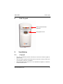
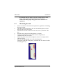
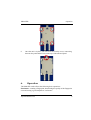
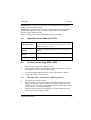
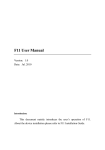
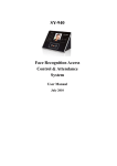
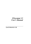
PRint-FPR
PRintX-FPR
User Manual
Synel Industries Ltd.
1
PRint-FPR
PRint-FPR 08/28/08
Part no.650445 (PRint-FPR-222-01)
This document has been prepared for PRint-FPR device. All rights reserved. Reproduction or use, without express permission of editorial or pictorial content, in any
manner is prohibited. No patent liability is assumed with respect to the use of the
information contained herein. While every precaution has been taken in the preparation of this manual, Synel Industries Ltd. assumes no responsibility for errors or
omissions. Neither is any liability assumed for damages resulting from the use of the
information contained herein. DCM and SY are trademarks of Synel Industries Ltd.
All trade names referenced herein are either trademarks or registered trademarks of
their respective companies.
Synel Industries Ltd.
2
PRint-FPR
1.
Introduction
Introduction
The PRint-FPR biometric controllers (with Optical sensor or Capacity
sensor) are part of the Synel series of access control portals. PRint-FPR units
combine fingerprint verification and identification.
PRint-FPR units work together with other units, according to the security
level required for the specific location of the unit. Working in conjunction
with other units defining parameters and maximizing security using
passwords defined by the user.
1.1
•
•
•
•
2.
•
•
•
•
•
•
•
Operation modes
Enroll - New fingerprint templates can be enrolled at the unit and stored
for future recognition.
Verification - The verification mode of access control requires a card/
code combination. The template is stored with reference to a card/code.
Up to 4000 card/code combinations and templates are stored. When an
employee swipes a card or keys-in a code, the unit checks whether the
card/code number exists, if it does the unit also checks the template
assigned to that number.
Identification - The identification mode does not require a card/code
combination. Up to 9090 fingerprint templates are stored in the terminal’s memory. When an employee places a finger on the sensor, the FP
(fingerprint) unit polls all existing templates for a match and confirms or
rejects access accordingly.
Erase - Deletes one or all stored templates from the memory.
Package
PRintX FPR unit
PRintX FPR mounting panel
RJ-11 Connection box with 5V power input
RJ-45 Connection box
A mounting set that includes the following:
2 screws for mounting the mounting panel
1 screw for securing the unit to mounting panel
Wall anchors:2 Brick + 2 Plaster
Mounting template
User manual on CD
Synel Industries Ltd.
3
PRint-FPR
Specifications
Recommended: PRintX-40 Power supply adaptor:12 to 15 Vdc,
max @ 880 mA
3.
Specifications
3.1
Technical Specifications
•
•
•
•
•
•
3.2
•
•
•
•
•
•
Dimensions: 15.5 x 7 x 6.1 cm
Weight: 350g
Operating temperature: -10 to +50°C
Relative humidity: 95%
Power supply: 5Vdc, 20.5A
Output relay rating: 24 V @ 3 A
General characteristics
Allow finger rotation +/- 18°
Allow displacement +/- 5 mm
False acceptance ratio up to 0.001
Equal error rate 0.001
Verification name <1 s
Enrolment time <5 s
Synel Industries Ltd.
4
PRint-FPR
4.
Unit Layout
Unit Layout
LED Operation Status
Indicator
Fingerprint sensor
5.
5.1
•
•
•
Installation
General
The unit is installed at sensitive locations to assess user entrance rights to
secure areas.
The unit works together with other units to increase security of the sensitive locations, where it is installed.
The back panel of the unit serves as an installation template, to mark the
location of the screws.
Synel Industries Ltd.
5
PRint-FPR
5.2
Installation
Finding the best location for the unit
Follow the guidelines below to find the best place to mount the terminal:
• Place the terminal by an easily accessible power outlet.
• Do not place the communication cable near a source of electromagnetic
radiation or radio interference such as power lines, large machinery, etc.
• Do not place terminal where exposed to extreme hat or cold, water, steam,
violent vibrations or strong electromagnetic radiation including high
voltage power lines and electrical equipment.
• The installation location selected should be as far as possible from sources
of electrical reference such as power equipment, computers, motors,
pumps, etc.
• Maintain at least a one meter distance from computer displays.
• Keep the cable by at least 30 cm away from any other cable.
• Use a power adaptor dedicated to the proximity unit. Make sure the
adapter carries a safety recognition marking such as UL, CSA or CE.
• Use a linear power supplier and not a switching power supplier which
generates an electro-magnetic field that shortens the reading range.
It is advisable to connect an independent power supplier to the reader.
• Make sure there are no metallic materials surrounding the unit.
• When mounting on a drywall (gypsum wall), make sure that there are no
rear metallic reinforcements to the wall.
• Make sure that it is safe to drill into the wall at the desired location.
• The terminal should be mounted at employee eye-height. Consider
accessibility of handicap users, if necessary. The standard recommended
height is 140cm (4’7”).
• Place the reader so that the user will be fully facing it when swiping the
badge since this is the best swiping position.
Caution: The terminal contains computer components. Thus should not
Synel Industries Ltd.
6
PRint-FPR
Installation
be mounted where it will be exposed to extreme heat or cold,
water, steam, violent vibrations, high electromagnetic
radiation including high voltage power lines and electrical
equipment.
5.3
1.
2.
3.
4.
5.
6.
7.
Mounting the unit
Select a location for the terminal using the above guidelines for finding
the best location:
Hold the mounting template to the wall and mark the places to drill
holes for the screws and cables.
Drill the holes for the connection cable and screws (with 6mm. drill
bit).
Inset the screw anchors for either plaster or concrete.
Connect communication cable from external components to
communication box as needed.
Mount the panel to the wall and adjust it so that it is straight and the
cable is in place.
Slide the unit downward onto to the mounting panel.
The hinges at the side of the panel (1) should slide into the track of the
mounting panel (2).
1
Synel Industries Ltd.
7
PRint-FPR
Operation
2
8.
6.
Once the unit is in place you can screw the security screw, connecting
between the panel and the unit, at the top of the unit and panel.
Operation
The PRintX/P reader allows the following basic operations:
Enrolment - scanning a fingerprint, determining the quality of the fingerprint
scan and storing a good template as a reference.
Synel Industries Ltd.
8
PRint-FPR
Operation
Identification - compares the currently scanned fingerprint to fingerprint
templates stored in the database.
Verification - proofing of the currently scanned fingerprint against stored
fingerprint templates for that user and an entered code or card. PRintX,
interacts with a PRintX-40 unit.
Erase - deleting one or all stored templates from the memory.
6.1
Operation Status Indicator LED
Flashing orange
A flashing orange LED indicates that the employee is
requested to place a finger for sampling purposes, while
the Enrolment process is on.
Orange
Waiting for fingerprint validation, while performing verification.
Green
Successful operation.
Red
Failure.
6.2
1.
2.
Access Control using PRint-FPR
Place the user-finger on the PRintX sensor.
A fingerprint recognised as matching a fingerprint template stored in
the unit allows access - activates door relay.
An un-recognised fingerprint denies access and initiates a buzzer
sound - door relay is not activated.
6.2.1
1.
2.
3.
FPU operation - Instructions and Best practices
Do not use your thumb to enrol.
Place the higher joint of your finger on the ridge lock and lower your
finger onto the sensor surface (make sure all other fingers are held
straight to avoid creating an angle between the enrolled finger and the
sensor surface - incorrect positioning).
Touch the sensor's plastic casing (black) in order to discharge static
electricity. Keep your finger steady!
Synel Industries Ltd.
9
PRint-FPR
4.
5.
6.
7.
8.
7.
Maintaining good working order
Press your finger gently onto the panel, avoid excessive pressure as it
will blur the print.
Make sure your finger is touching the sensor’s drive ring.
Use the same finger for enrolment as well as for verification.
If your finger is extremely dry, touch your forehead or the side of your
nose before placing it on the sensor.
Do not use a wet/moist finger for scanning.
Maintaining good working order
Do
•
You should always touch the conductive plastic before touching the
PRintX/P sensor in order to safely discharge any static electricity on your
skin or clothing.
Do not
•
•
•
•
Place the fingerprint sensor close to a heating source, such as a radiator
or hot plate
Spill any liquids on the sensor with the exception of isopropyl alcohol.
Subject the fingerprint sensor to heavy shocks or vibrations.
Allow the sensor to come in contact with metallic objects.
Synel Industries Ltd.
10