1
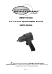
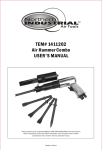
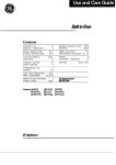
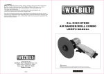
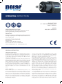
operating instructions
Product type
1/2” professional composite
impact wrench
operating instructions
Includes foreseen use, work stations, putting into service,
operating, dismantling, assembly and safety rules.
model
6100-0012 / 6100-1012
Important
Read these instructions carefully before installing, operating,
servicing or repairing this tool. Keep these instructions in a
safe accessible place.
manufacturer/supplier
Polar Tools ApS
Soldalen 9 · DK-7100 Vejle · Denmark
Tel: +45 7584 1122 · Fax: +45 6980 4374
E-mail: [email protected] · www.polartools.com
original instruction
Foreseen Use Of Tool
The impact wrench is designed for the tightening and loosening of
threaded fasteners within the range as specified by manufacturer. It
should only be used in conjunction with suitable impact type 1/2”
(13 mm) square female driver nut running sockets. Only use sockets
which are of the impact type.
It is allowed to use suitable extension bars, universal joints and socket
adaptors between the square output driver of the impact wrench and
the square female drive of the socket. Do not use the tool for any other
purpose than that specified without consulting the manufacturer or
the manufacturer’s authorized supplier. To do so may be dangerous.
Never use an impact wrench as hammer to dislodge or straighten cross
threaded fasteners. Never attempt to modify the tool for other uses
and never modify the tool for even its recommended use as a nut
runner.
Work Stations
The tool should only be used as a handheld hand operated tool. It is
always recommended that the tool is used when standing on the solid
floor. It can be in other positions but before any such use, the operator
must be in a secure position having a firm grip and footing and be
aware that when loosening fasteners the tool can move quite quickly
away from the fastener being undone. An allowance must always
be made for this rearward movement so as to avoid the possibility of
hand/arm/body entrapment.
1. Do not connect a quick connect coupling directly to the tool but
use a whip or a leader hose of say approximately 12 inches (300 mm)
length. Do not connect the tool to the airline system without incorporating an easy to reach and operate air shut off valve.
The air supply should be lubricated. It is strongly recommended that
an air filter, regulator, lubricator (FRL) is used as shown in Figure 1 as
this will supply clean, lubricated air at the correct pressure to the tool.
Details of such equipment can be obtained from your supplier. If such
equipment is nit used then the tool should be lubricated by shutting
off the air supply to the tool, depressurizing the line by pressing the
trigger on the tool. Disconnect the air line and pour into the intake
bushing a teaspoonful (5 ml) of a suitable pneumatic motor lubricating oil preferably incorporating a rust inhibitor. Reconnect tool to air
supply and run tool slowly for a few seconds to allow air to circulate
the oil. If tool is used frequently lubricate on daily basis and if tool
starts to slow or lose power. When lubricating, also ensure that screen
in intake bushing is clean.
It is recommended that the air pressure at the tool whilst the tool
is running at 90 psi/6.3 bar. The tool can run at lower and higher
pressure with the maximum permitted working air pressure of 100 psi/
7.0 bar. For a lower air pressure the tool will give a lower output for a
given setting of the sir regulator set for 90 psi/6.3bar. operation and
increased output for higher pressure. Hence it is possible that changes
in supply pressure can give situation where the fastener is under over
tightened. For changes in pressure, the regulator position and application should be reassessed. It is recommended that joint tightness of
the threaded fastener assembly be checked with suitable measuring
equipment. Follow the national legislation of waste disposal.
Putting Into Service
Air Supply
Use a clean lubricated air supply that will give a measured air pressure
at the tool of 90 psi/ 6.3 bar when the tool is running with the trigger
fully depressed And the air regulator in its maximum opening flow
position. Use recommended hose size and length. It is recommended
that the tool is connected to the air supply as shown in figure 1.
Safe Rules When Using an Impact Wrench
Read all these safety instructions before operating this product and
save these instructions.
The tool has been manufactured in conformity with the instruction
of EU machine directive. The EU mark will be considered void in the
event of inexpert repairs, the use of non-original parts and in case of
non-observance of the safety instructions in the user’s manual.
General safety rules:
1.
2.
3.
4.
FIGURE 1.
Take air from top
All pipe and fitting
should be 1/2” or larger
5.
Compressor with sufficient
capacity to maintain
recommended working
pressure at each tool outlet
Low spot
to trap
water
Easy to reach and
operate shut off valve
Air tool
Air regulator set at
recommended working
air pressure
Receiver tank
40 gallons or more
Drain daily
Filter lubricator
6.
7.
8.
Drain daily
Recommended air supply system
Operating
The output of the impact wrench in prime working condition is governed by mainly three factors
a)The input air pressure
b)The time the impact wrench is operated on joint.
Normal time for joints of average tension requirement 3 to 5 seconds.
c)The setting of air regulator for a given joint at a given pressure
operated for a given time.
The air regulator can be used to the regulate the output of the impact
wrench if no other control means is available. It is strongly recommended that an external pressure regulator ideally as part of a fitter/
regulator/lubricator (FRL) is used to control air inlet pressure so that the
pressure can be set to help control the tension required to be applied
to the threaded fastener joint.
There is no consistent reliable torque adjustment on an impact wrench
of this type. However, the air regulator can be used to adjust torque to
the approximate tightness of known threaded joint. To set the tool to
the desired torque, select an nut or screw of known tightness of the
same size, thread pitch and thread condition as those on the job. Turn
air regulator to low position, apply wrench to nut and gradually increase power (turn regulator to admit more air) until nut moves slightly in
the direction it was originally set. The tool is now set to duplicate that
tightness, note regulator setting for future use. When tightness nuts
not requiring critical torque values, run nut up flush and then tighten
an additional one-quarter to one-half turn(slight additional turning is
necessary if gaskets are being clamped). For additional power needed
on disassembly work, turn regulator to its fully open position. This
impact wrench is rated a bolt size(please refer technical specification
of tool). Rating must be down graded for spring U bolts, tie bolts,
long cap screws, double depth nuts badly rusted conditions and spring
fasteners as they absorb much of the impact power. When possible,
clamp or wedge the bolt to prevent spring back.
Soak rusted nuts in penetrating oil and break rust seal before removing with impact wrench. If nut does not start to move in three to five
seconds use a large size impact wrench. Do not use impact wrench
beyond rated capacity as this will drastically reduce tool life.
Note: Actual torque on a fastener is directly related to joint hardness,
tool speed, condition of socket and the time the tool is allowed to
impact.
Use the simplest possible tool=to-socket hook up. Every connection
absorbs energy and reduces power.
9.
10.
11.
12.
13.
14.
15.
16.
17.
18.
19.
20.
21.
22.
23.
24.
25.
26.
Watch the tool at all times when in use.
People under the influence of alcohol or drugs are not allowed to
use, repair or maintain the tools.
Keep unqualified persons, children, etc. away from the tool.
Keep work area clean and with sufficient daylight or artificial
lighting. The work area on which the machine is used must be
cleaned up. Disorder is potential cause of accidents.
Danger of explosion. Never use oxygen and combustible gas as an
air supply for the tool which many be ignited by spark and cause
fire or explosion.
Never use gasoline or other flammable liquids to clean the tool.
Do not use air tools in potentially explosive atmospheres such as
in the presence of flammable liquids, cleaning solvents, fluid energy or stored gases.
Do not expose air tools to rain. Do not use air tools in damp or
wet locations.
When a fault or failure is detected, the tool must immediately be
disconnected from the air supply and returned for repair.
It is not permitted to modify the tool in any way.
When not in use, keep tools in a dry place, either locked up or i a
high place, out of the reach of children.
Do not force small air tools to do the job of a heavy-duty task. Do
not use air tool for purpose of which was not intended.
Wear suitable ear protection at environment noise level>80db(A)
and safety spectacles when using the tool. Always wear approved
safety goggles if work in dusty. This also applies to other persons
in the near by vicinity.
Do not wear loose clothing or jewelry. They can be caught in
moving parts. Rubber gloves and non-skid foot wear are recommended when working outdoors. Wear protecti8ve hair covering
to contain long hair.
Keep proper footing and balance at all times.
Use clamps or a vice to hold work-piece. It is safer than using your
hand and free both hands to operate the air tool.
When not use, before performing service or changing accessories
please disconnect tool from air compressor.
Do not carry plugged in air tool with your finger on the switch
trigger. Be sure switch is in the “OFF” position when connecting
to air supply.
Watch what you are doing. Use common sense, even unsafe
situation or unbalanced positions, particularly when you are tired.
Air powered tools can vibrate in use. Vibration, repetitive motions or uncomfortable positions may be harmful to your hands or
arms. Stop using any tool if discomfort, tingling feeling or pain
occurs. Seek medical advice before resuming use.
For multiple hazards, read and understand the safety instructions
before installing, operating, repairing, maintaining, changing accessories on, or working near the assembly power tool for threaded fasteners. Failure to do so can result in serious bodily injury.
Only qualified and trained operators should install, adjust or use
the assembly power tool for threaded fasteners.
Do not modify this assembly power tool for threaded fasteners.
Modifications can reduce the effectiveness of safety measures
and increase the risks to the operator.
Do not discard the safety instructions; give them to the operator.
Do not use the assembly power tool for threaded fasteners if it
has been damaged.
Tools shall be inspected periodically to verify that the ratings and
markings required by this part of EN ISO 11148 are legibly marked
on the tool. The employer/user shall contact the manufacturer to
obtain replacement marking labels when necessary.
Safety precautions for projectile hazards
1.
2.
3.
Failure of the workpiece, of accessories or even of the inserted
tool itself can generate high-velocity projectiles.
Always wear impact-resistant eye protection during the operation
of the assembly power tool for threaded fasteners. The grade of
protection required should be assessed for each use.
Ensure that the workpiece is securely fixed
Safety precautions for entanglement hazard
1.
Entanglement hazards can result in choking, scalping and/or
lacerations if loose clothing, personal jewelry, neckwear, hair or
gloves are not kept away from the tool and accessories.
2. Gloves can be become entangled with the rotating drive, causing
severed or broken fingers.
3. Rotating drive sockets and drive extensions can easily entangle
rubber-coated or metal-reinforced gloves.
4. Do not wear loose-fitting gloves or gloves with cut or frayed fingers.
5. Never hold the drive, socket or drive extension.
6. Keep hands sway from rotating drives.
Safety precautions for operating hazards
1.
The use of the tool can expose the operator’s hands to hazards
including crushing, impacts, cuts and abrasions and heat. Wear
suitable gloves to protect hands.
2. Operators and maintenance personnel shall be physically able to
handle the bulk, weight and power of the tool.
3. Hold the tool correctly: be ready to counteract normal or sudden
movements and have both hands available.
4. Maintain a balanced body position and secure footing.
5. Release the start-and-stop device in the case of an interruption of
the energy supply.
6. Use only lubricants recommended by the manufacturer.
7. Do not use in confined spaces and beware of crushing hands between tool and workpiece, especially when unscrewing.
Safety precautions for
repetitive motions hazards
1.
2.
3.
When using a power tool for, the operator can experience discomfort in the hands, arms, shoulders, neck, or other parts of
the body.
While using an assembly power tool for threaded fasteners, the
operator should adopt a comfortable posture whilst maintaining
secure footing and avoiding awkward or off-balanced postures.
The operator should change posture during extended tasks,
which can help avoid discomfort and fatigue.
If the operator experiences symptoms such as persistent or recurring discomfort, pain, throbbing, aching, tingling, numbness,
burning sensations or stiffness, these warning signs should not
be ignored. The operator should tell the employer and consult a
qualified health professional.
Safety precautions for accessory hazards
Disconnect the assembly power tool for threaded fasteners
from the energy supply before changing the inserted tool or
accessory.
2. Do not touch sockets or accessories during impacting, as this
increases the risk of cuts, burns or vibration injuries.
3. Use only sizes and types of accessories and consumables that are
recommended by the assembly power tool for threaded fasteners
manufacturer.
4. Use only impact-wrench-rated sockets in good condition, as
poor condition or hand sockets and accessories used with impact
wrenches can shatter and become a projectile.
3.
The assembly power tool for threaded fasteners is not intended
for use in potentially explosive atmospheres and is not insulated
against coming into contact with electric power.
4. Make sure there are no electrical cables, gas pipes, etc., that can
cause a hazard if damaged by use of the tool
Safety precautions for dust
and fume hazards
1.
Dust and fumes generated when using assembly power tools for
threaded fasteners can cause ill health ( for example, cancer, birth
defects, asthma and/or dermatitis); risk assessment and implementation of appropriate controls for these hazards are essential.
2. Risk assessment should include dust created by the use of the tool
and the potential for disturbing existing dust.
3. Direct the exhaust so as to minimize disturbance of dust in a
dust-filled environment.
4. Where dust or fumes are created, the priority shall be to control
them at the point of emission.
5. All integral features or accessories for the collection, extraction or
suppression of airborne dust or fumes should be correctly used
and maintained in accordance with the manufacturer’s instructions.
6. Use respiratory protection in accordance with employer’s instructions and as required by occupational health and safety regulations
Safety precautions for noise hazards
1.
Unprotected exposure to high noise levels can cause permanent, disabling hearing loss and other problems, such as tinnitus
(ringing, bussing, whistling or humming in the ears).
2. Risk assessment and implementation of appropriate controls for
these hazards are essential.
3. Appropriate controls to reduce the risk may include actions such
as damping materials to prevent workpieces from “ringing”.
4. Use hearing protection in accordance with employer’s instructions
and as required by occupational health and safety regulations.
5. Operate and maintain the assembly power tool for threaded fasteners as recommended in the instruction handbook, to prevent
an unnecessary increase in noise levels.
6. If the assembly power tool for threaded fasteners has a silencer,
always ensure it is in place and in good working order when the
assembly power tool for threaded fasteners is operating.
7. Select, maintain and replace the consumable/inserted tool as recommended in the instruction handbook, to prevent an unnecessary increase in noise.
Safety precautions for
vibration hazards
1.
2.
3.
1.
Safety precautions for workplace hazards
1.
2.
Slips, trips and falls are major causes of workplace injury. Be
aware of slippery surfaces caused by the use of the tool and also
of trip hazards caused by the air line or hydraulic hose.
Proceed with care in unfamiliar surroundings. Hidden hazards,
such as electricity or other utility lines, can exist.
4.
5.
6.
7.
8.
9.
10.
Exposure to vibration can cause disabling damage to the nerves
and blood supply of the hands and arms.
Keep the hands away from the sockets.
Wear warm clothing when working in cold conditions and keep
your hands warm and dry.
If you experience numbness, tingling, pain or whitening of the
skin in your fingers or hands, stop using the assembly power tool
for threaded fasteners, tell your employer and consult a physician.
Operate and maintain the assembly power tool for threaded
fasteners as recommended in the instruction handbook, to
prevent an unnecessary increase in vibration levels.
Do not use worn or ill-fitting sockets or extensions, as this is likely
to cause a substantial increase in vibration.
Select, maintain and replace the consumable/inserted tool as
recommended in the instruction handbook, to prevent an unnecessary increase in vibration levels.
Sleeve fittings should be used where practicable.
Support the weight of the tool in a stand, tensioner or balancer,
if possible.
Hold the tool with a light but safe grip, taking account of the
required hand reaction forces, because the risk from vibration is
generally greater when the grip force is higher.
Additional safety instructions
for pneumatic power tools
1.
Always shut of air supply, drain hose of air pressure and disconnect tool from air supply when not in use, before changing accessories or when making repairs.
2. Never direct air at yourself or anyone else.
3. Whipping hoses can cause severe injury. Always check for damaged or loose hoses and fittings.
4. Cold air shall be directed away from the hands.
5. Do not use quick-disconnect couplings at tool inlet for impact and
air-hydraulic impulse wrenches. Use hardened steel (or material
with comparable shock resistance) threaded hose fittings.
6. Whenever universal twist couplings (claw couplings) are used,
lock pins shall be installed and whip check safety cables shall be
used to safeguard against possible hose-to-tool and hose-and
hose connection failure.
7. Do not exceed the maximum air pressure stated on the tool.
8. For torque-control and continuous-rotation tools, the air pressure
has a safety critical effect on performance. Therefore, requirements for length and diameter of the hose shall be specified.
9. Never carry an air tool by the hose.
Warning
1.
The tool shall not be used in explosive atmospheres unless specially designed for that purpose.
2. The tool is not electrically insulated. Do not use where there is a
possibility of coming into contact with live electricity.
3. Unexpected tool movement due to reaction forces or breakage of
inserted tool or reaction bar may cause injuries.
4. Preferably shut off the air supply before changing socket or at
least ensure that the hands are well clear of the operating trigger.
5. Be aware of the risk of crushing by torque between a reaction bar
and the workplace.
6. When loosening fasteners first ensure that there is sufficient clearance behind the tool to avoid hand entrapment. The tool will
move away from the threaded joint as the nut/bolt etc. is loosened and rides up the thread moving the tool with it.
7.
There is a risk of being injured specially when unscrewing in confined work place if hands are not kept away from the reaction bar.
Keep hands sway from the nut runner socket.
8. In case of nut runner socket failure, it may danger to person from
high speed splinters being emitted fro impact wrench.
9. Be aware of the whipping compressed air hose.
10. Always ensure that the reverse valves is in the correct position
before operating the tool. Do not run the tool unless the socket is
first located on the joint.
11. Prevent the loose clothes, long hair, or any other personal accessories from closing to the moving part to reduce the risk of being
caught trapped or drawn in the rotating spindle.
Maintenance instruction
1.
2.
3.
Dry the filter and the air inlet of the tool.
Lubricate the quick connect coupling to prevent blocking.
Air tool require lubrication throughout the life of the tool. The air
motor and bearing uses compressed air to start the tool. The moisture in compressed air will rust the air motor; you must lubricate
the motor daily.
4. Avoid storing the tool in a location subject to high humidity. If
the tool is left as it is used, the residual moisture inside the tool
can cause rust.
5. Before storage, lubricate tool and run it for a few seconds.
6. Regular inspection of spindles, threads, and clamping devices in
respect of wear and tolerances for location of abrasive products.
7. If the tool is too seriously damage to be used anymore, recycle
raw material instead of disposing as waste. The machine, accessories and packaging should be sorted for environmental-friendly
recycling. Check with your local authority or retailer for recycling
advice.
EC declaration of conformity
WE:
Polar Tools ApS
Soldalen 9, DK-7100 Vejle, Denmark
Declare in sole responsibility that the equipment
Equipment: Air Impact Wrench
Read the operator’s instructions
before operating the tool.
Model/Serial No.: 6100-0012 / 6100-1012
to which this declaration applies, complies with these
normative documents:
Machinery Directive:2006/42/EC
Wear eye protection device.
and conforms to the following EN standards,
EN ISO 12100:2010
EN ISO 11148-6:2010
Authorized representative established within the EU(if applicable):
Company Name:
Polar Tools Aps
Wear ear protection device.
Company Address: Soldalen 9, DK-7100 Vejle, Denmark
Person responsible for compiling the technical file established within the EU:
Name, Surname:
Mikael Linde
Address:
Jens Grøns Vej 1, DK-7100 Vejle, Denmark
Note: This declaration becomes invalid, if technical or operational modifications are
introduced without the manufacturers consent.
Name and Signature/Position Title
Mikael Linde, Owner
Date and place
Denmark, December 12, 2012
6100-0012 1/2” stubby composite impact wrench
6100-0012 ½” Stubby Composite Impact Wrench
PARTS NO.DescriptionQ’ty
Technical specification
PARTS NO.
DESCRIPTION
Q'TY
PARTS NO.
DESCRIPTION
impact wrench
product type
0985TA01
Oil Seal1/2” stubby professional
1 composite
0985TA23
Rear Cover
0985TA02
Regulator Knob
1
0985TA24
Screw
0985TA03
Hammer Case
1
0985TA25 level:
O-Ring 9.69 m/sec2
vibration
MODEL: 6100-0012
0985TA04
Bushing
1
0985TA26
Steel Ball
Measurement
0985TA05
Anvil Collar
1
0985TA27
Spring
K = 1.5 m/sec2
uncertainty:
9000
±
10%
RPM
(r/min):
0985TA06
O-Ring
1
0985TA28
Reverse Valve
0985TA07
Anvil (1/2" DR)
1
0985TA29
Triggerwith
Tested
in accordance
0985TA08
Hammer
Pin
2
0985TA30
O-Ring
EN
ISO
28927-2
WEIGHT: 1.30 kg 2.87 lbs
0985TA09
Hammer Dog
2
0985TA31
Muffler
0985TA10
Hammer Cage
1
0985TA32
Retainer
AIR PRESSURE: 6.3 bar (90 PSI)
other data:
0985TA11
Front Gasket
1
0985TA33
Valve Stem
air
inlet
1/4” (6.3 mm)
0985TA12
Motor Housing
1
0985TA34
Spring
bolt capacity
1/2” Deflector
recommended
maximum
0985TA13
O-Ring
1
0985TA35
Exhaust
30 ft / 10 m
13 mm
hose length:
0985TA14
Washer
1
0985TA36
O-Ring
torque
450 ft. lb
0985TA15
Ball Bearing
1
0985TA37
Washer
62 kg/m
0985TA16
Cylinder
1
0985TA38A
Hose Adaptor -18NPT
recommended
minimum
610 Nm
3/8” / 10 mm
hose bore Spring
diameter:
0985TA17
Pin
1
0985TA38B
Hose Adaptor -19PT
average air
4.2 cfm
0985TA18
Rotor Blade
6
0985TA38C
Hose Adaptor
-19PF(BSP)
consumption
0.12 m3/min
0985TA19
Rotor
1
Noise level:
LOADNO LOAD
overall length
4.81” (122 mm)
0985TA20
Rear Plate
1
94.2
89.1 dB (A)
overall width
2.52” (64 mm)
SOUND pressure level
0985TA21
Ball Bearing105.2 100.1 dB1 (A)
overall height
7.80” (198 mm)
sound power level
0985TA22
Rear Gasket
1
square drive
1/2”
clutch type
Twin hammer
Measurement uncertainty: K = 3dB
Tested in accordance with EN ISO 15744
Recommended Personal Safety Equipment
P6100-0012-01 Oil Seal
1
P6100-0012-02 Regulator Knob
1
P6100-0012-03 Hammer Case
1
P6100-0012-04Bushing
1
P6100-0012-05 Anvil Collar
1
P6100-0012-06O-Ring
1
P6100-0012-07 Anvil (1/2” DR)
1
P6100-0012-08 Hammer Pin
2
P6100-0012-09 Hammer Dog
2
P6100-0012-10 Hammer Cage
1
P6100-0012-11 Front Gasket
1
P6100-0012-12Motor Housing
1
P6100-0012-13O-Ring
1
P6100-0012-14Washer
1
P6100-0012-15 Ball Bearing
1
P6100-0012-16Cylinder
1
P6100-0012-17 Spring Pin
1
P6100-0012-18 Rotor Blade
6
P6100-0012-19Rotor
1
Q'TY
P6100-0012-20 Rear Plate
1
P6100-0012-21 Ball Bearing
4
1P6100-0012-22 Rear Gasket
1P6100-0012-23 Rear Cover
1
P6100-0012-24Screw
1
1P6100-0012-25O-Ring
1P6100-0012-26 Steel Ball
1
P6100-0012-27Spring
1
1P6100-0012-28 Reverse Valve
1P6100-0012-29Trigger
1
P6100-0012-30O-Ring
1
1P6100-0012-31Muffler
P6100-0012-32Retainer
1
1
1
1
1
4
1
1
1
1
1
1
1
1
P6100-0012-33 Valve Stem
1
P6100-0012-34Spring
1
P6100-0012-35 Exhaust Deflector
1
P6100-0012-36O-Ring
1
P6100-0012-37Washer
1
P6100-0012-38A Hose Adaptor -18NPT
USE:
Safety glasses and ear protectors
P6100-0012-38B Hose Adaptor -19PT
P6100-0012-38CHose Adaptor -19PF(BSP)
1
6100-1012 1/2” composite impact wrench
6100-1012 ½” Composite Impact Wrench
PARTS NO.DescriptionQ’ty
PARTS NO.
DESCRIPTION
Technical specification
Q'TY
PARTS NO.
DESCRIPTION
1285TA01
Oil Seal
1
1285TA23A
Hose Adaptor -18NPT
1285TA02product
Hammer
Case
1
1285TA23B
type 1/2” professional composite impact wrenchHose Adaptor -19PT
1285TA03
Bushing
1
1285TA23C
Hose Adaptor -19PF(BSP)
1285TA04
Anvil Collar
1
1285TA24
Muffler
9.44 m/sec2
vibration level:
6100-1012
1285TA05MODEL:
O-Ring
1
1285TA25
Regulator Knob
1285TA06
Anvil
1
1285TA26
Trigger
Measurement
1285TA07RPM (r/min):
Hammer Cage
1
1285TA27
K = 1.5 m/sec2
uncertainty:O-Ring
6500 ± 10%
1285TA08
Hammer Pin
2
1285TA28
O-Ring
Tested in accordance with
1285TA09
Hammer Dog
2
1285TA29
Ball Bearing
EN ISO 28927-2
2.02 kg 4.45 lbs
1285TA10WEIGHT:
Washer
1
1285TA30
Oil Seal
1285TA11
Front Gasket
1
1285TA31
Cylinder
1285TA12AIR PRESSURE:
Motor Housing
1
1285TA32
other data:Spring Pin
6.3 bar (90 PSI)
1285TA13
O-Ring
1
1285TA33
Rotor
Blade
air inlet
1/4” (6.3 mm)
1285TA14recommended
Steel Ball maximum
1
1285TA34
Rotor
bolt capacity
5/8”
30 ft / 101 m
1285TA15hoseSpring
1285TA35
Rear16Plate
mm
length:
1285TA16
Reverse Valve
1
1285TA36
Ball
Bearing
torque
900 ft. lb
1285TA17
Retainer
1
1285TA37
Rear125
Gasket
kg/m
1285TA18recommended
Valve Stem minimum 3/8” / 10 mm
1
1285TA38
Rear1220
Cover
Nm
hose bore diameter:
1285TA19
Spring
1
1285TA39
Screw
average air
4.8 cfm
1285TA20
Exhaust Deflector
1
consumption
0.14 m3/min
Noise
level:
1285TA21
O-Ring
LOADNO LOAD 1
overall length
6.50” (165 mm)
1285TA22SOUNDWasher
96.1
91.6 1dB (A)
overall width
2.88” (73 mm)
pressure level
sound power level
107.1
102.6 dB (A)
Measurement uncertainty: K = 3dB
Tested in accordance with EN ISO 15744
Recommended Personal Safety Equipment
overall height
square drive
clutch type
8.27” (210 mm)
1/2”
Twin hammer
USE:
Safety glasses and ear protectors
P6100-1012-01
Oil Seal
1
P6100-1012-02
Hammer Case
1
P6100-1012-03Bushing
1
P6100-1012-04
1
Anvil Collar
P6100-1012-05O-Ring
1
P6100-1012-06Anvil
1
P6100-1012-07
Hammer Cage
1
P6100-1012-08
Hammer Pin
2
P6100-1012-09
Hammer Dog
2
P6100-1012-10Washer
1
P6100-1012-11
1
Front Gasket
P6100-1012-12Motor Housing
1
P6100-1012-13O-Ring
1
P6100-1012-14
1
Steel Ball
P6100-1012-15Spring
1
P6100-1012-16
1
Reverse Valve
P6100-1012-17Retainer
1
P6100-1012-18
1
Valve Stem
P6100-1012-19Spring
Q'TY
1
P6100-1012-20
1
Exhaust Deflector
1
P6100-1012-21O-Ring
1
P6100-1012-22Washer
1
P6100-1012-32
Spring Pin
1
P6100-1012-33
Rotor Blade
6
1
P6100-1012-23A
Hose Adaptor -18NPT
1
1
P6100-1012-23B
Hose Adaptor -19PT 1
1
P6100-1012-23C Hose Adaptor -19PF(BSP)
1
P6100-1012-24Muffler
1
1
1
P6100-1012-25
Regulator Knob
1
1
P6100-1012-26Trigger
1
1
P6100-1012-27O-Ring
1
6
1
P6100-1012-28O-Ring
1
1
P6100-1012-29 Ball Bearing
1
1
P6100-1012-30
Oil Seal
1
1
1
P6100-1012-31Cylinder
1
4
P6100-1012-34Rotor
1
P6100-1012-35
Rear Plate
1
P6100-1012-36
Ball Bearing
1
P6100-1012-37
Rear Gasket
1
P6100-1012-38
Rear Cover
1
P6100-1012-39Screw
4