1
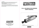
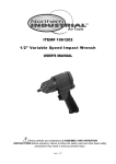
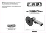
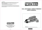
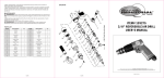
DIAGRAM
Air Tools
ITEM# 139273
AIR HAMMER KIT
USER'S MANUAL
PART LIST
Part#
Description
Qty.
Part#
Description
Qty.
1
Handle
1
10
Throttle Spring
1
2
Pin
2
11
Hose Adapter
1
3
Ball Seat
1
12
Upper Valve Case
1
4
O-ring
1
13
Valve Disc
1
5
Regulator
1
14
Lower Valve Case
1
6
Trigger
1
15
Piston
1
7
O-ring
1
16
Cylinder
1
8
Pin
1
17
Quick Change Retainer
1
9
Pin Seat
1
Read carefully and understand all ASSEMBLY AND OPERATION INSTRUCTIONS before operating.
Failure to follow the safety rules and other basic safety precautions may result in serious personal injury.
Made in China
3 of 3
For technical questions and replacement parts, please call 1-800-222-5381.
OPERATION
Thank you very much for choosing a NORTHERN TOOL + EQUIPMENT CO. Inc., Product!
For future reference, please complete the owner's record below:
Model: _______________ Purchase Date: _______________
Save the receipt, warranty and these instructions. It is important that you read the entire
manual to become familiar with this product before using it.
SET UP
This machine is designed for certain applications only. Northern Tool + Equipment
strongly recommends that this machine is not modified and/or used for any application
other than that for which it was designed. If you have any questions relative to a particular
application, DO NOT use the machine until you have first contacted Northern Tool +
Equipment to determine if it can or should be performed on the product.
Before using this product, please read the following instructions carefully.
Fig. 1
1.You will need to prepare a 1/4" air connector (sold separately) to connect to the Air Inlet.
First, wrap the 1/4" air connector (not included) with pipe thread seal tape before
connecting to a Air Source Hose (not included).
2.Attach air hose to the Air Inlet on the Air Hammer. Note: If you are not using an
automatic oiler system, before operation, add a few drops of Pneumatic Tool Oil to the
airline connection. Add a few drops more after each hour of continual use.
3.Set the air pressure on your compressor to 90 PSI. Do not exceed the recommended air
pressure of 90 PSI.
4.Check the air connection for leaks.
5.Turn off the compressor and disconnect the air source hose in preparation to load bits
into the Air Hammer.
ASSEMBLY
TECHNICAL SPECIFICATIONS
Item
Description
Item
Blows per minute
4500 BPM
Air Consumption
Description
5 CFM
Shank Opening
3/4"
Air Inlet Diameter
1/4"- 18NPT
Air Hose Size
3/8"
Accessories
5 chisels, 1pc spring
SAVE THIS MANUAL
You will need this manual for the safety warnings and precautions, assembly, operating,
inspection, maintenance and cleaning procedures, parts list and assembly diagram. Keep
this manual and invoice in a safe and dry place for future reference.
WARNINGS AND SAFETY RULES
Note: Before connecting the air supply, make sure you are wearing safety goggles
and a full face mask, ear protection, and steel toe shoes.
WARNING Any spectators in the immediate area will need eye and ear
protection.
Beware of flying chips of wood, concrete, metal, or any other material being
chiseled.
1.Connect the air hose to the Air Inlet and turn on the compressor (not included).
2.Grip the Air Hammer with both hands firmly and put the chisel tip up against the
workpiece you wish to chip.
3.Gently squeeze the trigger and move slowly along the workpiece. Do not push
down on the tool; let it do the work. If it does not do the intended job to satisfaction,
examine your bit to see if it is worn or dull.
4.When you are finished, turn off the air supply, hold the Air Hammer a safe distance
away from yourself and others and squeeze the trigger to bleed off the remaining air.
Then, disconnect the air hose.
1.Keep work area clean. Cluttered areas invite injuries.
2.Observe work area conditions. Do not use machines or power tools in damp or wet
locations. Don't expose to rain. Keep work area well lighted. Do not use electrically
powered tools in the presence of flammable gases or liquids.
3.Keep bystanders, pets, untrained operators and children away. Children must
never be allowed in the work area. Do not let them handle machines, tools, extension
cords, or air hoses.
4.Store idle equipment. When not in use, tools must be stored in a dry location to inhibit
rust. Always lock up tools and keep out of reach of children.
5.Use the right tool for the job. Do not attempt to force a small tool or attachment to do
the work of a larger industrial tool. There are certain applications for which this tool was
designed. It will do the job better and more safely at the rate for which it was intended. Do
not modify this tool and do not use this tool for a purpose for which it was not intended.
6.Dress properly. Do not wear loose clothing or jewelry as they can be caught in moving
parts. Protective, electrically non-conductive clothes and non-skid footwear are
recommended when working. Wear restrictive hair covering to contain long hair. Always
wear steel toe shoes when operating the Air Hammer.
7.Use eye and ear protection. Always wear ANSI-approved impact safety goggles and
ear protection. Wear a full face shield when breaking up concrete.
8.Do not overreach. Keep proper footing and balance at all times. Do not reach over or
across running machines or air hoses.
9.Maintain tools with care. Keep tools clean for better and safer performance. Follow
instructions for lubricating and changing accessories. Inspect tool cords and air hoses
periodically and, if damaged, have them repaired by an authorized technician. The handle
must be kept clean, dry, and free from oil and grease at all times.
10.Disconnect air supply. Disconnect air hose when not in use.
11.Avoid unintentional starting. Be sure the trigger is not depressed when carrying the
Air Hammer.
2 of 3
1 of 3
WARNING Always disconnect from the air source before examining or
changing bits.
1.Select the appropriate Chisel Bit. With your thumb,
put counterclockwise pressure on the spring and
insert the shank of the chisel bit into the Cylinder.
Release the spring. Holding the Air Hammer firmly,
pull the chisel bit hard to make sure it locked into
place. See Fig. 2.
Fig. 2