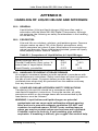
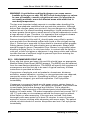
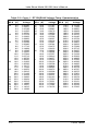
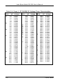
1
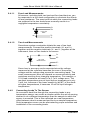
Lake Shore Model 201/208 User’s Manual 2.4.1.1 Four-Lead Measurements All sensors, including both two-lead and four-lead devices, can be measured in a four-lead configuration to eliminate the effects of lead resistance. The exact point at which the connecting leads are soldered to the two-lead sensor normally results in a negligible temperature uncertainty. I+ V+ Four-Lead Diode V I 2.4.1.2 Two-Lead Measurements Sometimes system constraints dictate the use of two-lead measurements. Connect the positive terminals (V+ and I+) together and the negative terminals (V– and I–) together at the instrument, then run two leads to the sensor. I+ Two-Lead Measurements V+ V I Some loss in accuracy can be expected since the voltage measured at the voltmeter becomes the sum of the sensor voltage and the voltage drop across the connecting leads. The exact measurement error will depend on sensor sensitivity and variations resulting from changing temperature. For example, a 10 ! lead resistance will result in a 0.1 mV voltage error. The resultant temperature error at liquid helium temperature is only 3 mK, but, because of the lower sensitivity (dV/dT) of the diode at higher temperatures, it becomes 10 mK at liquid nitrogen temperature. 2.4.2 2-4 Connecting Leads To The Sensor An excessive heat flow through the connecting leads to any temperature sensor can create a situation where the active sensing element is at a different temperature than the sample to which the sensor is mounted. This is then reflected as a real temperature offset between what is measured and the true sample temperature. Such temperature errors can be eliminated by proper selection and installation of the connecting leads. Installation