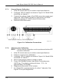
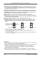
1
USER’S MANUAL Model 201 and 208 Digital Thermometer Includes Coverage For: Model 201 Single-Channel Thermometer Model 208 Eight-Channel Thermometer Lake Shore Cryotronics, Inc. 575 McCorkle Boulevard Westerville, Ohio 43082-8888 USA E-Mail Addresses: [email protected] [email protected] Visit Our Website: www.lakeshore.com Fax: (614) 891-1392 Telephone: (614) 891-2243 Methods and apparatus disclosed and described herein have been developed solely on company funds of Lake Shore Cryotronics, Inc. No government or other contractual support or relationship whatsoever has existed which in any way affects or mitigates proprietary rights of Lake Shore Cryotronics, Inc. in these developments. Methods and apparatus disclosed herein may be subject to U.S. Patents existing or applied for. Lake Shore Cryotronics, Inc. reserves the right to add, improve, modify, or withdraw functions, design modifications, or products at any time without notice. Lake Shore shall not be liable for errors contained herein or for incidental or consequential damages in connection with furnishing, performance, or use of this material. Rev. 1.0 P/N 119-018 4 November 1999 Lake Shore Model 201/208 User’s Manual LIMITED WARRANTY Lake Shore Cryotronics, Inc. (henceforth Lake Shore), the manufacturer, warrants this product for a period of 12 months from the date of shipment. During the warranty period, under authorized return of instruments or component parts to Lake Shore freight prepaid, the company will repair, or at its option replace, any part found to be defective in material or workmanship, without charge to the Owner for parts, service labor or associated customary shipping cost. Replacement or repaired parts will be warranted for only the unexpired portion of the original warranty. All products are thoroughly tested and calibrated to published specifications prior to shipment. Calibration Certifications are offered for 6 month periods only. Where such documentation must be updated, a re-certification service is offered by Lake Shore at a reasonable cost. LIMITATION OF WARRANTY This warranty is limited to Lake Shore products purchased and installed in the United States. This same protection will extend to any subsequent owner during the warranty period. It does not apply to damage caused by accident, misuse, fire, flood, or acts of God, from failure to properly install, operate, or maintain the product in accordance with the printed instructions provided. This warranty does not apply to defects resulting from improper or inadequate maintenance, unauthorized modification or misuse, operation outside of the environmental specifications for any product or part or buyer-supplied software interfacing. THIS WARRANTY IS IN LIEU OF ANY OTHER WARRANTIES, EXPRESSED OR IMPLIED, INCLUDING MERCHANTABILITY OR FITNESS FOR A PARTICULAR PURPOSE, WHICH ARE EXPRESSLY EXCLUDED. THE OWNER AGREES THAT LAKE SHORE’S LIABILITY WITH RESPECT TO THIS PRODUCT SHALL BE SET FORTH IN THIS WARRANTY, AND INCIDENTAL OR CONSEQUENTIAL DAMAGES ARE EXPRESSLY EXCLUDED. CERTIFICATION Lake Shore certifies that this product has been inspected and tested in accordance with its published specifications and that this product met its published specifications at the time of shipment. The accuracy and calibration of this product at the time of shipment are traceable to the United States National Institute of Standards and Technology (NIST); formerly known as the National Bureau of Standards (NBS), or to a recognized natural standard. TRADEMARK ACKNOWLEDGEMENT Manufacturers and sellers claim many designations as trademarks to distinguish their products. Where those designations appear in this manual and Lake Shore was aware of a trademark claim, the designations appear in initial capital letters with a ® ™ or symbol. ® Apiezon is a trademark of Biddle Instruments. ® Cryo-Gloves is a trademark of Tempshield. Duo-Twist™, Quad-Lead™, Quad-Twist™, and SoftCal™ are trademarks of Lake Shore Cryotronics, Inc. ® Teflon is a trademark of DuPont De Nemours. Copyright © 1993, 1995, 1997, and 1999 by Lake Shore Cryotronics, Inc. All rights reserved. No portion of this manual may be reproduced, stored in a retrieval system, or transmitted, in any form or by any means, electronic, mechanical, photocopying, recording, or otherwise, without the express written permission of Lake Shore. A Lake Shore Model 201/208 User’s Manual Declaration of Conformity We: Lake Shore Cryotronics, Inc. 575 McCorkle Blvd. Westerville, OH 43082-8888 Hereby declare that the equipment specified conforms to the following Directives and Standards. Application of Council Directives: 89/336/EEC Standards to which Conformity is Declared: EN55022-A EN50082-1 Type of Equipment: Model Number: ___________________________ Signature Digital Thermometer 201 or 208 _____________________ Date John M. Swartz President B Lake Shore Model 201/208 User’s Manual Manual Addendum on EMC for the Model 201 or 208 Electromagnetic Compatibility (EMC) of electronic equipment is a growing concern worldwide. Emissions of and immunity to electromagnetic interference is now part of most electronics design and manufacture. To qualify for the CE mark, the Model 201 or 208 meets the generic requirements of the European EMC directive 89/336/EEC as a Class A product. Class A products radiate more RF than Class B products and must include the following warning: WARNING: This is a Class A Product. In a domestic environment, this product may cause radio interference in which case the user may be required to take adequate measures. The instrument was tested under normal operating conditions with sensor and interface cables attached. If the installation and operating instructions in the User's Manual are followed there should be no degradation in EMC performance. Pay special attention to instrument cabling. Improperly installed cabling may defeat even the best EMC protection. For the best performance from any precision instrument, follow the grounding and shielding instructions in the User's Manual. In addition, the installer of the Model 201 or 208 should consider the following: • Leave no unused or unterminated cables attached to the instrument. • Make cable runs as short and direct as possible. • Do not tightly bundle cables that carry different types of signals. • Add the clamp-on ferrite filter (part number 109-053) included with the connector kit to the serial interface cable near the instrument rear panel when that interface is used. C Lake Shore Model 201/208 User’s Manual TABLE OF CONTENTS Chapter/Paragraph Title Page 1 INTRODUCTION..............................................................................1-1 1.0 General ..........................................................................1-1 1.1 System Description ........................................................1-1 1.2 Safety Summary.............................................................1-4 1.3 Safety Symbols ..............................................................1-5 2 INSTALLATION...............................................................................2-1 2.0 General ..........................................................................2-1 2.1 Inspection and Unpacking..............................................2-1 2.2 Repackaging For Shipment............................................2-1 2.3 Power and Ground Requirements..................................2-2 2.4 Sensor Installation Recommendations ..........................2-3 2.4.1 Two-Lead Vs. Four-Lead Measurements ...................2-3 2.4.1.1 Four-Lead Measurements.......................................2-4 2.4.1.2 Two-Lead Measurements .......................................2-4 2.4.2 Connecting Leads to the Sensor ................................2-4 2.4.3 Sensor Mounting ........................................................2-5 2.4.4 Measurement Errors Due To AC Noise ......................2-6 2.5 Sensor Input Connections..............................................2-7 2.6 Sensor Curve Definition .................................................2-9 2.7 Rack Mounting ...............................................................2-9 2.8 Initial Power Up Sequence...........................................2-11 2.9 Power Up Errors...........................................................2-11 3 OPERATION....................................................................................3-1 3.0 General ..........................................................................3-1 3.1 Units Key........................................................................3-1 3.2 Channel Key (Model 208 Only) ......................................3-1 3.3 Scan Mode .....................................................................3-1 3.4 Setting Dwell Times .......................................................3-2 3.5 Alarm Operation .............................................................3-3 3.5.1 Alarm Setpoint ............................................................3-3 3.5.2 Latched and Unlatched Alarms ..................................3-4 3.5.3 Alarm Fix Function (Model 208 Only) .........................3-4 3.6 SoftCal Compensations .................................................3-4 3.6.1 SoftCal Calibration......................................................3-5 3.6.2 Verifying SoftCal Operation ........................................3-6 3.6.3 Erasing SoftCal Compensations.................................3-6 Table of Contents i Lake Shore Model 201/208 User’s Manual TABLE OF CONTENTS (Continued) Chapter/Paragraph Title Page 4 REMOTE OPERATION................................................................... 4-1 4.0 General ......................................................................... 4-1 4.1 Serial Interface .............................................................. 4-1 4.1.1 Serial Interface Connections ..................................... 4-1 4.1.2 Serial Interface Operation.......................................... 4-3 4.1.3 Sample Basic Program .............................................. 4-4 4.1.4 Sample QuickBasic 4.0 Program............................... 4-4 4.2 Serial Interface Command Summary ............................ 4-5 5 SERVICE ........................................................................................ 5-1 5.0 General ......................................................................... 5-1 5.1 Model 201 Rear Panel Connections.............................. 5-1 5.2 Model 208 Rear Panel Connections.............................. 5-2 5.3 Error Code Troubleshooting .......................................... 5-3 5.4 General Maintenance .................................................... 5-4 5.5 Fuse Replacement ........................................................ 5-4 5.6 Line Voltage Configuration............................................ 5-4 5.7 Recalibration ................................................................. 5-5 5.7.1 Current Source Calibration ........................................ 5-6 5.7.2 A/D Converter Calibration.......................................... 5-6 5.8 Serial Interface Cable and Adapters ............................. 5-7 6 OPTIONS AND ACCESSORIES .................................................... 6-1 6.0 General ......................................................................... 6-1 6.1 Models........................................................................... 6-1 6.2 Accessories................................................................... 6-1 6.3 Wires ............................................................................. 6-3 6.4 Sensors ......................................................................... 6-3 APPENDIX A – GLOSSARY OF TERMINOLOGY ................................ A-1 APPENDIX B – HANDLING OF LHe & LN2.......................................... B-1 B1.0 General ......................................................................... B-1 B2.0 Properties ...................................................................... B-1 B3.0 Handling Cryogenic Storage Dewars ............................ B-1 B4.0 LHe and LN2 Safety Precautions .................................. B-1 B5.0 Recommended First Aid................................................ B-2 APPENDIX C – CURVE TABLES.......................................................... C-1 C1.0 General ......................................................................... C-1 ii Table of Contents Lake Shore Model 201/208 User’s Manual LIST OF ILLUSTRATIONS Figure No. 1-1 1-2 1-3 2-1 2-2 2-3 3-1 3-2 4-1 4-2 5-1 5-2 5-3 5-4 5-5 5-6 5-7 6-1 6-2 6-3 Title Page Model 201 Front Panel..............................................................1-2 Model 208 Front Panel..............................................................1-2 Model 2308-12 Case Physical Dimensions ............................1-10 Model 201 Sensor Connector J1 Details ..................................2-7 Model 208 Sensor Connector J1 Details ..................................2-8 Model 2090 Rack Mounting ....................................................2-10 Model 201 Front Panel..............................................................3-2 Model 208 Front Panel..............................................................3-2 Serial I/O (RJ-11) Connector Pin Definitions ............................4-2 Serial Interface Connections.....................................................4-2 Model 201 Rear Panel Connections .........................................5-1 Model 208 Rear Panel Connections .........................................5-2 Line Voltage Jumper Configuration ..........................................5-5 Calibration Connections............................................................5-6 Model 2001 RJ-11 Cable Assembly Wiring Details ..................5-7 Model 2002 RJ-11 to DB-25 Adapter Wiring Details ................5-7 Model 2003 RJ-11 to DB-9 Adapter Wiring Details ..................5-8 Model 2001 RJ-11 Cable Assembly..........................................6-4 Model 2002 RJ-11 to DB-25 Adapter........................................6-4 Model 2003 RJ-11 to DB-9 Adapter..........................................6-5 LIST OF TABLES Table No. 1-1 2-1 2-2 4-1 B-1 C-1 C-2 C-3 C-4 C-5 C-6 C-7 Title Page Model 201/208 Specifications ...................................................1-3 Line Voltage and Fuse Rating Selection...................................2-2 Model 201/208 Temperature Curves ........................................2-9 Serial Interface Specifications ..................................................4-1 Comparison of LHe to LN2 ....................................................... B-1 Curve 0 - DT-500DI-8B Voltage-Temp. Characteristics........... C-1 Curve 1 - DT-500DI-8A Voltage-Temp. Characteristics........... C-2 Curve 2 - DT-500DRC-D Voltage-Temp. Characteristics ........ C-3 Curve 3 - DT-500DRC-E1 Voltage-Temp. Characteristics....... C-4 Curve 4 - CTI Diode Voltage-Temp. Characteristics................ C-5 Curve 5 - DT-500DI-8C Voltage-Temp. Characteristics........... C-6 Curve 6 - DT-470 Voltage-Temp. Characteristics.................... C-7 Table of Contents iii Lake Shore Model 201/208 User’s Manual This Page Intentionally Left Blank iv Table of Contents Lake Shore Model 201/208 User’s Manual CHAPTER 1 INTRODUCTION 1.0 GENERAL This chapter provides an introduction to the Model 201/208 Digital Thermometer. The Model 201/208 was designed and manufactured in the United States of America by Lake Shore Cryotronics. A general description is provided in Paragraph 1.1, safety summary in Paragraph 1.2, and safety symbols in Paragraph 1.3. If you have just received your new Model 201/208, please proceed to Chapter 2 and become familiar with the installation instructions. Complete and detailed instrument and sensor operational information is contained in Chapter 3. Remote operation is outlined in Chapter 4. Limited service and rear panel connector definitions are contained in Chapter 5. Chapter 6 provides information on options and accessories. Appendix A is a Glossary of Terminology. Handling of Liquid Helium and Liquid Nitrogen is provided in Appendix B. Finally, details on sensor curves are provided in Appendix C. 1.1 GENERAL DESCRIPTION The Model 201/208 Digital Thermometers are ideal for monitoring critical temperature conditions in areas such as chemical investigation, materials research, superconductivity measurements, and in low temperature physics. The units feature: l Broad Temperature Range: 1.4 K to 475 K (–272 °C to 202 °C). l Single Channel (201) and Eight Channel (208) Models. l l For Use with Lake Shore DT-470 Series, DT-500 Series, and other Silicon Diode Sensors. System Accuracy (Instrument with Sensor) with SoftCal™ to within ±0.1 °C or better. l Displays Temperature in °C, °F, or K, or in Sensor Voltage. l High/Low Alarm Setpoint with Interfacing Alarm Contacts. l Standard RS-232C Output of Temperature, Input of Settings, and Alarm Status For Remote Operation. Introduction 1-1 Lake Shore Model 201/208 User’s Manual General Description (Continued) The Model 201 and 208 provide a usable temperature range not attainable in many other digital thermometers. Combined with Lake Shore DT-470 and DT-471 Series silicon diode temperature sensors, the digital thermometers provide repeatable, accurate measurements from nearly 0 Kelvin to well above room temperature. All Lake Shore DT-470 and DT-471 Series Sensors follow the same temperature response curve (Curve 10). Five bands of tracking accuracy are offered so that sensor selection can be made with both technical and economic considerations for a given application. The eight channel Model 208 features a user-programmable scan/dwell operation mode with dwell times of 0 (skip), 5, 10, 30 or 60 seconds. P-201-1-1.bmp Figure 1-1. Model 201 Front Panel P-201-1-2.bmp Figure 1-2. Model 208 Front Panel 1-2 Introduction Lake Shore Model 201/208 User’s Manual Table 1-1. Model 201/208 Specifications _________________________________________________________________________________________________________________________________________ Display: Four-digit LED display Resolution: 0.1 for values > 100 or < –100 0.01 for values between –100<T<100 Temperature Range: 1.4 K to 475 K without probe 23 K to 473 K with probe System Accuracy: To within ±0.1K in the range of 177 K to 313 K. To ±0.2 K or better over range of 30 K to 373 K. Above 373 K, accuracy will be ±1.0 K. Sensor Excitation: 10 µA constant current Repeatability: <50 mK Input Range: 0 to 3 volts with a resolution of 0.1 millivolts Hi/Lo Alarm Setpoint: 0.1° resolution Alarm Relay: Single SPDT relay, rated 28 VDC or Peak AC, 0.25 A (3 W max.) Scan/Dwell: The Model 208 automatically scans all eight channels with selectable dwell times of 0 (skip), 5, 10, 30 and 60 seconds for each channel. Connections: Sensor connection is 4-lead (2 current and 2 voltage) Response Curves*: Standard Curve 10 DT-500DI-8A (also -8B and -8C) DT-500DRC-D DT-500DRC-E1 CTI Curve C * SoftCal works only with DT-470/471 diode sensors. COMPUTER INTERFACE Type: RS-232C Serial 3-Wire (Refer to Table 4-1 for details.) MECHANICAL Ambient Temperature Range: 18 – 28 °C (64 – 82 °F), or 15 – 35 °C (59 – 95 °F) with reduced accuracy Power Requirements: 90 – 125 or 210 – 250 VAC, 50/60 Hz, 3 watts Dimensions: 41 mm High × 106 mm Wide × 164 mm Deep (1.6 inches × 4.2 inches × 6.5 inches) Weight: 0.5 kilogram (1.1 Pounds) NOTES: 1. Product specifications are subject to change without notice. 2. Electronic temperature accuracy of the system in a given temperature range is the sum of the specifications given for input and output. Sensor calibration errors are not included. _________________________________________________________________________________________________________________________________________ Introduction 1-3 Lake Shore Model 201/208 User’s Manual 1.2 SAFETY SUMMARY The following general safety precautions must be observed during all phases of operation, service, and repair of this instrument. Failure to comply with these precautions or with specific warnings elsewhere in this manual violates safety standards of design, manufacture, and intended use of the instrument. Lake Shore Cryotronics, Inc. assumes no liability for the customer's failure to comply with these requirements. Ground The Instrument To minimize shock hazard, the instrument chassis and cabinet must be connected to an electrical ground. The instrument is equipped with a three-conductor AC power cable. The power cable must either be plugged into an approved three-contact electrical outlet or used with a three-contact adapter with the grounding wire (green) firmly connected to an electrical ground (safety ground) at the power outlet. The power jack and mating plug of the power cable meet Underwriters Laboratories (UL) and International Electrotechnical Commission (IEC) safety standards. Do Not Operate In An Explosive Atmosphere Do not operate the instrument in the presence of flammable gases or fumes. Operation of any electrical instrument in such an environment constitutes a definite safety hazard. Keep Away From Live Circuits Operating personnel must not remove instrument covers. Component replacement and internal adjustments must be made by qualified maintenance personnel. Do not replace components with power cable connected. To avoid injuries, always disconnect power and discharge circuits before touching them. Do Not Substitute Parts Or Modify Instrument Because of the danger of introducing additional hazards, do not install substitute parts or perform any unauthorized modification to the instrument. Return the instrument to an authorized Lake Shore Cryotronics, Inc. representative for service and repair to ensure that safety features are maintained. 1-4 Introduction Lake Shore Model 201/208 User’s Manual 1.3 SAFETY SYMBOLS ! Product will be marked with this symbol in order to protect against damage to the instrument. Indicates dangerous voltage (terminals fed by voltage over 1000 volts must be so marked). or Protective conductor terminal. For protection against electrical shock in case of a fault. Used with field wiring terminals to indicate the terminal which must be connected to ground before operating equipment. Low-noise or noiseless, clean ground (earth) terminal. Used for a signal common, as well as providing protection against electrical shock in case of a fault. A terminal marked with this symbol must be connected to ground in the manner described in the installation (operating) manual, and before operating equipment. or Frame or chassis terminal. A connection to the frame (chassis) of the equipment which normally includes all exposed metal structures. Alternating current (power line). Direct current (power line). Alternating or direct current (power line). Introduction 1-5 Lake Shore Model 201/208 User’s Manual This Page Intentionally Left Blank 1-6 Introduction Lake Shore Model 201/208 User’s Manual CHAPTER 2 INSTALLATION 2.0 GENERAL This chapter provides installation instructions for the Model 201/208 Digital Thermometer. Inspection and unpacking instructions are provided in Paragraph 2.1, repackaging for shipment in Paragraph 2.2, sensor installation recommendations in Paragraph 2.3, power and ground requirements in Paragraph 2.4, sensor curve definitions in Paragraph 2.5, and rack mounting details in Paragraph 2.6. 2.1 INSPECTION AND UNPACKING Inspect shipping containers for external damage. Claims for damage (apparent or concealed) or partial loss of shipment must be made in writing to Lake Shore within 5 days from receipt of goods. If damage or loss is apparent, please notify the shipping agent immediately. Open the shipping container. A packing list is included with the instrument to simplify checking that the unit, sensor, accessories, and manual were received. Please use the packing list and the spaces provided to check off each item as the instrument is unpacked. Inspect for damage. Be sure to inventory all components supplied before discarding any shipping materials. If there is damage to the instrument in transit, be sure to file proper claims promptly with the carrier and insurance company. Please advise Lake Shore Cryotronics of such filings. In case of parts or accessory shortages, advise Lake Shore immediately. Lake Shore cannot be responsible for any missing parts unless notified within 60 days of shipment. 2.2 REPACKAGING FOR SHIPMENT If it is necessary to return the Model 201/208, sensors, or accessories for repair or replacement, a Return Goods Authorization (RGA) number must be obtained from a factory representative before returning the instrument to our service department. When returning an instrument for service, the following information must be provided before Lake Shore can attempt any repair. 1. 2. 3. 4. 5. Instrument model and serial number. User’s name, company, address, and phone number. Malfunction symptoms. Description of system. Returned Goods Authorization (RGA) number. If possible, the original packing material should be retained for reshipment. If not available, consult Lake Shore for shipping and packing instructions. Installation 2-1 Lake Shore Model 201/208 User’s Manual 2.3 POWER AND GROUND REQUIREMENTS The Model 201/208 requires a power source of 90 – 125 or 210 – 250 VAC, 50 or 60 Hz, single phase, 3 Watts. A three-prong detachable power cord for 120 VAC operation is included. Connect to rear panel UL/IEC/ICEE standard plug. The fuse rating is defined in Table 2-1. WARNING: To prevent electrical fire or shock hazards, do not expose this instrument to rain or excess moisture. CAUTION: Verify that the AC Line Voltage Selection Wheel located on the rear panel of the Model 201/208 is set to the available AC line voltage and that the proper fuse is installed before inserting the power cord and turning on the instrument. To change voltage configuration, refer to Chapter 5. NOTE: Do not attach the shield to earth ground at the sensor end or noise may be introduced at the measurement end. Table 2-1. Line Voltage and Fuse Rating Selection Select 115 Range 90 – 125 VAC Fuse 0.2 A (Slow Blow) 230 210 – 250 VAC 0.1 A (Slow Blow) To protect operating personnel, the National Electrical Manufacturer’s Association (NEMA) recommends, and some local codes require, instrument panels and cabinets be grounded. This instrument is equipped with a three-conductor power cable which, when plugged into an appropriate receptacle, grounds the instrument. Grounding and shielding of signal lines are major concerns when setting up any precision instrument or system. The 201/208 has included ground isolation of the sensor excitation to allow 4-wire measurement of diode voltage and resistance. Improper grounding of sensor leads and shields can defeat this feature. Digital logic in the Model 201/208 is tied directly to earth ground for interface communication. The low side of the heater output is directly connected to earth ground. Shield sensor cables whenever possible. Attach the shields to the shield pin provided in the connector. 2-2 Installation Lake Shore Model 201/208 User’s Manual 2.4 SENSOR INSTALLATION RECOMMENDATIONS Abbreviated diode sensor installation recommendations for the Model 201/208 are included in this paragraph. Please refer to the Lake Shore Product Catalog for installation details and sensor specifications. Call Lake Shore for copies of application notes or with questions or comments concerning sensor installation. The following are general recommendations on sensor installation: 1. Do not ground the sensor. 2. Shield the leads and connect the shield wire to SHIELD on the screw terminal connector only. Do not connect shield at the other end of the cable. 3. Keep leads as short as possible. 4. Use twisted-pair wire. Use of Lake Shore Duo-Twist™ wire (or equivalent) for two-wire, or Quad-Twist™ wire (or equivalent) for four-wire applications, is strongly recommended. 5. Lead wires should be thermally anchored. Paragraph 2.4.1 discusses two-lead versus four-lead measurements. Paragraph 2.4.2 discusses connecting leads. Sensor mounting is covered in Paragraph 2.4.3. Finally, Paragraph 2.4.4 describes the effect of measurement errors due to AC noise. 2.4.1 Two-Lead Versus Four-Lead Measurements In the two lead measurement scheme, the leads used to measure the sensor voltage are also the current carrying leads. The resultant voltage measured at the instrument is the sum of the temperature sensor voltage and the IR voltage drop within the two current leads. Since in a cryogenic environment, the flow of heat down the leads can be of critical concern, normally wire of small diameter and significant resistance per foot is preferred to minimize this heat flow. Consequently, a voltage drop within the leads can be present. In a four-lead measurement scheme, the current is confined to one pair of current leads with the sensor voltage measured using the remaining lead pair which is not carrying current. Installation 2-3 Lake Shore Model 201/208 User’s Manual 2.4.1.1 Four-Lead Measurements All sensors, including both two-lead and four-lead devices, can be measured in a four-lead configuration to eliminate the effects of lead resistance. The exact point at which the connecting leads are soldered to the two-lead sensor normally results in a negligible temperature uncertainty. I+ V+ Four-Lead Diode V I 2.4.1.2 Two-Lead Measurements Sometimes system constraints dictate the use of two-lead measurements. Connect the positive terminals (V+ and I+) together and the negative terminals (V– and I–) together at the instrument, then run two leads to the sensor. I+ Two-Lead Measurements V+ V I Some loss in accuracy can be expected since the voltage measured at the voltmeter becomes the sum of the sensor voltage and the voltage drop across the connecting leads. The exact measurement error will depend on sensor sensitivity and variations resulting from changing temperature. For example, a 10 ! lead resistance will result in a 0.1 mV voltage error. The resultant temperature error at liquid helium temperature is only 3 mK, but, because of the lower sensitivity (dV/dT) of the diode at higher temperatures, it becomes 10 mK at liquid nitrogen temperature. 2.4.2 2-4 Connecting Leads To The Sensor An excessive heat flow through the connecting leads to any temperature sensor can create a situation where the active sensing element is at a different temperature than the sample to which the sensor is mounted. This is then reflected as a real temperature offset between what is measured and the true sample temperature. Such temperature errors can be eliminated by proper selection and installation of the connecting leads. Installation Lake Shore Model 201/208 User’s Manual Connecting Leads To The Sensor (Continued) In order to minimize any heat flow through the leads, the leads should be of small diameter and low thermal conductivity. Phosphor-bronze or Manganin wire is commonly used in sizes 32 or 36 AWG. These wires have a fairly low thermal conductivity yet the electrical resistivities are not so large as to create any problems in measurements. Lead wires should also be thermally anchored at several temperatures between room temperature and cryogenic temperatures to guarantee that heat is not being conducted through the leads to the sensor. 2.4.3 Sensor Mounting Before installing a diode sensor, identify which lead is the anode and which is the cathode. When viewed with the base down and with the leads towards the observer, the positive lead (anode) is on the right and the negative lead (cathode) is on the left. The Lake Shore DT-470-SD silicon diode sensor lead configuration is shown below. For other sensors, read the accompanying literature or consult the manufacturer to ensure positive identification of sensor leads. Be sure the lead identification remains clear even after installation of the sensor. It is also a good idea to record the serial number and location of the sensor. DT-470-SD Diode Sensor Leads Cathode Anode On the DT-470-SD, the base is the largest flat surface. It is sapphire with gold metalization over a nickel buffer layer. The base is electrically isolated from the sensing element and leads, and all thermal contact to the sensor should be made through the base. A thin braze joint around the sides of the SD package is electrically connected to the sensing element. Contact to the sides with any electrically conductive material must be avoided. When installing the sensor, make sure there are no electrical shorts or current leakage paths between the leads or between the leads and ground. If IMI-7031 varnish or epoxy is used, it may soften varnish-type lead insulations so that high resistance shunts appear between wires if sufficient time for curing is not allowed. Installation 2-5 Lake Shore Model 201/208 User’s Manual Sensor Mounting (Continued) Teflon® spaghetti tubing is useful for sliding over bare leads when the possibility of shorting exists. Also, avoid putting stress on the device leads and allow for the thermal contractions that occur during cooling which could fracture a solder joint or lead if installed under tension at room temperature. For temporary mounting in cold temperature applications, a thin layer of Apiezon® N Grease should be used between the sensor and sample to enhance the thermal contact under slight pressure. The preferred method for mounting the DT-470-SD sensor is the Lake Shore CO Adapter. CAUTION: Lake Shore will not warranty replace any device damaged by a user-designed clamp or damaged by solder mounting. If semi-permanent mountings are desired, the use of Stycast epoxy can replace the use of Apiezon N Grease. NOTE: Do not apply Stycast epoxy over the DT-470-SD package. Stress on the sensor can cause shifts in the readings. In all cases, the mounting of the sensor should be periodically inspected to verify that good thermal contact to the mounting surface is maintained. 2.4.4 Measurement Errors Due To AC Noise Poorly shielded leads or improperly grounded measurement systems can introduce AC noise into the sensor leads. For diode sensors, the effect of the AC noise appears as a shift in the DC voltage measurement due to the non-linear current/voltage characteristics of the diode. When this occurs, the DC voltage measured will be too low and the corresponding temperature indication will be high. The resulting measurement error can approach several tenths of a kelvin. To determine if this is a problem in your measurement system, perform either of the two following procedures. 1. 2-6 Place a capacitor across the diode to shunt the induced AC currents. The size of the capacitor used will depend on the frequency of the noise. If the noise is related to the power line frequency, use a 10 µF capacitor. If AC-coupled digital noise is suspected (digital circuits or interfaces), then use a capacitor in the range of 0.1 to 1 µF. In either case, if the resultant DC voltage measured is observed to increase, there is induced noise in your measurement system. Installation Lake Shore Model 201/208 User’s Manual Measurement Errors Due To AC Noise (Continued) 2. Measure the AC voltage across the diode with an AC voltmeter or oscilloscope. Note that most voltmeters will not have the frequency response to measure noise associated with digital circuits or interfaces (which operate in the MHz range). A thorough discussion of this potential problem, and the magnitude of error which may result, is given in the paper “Measurement System-Induced Errors In Diode Thermometry,” J.K. Krause and B.C. Dodrill, Rev. Sci. Instr. 57 (4), 661, April, 1986; which is available from Lake Shore upon request. The potential for this type of error can be greatly reduced by connecting twisted leads (pairs) between the measurement instruments and the diode sensors when an AC noise environment exists. We recommend the use of Duo-Twist™ Cryogenic Wire, which features phosphor bronze wire, 32 or 36 AWG, twisted at 3.15 twists per centimeter (8 twists per inch). Duo-Twist wire is available from Lake Shore. Refer to the Lake Shore Product Catalog or contact Lake Shore for further information. 2.5 SENSOR INPUT CONNECTIONS The Model 201 has one rear panel 4-pin sensor input connector designated J1 INPUT 1. The connector pins, numbered 1 thru 4, are shown in Figure 2-1. J1 INPUT 1 4 1 3 2 C-201-2-1.eps Terminal Description 4 1 2 3 Case + Current Out – Current Out – Voltage Sense + Voltage Sense Shield Figure 2-1. Model 201 Sensor Connector J1 Details Installation 2-7 Lake Shore Model 201/208 User’s Manual Sensor Input Connections (Continued) The Model 208 has a 36-pin Miniature-D style connector designated J1 INPUTS for inputs 1 thru 8. A Model 208-D connector is included to solder interfacing connections to J1. The pin configuration of the Model 208-D is shown in Figure 2-2. 2 1 4 3 6 5 7 8 10 12 14 16 18 9 11 13 15 17 20 22 24 26 28 30 32 34 36 19 21 23 25 27 29 31 33 35 C-201-2-2.eps Terminal Description Input Terminal Description Input 1 2 3 4 5 6 7 8 9 10 11 12 13 14 15 16 17 18 +V –V +V –V +V –V +V –V +V –V +V –V +V –V +V –V Shield Shield 1 1 2 2 3 3 4 4 5 5 6 6 7 7 8 8 — — 19 20 21 22 23 24 25 26 27 28 29 30 31 32 33 34 35 36 +I –I +I –I +I –I +I –I +I –I +I –I +I –I +I –I Shield Shield 1 1 2 2 3 3 4 4 5 5 6 6 7 7 8 8 — — Figure 2-2. Model 208-D Sensor Connector Details 2-8 Installation Lake Shore Model 201/208 User’s Manual 2.6 SENSOR CURVE DEFINITION In order for the instrument to display accurate temperature, a response curve that matches the sensor being used must be selected. Seven standard curves are stored within the Model 201/208. Different curves may be assigned to each channel of the Model 208. The curves are numbered 0 through 6 and are detailed in Appendix C. The curve the unit is configured for is listed on the inside of the front cover. Curve 6 (DT-470 Curve 10) is the standard curve which will be selected unless specified differently upon ordering. To determine which curve is selected, press and hold the UNITS key and turn on (1) the rear panel SET switch (DIP switch 3). Release the UNITS key. The 201 will now display the curve number in the display window. The Model 208 will display the curve number in the display window and the channel number in the channel window. In order to display curves for the other channel numbers in the Model 208, simply press the CHANNEL key and scroll through the eight channels. To change the curve, press the UNITS key. The instrument will scroll through curves 0 through 6. In the Model 208, press the CHANNEL key to select additional channels for curve selection. Then, simply press the UNITS key to scroll through the curves. After the new curve is selected, turn the SET switch on the rear panel back off (0). The unit will now return to normal operation. Table 2-2. Model 201/208 Temperature Curves 2.7 Curve No. Range (K) 0 1 2 3 4 5 6 0 – 324.9 0 – 324.9 0 – 324.9 0 – 324.9 0 – 324.9 0 – 324.9 0 – 474.9 Description DT-500DI-8B DT-500DI-8A DT-500DRC-D DT-500TDC-E1 CTI Curve C DT-500DI-8C DT-470 Curve 10 RACK MOUNTING The Models 201 and 208 can be installed in a standard size ¼ panel EIA rack space. If you have ordered a 2090 rack mounting adapter, use the following instructions for installation. See Figure 2-3. 1. Remove the front feet on the bottom of the unit and attach the lower rack piece using the threaded holes with two of the four screws provided. 2. Locate the two mounting hole access covers on the top of the unit. Attach the other rack Installation 2-9 0.265 (6.73) 0.215 (5.46) A B A Hole Sizes: A = 0.189 (0.480) Diameter 4 Places B = 0.169 (0.429) Diameter 2 Places 1.50 (38.10) 2.50 (63.5) Lake Shore Model 201/208 User’s Manual 1.25 (31.75) Model 201 or 208 Front Panel A B 1.44 (35.58) C L A 1.44 (35.58) 4.18 (106.17) C-201-2-3.eps Figure 2-3. Model 2090 Rack Mounting 2-10 Installation Lake Shore Model 201/208 User’s Manual 2.8 2.9 INITIAL POWER UP SEQUENCE The following test sequence occurs at power up. 1. All display segments are lighted. 2. The unit displays “-201-201-” -208-.” -201- or “-208-208- 3. The instrument then begins normal operation. The Units selected will flash. Model 208s also indicate the selected channel. POWER UP ERRORS On power up, the 201/208 does a check of the internal memory. In the event that a problem exists, an error message will be displayed on the instrument's front panel. “Er01 Er01” Er01 on the display, indicates that there is a hardware problem in the instrument's memory. This error is not correctable by the user and the factory should be consulted. “Er02 Er02” Er02 on the display indicates that there is a soft error in the instrument's memory. This error can be corrected by closing dip switch 1 on the rear panel for at least 5 seconds. Then, put the switch in the open position. You must follow the calibration procedure described in Paragraph 5.3 after an error 2 has been reset. “OL OL” OL means overload, indicating the voltage input is too high. This can be caused by an open sensor or diode sensor wired backwards. Installation 2-11 Lake Shore Model 201/208 User’s Manual This Page Intentionally Left Blank 2-12 Installation Lake Shore Model 201/208 User’s Manual CHAPTER 3 OPERATION 3.0 GENERAL This chapter describes operation of the Model 201/208 Digital Thermometer. Units key operation is provided in Paragraph 3.1, Channel key (Model 208 only) in Paragraph 3.2, scan mode in Paragraph 3.3, setting dwell times in Paragraph 3.4, alarm operation in Paragraph 3.5, SoftCal compensations in Paragraph 3.6, calibration in Paragraph 3.7, verifying SoftCal operation in Paragraph 3.8, and erasing SoftCal compensations in Paragraph 3.9. 3.1 UNITS KEY The UNITS key selects the different units of measurement. The thermometer reads in voltage or temperature (kelvin, Celsius, or Fahrenheit). Press the UNITS key to scroll through the various selections. The UNITS key is also used to determine if the SoftCal feature is active. Press and hold the UNITS key for 3 seconds. If SoftCal is not active, "-000-000-" -000- will appear in the display. 3.2 CHANNEL KEY (MODEL 208 ONLY) This key scrolls through the eight possible sensor channels. The Channel key is also used to determine if Scan mode is activated. Press and hold 1 to 2 seconds to toggle the scan mode on or off. A red light will glow in the upper left channel display if the scan mode is active. 3.3 SCAN MODE The thermometer can scan 8 channels or monitor 1 channel. To enable scan mode, press the CHANNEL key for more than 1 but less than 2 seconds. If a light appears in the upper left of the channel display window, then the thermometer is in SCAN mode. If the light does not appear, the thermometer is in single-channel mode. CHANNEL key is a toggle. Repeat action to reverse mode. Operation 3-1 Lake Shore Model 201/208 User’s Manual 3.4 SETTING DWELL TIMES The time the thermometer pauses on each channel (dwell) can be set for 5, 10, 30, or 60 seconds. A dwell time of 0 instructs the thermometer to skip that particular channel. To set the dwell: 1. Hold the CHANNEL key 3 for seconds. Do not release. 2. After 3 seconds, while still pressing CHANNEL, use the UNITS key to select the desired time; 0 (skip), 5, 10, 30, or 60 seconds. 3. Repeat the procedure for each desired channel. The default channel dwell is 5 seconds. P-201-1-1.bmp Figure 3-1. Model 201 Front Panel P-201-1-2.bmp Figure 3-2. Model 208 Front Panel 3-2 Operation Lake Shore Model 201/208 User’s Manual 3.5 3.5.1 ALARM OPERATION Operation of the Model 201/208 alarm is detailed in the following paragraphs. Alarm setpoint is described in Paragraph 3.5.1, latched and unlatched alarms in Paragraph 3.5.2, and the alarm fix function (Model 208 only) in Paragraph 3.5.3. Alarm Setpoint The alarm setpoint is a temperature which activates the alarm relay. The alarm setpoint can be set to warn of temperatures rising above a certain point (high alarm), or falling below a certain point (low alarm). NOTE: Alarm setpoints work for temperatures, not voltage. If in voltage mode while setting an alarm setpoint, the thermometer will default to kelvin for the alarm setpoint. To display the alarm setpoint, move the SET switch on the rear panel to position 1. The setpoint will be indicated in the display. In order to change the setpoint: 1. Make sure the SET switch is in position 1. 2. Hold the UNITS key until the desired temperature is reached. UNITS is a toggle. If the UNITS key is released and pressed again, the temperature direction is reversed. When the temperature display is increasing, the alarm will be a high setpoint. If temperature display is decreasing, the alarm will be a low setpoint. 3. Release the UNITS key when the desired setpoint is reached. For a Model 208, press the CHANNEL key to set the alarm for each channel displayed in the channel window and repeat the steps above. Move the SET switch back to position 0. The alarm is now enabled. When it is triggered an alarm status light will appear in the upper left of the temperature display. The alarm can be connected to another device which will be triggered when the alarm is activated. The three contact terminal block is present on the rear panel as J3 ALARM. The alarm contacts are designated 1 COM 2 with 1 representing the normally open state and 2 representing the normally closed state. Operation 3-3 Lake Shore Model 201/208 User’s Manual 3.5.2 Latched And Unlatched Alarms Alarms can be either latched or unlatched. The alarm is latched when the LATCH switch is in position 1. The alarm will turn on when triggered by the alarm setpoint, but will not automatically turn off when the temperature drops below the high setpoint or rises above the low setpoint. The alarm is unlatched when the LATCH switch is in position 0. When unlatched, the alarm will turn on when temperatures go beyond the setpoint range, and automatically turn off when temperatures return to below the high setpoint or above the low setpoint. 3.5.3 Alarm Fix Function (Model 208 Only) When the FIX switch on the rear panel of Model 208 is OFF (position 0), the relay will be continuously updated depending on the alarm setpoint and sensor temperature. If the FIX switch is on (position 1), the relay will be updated only when the channel 1 input is active. 3.6 SOFTCAL COMPENSATIONS SoftCal is an instrument-configured software calibration procedure that is used to improve the system accuracy over a specified temperature range. The SoftCal feature allows the user to reduce the error between a DT-470 diode and the Standard Curve 10 employed by the instrument. In short, SoftCal provides the means to generate inexpensive calibrations for DT-470 sensors used with Lake Shore temperature controllers and monitors. SoftCal calibrations are made at three points: liquid helium temperature (4.2 K), liquid nitrogen temperature (about 77 K) and room temperature (305 K). Resultant accuracy* of the DT-470-SD-13 sensor will be: +0.5 K +0.25 K +0.15 K +0.25 K +1.0 K 2 K to <30 K 30 K to <60 K 60 K to <345 K 345 K to <375 K 375 K to 475 K *These accuracy values can generally be achieved for all sensors in the silicon diode family. Two-point only SoftCal calibrations are appropriate for DT-470 series Band 11, 11A sensors and DT-471 diodes. 3-4 Operation Lake Shore Model 201/208 User’s Manual 3.6.1 SoftCal Calibration The following is the Model 201/208 SoftCal calibration procedure. 1. Turn on thermometer 30 minutes prior to operation. 2. Place the SET switch in position 1. 3. Hold the UNITS key until the display shows 0 kelvin (or equivalent in °C or °F). The key acts as a toggle. If the display is rising, release and press again. 4. Press the CAL ENABLE button on rear panel with a pen tip. The display will read -SOF- to indicate that the unit is ready to erase current SoftCal calibration. Within 2 seconds press the UNITS key again. The temperature display will change from -SOF- to the current SoftCal setting. 5. Hold the UNITS key until the sensor temperature is displayed. For example, if SoftCal is being set for liquid helium, the display should read 4.2 K. If it is being set for ice point, then the display should read 0 °C. 6. Be certain the sensor is stabilized at calibration temperature. 7. Press the CAL ENABLE button again. -SOF- will again appear on display to indicate that the unit is ready to accept the calibration point. Within 2 seconds, press the UNITS key on the front panel if a new calibrations point is being entered. (If the UNITS key is not pressed within 2 seconds, the display will return to the alarm temperature.) After 15 seconds, the alarm setpoint temperature will display. 8. If more than one point is desired, go back to step 5. Note that one point may be entered between 1.4 K to 9.9 K. No point may be entered between 10 K and 40 K. Two points may be entered above 40 K. 9. Return the SET switch to position 0. Operation 3-5 Lake Shore Model 201/208 User’s Manual 3.6.2 Verifying SoftCal Operation The status of SoftCal can be checked by holding the UNITS key for 2 to 3 seconds. If SoftCal is not in operation, -000- will display. If the first digit of the display is 1, SoftCal is set for below 28 K. If either the second or third digit is 1, SoftCal is set for above 28 K. 3.6.3 3-6 Erasing SoftCal Compensations When SoftCal compensations are erased, the thermometer returns to normal operation. 1. Move the SET switch to position 1. 2. Use the UNITS key to change the front panel display to 0. This key is a toggle. If the display moves in the wrong direction, release and press again. 3. Press the CAL ENABLE button on rear panel using a pen tip. The display will change from 0 to -SOF-. The alarm setpoint will display after the SoftCal compensation has been erased. 4. Move the SET switch to position 0. Operation Lake Shore Model 201/208 User’s Manual CHAPTER 4 REMOTE OPERATION 4.0 GENERAL The Model 201/208 Digital Thermometer has a built-in Serial Interface that can be used for operational and service purposes. Details of the Serial Interface are provided in Paragraph 4.1. Serial Interface Commands are described in Paragraph 4.2. 4.1 SERIAL INTERFACE The Model 201/208 has a serial interface for RS-232C communications with a host computer. RS-232C is an unbalanced (single ended), non-terminated line used over short distances (typically 10 feet or less). The Model 201/208 serial interface complies with the electrical format of the RS-232C Interface Standard. A standard 6-wire RJ-11 modular (telephone) jack is used for the serial interface connector. Serial interface specifications are given in Table 4-1. Serial interface connections are defined in Paragraph 4.1.1. The serial interface hardware configuration and adapters are shown in Figures 4-1 and 4-2. The serial interface operation is outlined in Paragraph 4.1.2. Sample Basica and QuickBasic Programs are provided in Paragraphs 4.1.3 and 4.1.4 respectively. Table 4-1. Serial Interface Specifications _____________________________________________________________________________________________________________________________ Transmission: Connector: Timing Format: Transmission Mode: Baud Rate: Bits per Character: Parity Type: Data Interface Levels: Terminator: Three-Wire RJ-11 Modular (Telephone) Socket Asynchronous Half Duplex 300 1 Start, 7 Data, 1 Parity, 1 Stop Odd Transmits/Receives Using EIA Levels LF (0AH) _________________________________________________________________________________ 4.1.1 Serial Interface Connections A standard 6-wire RJ-11 modular (telephone) jack is used for the serial interface connector. Lake Shore Model 2001 data type cables—which maintains pin 1 polarity—are used to simplify interconnection. Lake Shore offers the Model 2002 RJ-11 to DB-25 adapter and Model 2003 RJ-11 to DB-9 adapter for connecting to the host computer. See Figure 4-2. Remote Operation 4-1 Lake Shore Model 201/208 User’s Manual SERIAL I/O 1 2 3 4 5 6 C-201-4-1.eps PIN 1 2 3 4 5 6 DESCRIPTION Serial In (RxD) Serial In (RxD) Serial Ground Serial Ground Serial Out (TxD) Serial Out (TxD) To customer-supplied computer with DE-9 Serial Interface Connector configured as DTE. If the interface is DCE, a Null Modem Adapter is required to exchange Transmit and Receive lines. To customer-supplied computer with DB-25 Serial Interface Connector configured as DCE. If the interface is DTE, a Null Modem Adapter is required to exchange Transmit and Receive lines. Figure 4-1. Serial I/O (RJ-11) Connector Pin Definitions SERIAL I/O LSCI Model 2002 RJ-11 to DB-25 Adapter Rear of Model 201/208 1 Use whichever adapter that matches your computer serial interface connector. LSCI Model 2003 RJ-11 to DE-9 Adapter LSCI Model 2001 RJ-11 Cable Assembly C-201-4-2.eps Figure 4-2. Serial Interface Connections 4-2 Remote Operation Lake Shore Model 201/208 User’s Manual 4.1.2 Serial Interface Operation All thermometer functions, except setting SoftCal compensations, can be controlled remotely from a host computer equipped with communications software and modem. Located on the rear panel is a RJ-11 modular socket designated J2 SERIAL I/O for host computer connection. Accessories 2001 (RS-232C phone cord) and 2002 (RJ-11 to DB-25 adapter), as well as a null modem adapter may be required to link the serial port on the host computer directly to the thermometer. When programming a Model 201/208 from the serial interface, the following considerations must be made. l Commands must be typed in all CAPS. l When the term free field is used, it indicates that the decimal point is a floating entity and can be placed any appropriate place in the string of digits. l [term] is used when examples are given and indicates where terminating characters should be placed by the user or where they appear on a returning character string from the unit. l Leading zeros and zeros following a decimal point are not needed in a command string, but they will be sent in response to a query. l Temperature is to be entered to 0.1 degrees. If entered with greater precision, it will be truncated. Also, temperature is limited to 0 to 475 K. l There should be no space between the commands and the variable being sent. Remote Operation 4-3 Lake Shore Model 201/208 User’s Manual 4.1.3 Sample Basica Program 10 OPEN “COM1:300,O,7,1,RS” AS #1 11 PRINT “TYPE ‘QUIT’ TO EXIT” 12 PRINT 20 INPUT “ENTER COMMAND”;A$ 21 IF A$ = “QUIT” THEN GOTO 100 30 A$ = A$ +CHR$(13)+CHR$(10) 40 PRINT #1,A$; 45 R = INSTR(A$,”W”) 46 IF R = 0 THEN GOTO 90 50 FOR Z = 1 TO 500: NEXT Z 60 LINE INPUT#1,B$ 70 PRINT B$; 90 GOTO 11 100 CLOSE #1 101 END 4.1.4 ‘OPEN UP THE COM PORT ‘PRINT QUIT MESSAGE ‘PRINT BLANK LINE ‘GET COMMAND TO SEND ‘LOOK FOR QUIT THEN QUIT ‘ADDING CR AND LF ‘SENDING COMMAND STRING ‘SCAN CMD FOR W/QUERRY ‘IF NOT A QUERRY SKIP PRINT ‘SHORT DELAY ‘READ BACK 201/208 RESPONSE ‘PRINT INSTRUMENT RESPONSE ‘JUMP BACK TO THE BEGINNING ‘CLOSE COM PORT ‘END PROGRAM Sample Quick Basic 4.0 Program STARTUP: OPEN “COM1:300,O,7,1,RS” FOR RANDOM AS #1 ‘open the serial port PRINT “TYPE ‘QUIT’ TO EXIT” ‘print ‘QUIT’ message RESTART: PRINT ‘print blank line INPUT “ENTER COMMAND”; A$ ‘get command to send IF A$ = “QUIT” THEN GOTO FINISH ‘check quit request A$ = A$ + CHR$(13) + CHR$(10) ‘adding CR and LF PRINT #1, A$; ‘sending command string R = INSTR(A$, “W”) ‘scan for W/query IF R = 0 THEN GOTO REJUMP ‘if not query skip print FOR Z = 1 TO 500: NEXT Z ‘short delay LINE INPUT #1, B$ ‘read back unit response PRINT B$; ‘print instrument response REJUMP: GOTO RESTART ‘jump back to beginning FINISH: CLOSE #1 ‘close serial port END ‘end/exit program 4-4 Remote Operation Lake Shore Model 201/208 User’s Manual 4.2 SERIAL INTERFACE COMMANDS The following is a summary of the Serial Interface Commands recognized by the Model 201/208 Digital Thermometer. Command Function F0 .................. Sensor Units for Setpoint H .................... High Alarm Setpoint L .................... Low Alarm Setpoint R .................... Reset Alarm Y .................... Scan Dwell Time * YC .................. Scanner Channel Selection * YS .................. Scan Enable * YH .................. Scan Disable * WS .................. Sensor Reading and Alarm Status Query WA .................. Switch ID and Alarm Data Query WY .................. Scan and Dwell Query * * Model 208 Only An explanation of the command structure is shown below. Brief Description of Function Command Name Syntax of user input Information returned in response to the query R Input: Alarm Reset 4 Returned: Nothing Remarks: Used to reset the alarm. Explanation of returned data Remote Operation 4-5 Lake Shore Model 201/208 User’s Manual Serial Interface Commands (Continued) F0 F0x Returned: Nothing Remarks: Used to set the sensor units for the temperature display, where “x” equals C for Celsius, F for Fahrenheit, K for kelvin, or V for volts. H Select High Alarm Setpoint Value Input: Hxxx.x Returned: Nothing Remarks: Used to select the high alarm setpoint value where “xxx.x” equals the temperature setpoint. Units will be as specified by command F0. If the instrument is set for voltage units, the alarm will default to kelvin units. H300[term] sets a high alarm setpoint of 300 degrees. Example: L Select Low Alarm Setpoint Value Input: Lxxx.x Returned: Nothing Remarks: Used to select the low alarm setpoint value where “xxx.x” equals the temperature setpoint. Units will be as specified by command F0. If the instrument is set for voltage units, the alarm will default to kelvin units. L31.2[term] sets a low alarm setpoint of 31.2 degrees. Example: R 4-6 Set Temperature Display Sensor Units Input: Alarm Reset Input: R Returned: Nothing Remarks: Used to reset the alarm. Remote Operation Lake Shore Model 201/208 User’s Manual Serial Interface Commands (Continued) Y Channel Dwell Time (Model 208 Only) Input: Yab Returned: Nothing Remarks: On a Model 208 only, this command is used to set the dwell time for a given channel, where “a” equals the channel 1 - 8 and “b” equals the dwell time parameter as follows: 0 1 2 3 4 Example: YC 0 seconds 5 seconds 10 seconds 30 seconds 60 seconds Setting the dwell time to 0 causes the channel be skipped in the sequence. Y23[term] selects channel 2 and sets the dwell time for 30 seconds. Channel Scanner Channel (Model 208 Only) Input: YCx Returned: Nothing Remarks: For a Model 208 only, this command asynchronously selects a scanner channel for readout independent of the "scan" feature, where “x” equals channel 1 – 8. YS Begin Scanning (Model 208 Only) Input: YS Returned: Nothing Remarks: For a Model 208 only, starts the scan of the inputs from the input channel which it is currently on. The instrument skips every channel with a dwell time of zero. Remote Operation 4-7 Lake Shore Model 201/208 User’s Manual Serial Interface Commands (Continued) YH End Scanning (Model 208 Only) Input: YH Returned: Nothing Remarks: For a Model 208 only, stops the scan of the inputs from the input channel which it is currently on. The scanner should be on hold when any of the other scanner commands are sent to the scanner or unpredictable results could occur. WS Sample Sensor Reading and Alarm Status Input: WS Returned: The following is returned for a Model 201: [sign],[sensor reading],[units],[alarm status](CR)(LF) The following is returned for a Model 208: Remarks: 4-8 [current channel],[sign],[sensor reading],[units], [alarm status](CR)(LF) Gives the sample sensor reading and the alarm status. For the alarm status parameter, A indicates active while I indicates inactive. Remote Operation Lake Shore Model 201/208 User’s Manual Serial Interface Commands (Continued) WA Switch ID and Alarm Data Input: WA Returned: The following is returned for a Model 201: [switch ID],[high or low alarm],[alarm sign], [alarm setpoint](CR)(LF) The following is returned for a Model 208: [switch ID],[high or low alarm],[alarm sign], [alarm setpoint],[active channel number](CR)(LF) Provides the switch ID and alarm data. The switch ID parameter is 0 through 3 for the Model 201. Its the sum of 1 if the alarm set enable is set, plus 2 if relay latching is desired. The switch ID parameter is 0 through 7 for the Model 208. Its the sum of 1 if the alarm set enable is set, plus 2 if relay latching is desired, plus 4 if the alarm fix is enabled. The high or low parameter is H for a high alarm or L for a low alarm. Remarks: WY Scan Status (Model 208 Only) Input: WY Returned: The following is returned for a Model 208: [scan status],[current channel number],[channel which caused the alarm state], [channel 1 dwell time],[channel 2 dwell time],...[channel 8 dwell time](CR)(LF) For a Model 208 only, returns the instrument scan status (scanning or holding), the channel dwell information, and the scan position. The scan status parameter is H for holding of S for scanning. The channel which caused the alarm state parameter will be 1 through 8 or a "-" if the alarm is not active. The channel dwell times will be returned in seconds. If this command is sent with a Model 201, an "N" will be returned to signify no scanner. Remarks: Remote Operation 4-9 Lake Shore Model 201/208 User’s Manual This Page Intentionally Left Blank 4-10 Remote Operation Lake Shore Model 201/208 User’s Manual CHAPTER 5 SERVICE 5.0 GENERAL This chapter contains service information for the Model 201/208 Digital Thermometer. Model 201 rear panel connections are defined in Paragraph 5.1, Model 208 rear panel connections in Paragraph 5.2, error code troubleshooting in Paragraph 5.3, general maintenance in Paragraph 5.4, fuse replacement in Paragraph 5.5, line voltage selection in Paragraph 5.6, calibration in Paragraph 5.7, and serial interface cable and adapters in Paragraph 5.8. 5.1 MODEL 201 REAR PANEL CONNECTIONS Model 201 rear panel connections and controls are defined below. See Figure 5-1. J1 INPUT 1: Accepts a circular 4-pin connector temperature sensor (201-MC). J2 SERIAL I/O: RJ-11 jack for serial remote communications to a host computer. May require accessories 2001 (RJ-11 phone cord) and 2002 (RJ-11 to DB-25 adapter). J3 ALARM: Relay responds to alarm setpoints and can trigger another device. Contact 1 is normally open, contact 2 is normally closed. H switch: Not used. LATCH switch: When on (position 1), turns alarm on but not off (latched) as indicated by temperature change. When off (position 0), turns alarm off or on (unlatched). SET switch: Used in setting alarm setpoints and recalibration. P-201-5-1.bmp Figure 5-1. Model 201 Rear Panel Connections Service 5-1 Lake Shore Model 201/208 User’s Manual Model 201 Rear Panel Connections (Continued) CAL ENABLE (Calibration Enable) pushbutton: Used during A/D Converter Calibration. Refer to Paragraph 5.7.2. I ADJ (Current Adjust) trim potentiometer: Used during Current Source Calibration. Refer to Paragraph 5.7.1. 5.2 MODEL 208 REAR PANEL CONNECTIONS Model 208 rear panel connections and controls are defined below. See Figure 5-2. J1 INPUTS: Accepts 36-pin “D” style connector (208-MC) and multisensor adapters. Adapter sits on top of thermometer and accepts up to 8 temperature sensors. Adapter designed for either circular 4-pin (2084) or stripped wire (2081) sensors. J2 SERIAL I/O: RJ-11 jack for serial remote communications to a host computer. May require accessories 2001 (RS-232C phone cord) and 2002 (RJ-11 to DB-25 adapter). J3 ALARM: Relay responds to alarm setpoints, and can trigger another device. Contact 1 is normally open, contact 2 is normally closed. FIX switch: Switches alarm functions between monitoring all channels (position 0) or monitoring channel 1 only (position 1). LATCH switch: When on (position 1), turns alarm on but not off (latched) as indicated by temperature change. When off (position 0), turns alarm off or on (unlatched). SET switch: Used in setting alarm setpoints and recalibration. CAL ENABLE (Calibration Enable) pushbutton: Used during A/D Converter Calibration. Refer to Paragraph 5.7.2. I ADJ (Current Adjust) trim potentiometer: Used during Current Source Calibration. Refer to Paragraph 5.7.1. P-201-5-2.bmp Figure 5-2. Model 208 Rear Panel Connections 5-2 Service Lake Shore Model 201/208 User’s Manual 5.3 ERROR CODE TROUBLESHOOTING On power up, the 201/208 does a check of the internal memory. In the event that a problem exists, an error message will be displayed on the instrument’s front panel. “Er01” on the display, indicates that there is a hardware problem in the instrument's memory. In the case of Er01 or other failures, use the following procedure. CAUTION: This procedure erases the calibration constants stored in the non-volatile RAM. If this procedure is used, it will be necessary to recalibrate the instrument. 1. With the power turned off, press and hold the recessed CAL ENABLE button on the back panel. While holding the CAL ENABLE button, turn power to the instrument on. 2. If the Model 201/208 now displays Er02, then proceed to the Calibration procedure in Paragraph 5.7. If the Er01 is still displayed or if the Model 201/208 does not respond, please contact the Instrument Service Department at Lake Shore Cryotronics at (614) 891-2243, or the Dealer/Representative from which the Model 201/208 was purchased. “Er02” on the display indicates that there is a soft error in the instrument's memory. In the case of Er02, use the following procedure. 1. Power up the unit and allow it to display Er02. 2. Close DIP Switch 1 (top of the switch pressed in). Leave the switch closed for at least 5 seconds, then open DIP switch 1 (bottom of the switch pressed in). 3. Verify the Model 201/208 display goes through a normal power up sequence and then displays 499.9 K. 4. The input(s) of the Model 201/208 must now be recalibrated per in procedure in Paragraph 5.7 before the unit can be used. “OL” means overload, indicating the voltage input is too high. This can be caused by an open sensor or diode sensor wired backwards. Service 5-3 Lake Shore Model 201/208 User’s Manual 5.4 GENERAL MAINTENANCE Clean the 201/208 periodically to remove dust, grease and other contaminants. Use the following procedure: NOTE: Do not use aromatic hydrocarbons or chlorinated solvents to clean the Model 201/208. They may react with the silk screen printing on the back panel. 1. 5.5 Clean the front and back panels and case with a soft cloth dampened with a mild detergent and water solution. FUSE REPLACEMENT Use the following procedure to check and/or replace the fuse: WARNING: To prevent shock hazard, turn off the instrument and disconnect it from AC line power and all test equipment before replacing the fuse. 1. Turn POWER switch off and disconnect the power cord from the unit. Also, disconnect all test equipment from unit. 2. Remove all screws from rear panel. Gently pull away rear panel and remove enclosure cover by sliding it to the back. 3. Remove fuse with a fuse puller. The fuse is located behind the transformer as shown in Figure 5-3. 4. Replace with a 0.2 ampere fuse for 110 V (115 VAC) operation or a 0.1 ampere fuse for 220 V (230 VAC) operation. Both values are to be slow blow fuses. CAUTION: Replace fuse with the same type and rating as specified by the line voltage selected. 5. 5.6 Replace enclosure cover, rear panel and all screws. Line Voltage Configuration The rear-panel, three-pronged line power connector permits the Model 201/208 to be connected to operate at either 110 or 220 VAC. The configuration is indicated on rear panel in the Line Voltage Selection Block. Use the following procedure to change the line voltage. WARNING: To prevent shock hazard, turn off the instrument and disconnect it from AC line power. Also ensure any attached test equipment is disconnected before changing the line voltage configuration. 5-4 Service Lake Shore Model 201/208 User’s Manual Line Voltage Configuration (Continued) 1. Place the power ON/OFF switch to OFF and disconnect the power cord from the unit. Also, disconnect all test equipment from unit. 2. Remove all screws from rear panel. Gently pull away rear panel and remove enclosure cover by sliding it to the back. 3. Modify jumper configuration to desired line voltage as shown in Figure 5-3. 4. Replace fuse to match new voltage requirements. 5. Replace enclosure cover, rear panel and all screws. P-201-5-3.bmp Figure 5-3. Line Voltage Jumper Configuration 5.7 Recalibration Lake Shore will calibrate and certify the thermometer to original factory specifications for a reasonable fee. You can recalibrate the thermometer to original specifications, but Lake Shore will not warrant these calibrations. Recalibration requires a digital voltmeter (DVM) with 4½-digit resolution or better; and 25 K! and 125 K! precision resistors with ±0.01% tolerance or better. Recalibration involves current source and analog/digital (A/D) converter calibration. A/D calibration will erase all SoftCal compensations and must be done after current source calibration and not before. Service 5-5 Lake Shore Model 201/208 User’s Manual 5.7.1 Current Source Calibration 1. Allow 30 minute warm-up to achieve rated specifications. 2. 3. 4. Configure 125 k! resistor as shown in Figure 5-4. Model 208s should be on channel 1. Connect the voltage leads of the DVM across the resistor and adjust the I ADJ trimpot (located on rear panel) until DVM displays a voltage of 1.2500 volts ±100 microvolts. Remove DVM and resistor. NOTE: Do not use a voltmeter for A/D converter calibration. D-201-U-5-4 Figure 5-4. Calibration Connections 5.7.2 A/D Converter Calibration NOTE: Current source calibration must be performed before A/D converter calibration. 1. 2. Allow 30 minute warm-up to achieve rated specifications. Perform current source calibration. 3. Configure 125 k! resistor as shown in Figure 5-4. Model 208s should be on channel 1. Wait 10 seconds for resistor voltage to settle. Press CAL ENABLE button, then within 2 seconds press UNITS key. The display window will show -CAL- for approximately 15 seconds. 4. 5. 6. 7. 5-6 Repeat procedure with 25 k! resistor. For Model 208, repeat procedure for other 7 channels. See Figure 2-2 for pin assignments. Service Lake Shore Model 201/208 User’s Manual SERIAL INTERFACE CABLE AND ADAPTERS To aid in Serial Interface troubleshooting, wiring information for the cable assembly and the two mating adapters are provided in Figures 5-5 thru 5-7. 1 2 TxD Gnd YELLOW GREEN Gnd RxD RED BLACK 1 2 3 4 5 6 3 4 5 6 5.8 C-201-5-5.eps Figure 5-5. Model 2001 RJ-11 Cable Assembly Wiring Details 13 12 25 11 24 10 23 9 22 8 21 7 20 6 19 5 18 DB-25 CONNECTOR = NOT USED 4 17 3 16 2 15 1 14 RxD Gnd TxD 1 2 3 4 5 6 RJ-11 RECEPTACLE C-201-5-6.eps Figure 5-6. Model 2002 RJ-11 to DB-25 Adapter Wiring Details Service 5-7 Lake Shore Model 201/208 User’s Manual 5 4 9 3 2 8 7 1 6 DE-9 CONNECTOR = NOT USED RxD Gnd 1 2 3 4 TxD 5 6 RJ-11 RECEPTACLE C-201-5-7.eps Figure 5-7. Model 2003 RJ-11 to DE-9 Adapter Wiring Details 5-8 Service Lake Shore Model 201/208 User’s Manual CHAPTER 6 OPTIONS AND ACCESSORIES 6.0 GENERAL This chapter provides lists of models, options, accessories, sensors, wires, and special equipment available for the Model 201/208. 6.1 MODELS A list of the available Digital Thermometer models are as follows: Model 6.2 Description of Model 201-115 Single-Channel Digital Thermometer configured for 90 – 140 VAC. Includes one Model 201-MC Connector. 201-230 Single-Channel Digital Thermometer configured for 200 – 250 VAC. Includes one Model 201-MC Connector. 208-115 Eight-Channel Digital Thermometer configured for 90 – 140 VAC. Includes one Model 208-MC Connector. 208-230 Eight-Channel Digital Thermometer configured for 200 – 250 VAC. Includes one Model 208-MC Connector. ACCESSORIES A list of accessories available for the Model 201/208 are as follows: Model Description of Accessory 2001 RJ-11 to RJ-11 Cable Assembly, 10 feet (3 meters). See Figure 6-1. 2002 RJ-11 to DB-25 Adapter. Connects RJ-11 to Serial Port on rear of computer. See Figure 6-2. 2003 RJ-11 to DE-9 Adapter. Connects RJ-11 to Serial Port on rear of computer. See Figure 6-3. 2010 Calibration connector set for Model 201 only. 2080 Calibration connector set for Model 208 only. 2081 Screw Terminal Adapter. Used with Model 208 for convenient connection to multiple sensor/probe assemblies (with stripped ends) that will not be permanently wired. Provision for attachment to top of thermometer. Fitted with “D” type mating connector. Options & Accessories 6-1 Lake Shore Model 201/208 User’s Manual Accessories (Continued) Model 6-2 Description of Accessory 2082-1 Sensor Probe. 4 inches (10 cm) long by 1/8-inch (3.2 mm) diameter stainless steel probe with 6 foot (1.83 meter) cable with 4 stripped ends. 2082-2 Sensor Probe. 4 inches (10 cm) long by 1/8-inch (3.2 mm) diameter stainless steel probe with 6 foot (1.83 meter) cable with 4-pin 201-MC mating connector. 2082-3 Sensor Probe. 6 inches (15 cm) long by 1/8-inch (3.2 mm) diameter stainless steel probe with 12 foot (3.7 meter) cable with 4 stripped ends. 2082-4 Sensor Probe. 6 inches (15 cm) long by 1/8-inch (3.2 mm) diameter stainless steel probe with 12 foot (3.7 meter) cable with 4-pin 201-MC mating connector. 2083-1 Sensor Probe. 12 foot (3.7 meter) cable with DT-470SD-13 sensor in CY mounting adapter, stripped ends. Temperature range limited to 325 K (52 °C). The diode sensor is epoxied (Stycast) into center of 0.564 inch (1.43 cm) diameter by 0.20 inch (5 mm) thick copper disk. 30 AWG copper leads anchored to disk. Mass (excluding leads) is 4.3 grams. 2083-2 Sensor Probe. 12 foot (3.7 meter) cable with DT-470SD-13 sensor in CY mounting adapter, with 4-pin 201MC mating connector. Temperature range limited to 325 K (52 °C). The diode sensor is epoxied (Stycast) into center of 0.564 inch (1.43 cm) diameter by 0.20 inch (5 mm) thick copper disk. 30 AWG copper leads anchored to disk. Mass (excluding leads) is 4.3 grams. 2084 Multi-Connector Adapter. Required with Model 208 when multiple probe/cable assemblies and multiple Model 201-MC mating connectors are used. 2090 Mounting Adapter for Rack Installation. For installation in a ¼ panel EIA rack space. See Figure 2-3. 201-MC 4-pin Mating Connector for Model 201 and Model 2084. 208-MC 36-pin “D” Style Connector for Model 208. Options & Accessories Lake Shore Model 201/208 User’s Manual 6.3 WIRES A list of wire available for the Model 201/208 are as follows: P/N Cable Description 9001-005 Quad-Twist™ Cryogenic Wire. Two twisted pairs, phosphor-bronze wire, 36 AWG, 0.127 mm (0.005 inch) diameter. 9001-006 Duo-Twist™ Cryogenic Wire. Single twisted pair, phosphor-bronze wire, 36 AWG, 0.127 mm (0.005 inch) diameter. 9001-007 Quad-Lead™ Cryogenic Wire. Phosphor-bronze wire, flat, 32 AWG, 0.203 mm (0.008 inch) diameter. 9001-008 Quad-Lead™ Cryogenic Wire. Phosphor-bronze wire, flat, 32 AWG, 0.127 mm (0.005 inch) diameter. — 6.4 Any quality dual shield twisted pair wire for dewar to Model 201/208 connector. SENSORS A list of sensors available for the Model 201/208 are as follows: Sensor No. Sensor Description Series DT-420 The smallest silicon diode Temperature Sensor available. For installation on flat surfaces. Sensor incorporates the same type of silicon chip used in the Series DT-470 and DT-471. Series DT-450 Silicon Diode Miniature Temperature Sensor. Same silicon chip used in the DT-470 configured for installation in recesses as small as 1.6 mm diameter by 3.2 mm deep. Series DT-470 Silicon Diode Temperature Sensor. Interchangeable, repeatable, accurate, wide range customized for cryogenics. Series DT-471 An economical version of the DT-470 for applications where temperature measurements below 10 K are not required. Options & Accessories 6-3 Lake Shore Model 201/208 User’s Manual Cable Length: 4.3 meters (14 feet) C-201-6-1.eps 1 Figure 6-1. Model 2001 RJ-11 Cable Assembly 25 55 mm (2.16 inches) 43 mm (1.69 inches) 15.8 mm (0.63 inches) C-201-6-2.eps 9 32.5 mm (1.3 inches) 1 Figure 6-2. Model 2002 RJ-11 to DB-25 Adapter 60.3 mm (2.4 inches) 15.9 mm (0.6 inches) C-201-6-3.eps Figure 6-3. Model 2003 RJ-11 to DE-9 Adapter 6-4 Options & Accessories Lake Shore Model 201/208 User’s Manual APPENDIX A GLOSSARY OF TERMINOLOGY absolute zero. The temperature of –273.15 °C, or –459.67 °F, or 0 K, thought to be the temperature at which molecular motion vanishes and a body would have no 1 heat energy. active length. Defined as the electrically active length of the helium level sensor. As opposed to actual physical length, which, due to sensor mounting provisions, will be somewhat larger. alarm setpoints. Low and high alarm setpoints are defined by the user. The low alarm is always active and will sound whenever the LHe level drops below the setpoint. The high alarm is only active in Continuous Mode (used during filling) and will sound when the LHe level rises above the setpoint. ambient temperature. The temperature of the surrounding medium, such as gas or 1 liquid, which comes into contact with the apparatus. American Standard Code for Information Exchange (ACSII). A standard code used in data transmission, in which 128 numerals, letters, symbols, and special control codes are represented by a 7-bit binary number as follows: asphyxiant gas. A gas which has little or no positive toxic effect but which can bring about unconsciousness and death by displacing air and thus depriving an organism of oxygen. baud. A unit of signaling speed equal to the number of discrete conditions or signal events per second, or the reciprocal of the time of the shortest signal element in a 2 character. boiling point. The temperature at which a substance in the liquid phase transforms to the gaseous phase; commonly refers to the boiling point at sea level and standard atmospheric pressure. Celsius (°C) Scale. A temperature scale that registers the freezing point of water as 0 °C and the boiling point as 100 °C under normal atmospheric pressure. Celsius degrees are purely derived units, calculated from the Kelvin Thermodynamic Scale. Formerly known as “centigrade.” See Temperature for conversions. Glossary of Terminology A-1 Lake Shore Model 201/208 User’s Manual cgs system of units. A system in which the basic units are the centimeter, gram, and 2 second. 1 cryogen. See cryogenic fluid. cryogenic. Refers to the field of low temperatures, usually –130 °F or below, as defined by 173.300(f) of Title 49 of the Code of Federal Regulations. cryogenic fluid. A liquid that boils at temperatures of less than about 110 K at atmospheric pressure, such as hydrogen, helium, nitrogen, oxygen, air, or 1 methane. Also known as cryogen. cryostat. An apparatus used to provide low-temperature environments in which 1 operations may be carried out under controlled conditions. degree. An incremental value in the temperature scale, i.e., there are 100 degrees between the ice point and the boiling point of water in the Celsius scale and 180 degrees between the same two points in the Fahrenheit scale. electrostatic discharge (ESD). A transfer of electrostatic charge between bodies at different electrostatic potentials caused by direct contact or induced by an electrostatic field. excitation. Either an AC or DC input to a sensor used to produce an output signal. Common excitations include: constant current, constant voltage, or constant power. Fahrenheit (°F) Scale. A temperature scale that registers the freezing point of water as 32 °F and the boiling point as 212 °F under normal atmospheric pressure. See Temperature for conversions. international system of units (SI). A universal coherent system of units in which the following seven units are considered basic: meter, kilogram, second, ampere, kelvin, mole, and candela. The International System of Units, or Système International d'Unités (SI), was promulgated in 1960 by the Eleventh General Conference on Weights and Measures. For definition, spelling, and protocols, see Reference 3 for a short, convenient guide. IPTS-68. International Practical Temperature Scale of 1968. Also abbreviated as T68. ITS-90. International Temperature Scale of 1990. Also abbreviated as T90. This scale was designed to bring into as close a coincidence with thermodynamic temperatures as the best estimates in 1989 allowed. Kelvin (K). The unit of temperature on the Kelvin Scale. It is one of the base units of SI. The word “degree” and its symbol (°) are omitted from this unit. See Temperature Scale for conversions. Kelvin Scale. The Kelvin Thermodynamic Temperature Scale is the basis for all international scales, including the ITS-90. It is fixed at two points: the absolute zero of temperature (0 K), and the triple point of water (273.16 K), the equilibrium temperature that pure water reaches in the presence of ice and its own vapor. liquid helium (LHe). Used for low temperature and superconductivity research: minimum purity 99.998%. Boiling point at 1 atm = 4.2 K. Latent heat of vaporization = 2.6 kilojoules per liter. Liquid density = 0.125 kilograms per liter. EPA Hazard Categories: Immediate (Acute) Health and Sudden Release of Pressure Hazards DOT Label: Nonflammable Gas DOT Class: Nonflammable Gas DOT Name: Helium, Refrigerated Liquid DOT ID No: UN 1963 A-2 Glossary of Terminology Lake Shore Model 201/208 User’s Manual liquid nitrogen (LN2). Also used for low temperature and superconductivity research and for its refrigeration properties such as in freezing tissue cultures: minimum purity 99.998%, O2 8 ppm max. Boiling point at 1 atm = 77.4 K. Latent heat of vaporization = 160 kilojoules per liter. Liquid density = 0.81 kilograms per liter. EPA Hazard Categories: Immediate (Acute) Health and Sudden Release of Pressure Hazards DOT Label: Nonflammable Gas DOT Class: Nonflammable Gas DOT Name: Nitrogen, Refrigerated Liquid DOT ID No: UN 1977 LSCI. Lake Shore Cryotronics, Inc. material safety data sheet (MSDS). OSHA Form 20 contains descriptive information on hazardous chemicals under OSHA’s Hazard Communication Standard (HCS). These data sheets also provide precautionary information on the safe handling of the gas as well as emergency and first aid procedures. MKSA System of Units. A system in which the basic units are the meter, kilogram, and second, and the ampere is a derived unit defined by assigning the magnitude -7 4" x 10 to the rationalized magnetic constant (sometimes called the permeability of space). NBS. National Bureau of Standards. Now referred to as NIST. NbTi. Niobium-titanium. A superconductive alloy with a transition temperature typically near 9 K in zero magnetic field. National Institute of Standards and Technology (NIST). Government agency located in Gaithersburg, Maryland and Boulder, Colorado, that defines measurement standards in the United States. -6 parts per million (ppm). 4 x 10 is four parts per million. Percent (%). The Model 241 can be configured to display the LHe level as a percentage. Normally, the low and high alarm setpoints are used to define 0% and 100%. Zero is used if the minimum alarm setpoint is undefined, and the active probe length is used if the maximum alarm setpoint is undefined. pounds per square inch (psi). A unit of pressure. 1 psi = 6.89473 kPa. Variations include psi absolute (psia) measured relative to vacuum (zero pressure) where one atmosphere pressure equals 14.696 psia and psi gauge (psig) where gauge measured relative to atmospheric or some other reference pressure. prefixes. SI prefixes used throughout this manual are as follows: Symbol Symbol Factor Prefix Factor Prefix 24 -1 10 yotta Y 10 deci d 21 -2 10 10 zetta Z centi c 18 -3 10 10 exa E milli m 15 -6 10 10 peta P micro µ 12 -9 10 10 tera T nano n 9 -12 10 10 giga G pico p 6 -15 10 10 mega M femto f 3 -18 10 10 kilo k atto a 2 -21 10 10 hecto h zepto z 1 -24 10 10 deka da yocto y Glossary of Terminology A-3 Lake Shore Model 201/208 User’s Manual Resistance Per Unit Length (! !/L). Resistance of a unit length of superconductive wire at a temperature where the is not superconducting. The Model 241 will work with sensors with an effective resistance range of 4 to 7 !/cm (1.6 to 2.8 !/in.), to a maximum resistance of 350!. RS-232C. Bi-directional computer serial interface standard defined by the Electronic Industries Association (EIA). The interface is single-ended and non-addressable. Sample Period. Time between level readings. On the Model 241, the time can be user defined from 0 to 19 hours 59 minutes, or turned off. 1 setpoint. The value selected to be maintained by an automatic controller. serial interface. A computer interface where information is transferred one bit at a time rather than one byte (character) at a time as in a parallel interface. RS-232C is the most common serial interface. SI. Système International d'Unités. See International System of Units. temperature scales. See Kelvin Scale, Celsius Scale, and ITS-90. Proper metric usage requires that only kelvin and degrees Celsius be used. However, since degrees Fahrenheit is in such common use, all three scales are delineated as follows: Boiling point of water Triple point of water Freezing point of water 373.15 K 273.16 K 273.15 K Absolute zero 0K kelvin 100 °C 212 °F 0 °C 32 °F –273.15 °C Celsius –459.67 °F Fahrenheit To convert kelvin to Celsius, subtract 273.15. To convert Celsius to Fahrenheit: multiply °C by 1.8 then add 32, or: °F = (1.8 x °C) + 32. To convert Fahrenheit to Celsius: subtract 32 from °F then divide by 1.8, or: °C = (°F. 32 )/ 1.8. References: 1 Sybil P. Parker, Editor. Dictionary of Scientific and Technical Terms: Third Edition. New York: McGraw Hill, 1969 (IBSN 0-395-20360-0) 2 Christopher J. Booth, Editor. The New IEEE Standard Dictionary of Electrical and Electronic Terms: IEEE Std 100-1992, Fifth Edition. New York: Institute of Electrical and Electronics Engineers, 1993 (IBSN 1-55937-240-0). Definitions printed with permission of the IEEE. 3 Nelson, Robert A. Guide For Metric Practice, Page BG7 - 8, Physics Today, Eleventh Annual Buyer’s Guide, August 1994 (ISSN 0031-9228 coden PHTOAD) A-4 Glossary of Terminology Lake Shore Model 201/208 User’s Manual APPENDIX B HANDLING OF LIQUID HELIUM AND NITROGEN B1.0 GENERAL Liquid Helium (LHe) and liquid nitrogen (LN2) are often used in association with the Model 201/208 Digital Thermometer. Although not explosive, the following are safety considerations in the handling of LHe and LN2. B2.0 PROPERTIES LHe and LN2 are colorless, odorless, and tasteless gases. Gaseous nitrogen makes up about 78% of the Earth’s atmosphere, while helium comprises only about 5 ppm. Most helium is recovered from natural gas deposits. Once collected and isolated, gases will liquefy when properly cooled. Refer to Table B-1. Table B-1. Comparison of Liquid Helium to Liquid Nitrogen Property Boiling Point @1 atm, in °K Thermal Conductivity (Gas), w/cm–°K Latent Heat of Vaporization, Btu/liter Liquid Density, pounds/liter LHe 4.2 0.083 2.4 0.275 LN2 77 0.013 152 0.78 B3.0 HANDLING CRYOGENIC STORAGE DEWARS All cryogenic containers (dewars) must be operated in accordance with the manufacturer’s instructions. Safety instructions will also be posted on the side of each dewar. Cryogenic dewars must be kept in a wellventilated place where they are protected from the weather and away from any sources of heat. B4.0 LIQUID HELIUM AND NITROGEN SAFETY PRECAUTIONS Transferring LHe and LN2 should be in accordance with the manufacturer/supplier’s instructions. During the transfer, all safety precautions written on the storage dewar and recommended by the manufacturer must be followed. WARNING: Liquid helium and liquid nitrogen are potential asphyxiants and can cause rapid suffocation without warning. Store and use in area with adequate ventilation. DO NOT vent container in confined spaces. DO NOT enter confined spaces where gas may be present unless area has been well ventilated. If inhaled, remove to fresh air. If not breathing, give artificial respiration. If breathing is difficult, give oxygen. Get medical help. Handling of LHe & LN2 B-1 Lake Shore Model 201/208 User’s Manual WARNING: Liquid helium and liquid nitrogen can cause severe frostbite to the eyes or skin. DO NOT touch frosted pipes or valves. In case of frostbite, consult a physician at once. If a physician is not readily available, warm the affected areas with water that is near body temperature. The two most important safety aspects to consider when handling LHe and LN2 are adequate ventilation and eye and skin protection. Although helium and nitrogen gases are non-toxic, they are dangerous in that they replace the air in a normal breathing atmosphere. Liquid products are of an even greater threat since a small amount of liquid evaporates to create a large amount of gas. Therefore, it is imperative that cryogenic dewars be stored and operated in open and well ventilated areas. Persons transferring LHe and LN2 should make every effort to protect eyes and skin from accidental contact with liquid or the cold gas issuing from it. Protect your eyes with full face shield or chemical splash goggles. Safety glasses (even with side shields) are not adequate. Always wear special cryogenic gloves (Tempshield Cryo-Gloves® or equivalent) when handling anything that is, or may have been, in contact with the liquid or cold gas, or with cold pipes or equipment. Long sleeve shirts and cuffless trousers that are of sufficient length to prevent liquid from entering the shoes are recommended. B5.0 RECOMMENDED FIRST AID Every site that stores and uses LHe and LN2 should have an appropriate Material Safety Data Sheet (MSDS) present. The MSDS may be obtained from the manufacturer/distributor. The MSDS will specify the symptoms of overexposure and the first aid to be used. A typical summary of these instructions is provided as follows. If symptoms of asphyxia such as headache, drowsiness, dizziness, excitation, excess salivation, vomiting, or unconsciousness are observed, remove the victim to fresh air. If breathing is difficult, give oxygen. If breathing has stopped, give artificial respiration. Call a physician immediately. If exposure to cryogenic liquids or cold gases occurs, restore tissue to normal body temperature (98.6 °F) as rapidly as possible, then protect the injured tissue from further damage and infection. Call a physician immediately. Rapid warming of the affected parts is best achieved by bathing it in warm water. The water temperature should not exceed 105 °F (40 °C), and under no circumstances should the frozen part be rubbed, either before or after rewarming. If the eyes are involved, flush them thoroughly with warm water for at least 15 minutes. In case of massive exposure, remove clothing while showering with warm water. The patient should not drink alcohol or smoke. Keep warm and rest. Call a physician immediately. B-2 Handling of LHe & LN2 Lake Shore Model 201/208 User’s Manual APPENDIX C CURVE TABLES C1.0 GENERAL The following curve tables are applicable to the Model 201/208 Digital Thermometer. Curve 0 (DT-500DI-8B) is detailed in Table C-1, Curve 1 (DT-500DI-8A) in Table C-2, Curve 2 (DT-500DRC-D) in Table C-3, Curve 3 (DT-500DRC-E1) in Table C-4, Curve 4 (CTI Curve C) in Table C-5, Curve 5 (DT-500DI-8C) in Table C-6, and Curve 6 (DT-470 Curve 10) in Table C-7. Table C-1. Curve 0 - DT-500DI-8B Voltage-Temp. Characteristics BP # 29 28 27 26 25 24 23 22 21 20 Temp. (K) PROM Voltage 4.0 4.2 4.4 4.6 4.8 5.0 5.5 6.0 6.5 7.0 7.5 8.0 8.5 9.0 9.5 10.0 11.0 12.0 13.0 14.0 15.0 16.0 17.0 18.0 19.0 20.0 21.0 22.0 23.0 24.0 25.0 26.0 27.0 28.0 2.41773 2.40475 2.39217 2.37946 2.36668 2.35378 2.32126 2.28869 2.25643 2.22480 2.19395 2.16053 2.13552 2.10809 2.08197 2.05687 2.00852 1.96003 1.90579 1.85614 1.80479 1.74703 1.67479 1.60665 1.53675 1.46370 1.38832 1.31868 1.26476 1.21712 1.17857 1.15106 1.13317 1.12169 Curve Tables BP # 19 18 17 16 15 14 13 12 11 10 9 8 Temp. (K) 29.0 30.0 32.0 34.0 36.0 38.0 40.0 45.0 50.0 55.0 60.0 65.0 70.0 75.0 77.4 80.0 85.0 90.0 95.0 100.0 105.0 110.0 115.0 120.0 125.0 130.0 135.0 140.0 145.0 150.0 155.0 160.0 165.0 PROM Voltage 1.11353 1.10729 1.09810 1.09125 1.08547 1.08038 1.07549 1.06400 1.05273 1.04123 1.02954 1.01748 1.00528 0.99263 0.98666 0.97988 0.96711 0.95397 0.94086 0.92767 0.91443 0.90124 0.88776 0.87434 0.86087 0.84735 0.83377 0.82032 0.80647 0.79274 0.77896 0.76513 0.75125 BP # 7 6 5 4 3 2 1 Temp. (K) 170.0 175.0 180.0 185.0 190.0 195.0 200.0 205.0 210.0 215.0 220.0 225.0 230.0 235.0 240.0 245.0 250.0 255.0 260.0 265.0 270.0 275.0 280.0 285.0 290.0 295.0 300.0 305.0 310.0 315.0 320.0 325.0 330.0 PROM Voltage 0.73733 0.72353 0.70936 0.69532 0.68125 0.66713 0.65302 0.63889 0.62475 0.61066 0.59646 0.58262 0.56877 0.55504 0.54136 0.52801 0.51469 0.50155 0.48815 0.47486 0.46148 0.44800 0.43451 0.42064 0.40675 0.39274 0.37875 0.36436 0.35002 0.33559 0.32109 0.30656 0.29222 C-1 Lake Shore Model 201/208 User’s Manual Table C-2. Curve 1 - DT-500DI-8A Voltage-Temp. Characteristics BP # 30 29 28 27 26 25 24 23 22 21 20 19 18 C-2 Temp. (K) 4.0 4.2 4.4 4.6 4.8 5.0 5.5 6.0 6.5 7.0 7.5 8.0 8.5 9.0 9.5 10.0 11.0 12.0 13.0 14.0 15.0 16.0 17.0 18.0 19.0 20.0 21.0 22.0 23.0 24.0 25.0 26.0 27.0 28.0 PROM Voltage 2.46386 2.44821 2.43188 2.41500 2.39781 2.37578 2.33823 2.29906 2.26440 2.23248 2.20480 2.17716 2.14994 2.12245 2.10065 2.07844 2.03712 1.99736 1.95641 1.91202 1.85236 1.79177 1.73193 1.66870 1.59215 1.51169 1.43234 1.34993 1.28434 1.23212 1.18995 1.16027 1.14015 1.12689 BP # 17 16 15 14 13 12 11 10 9 8 Temp. (K) 29.0 30.0 32.0 34.0 36.0 38.0 40.0 45.0 50.0 55.0 60.0 65.0 70.0 75.0 77.4 80.0 85.0 90.0 95.0 100.0 105.0 110.0 115.0 120.0 125.0 130.0 135.0 140.0 145.0 150.0 155.0 160.0 165.0 PROM Voltage 1.11741 1.11007 1.09942 1.09178 1.08559 1.07992 1.07502 1.06307 1.05136 1.03951 1.02744 1.01475 1.00193 0.98892 0.98264 0.97557 0.96216 0.94877 0.93535 0.92166 0.90798 0.89426 0.88052 0.86676 0.85298 0.83936 0.82531 0.81142 0.79749 0.78351 0.76950 0.75544 0.74135 BP # 7 6 5 4 3 2 1 Temp. (K) 170.0 175.0 180.0 185.0 190.0 195.0 200.0 205.0 210.0 215.0 220.0 225.0 230.0 235.0 240.0 245.0 250.0 255.0 260.0 265.0 270.0 275.0 280.0 285.0 290.0 295.0 300.0 305.0 310.0 315.0 320.0 325.0 330.0 PROM Voltage 0.72739 0.71308 0.69891 0.68469 0.67043 0.65615 0.64185 0.62754 0.61333 0.59901 0.58502 0.57099 0.55715 0.54327 0.52983 0.51639 0.50302 0.48965 0.47625 0.46292 0.44925 0.43559 0.42178 0.40797 0.39375 0.37951 0.36515 0.35078 0.33599 0.32121 0.30643 0.29159 0.27665 Curve Tables Lake Shore Model 201/208 User’s Manual Table C-3. Curve 2 - DT-500DRC-D Voltage-Temp. Characteristics BP # 30 29 28 27 26 25 Temp. PROM (K) Voltage 1.4 1.5 1.6 1.7 1.8 1.9 2.0 2.2 2.4 2.6 2.8 3.0 3.2 3.4 3.6 3.8 4.0 4.2 4.4 4.6 4.8 5.0 5.5 6.0 6.5 7.0 7.5 8.0 8.5 9.0 9.5 10.0 11.5 12.0 13.0 14.0 15.0 16.0 17.0 18.0 19.0 20.0 2.5984 2.5958 2.5932 2.5906 2.5880 2.5854 2.5828 2.5735 2.5643 2.5551 2.5458 2.5366 2.5226 2.5086 2.4946 2.4807 2.4667 2.4527 2.4387 2.4247 2.4108 2.3968 2.3618 2.3269 2.2919 2.2570 2.2220 2.1871 2.1521 2.1172 2.0909 2.0646 2.0119 1.9592 1.9066 1.8338 1.7610 1.6984 1.6359 1.5646 1.4932 1.4219 Curve Tables BP # 24 23 22 21 20 19 18 17 16 15 14 13 12 11 10 9 Temp. PROM (K) Voltage 21.0 22.0 23.0 24.0 25.0 26.0 27.0 28.0 29.0 30.0 32.0 34.0 36.0 38.0 40.0 45.0 50.0 55.0 60.0 65.0 70.0 75.0 80.0 85.0 90.0 95.0 100.0 105.0 110.0 115.0 120.0 125.0 130.0 135.0 140.0 145.0 150.0 155.0 160.0 165.0 170.0 175.0 1.3505 1.3006 1.2507 1.2114 1.1720 1.1486 1.1308 1.1190 1.1116 1.1058 1.0970 1.0902 1.0850 1.0798 1.0746 1.0633 1.0520 1.0407 1.0287 1.0166 1.0046 0.99172 0.97890 0.96609 0.95327 0.93987 0.92647 0.91307 0.89966 0.88626 0.87286 0.85946 0.84606 0.83228 0.81850 0.80472 0.79094 0.77716 0.76338 0.74961 0.73582 0.72170 BP # 8 7 6 5 4 3 2 1 Temp. PROM (K) Voltage 180.0 185.0 190.0 195.0 200.0 205.0 210.0 215.0 220.0 225.0 230.0 235.0 240.0 245.0 250.0 255.0 260.0 265.0 270.0 275.0 280.0 285.0 290.0 295.0 300.0 305.0 310.0 315.0 320.0 325.0 330.0 335.0 340.0 345.0 350.0 355.0 360.0 365.0 370.0 375.0 380.0 0.70757 0.69344 0.67931 0.65518 0.65105 0.63693 0.62280 0.60867 0.59455 0.58080 0.56707 0.55334 0.53960 0.52649 0.51337 0.50026 0.48714 0.47403 0.46057 0.44711 0.43365 0.42019 0.40613 0.39208 0.37802 0.36397 0.34940 0.33482 0.32025 0.30568 0.29111 0.27654 0.26197 0.24739 0.23325 0.21911 0.20497 0.19083 0.17774 0.16464 0.15155 C-3 Lake Shore Model 201/208 User’s Manual Table C-4. Curve 3 - DT-500DRC-E1 Voltage-Temp. Characteristics BP # 30 29 28 27 26 25 C-4 Temp. PROM (K) Voltage 1.4 1.5 1.6 1.7 1.8 1.9 2.0 2.2 2.4 2.6 2.8 3.0 3.2 3.4 3.6 3.8 4.0 4.2 4.4 4.6 4.8 5.0 5.5 6.0 6.5 7.0 7.5 8.0 8.5 9.0 9.5 10.0 11.0 12.0 13.0 14.0 15.0 16.0 17.0 2.6591 2.6567 2.6542 2.6518 2.6494 2.6470 2.6446 2.6355 2.6265 2.6175 2.6084 2.5994 2.5868 2.5742 2.5616 2.5490 2.5364 2.5221 2.5077 2.4934 2.4791 2.4648 2.4290 2.3932 2.3574 2.3216 2.2858 2.2500 2.2142 2.1784 2.1516 2.1247 2.0708 2.0170 1.9632 1.9011 1.8390 1.7769 1.7148 BP # 21 20 19 18 17 16 15 14 13 12 11 9 8 Temp. PROM (K) Voltage 18.0 19.0 20.0 21.0 22.0 23.0 24.0 25.0 26.0 27.0 28.0 29.0 30.0 32.0 34.0 36.0 38.0 40.0 45.0 50.0 55.0 60.0 65.0 70.0 75.0 77.35 80.0 85.0 90.0 95.0 100.0 105.0 110.0 115.0 120.0 125.0 130.0 135.0 140.0 1.6527 1.5724 1.4922 1.4120 1.3317 1.2837 1.2357 1.1877 1.1559 1.1365 1.1239 1.1150 1.1080 1.0981 1.0909 1.0848 1.0797 1.0746 1.0630 1.0515 1.0399 1.0284 1.0159 1.0035 0.9911 0.9849 0.9780 0.9649 0.9518 0.9388 0.9257 0.9122 0.8988 0.8853 0.8718 0.8584 0.8449 0.8311 0.8173 BP # 7 6 4 3 2 1 Temp. PROM (K) Voltage 145.0 150.0 155.0 160.0 165.0 170.0 175.0 180.0 185.0 190.0 195.0 200.0 205.0 210.0 215.0 220.0 225.0 230.0 235.0 240.0 245.0 250.0 255.0 260.0 265.0 270.0 275.0 280.0 285.0 290.0 295.0 300.0 305.0 310.0 315.0 320.0 325.0 330.0 0.8035 0.7896 0.7758 0.7620 0.7482 0.7344 0.7202 0.7060 0.6918 0.6777 0.6635 0.6493 0.6351 0.6210 0.6068 0.5926 0.5789 0.5651 0.5514 0.5377 0.5246 0.5115 0.4984 0.4853 0.4722 0.4588 0.4454 0.4320 0.4186 0.4045 0.3904 0.3763 0.3622 0.3476 0.3330 0.3184 0.3038 0.2893 Curve Tables Lake Shore Model 201/208 User’s Manual Table C-5. Curve 4 - CTI Diode Voltage-Temp. Characteristics BP # 29 28 27 26 25 24 23 22 Temp. PROM (K) Voltage 10.0 11.0 12.0 13.0 14.0 15.0 16.0 17.0 18.0 19.0 20.0 21.0 22.0 23.0 24.0 25.0 26.0 27.0 28.0 29.0 30.0 32.0 34.0 36.0 38.0 40.0 45.0 50.0 1.4000 1.3850 1.3656 1.3400 1.3161 1.2750 1.2350 1.1910 1.1500 1.1290 1.1162 1.1135 1.1109 1.1084 1.1058 1.1033 1.1007 1.0981 1.0955 1.0929 1.0903 1.0851 1.0799 1.0747 1.0693 1.0640 1.0505 1.0370 Curve Tables BP # 21 20 19 18 17 16 15 14 13 12 11 10 9 Temp. PROM (K) Voltage 55.0 60.0 65.0 70.0 75.0 77.4 80.0 85.0 90.0 95.0 100.0 105.0 110.0 115.0 120.0 125.0 130.0 135.0 140.0 145.0 150.0 155.0 160.0 165.0 170.0 175.0 180.0 185.0 1.0235 1.0100 0.9958 0.9822 0.9690 0.9626 0.9560 0.9440 0.9314 0.9184 0.9049 0.8907 0.8769 0.8625 0.8500 0.8376 0.8245 0.8109 0.7971 0.7828 0.7685 0.7543 0.7400 0.7255 0.7114 0.6972 0.6830 0.6690 BP # 8 7 6 5 4 3 2 1 Temp. PROM (K) Voltage 190.0 195.0 200.0 205.0 210.0 215.0 220.0 225.0 230.0 235.0 240.0 245.0 250.0 255.0 260.0 265.0 270.0 275.0 280.0 285.0 290.0 295.0 300.0 305.0 310.0 315.0 320.0 0.6545 0.6408 0.6270 0.6133 0.5995 0.5858 0.5720 0.5583 0.5445 0.5308 0.5170 0.5032 0.4896 0.4757 0.4620 0.4481 0.4341 0.4197 0.4050 0.3911 0.3775 0.3640 0.3510 0.3382 0.3243 0.3106 0.2968 C-5 Lake Shore Model 201/208 User’s Manual Table C-6. Curve 5 - DT-500DI-8C Voltage-Temp. Characteristics BP # 29 28 27 26 25 24 C-6 Temp. PROM (K) Voltage 4.0 4.2 4.4 4.6 4.8 5.0 5.2 5.4 5.6 5.8 6.0 6.5 7.0 7.5 8.0 8.5 9.0 9.5 10.0 10.5 11.0 11.5 12.0 12.5 13.0 13.5 14.0 14.5 15.0 15.5 16.0 16.5 17.0 17.5 18.0 18.5 19.0 19.5 20.0 21.0 22.0 23.0 2.6187 2.6074 2.5956 2.5834 2.5709 2.5580 2.5484 2.5312 2.5173 2.5033 2.4890 2.4524 2.4151 2.3773 2.3394 2.2976 2.2643 2.2277 2.1919 2.1566 2.1221 2.0881 2.0545 2.0211 1.9875 1.9537 1.9193 1.8843 1.8480 1.8110 1.7748 1.7441 1.7047 1.6702 1.6361 1.6022 1.5676 1.5316 1.4950 1.4218 1.3461 1.2840 BP # 23 22 21 20 19 18 17 16 15 14 13 12 11 10 9 8 Temp. PROM (K) Voltage 24.0 25.0 26.0 27.0 28.0 29.0 30.0 31.0 32.0 33.0 34.0 35.0 36.0 37.0 38.0 39.0 40.0 42.0 44.0 46.0 48.0 50.0 52.0 54.0 56.0 58.0 60.0 65.0 70.0 75.0 77.4 80.0 85.0 90.0 95.0 100.0 105.0 110.0 115.0 120.0 125.0 130.0 1.2317 1.1900 1.1602 1.1402 1.1269 1.1173 1.1100 1.1039 1.0991 1.0949 1.0913 1.0879 1.0850 1.0822 1.0795 1.0770 1.0746 1.0697 1.0649 1.0603 1.0558 1.0512 1.0467 1.0421 1.0376 1.0330 1.0285 1.0168 1.0049 0.9930 0.9870 0.9805 0.9680 0.9553 0.9427 0.9297 0.9168 0.9038 0.8907 0.8777 0.8643 0.8510 BP # 7 6 5 4 3 2 1 Temp. PROM (K) Voltage 135.0 140.0 145.0 150.0 155.0 160.0 165.0 170.0 175.0 180.0 185.0 190.0 195.0 200.0 205.0 210.0 215.0 220.0 225.0 230.0 235.0 240.0 245.0 250.0 255.0 260.0 265.0 270.0 275.0 280.0 285.0 290.0 295.0 300.0 305.0 310.0 315.0 320.0 325.0 330.0 0.8377 0.8243 0.8108 0.7974 0.7837 0.7701 0.7564 0.7427 0.7289 0.7152 0.7013 0.6874 0.6734 0.6595 0.6455 0.6315 0.6176 0.6036 0.5898 0.5761 0.5625 0.5490 0.5358 0.5226 0.4096 0.4966 0.4836 0.4705 0.4574 0.4442 0.4307 0.4171 0.4035 0.3898 0.3758 0.3618 0.3477 0.3336 0.3194 0.3054 Curve Tables Lake Shore Model 201/208 User’s Manual Table C-7. Curve 6 – DT-470 Voltage-Temperature Characteristics BP # 29 28 27 26 Temp. PROM (K) Voltage 1.4 1.5 1.6 1.7 1.8 1.9 2.0 2.1 2.2 2.3 2.4 2.5 2.6 2.7 2.8 2.9 3.0 3.1 3.2 3.3 3.4 3.5 3.6 3.7 3.8 3.9 4.0 4.2 4.4 4.6 4.8 5.0 5.2 5.4 5.6 5.8 6.0 6.5 7.0 7.5 8.0 8.5 9.0 9.5 10.0 10.5 11.0 11.5 1.69808 1.69674 1.69521 1.69355 1.69177 1.68987 1.68912 1.68574 1.68352 1.68121 1.67880 1.67632 1.67376 1.67114 1.66845 1.66571 1.66292 1.66009 1.65721 1.65430 1.65134 1.64833 1.64529 1.64219 1.64112 1.63587 1.63263 1.62602 1.61920 1.61220 1.60506 1.59782 1.59047 1.58303 1.57551 1.56792 1.56027 1.54097 1.52166 1.50272 1.48443 1.46700 1.44850 1.43488 1.42013 1.40615 1.39287 1.38021 Curve Tables BP # 25 24 23 22 21 20 19 18 17 16 15 14 Temp. PROM (K) Voltage 12.0 12.5 13.0 13.5 14.0 14.5 15.0 15.5 16.0 16.5 17.0 17.5 18.0 18.5 19.0 19.5 20.0 21.0 22.0 23.0 24.0 25.0 26.0 27.0 28.0 29.0 30.0 31.0 32.0 33.0 34.0 35.0 36.0 37.0 38.0 39.0 40.0 42.0 44.0 46.0 48.0 50.0 52.0 54.0 56.0 58.0 60.0 65.0 1.36687 1.35647 1.34530 1.33453 1.32412 1.31403 1.30422 1.29340 1.28527 1.27607 1.26702 1.25810 1.24928 1.24053 1.23184 1.22314 1.21555 1.19645 1.17705 1.15558 1.13598 1.12463 1.11896 1.11517 1.11202 1.10945 1.10702 1.10465 1.10263 1.10060 1.09864 1.09675 1.09477 1.09309 1.09131 1.08955 1.08781 1.08436 1.08105 1.07748 1.07402 1.07053 1.06700 1.06346 1.05988 1.05629 1.05277 1.04353 BP # 13 12 11 10 9 8 7 6 Temp. PROM (K) Voltage 70.0 75.0 77.4 80.0 85.0 90.0 95.0 100.0 105.0 110.0 115.0 120.0 125.0 130.0 135.0 140.0 145.0 150.0 155.0 160.0 165.0 170.0 175.0 180.0 185.0 190.0 195.0 200.0 205.0 210.0 215.0 220.0 225.0 230.0 235.0 240.0 245.0 250.0 255.0 260.0 265.0 270.0 275.0 280.0 285.0 290.0 295.0 300.0 1.03425 1.02482 1.02044 1.01525 1.00552 0.99565 0.98574 0.97550 0.96524 0.95487 0.94455 0.93383 0.92317 0.91243 0.90161 0.89082 0.87976 0.86873 0.85764 0.84650 0.83541 0.82404 0.81274 0.80138 0.78999 0.77855 0.76717 0.75554 0.74398 0.73238 0.72075 0.70908 0.69737 0.68580 0.67387 0.66208 0.65026 0.63841 0.62654 0.61465 0.60273 0.59080 0.57886 0.56707 0.55492 0.54294 0.53093 0.51892 C-7 Lake Shore Model 201/208 User’s Manual Table C-7. Curve 6 - DT-470 Voltage-Temp Characteristics (Continued) BP # 5 C-8 Temp. PROM (K) Voltage 305.0 310.0 315.0 320.0 325.0 330.0 335.0 340.0 345.0 350.0 355.0 360.0 0.50689 0.49484 0.48278 0.47069 0.45858 0.44647 0.43435 0.42238 0.41003 0.39783 0.38561 0.37337 BP # 4 Temp. PROM (K) Voltage 365.0 370.0 375.0 380.0 385.0 390.0 395.0 400.0 405.0 410.0 415.0 420.0 0.36110 0.34881 0.33650 0.32416 0.31180 0.29958 0.28700 0.27456 0.26211 0.24963 0.23714 0.22463 BP # 3 2 1 Temp. PROM (K) Voltage 425.0 430.0 435.0 440.0 445.0 450.0 455.0 460.0 465.0 470.0 475.0 0.21212 0.19961 0.18696 0.17464 0.16221 0.14985 0.13759 0.12536 0.11356 0.10191 0.09032 Curve Tables ! NOTES " Lake Shore is a technology leader in the development of cryogenic temperature sensors, precision low temperature measurement and control instrumentation, and magnetic measurement and test systems. Since 1968, Lake Shore physicists, material scientists, and engineers have dedicated themselves to the development of tomorrow’s technology today. Lake Shore serves a worldwide network of Customers including university and national laboratories, aerospace and other industries, as well as many of the premier companies around the world.