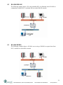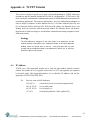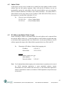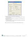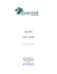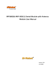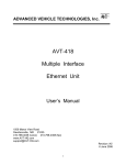
1
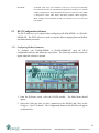
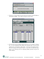
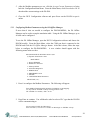
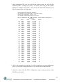
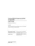
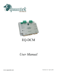
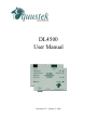
DL4500
User Manual
Revision 2.03 – January 3, 2008
Contents
1 General Operation and Applications ..................................................4
2 Hardware Specifications and Layout..................................................5
2.1 Operating Specifications..................................................................................5
2.2 Physical Specifications ....................................................................................6
2.3 Hardware Layout .............................................................................................6
3 Mode of Operation ................................................................................7
3.1 Online Mode of Operation ...............................................................................7
3.2 Offline Mode....................................................................................................7
3.2.1 BIOS Manager Options......................................................................7
4 Switch and LED Indicator Functions .................................................9
4.1 Switch Functions..............................................................................................9
4.2 Indicator Functions ..........................................................................................9
4.2.1 Power-Up and Reset Sequence ..........................................................9
4.2.2 Normal On-line Operation...............................................................10
4.2.3 On-Line, Power-Up and Reset Errors .............................................11
4.2.4 Off-Line Modes ................................................................................12
5 Configuration ......................................................................................13
5.1 Device Installer ..............................................................................................13
5.1.1 IP Address........................................................................................13
5.1.2 Telnet................................................................................................16
DF1 MultiMaster .............................................................................18
Standard Tunnel...............................................................................19
Modbus TCP ....................................................................................20
5.2 ComPort Redirector .......................................................................................21
5.2.1 Configuration...................................................................................21
5.2.2 Port Settings.....................................................................................23
5.3 DL32 Configuration Software .......................................................................24
5.3.1 Configuring Modbus Parameters ....................................................24
5.3.1 Configuring Modbus Parameters using the DL Offline Manager ...26
2
#815-1200 W73rd Ave, Vancouver, BC, V6P6G5, Canada
Phone: 888-387-3787 or 604-266-8547
www.equustek.com
5.4 Allan-Bradley Network Configuration ..........................................................28
5.4.1 DH+ Node Address..........................................................................28
5.4.2 DH+ Baud Rate ...............................................................................28
5.4.3 DH-485 Node Address .....................................................................29
5.4.4 DH-485 Baud Rate...........................................................................29
6 Firmware Upgrade..............................................................................30
6.1 Device Installer ..............................................................................................30
6.2 DL32 Configuration Software .......................................................................33
7 Wiring Diagrams.................................................................................35
7.1
7.2
7.3
7.4
DL4500 Pinout Diagram................................................................................35
RS-232 Null Modem Cable ...........................................................................35
DH+ Cable .....................................................................................................36
DH-485 Cable ................................................................................................36
8 DL4500 Typical Applications.............................................................37
8.1 DL4500-EDH+ ..............................................................................................37
8.2 DL4500-EDH-485 .........................................................................................38
8.3 DL4500-MEDH+...........................................................................................38
9 Frequently Encountered Problems ...................................................39
9.1 Device Installer cannot find the DL4500.......................................................39
9.2 Cannot communicate to DH+ node 0 using the DL4500-MEDH+ ...............40
Appendix A: TCP/IP Tutorial..............................................................41
A.1
A.2
A.3
A.4
IP Address......................................................................................................41
Subnet Mask...................................................................................................42
IP Address and Subnet Mask Couple.............................................................42
Valid IP Addresses.........................................................................................43
Appendix B:
RSLinx Setup ..................................................................45
3
#815-1200 W73rd Ave, Vancouver, BC, V6P6G5, Canada
Phone: 888-387-3787 or 604-266-8547
www.equustek.com
1
General Operation and Applications
The DL4500 hardware platform was designed to be a gateway which interfaces your
Ethernet TCP/IP or Modbus TCP Networks to AB’s Data Highway Plus (DH+), Remote
I/O, or DH-485 networks. Thus extending the life of existing Allen-Bradley PLC’s and
SLC’s without Ethernet Interfaces. It comes in a DC powered Din-Rail Mountable
compact cabinet for ease of portability and installation. The DL4500 combines the
Lantronix Ethernet Microprocessor with our proven A-B interface.
The DL4500 comes with a RJ-45 Connector for the 10 Base-T Ethernet link, and a 3 pin
Phoenix plug for connection to A-B networks. Power is supplied via a 2 pin Phoenix
type plug which allows for 9-27 Volts DC to be connected. Included is a RS232 DB9
Configuration Port for access to the BIOS and Flash Burn Utilities.
Configuration of the operating parameters is done quickly and easily via the Ethernet
Link by Telnet or the supplied Lantronix Device Installer software. Serial port
encapsulation of the DF1 protocol over TCP/IP is handled by the supplied COM Port
Redirector software also supplied by Lantronix. Current releases of the software can be
obtained from Lantronix’s Website.
Modbus TCP communication is handled by any generic Modbus TCP driver, tested ones
include Citect, Parijat, and Kepware. There is also the option of RAW tunneling of DF1
using other Ethernet TCP/IP drivers such as Kepware.
4
#815-1200 W73rd Ave, Vancouver, BC, V6P6G5, Canada
Phone: 888-387-3787 or 604-266-8547
www.equustek.com
2
Hardware Specifications and Layout
The DL4500 Hardware Platform has the following specifications.
2.1
Operating Specifications
Our DH+/RIO versions A-B Channel allows Synchronous Transformer Coupled SDLC
connection to Allen Bradley DH+ or RI/O. Speeds of 57.6K, 115.2K and 230.4K Baud
are available in both networks.
Our DH-485 versions A-B Channel allows for Isolated DH-485 (RS485) connection to
Allen Bradley DH-485 network. Speeds of 4800, 9600 and 19.2K (default) Baud are
available.
Ethernet Channel allows 10 Base-T connections to TCP/IP and other Ethernet networks.
Currently Full and Half Duplex DF1 protocol with BCC error checking is tunneled over
the Ethernet TCP/IP link. Modbus TCP makes use of our proven Modbus to AB network
interoperability.
Simple Parameter Configuration using menu driven Windows based Programs via
Ethernet 10 Base-T.
Configuration and Reset Pushbuttons go into BIOS features and Flash Setup and do a full
Hardware Reset.
Operating Parameters are stored in Non-Volatile Serial EEPROM.
The DL4500 uses FLASH upgradeable firmware from either the supplied DL32
configuration program or once can use a HyperTerminal type program set to 9600,N,8,1
and XON/XOFF flow control.
Bi-Color (Green/Red) LED’s for Ethernet and A-B Channels indicates activity and status.
Green POWER LED indicates power on.
Green LED’s for Ethernet Link and Tunneling Status.
Red LED for Ethernet Diagnostic Status.
5
#815-1200 W73rd Ave, Vancouver, BC, V6P6G5, Canada
Phone: 888-387-3787 or 604-266-8547
www.equustek.com
2.2
Physical Specifications
Dimensions: 1.2" H x 4.75" D x 3.2" W (30.4 x 120.7 x 81.3 mm) - Weight 0.56 Lbs (0.2 Kg)
Installation: Metal Enclosure; Desktop, # 8 Bolts, or Din Rail Mounting
Operating Environment: 32 to 122 °F (0 to 50 °C)
Storage: -40 to 185°F (-40 to 85°C)
Humidity: 5% to 95% non-condensing
Power: 9-27V DC - 1.8 Watts
2.3
Hardware Layout
This Section contains information of the physical position and purpose of the components of the
DL4500.
The top row contains the following connectors. Going left to right.
• 2 pin Power Connector
• A-B Network 3 pin Screw terminal (Phoenix Type)
The LED’s on the left side going from top to bottom.
• Ethernet Activity (TX/RX)
• A-B Network Status
• DL4500 Operating Mode and Status.
The LED’s on the right side going from top to bottom.
• Ethernet Activity (Port TX/RX)
• Lantronix COBOX Diagnostic LED.
• 10 Base-T Ethernet Link Status
The RESET pushbutton is on the left side, the Configure pushbutton is on the right side.
The bottom side of the DL4500 has the following connectors: Going Left to Right.
• 9 Pin DM9M connector for Configuring the BIOS and Firmware
• RJ-45 connector for 10 Base-T Ethernet communications
6
#815-1200 W73rd Ave, Vancouver, BC, V6P6G5, Canada
Phone: 888-387-3787 or 604-266-8547
www.equustek.com
3
Mode of Operation
3.1
Online Mode of Operation
Online Mode is the normal operating Mode of the DL4500. In this mode the Channels
are now configured as they are defined by the A-B Network and Configuration. The
DL4500 is ready to interface your equipment.
The Reset pushbutton automatically puts the DL4500 into Online mode.
3.2
Offline Mode
Once the Configure Pushbutton is Pressed the Offline BIOS Manager is started. Using
either the DL32 configuration software and the “DL Offline Manager” option or a
Windows Hyper Terminal type program with com port settings of 9600 Baud, 8,N,1 and
Xon/Xoff flow control.
BIOS MANAGER for DL4500-ENET- Revision 1.01 Oct 15,03
(c) Equus Technologies. 2003
MAIN MENU
1 - Restore EEPROM to Factory settings
2 - WRITE new Firmware
3 - Memory DUMP
4 - OFF-LINE Diagnostics
5 - DEBUG Mode
6 - FIRMWARE Version
7 - ONLINE
MAKE SELECTION (1-7) -
3.2.1
BIOS Manager Options
Restore EEPROM to factory settings
Once pressed you will be asked “Restore EEPROM to defaults (Y/N)?” If the answer
is “Y”es then the Online parameters will be reset to defaults of Address 1, and
settings of 9600,N,8,1 on the communication Channel to the COBOX.
Write New Firmware
Once pressed the message “This *WILL* overwrite DATALINK system code enter
(Y/N) to proceed” will be displayed. Hit “Y” and the next message will appear
telling you that it is alright to send the new firmware to the Flash;
ERASING FLASH, PLEASE WAIT...
SEND FIRMWARE TEXT FILE NOW...
7
#815-1200 W73rd Ave, Vancouver, BC, V6P6G5, Canada
Phone: 888-387-3787 or 604-266-8547
www.equustek.com
Once the message to send the firmware appears then either click on the “Burn Flash
System File” button to select the .txt file to send, or send the Text File under
HyperTerminal.
Wait for an “*A-OK* BURN COMPLETE!” message to appear.
Memory Dump
This is used to display the RAM memory of the DL4500. This should only be done
after contacting Equustek Solutions to debug problems.
Off-Line Diagnostics
Starts a series of tests to test the DL4500’s hardware and should only be done if
instructed so by a trained person.
Debug Mode
Starts up a DL4500 internal Debug mode that can be used by trained personnel to
debug problems and check hardware configuration and operation.
Firmware Version
Once selected the current DL4500 model and version numbers will be displayed. Can
be used to check the correct firmware was burnt into the Flash or if the DL4500 has
the most up to date firmware in the Flash.
Online
Does a soft “software” reset of the unit to put it online. This will NOT reset the
COBOX (Ethernet) hardware.
8
#815-1200 W73rd Ave, Vancouver, BC, V6P6G5, Canada
Phone: 888-387-3787 or 604-266-8547
www.equustek.com
4
Switch and LED Indicator Functions
4.1
Switch Functions
Reset Pushbutton
The Reset pushbutton will perform a complete hardware reset of the DL4500. It is
identical to a complete power cycle and will cause the DL4500 to go through its LED
start-up sequence as defined in Section 5.2.1. A complete hardware reset is needed on
changing any online operating parameters.
Configure Pushbutton
The Configure pushbutton takes the DL4500 out of On-Line operation mode and puts it
in the BIOS Manager mode. When this mode has been entered the Ethernet and Status
will be RED and A-B Network will be out. To put the unit back On-line it is necessary to
either press the Reset or cycle the DC power supplied to the DL4500.
4.2
Indicator Functions
4.2.1
Power-Up and Reset Sequence
On Power-up or after the Reset button has been pressed the DL4500 executes a self
diagnostic check-up or the ram and flash firmware. The correct LED indicator sequence
to show the DL4500 is functioning properly is as follows: After all LEDS go out.
LED
Power
Status
A-B Network
Ethernet
Status
Green Continuously
Green for 0.5 seconds
Green for 0.5 seconds
Green for 3 seconds
After this sequence the DL4500 goes into the On-line mode of Operation. The LED
indicators will behave in the certain way defined by the DL4500 model used. Most likely
the A-B Network will be solid or flashing depending on the A-B Network used.
9
#815-1200 W73rd Ave, Vancouver, BC, V6P6G5, Canada
Phone: 888-387-3787 or 604-266-8547
www.equustek.com
4.2.2
Normal On-line Operation
The following is a description of the normal operation of the LED’s on the DL4500.
LEFT LED’s
Power
Description of Operation
Green Indicates Power is being supplied to the DL4500.
Ethernet
Flashes GREEN for 0.5 seconds when a character is Received or
Transmitted. If Characters are being received of transmitted faster
than this then it might appear the LED is on SOLID. Flashes RED
for 0.5 seconds if a NAK is received or transmitted. Will also
flash if all serial communication buffers are full.
A-B Network
(DH+ )
On Hardware Reset will flash GREEN and RED until a valid DH+
network is detected. This is the AUTO BAUD Rate detection
mode, the DL4500 will automatically connect at the DH+ speeds
of 57.6K, 115.2K and 230.4K Baud. LED will switch to on solid
once the DL4500 is on the DH+ network as a valid node address.
LED will flash GREEN when the DH+ is set to a certain Baud rate
but is not on network.
(DH-485)
On Hardware reset the A-B Network will flash GREEN at a 1
second rate when the DH-485 is not on network. Once a valid
network is running the LED will flash GREEN much more rapidly
(approx. every 0.1 seconds), the rate depends on how busy the
network is.
Status
Used for Determining Operating Mode and DL4500 Status
RIGHT LED’s
Description of Operation
TX/RX
Lights Solid green to indicate an Ethernet socket is idle. Blinks
green to indicate an Ethernet socket has been established and
active.
Diagnostic
Blinks or lights solid red in combination with TX/RX led to
indicate diagnostics and error detection.
Link
Lights Solid Green to indicate Ethernet Port is connected to the
10Base-T network.
10
#815-1200 W73rd Ave, Vancouver, BC, V6P6G5, Canada
Phone: 888-387-3787 or 604-266-8547
www.equustek.com
4.2.3 On-Line, Power-Up and Reset Errors
The following table describes the meaning of LED patterns if the internal diagnostic tests
detect an error on Reset/Power-Up.
LED Pattern
Description of Problem
Ethernet, A-B Network,
and Status Flashing
RED
The flash has not be burnt properly and the A-OK was
not transmitted. Please reburn the flash with the correct
text file. Contact Customer Support for help.
Ethernet, A-B Network,
and Status Solid RED
The BIOS has been corrupted. A new Flash Chip has to
be supplied by the factory. Please contact Customer
support.
Start-up Sequence keeps
repeating
The DL4500 EEPROM is corrupt.. Please Restore to
Factory Settings (See Section 4.3) and then reconfigure
the unit.
A-B Network
Flashing RED
There is a duplicate node on the A-B network. The
DL4500 has been assigned a node address that is already
in use.
Right TX/RX and
Diagnostic
Red solid, green (TX/RX) blinking:
1x:EEPROM checksum error
2x:RAM error
3x:Network controller error
4x:EEPROM checksum error
5x:Duplicate IP address on the Ethernet Network
6x:Software does not match hardware
Red blinking. Green (TX/RX) blinking:
4x: Faulty Ethernet connection
5x:No DHCP response received
11
#815-1200 W73rd Ave, Vancouver, BC, V6P6G5, Canada
Phone: 888-387-3787 or 604-266-8547
www.equustek.com
4.2.4
Off-Line Modes
The following table describes the meaning of LED patterns in the different Off-Line
modes of operation.
LED Pattern
Description of Operation
Ethernet & Status Solid
RED
BIOS Manager
Ethernet & Status Solid
Green A-B Network
Solid Red
Offline Hardware Diagnostics Testing Mode
Ethernet Solid Red A-B
Network & Status Solid
Green
Offline Debug Mode
12
#815-1200 W73rd Ave, Vancouver, BC, V6P6G5, Canada
Phone: 888-387-3787 or 604-266-8547
www.equustek.com
5
Configuration
The following sections describe how to setup and configure your DL4500 for the desired
online operating parameters. To configure your DL4500, the following software will be
needed.
Configuration Software
• Device Installer
-
•
ComPort Redirector
-
•
DL32 Configuration
-
Used to assign IP address and update Lantronix
daughter board firmware.
Creates a virtual COM port and redirects it to the PC’s
Ethernet port.
Used to map Modicon registers/coils to Allan-Bradley
data files with the DL4500-MEDH+ or MEDH-485.
After the IP address of the DL4500 is assigned, you must then telnet to the DL4500 to
setup the internal communications between the Lantronix daughter board and the
DL4500 motherboard. These settings are reset every time an IP address is assigned.
5.1
Device Installer
The Device Installer is used to configure the IP address of the DL4500 as well as
configure the internal communication settings between the Lantronix daughter board and
the DL4500 mother board. The most recent version of Device Installer is Device
Installer 3.6.
5.1.1
IP Address
To assign an IP address to the DL4500, open the Device Installer Software. You will
then see a screen as shown below.
13
#815-1200 W73rd Ave, Vancouver, BC, V6P6G5, Canada
Phone: 888-387-3787 or 604-266-8547
www.equustek.com
The following steps are used to assign an IP address to the DL4500.
1. Click on the Search button to have the Device Installer find the DL4500. If the
Device Installer finds the DL4500, the device should appear. If the device cannot be
found then follow the instructions at the end of the IP Address section.
2. Highlight the device and click on the Assign IP button. Choose the “Assign a specific
IP address” option and click Next. The following window will appear.
3. Enter the desired IP address, subnet mask, and default gateway (if required) and click
Next.
14
#815-1200 W73rd Ave, Vancouver, BC, V6P6G5, Canada
Phone: 888-387-3787 or 604-266-8547
www.equustek.com
4. To assign the chosen IP address to the DL4500, click the Assign button. When the IP
address is assigned, a message stating that the IP address was successfully assigned
should appear. Click the Finish button to close the screen and go back to the main
menu.
15
#815-1200 W73rd Ave, Vancouver, BC, V6P6G5, Canada
Phone: 888-387-3787 or 604-266-8547
www.equustek.com
Device Not Found
If for some reason the Device Installer cannot find the DL4500 on the Ethernet network,
follow the steps below.
1. Click the Assign IP button and the following screen will appear.
2. Enter MAC address of the DL4500 and click Next. This can be found on the bottom
of the DL4500. The Device Installer should now find the device. Now follow the
steps at the beginning of the IP Address section to assign an IP address. If for some
reason the device still cannot be found, see section 9.1 Device Installer Cannot Find
the DL4500.
5.1.2
Telnet
After the IP address of the DL4500 is assigned, the internal communication parameters
that the Lantronix daughter board uses to communicate with the DL4500 motherboard
must be configured. Depending on the model of DL4500 that is being used, there are
different Telnet settings that must be set. The Telnet settings for each model of DL4500
are shown below in the following order: DF1 MultiMaster, Standard Tunnel, and Modbus
TCP.
To start a telnet session, there are two ways that can be used. The first method uses the
Device Installer while the second uses a DOS command prompt.
16
#815-1200 W73rd Ave, Vancouver, BC, V6P6G5, Canada
Phone: 888-387-3787 or 604-266-8547
www.equustek.com
Telnet using Device Installer
Open Device Installer and click search to find the DL4500. Once the device is found,
double click on the device and three tabs will appear on the right window frame. Select
the Telnet Configuration tab and the following should appear.
Make sure port 9999 is entered and click Connect to begin the Telnet session.
Telnet using the DOS Command Prompt
Open a DOS command prompt window to begin. At the prompt, type telnet then a space,
the IP address of the unit then a space, and then the port 9999. After this is entered, press
Enter to begin a telnet session. The following is an example of how to begin a telnet
session from the command prompt.
C:\>telnet 192.168.2.2 9999
On the following pages are the Telnet settings for the different DL4500 models. After
starting a telnet session, you must press the Enter key to bring up the main menu.
17
#815-1200 W73rd Ave, Vancouver, BC, V6P6G5, Canada
Phone: 888-387-3787 or 604-266-8547
www.equustek.com
DF1 MultiMaster
The following menu will appear after starting a telnet session.
Multi-Master DF1
1) TCP/IP Network Settings:
Ethernet Autodetect
IP addr 192.168.2.2, no gateway set, netmask 255.255.255.000
2) DF1 Settings:
Protocol ................. DF1 Full-Duplex
Serial Interface ......... RS232 19200,8,N,1
Check Sum ................ CRC (16-bit)
Redirector Sockets ....... 2 (port:03001)
Raw Tunneled Sockets ..... 2 (port:10001)
3) MSG Block Remote IP Routing Table:
(* None Defined *)
R)eset all to factory Defaults
S)ave all to EEPROM and Quit
Q)uit without saving
Select Command or parameter set (1,2,R,S,Q) to change:
To set the proper Telnet settings, follow the steps below:
1. Press R to restore Factory Defaults.
2. Press 2 to configure the DF1 Settings. Input the values so that they match what is
shown below. The values shown in the parentheses are the current settings. To keep
the current settings, press Enter.
Interface Type (1=RS232 2=RS422/RS485+4-wire 3=RS485+2-wire) (00001) ?
Enter serial parameters (19200,8,N,1) 115200,8,n,1
Use DF1 16-bit CRC CheckSum? (Y) N
You have 4 total incoming sockets:
Number to use for Lantronix Redirector (00002) ? 0
Number to use for Raw DF1 in TCP 4
TCP port to use for Raw DF1 (10001) ?
When asked about the incoming sockets, enter 0 for Number to use for Lantronix
Redirector. This will allow up to 4 connections to be used on port 10001. The
default for this setting is 2.
Note that the DL4500 only supports BCC error checking at this time.
3. Press S to save the new settings and end the telnet session.
4. Press the reset button on the DL4500 to put it online.
18
#815-1200 W73rd Ave, Vancouver, BC, V6P6G5, Canada
Phone: 888-387-3787 or 604-266-8547
www.equustek.com
Standard Tunnel
The following menu will appear after starting a telnet session.
Change Setup:
0 Server configuration
1 Channel 1 configuration
2 Channel 2 configuration
5 Expert settings
6 Security
7 Factory defaults
8 Exit without save
9 Save and exit
Your choice ?
To set the proper Telnet settings, follow the steps below:
1. Press 7 and then Enter to restore Factory Defaults.
2. Press 1 and then Enter to configure the Channel 1 configuration. Input the values so
that they match what is shown below. The values shown in the parentheses are the
current settings. To keep the current settings, press Enter. The only value that needs
to be changed is the baud rate.
Baudrate (9600) ? 115200
I/F Mode (4C) ?
Flow (00) ?
Port No (10001) ?
ConnectMode (C0) ?
Remote IP Address : (000) .(000) .(000) .(000)
Remote Port (0) ?
DisConnMode (00) ?
FlushMode
(00) ?
DisConnTime (00:00) ?:
SendChar 1 (00) ?
SendChar 2 (00) ?
3. Press 9 and then Enter save the new settings and end the telnet session.
4. Press the reset button on the DL4500 to put it online.
19
#815-1200 W73rd Ave, Vancouver, BC, V6P6G5, Canada
Phone: 888-387-3787 or 604-266-8547
www.equustek.com
Modbus TCP
The following menu will appear after starting a telnet session.
Modbus/TCP to RTU Bridge Setup
1) Network/IP Settings:
IP Address ................. 192.168.2.2
Default Gateway ............ --- not set --Netmask .................... 255.255.255.000
2) Serial & Mode Settings:
Protocol ................... Modbus/RTU,Slave(s) attached
Serial Interface ........... 9600,8,N,1,RS232,DB25
3) Modem Control Settings:
DCD Output ................. Fixed High/Active
CTS Output ................. Fixed High/Active
4) Advanced Modbus Protocol settings:
Slave Addr/Unit Id Source .. Modbus/TCP header
Modbus Serial Broadcasts ... Disabled (Id=0 auto-mapped to 1)
MB/TCP Exception Codes ..... Yes (return 00AH and 00BH)
Char, Message Timeout ...... 00050msec, 05000msec
D)efault settings, S)ave, Q)uit without save
Select Command or parameter set (1..4) to change:
To set the proper Telnet settings, follow the steps below:
1. Press D to restore Factory Defaults.
2. Press 2 to configure the Serial and Mode Settings. Input the values so that they match
what is shown below. The values shown in the parentheses are the current settings.
To keep the current settings, press Enter. The only value that needs to be changed is
the baud rate.
Attached Device (1=Slave 2=Master) (1)
Serial Protocol (1=Modbus/RTU 2=Modbus/ASCII) (1)
Use serial connector (1=CH1 2=CH2) (1)
Interface Type (1=RS232 2=RS422/RS485+4-wire 3=RS485+2-wire) (1)
Enter serial parameters (9600,8,N,1) 115200,8,n,1
The main menu should now show 115200, 8, N, 1, RS232, DB25 for the Serial
Interface under Serial and Mode Settings.
3. Press S to save the new settings and end the telnet session.
4. Press the reset button on the DL4500 to put it online.
20
#815-1200 W73rd Ave, Vancouver, BC, V6P6G5, Canada
Phone: 888-387-3787 or 604-266-8547
www.equustek.com
5.2
ComPort Redirector
The ComPort Redirector is used to redirect a virtual COM port to the Ethernet port. This
software is needed since RSLinx does not offer an Ethernet DF1 driver. Therefore an
RS-232 serial driver is used and the ComPort Redirector redirects the data to the Ethernet
port. The ComPort Redirector software is not needed if you have a Modbus TCP model.
The most recent version of the ComPort Redirector is ComPort Redirector 3.1.0.1.
5.2.1 Configuration
To begin configuring the ComPort Redirector, open the software and the following
screen will appear.
To configure the ComPort Redirector, use the following steps.
1. Click the Com Setup button to add a virtual COM port to be redirected.
following screen will appear.
The
2. Select the COM port that you want to use a virtual COM port and click OK. You will
then be returned to the first screen. Whenever a COM port is added or removed, you
will need to reboot your PC before the COM port can be used. The PC can be
rebooted after the ComPort Redirector has been configured.
21
#815-1200 W73rd Ave, Vancouver, BC, V6P6G5, Canada
Phone: 888-387-3787 or 604-266-8547
www.equustek.com
3. From the main screen, select the COM port that you want to configure from the drop
down menu.
4. Click the Add IP button to assign an IP address and TCP port to where that COM port
will be redirected to. The IP address will be the address assigned to the DL4500. A
window will appear as shown below. Depending on the model of DL4500 that you
have (DF1 MultiMaster or Standard Tunnel), follow the steps in the appropriate
section.
5. Enter the IP address of the DL4500 in the box labeled Host. Do not include leading
zeros when entering the IP address. This will cause the ComPort Redirector to be
unsuccessful in connecting to the DL4500.
6. Enter 10001 for the TCP port and click OK to close the window.
7. From the main window, click the Port Settings button. A new window will appear.
8. Put a checkmark beside Timeout Reconnect, Server Reconnect, and Raw Mode. For
more details about the Port settings, see section 5.2.2 Port Settings.
9. Click OK to close the window. From the main window, Save and then Close to
finalize the setup. You may be prompted to reboot your computer at this point.
22
#815-1200 W73rd Ave, Vancouver, BC, V6P6G5, Canada
Phone: 888-387-3787 or 604-266-8547
www.equustek.com
5.2.2 Port Settings
The follow section provides more details about the different port settings available with
the ComPort Redirector software. This information was obtained from the Lantronix
ComPort Redirector User Manual.
Timeout Reconnect:
If checked, Com Port Redirector re-establishes the connection if the connection
times out. When auto-reconnecting, Com Port Redirector tries to reconnect until
the connection succeeds or you click the Cancel button in the pop-up connection
dialog box. If the port was closed by the communications application or by
clicking Disconnect, Com Port Redirector does not try to auto-reconnect.
Server Reconnect:
If checked, Com Port Redirector re-establishes the connection if the server closes
it. When auto-reconnecting, Com Port Redirector tries to reconnect until the
connection succeeds or you click the Cancel button in the pop-up connection
dialog box. If the port was closed by the communications application or by
clicking Disconnect, Com Port Redirector does not try to auto-reconnect.
Inband Listen:
If checked, Com Port Redirector uses the inband redirector protocol on inbound
connections from a Lantronix server. This protocol allows settings like modem
signals, baud rate and parity to be exchanged between Com Port Redirector and
the server.
Connection Timeout:
Specifies the maximum number of seconds that the Com Port Redirector waits for
a connection to be made before giving up on this attempt. If Timeout Reconnect
is enabled, each connection attempt lasts this long. If Timeout Reconnect is
disabled, the connection attempt fails after this interval and no more attempts are
made.
Force v2 Protocol:
If checked, Com Port Redirector always uses the version 2 protocol. This protocol
has a quicker connect time than version 3, but lacks the version 3 feature set.
Version 3 lets the communication application set the Data Terminal Ready (DTR)
and Request To Send (RTS) states, byte size, stop bits, parity, and the read the
state of Clear To Send (CTS), Data Set Ready (DSR), and Carrier Detect (CD).
CoBox, UDS, XPort, and XPress products do not support version 2 or 3 Com Port
Redirector protocols. Therefore, use Raw Mode with CoBox, UDS, XPort, and
XPress products.
No Net Close:
If checked, prevents the network connection from being dropped when the
communications application is closed. To drop the connection, click the
Disconnect button in the Com Port Redirector Configuration window. This
allows applications to close and reopen ports, without waiting for the network
connection to be re-established and negotiated.
23
#815-1200 W73rd Ave, Vancouver, BC, V6P6G5, Canada
Phone: 888-387-3787 or 604-266-8547
www.equustek.com
Raw Mode:
If checked, forms a raw TCP connection to the server’s serial port, accelerating
the connection between the communications application and the server, without
sending configuration or status information from the PC to the server. Raw Mode
is designed for CoBox, UDS, XPort, and XPress products. When using Raw
Mode, configure Com Port Redirector and your Lantronix server to use the same
port number.
5.3
DL32 Configuration Software
The DL32 software is only required when configuring a DL4500-MEDH+ or a DL4500MEDH-485. The DL32 software is used to setup the address mapping between Modbus
and Allan-Bradley networks.
5.3.1
Configuring Modbus Parameters
To configure your DL4500-MEDH+ or DL4500-MEDH-485, open the DL32
configuration software and follow the steps below. The following welcome screen will
appear when the software is opened.
1. From the Welcome screen, select the DL4500 models. The Main Menu should
appear.
2. Select the COM port that you have connected to the DL4500 and Click on the
Configure / Open File button. The Configuration Menu for the DL4500 will appear
as shown below.
24
#815-1200 W73rd Ave, Vancouver, BC, V6P6G5, Canada
Phone: 888-387-3787 or 604-266-8547
www.equustek.com
3. Click the Set / Change Modbus Operating Parameters button to setup the Modbus to
Allan-Bradley mapping. A new window will appear as shown below.
4. Fill in the table with the Modbus registers/coils that are to be mapped to AB data
files. For more information about setting up the translation table, see the DL3500
application note “DL3500-DH+ Modbus Slave”. The setup of the translation table is
the same for both the DL3500 and the DL4500. If more slots are needed than what is
shown, see the following section on configuring Modbus parameters using the DL
Offline Manager.
25
#815-1200 W73rd Ave, Vancouver, BC, V6P6G5, Canada
Phone: 888-387-3787 or 604-266-8547
www.equustek.com
5. After the Modbus parameters are set, click the Accept Current Parameters to bring
back the Configuration Main Menu. From the Main Menu, click Download to DL to
download the current settings to the DL4500.
6. Close the DL32 Configuration software and press Reset on the DL4500 to put it
online.
5.3.1
Configuring Modbus Parameters using the DL Offline Manager
If more than 8 slots are needed to configure the DL4500-MEDH+, the DL Offline
Manager can be used to setup the translation table. Using the DL Offline Manager, up to
40 slots can be configured.
To use the DL Offline Manager, open the DL32 Configuration software and choose the
DL4500 models. From the Main Menu, select the COM port that is connected to the
DL4500 and Click the DL Offline Manager button. After this is done, follow the steps
below to configure the DL4500-MEDH+. A new window should appear with the
following menu in the text box.
BIOS MANAGER for DL4500-2.00-Dec.10,04
(c) Equustek Solutions Inc. 2004
MAIN MENU
1 - Restore EEPROM
2 - WRITE new Firmware
3 - Memory DUMP
4 - OFF-LINE Diagnostics
5 - DEBUG Mode
6 - FIRMWARE Version
7 - ONLINE
8 - CONFIGURE Model Parameters
SELECTION (1-8) -
1. Press 8 to configure the Modbus Parameters. The following will appear.
Enter Modbus Translation table parameters for Modicon to AB mapping.
AT Any time hit <ENTER> To Keep existing parameter value
Hit <ENTER> To continue, <ESC> to exit
2. Press Enter to continue. You will then be asked to select a PLC type that the DL4500
will be communicating to.
Select A-B PLC TYPE: SLC/Micrologix
Enter 0 for PLC5, 1 for PLC3 or 2 for SLC or Micrologix or <ENTER> to keep:
26
#815-1200 W73rd Ave, Vancouver, BC, V6P6G5, Canada
Phone: 888-387-3787 or 604-266-8547
www.equustek.com
3. After selecting the PLC type you will then be asked to enter the values for the
translation table. Leading zeros need to be entered when using the DL Offline
Manager to configure the DL4500. After entering the translation parameters, press
Enter to proceed to the end of the table.
Program Modbus/A-B Translation Parameters
Hit <ENTER> to keep exsiting value or Type in New Value
Need to enter Leading Zeros. IE. file 7 = 007
Hit <ENTER> to Proceed any other key to exit now.
REC No Modbus Start Add. Modbus End Add. A-B Start Address Floating Point
(File:Word)
xxxxx
xxxxx
xxx:xxx
Yes/No
00
01
02
03
04
05
06
07
08
09
10
11
12
13
14
15
16
17
18
19
20
21
22
23
24
25
26
27
28
29
30
31
32
33
34
35
36
37
38
39
40001
30001
00001
00000
00000
00000
00000
00000
00000
00000
00000
00000
00000
00000
00000
00000
00000
00000
00000
00000
00000
00000
00000
00000
00000
00000
00000
00000
00000
00000
00000
00000
00000
00000
00000
00000
00000
00000
00000
00000
40010
30010
00016
00000
00000
00000
00000
00000
00000
00000
00000
00000
00000
00000
00000
00000
00000
00000
00000
00000
00000
00000
00000
00000
00000
00000
00000
00000
00000
00000
00000
00000
00000
00000
00000
00000
00000
00000
00000
00000
007:000
008:000
003:000
000:000
000:000
000:000
000:000
000:000
000:000
000:000
000:000
000:000
000:000
000:000
000:000
000:000
000:000
000:000
000:000
000:000
000:000
000:000
000:000
000:000
000:000
000:000
000:000
000:000
000:000
000:000
000:000
000:000
000:000
000:000
000:000
000:000
000:000
000:000
000:000
000:000
N
N
N
N
N
N
N
N
N
N
N
N
N
N
N
N
N
N
N
N
N
N
N
N
N
N
N
N
N
N
N
N
N
N
N
N
N
N
N
N
4. After all the parameters are entered you will be prompted to save the configuration.
Press Y to accept the current parameters, or N to discard the current parameters.
5. After this is done, close the DL32 Configuration software and press Reset on the
DL4500 to put it online.
27
#815-1200 W73rd Ave, Vancouver, BC, V6P6G5, Canada
Phone: 888-387-3787 or 604-266-8547
www.equustek.com
5.4
Allan-Bradley Network Configuration
The DH+ or DH-485 requires that every station on the network has its own node address.
This section describes the configuration of the DL4500 for the desired A-B network.
5.4.1
DH+ Node Address
The DH+ network allows up to 64 nodes on a network with addresses ranging from 0 to
63 decimal. The DL4500 DH+ node address is determined from the last octet of the IP
address assigned to the unit. The following table shows how the DH+ node address is
determined from the last octet of the IP address.
Node Address
0-63
0-63
0-63
0-63
Last Octet of IP address
0-63
64-127
128-191
192-255
If the last octet of the IP address is larger than 63, subtract 64 from the value until it falls
within the range of 0 to 63. This will be the DH+ node address in decimal. Since DH+
uses octal notation, a conversion decimal to octal will be needed.
Ex.
DL4500 with IP Address 192.168.2.170
Solution
Take the last octet and subtract and keep subtracting 64
until the value falls within the range of 0 to 63.
170 − 64 − 64 = 42
The DH+ node address is 42 decimal or 52 octal.
5.4.2
DH+ Baud Rate
The DH+ Baud rate on the DL4500 is auto detecting; whatever the existing network is set
to the DL4500 will use that baud rate. Valid rates of 57.6K, 115.2K and 230.4K Baud
are supported.
On Hardware Reset the A-B Network LED will flash GREEN and RED until a valid
DH+ network is detected. This is the AUTO BAUD Rate detection Mode and the
DL4500 will stay in this mode until a valid network is connected to the A-B Network
Connector. The A-B Network LED will then switch to on solid once the DL4500 is on
the DH+ network as a valid node address.
28
#815-1200 W73rd Ave, Vancouver, BC, V6P6G5, Canada
Phone: 888-387-3787 or 604-266-8547
www.equustek.com
5.4.3
DH-485 Node Address
The DH-485 network allows up to 32 nodes on a network with addresses ranging from 0
to 31 decimal. The DL4500 DH-485 node address is determined from the last octet of
the IP address assigned to the unit. The following table shows how the DH-485 node
address is determined from the last octet of the IP address.
Node Address
0-31
0-31
0-31
0-31
0-31
0-31
0-31
0-31
Last Octet of IP address
0-31
32-63
64-95
96-127
128-159
160-191
192-223
224-255
If the last octet of the IP address is larger than 31, subtract 32 from the value until it falls
within the range of 0 to 31. This will be the DH-485 node address in decimal.
Ex.
DL4500 with IP Address 192.168.2.170
Solution
Take the last octet and subtract and keep subtracting 32
until the value falls within the range of 0 to31.
170 − 32 − 32 − 32 − 32 − 32 = 10
The DH-485 node address is 10 decimal.
5.4.4
DH-485 Baud Rate
The DH-485 Baud rate will set itself to 19.2K if the Serial Interface was set to 19200 or
Higher. Otherwise it will use 9600 for a 9600 baud and 4800 for 4800 baud.
Serial Interface Speed
19200-115200 Baud
9600 Baud
4800 Baud
DH-485 Speed
19.2K Baud
9600 Buad
4800 Buad
29
#815-1200 W73rd Ave, Vancouver, BC, V6P6G5, Canada
Phone: 888-387-3787 or 604-266-8547
www.equustek.com
6
Firmware Upgrade
There may be times when the firmware in the DL4500 needs to be upgraded. Some of
theses times include installing newer firmware or switching from DF1 MultiMaster to
Standard Tunnel or vice versa.
The DL4500 has two different types of firmware that need to be upgraded. Depending on
what needs to be upgraded, one or both firmware may need to be upgraded. If switching
the firmware in the DL4500 from one model to another, then both of the firmwares will
need to be upgraded (ie. changing from DF1 MultiMaster to Standard Tunnel).
To upgrade the firmware in the DL4500, follow the procedure outlined below.
6.1
Device Installer
The Device Installer is used to upgrade the Ethernet firmware. To upgrade the Ethernet
firmware open the Device Installer and follow the procedures outlined below. You will
see the following window when the Device Installer is opened.
1. After opening the Device Installer, click the Search button. The Device Installer
should find the DL4500. If successful, the device should show up on the screen.
30
#815-1200 W73rd Ave, Vancouver, BC, V6P6G5, Canada
Phone: 888-387-3787 or 604-266-8547
www.equustek.com
2. Highlight the device by clicking on it and press the Upgrade button to install new
firmware. The following window will appear after pressing the Upgrade button.
3. Select the option Create a custom installation by specifying individual files as shown
above and click Next.
4. Select the firmware to be installed by clicking the browse button and choosing the
appropriate firmware file. After this is done, click Next.
31
#815-1200 W73rd Ave, Vancouver, BC, V6P6G5, Canada
Phone: 888-387-3787 or 604-266-8547
www.equustek.com
5. Select the No other files to install option and click Next to proceed.
6. To begin the firmware upgrade click Next.
7. If the firmware has been successfully installed, you will see the following screen.
The Device Installer can now be closed.
32
#815-1200 W73rd Ave, Vancouver, BC, V6P6G5, Canada
Phone: 888-387-3787 or 604-266-8547
www.equustek.com
6.2
DL32 Configuration Software
The DL32 Configuration Software is used to upgrade the firmware on the DL4500
motherboard. This firmware is responsible for the DH+ and DH-485 networks.
In order to upgrade the DL4500 firmware, follow the procedure below.
1. Open the DL32 Configuration and select DL4500 Models. You will see the following
screen.
2. Select the COM port attached to the DL4500 and click the DL Offline Manager
button. You will be prompted to press the configure button on the DL4500. The
following Menu will be shown in a new window.
BIOS MANAGER for DL4500-ENET- Revision 1.01 Oct.15,03
(c) Equus Technologies. 2003
MAIN MENU
1 - Restore EEPROM to Factory settings
2 - WRITE new Firmware
3 - Memory DUMP
4 - OFF-LINE Diagnostics
5 - DEBUG Mode
6 - FIRMWARE Version
7 - ONLINE
MAKE SELECTION (1-7) –
3. Press 2 to upgrade the firmware. A message will appear notifying that this will
overwrite the existing system code. Press Y to continue.
This *WILL* overwrite DATALINK system code enter (Y/N) to proceed Y
ERASING FLASH, PLEASE WAIT...
SEND FIRMWARE TEXT FILE NOW...
33
#815-1200 W73rd Ave, Vancouver, BC, V6P6G5, Canada
Phone: 888-387-3787 or 604-266-8547
www.equustek.com
4. After the message Send firmware text file now appears, press the button Select Flash
System File located in the top left corner of the window.
5. When the Send Flash System File button is pressed, a message box will appear asking
if the WRITE new Firmware option was selected. Click Yes to continue.
6. Select the desired firmware file and the DL4500 will begin upgrading the firmware.
Upon a successful install, the following text will appear.
*A-OK* BURN COMPLETE!
7. The DL32 Configuration Software can now be closed. Press the Reset button on the
DL4500 to put it online.
34
#815-1200 W73rd Ave, Vancouver, BC, V6P6G5, Canada
Phone: 888-387-3787 or 604-266-8547
www.equustek.com
7
Wiring Diagrams
This section contains the information required for connecting your DL4500 to Allan
Bradley’s DH+ and DH-485 networks. It also contains wiring diagrams for building an
RS-232 null modem cable which is used to connect serially to the DL4500.
7.1
DL4500 Pinout Diagram
Below is an image of the DL4500 that shows the numbering of the DH+/DH-485
connector. Pin 1 is located closest to the power connector.
7.2
RS-232 Null Modem Cable
The RS-232 null modem cable is used to serially connect to the DL4500 in order to use
the DL Offline Manager or configure the device using the DL32 Configuration Software.
35
#815-1200 W73rd Ave, Vancouver, BC, V6P6G5, Canada
Phone: 888-387-3787 or 604-266-8547
www.equustek.com
7.3
DH+ Cable
Below is a diagram of the DL4500 DH+ connector. Pin 1 is the pin closest to the power
connector.
7.4
DH-485 Cable
Below is a diagram of the DL4500 DH-485 connector. Pin 1 is the pin closest to the
power connector. Note that Shield cannot be replaced by Common.
36
#815-1200 W73rd Ave, Vancouver, BC, V6P6G5, Canada
Phone: 888-387-3787 or 604-266-8547
www.equustek.com
8
DL4500 Typical Applications
The DL4500 is designed to be used in applications using Ethernet to communicate with
devices on a DH+ or DH-485 network. Some of the typical applications that use the
DL4500 are shown in this section.
8.1
DL4500-EDH+
The following example shows a PC using tunneled DF1 over Ethernet with a DL4500 to
communicate with the PLC’s and other devices on the DH+ network.
37
#815-1200 W73rd Ave, Vancouver, BC, V6P6G5, Canada
Phone: 888-387-3787 or 604-266-8547
www.equustek.com
8.2
DL4500-EDH-485
The following example shows a PC using tunneled DF1 over Ethernet with a DL4500 to
communicate with the PLC’s and other devices on the DH-485 network.
8.3
DL4500-MEDH+
The following example shows a SCADA server using a DL4500 to acquire data from
PLC’s and devices on the DH+ network.
38
#815-1200 W73rd Ave, Vancouver, BC, V6P6G5, Canada
Phone: 888-387-3787 or 604-266-8547
www.equustek.com
9
Frequently Encountered Problems
This section outlines some of the most frequently encountered problems when trying to
configure the DL4500. If the problem you are having is not located in this section, please
contact technical support.
9.1
Device Installer cannot find the DL4500
If for some reason the Device Installer software cannot find the DL4500 on the Ethernet
network, it can possibly be because one of the following problems:
1. Another device on the Ethernet network has the same IP address that is
currently assigned to the DL4500.
2. The DL4500 may have an IP address in which the network ID portion
of the address does not match the network ID that is being used by the
Ethernet network.
In order to assign an IP address to the DL4500, the address resolution protocol (ARP)
will be used. Using the ARP command will only temporarily change the IP address in
the device. To configure the unit so that it keeps the IP address, you must telnet to the
unit and change its IP address from the configuration menu. In order for the ARP
command to work in Windows 95, the ARP table on the PC must have at least one IP
address defined other than its own. To use the ARP command to assign a temporary IP
address, follow the steps below.
1. Open an MS DOS command prompt window.
2. At the command prompt, type the following to view the ARP table.
arp –a
To add another value to the ARP table, ping another device on the current network.
3. Use the following ARP command to add the DL4500 to the ARP table.
arp –s xxx.xxx.xxx.xxx aa-bb-cc-dd-ee-ff
The first entry after the arp –s is the IP address that you wish to temporarily assign to
the DL4500 (denoted by xxx.xxx.xxx.xxx). The next entry is the MAC address of the
DL4500 which can be located on the bottom of the unit (denoted by aa-bb-cc-dd-eeff).
4. Open a telnet session to the DL4500 using port 1. This is done by typing the
following at the command prompt.
telnet xxx.xxx.xxx.xxx 1
39
#815-1200 W73rd Ave, Vancouver, BC, V6P6G5, Canada
Phone: 888-387-3787 or 604-266-8547
www.equustek.com
The connection will fail when this is done, but will temporarily change the IP address
of the DL4500 to xxx.xxx.xxx.xxx.
5. Finally open another telnet session but this time to port 9999 as follows.
telnet xxx.xxx.xxx.xxx 9999
6. Set the IP address of the DL4500 by changing the Network or Server settings from the
main menu of the telnet session. The IP address assigned here will become the
permanent IP address of the DL4500.
9.2
Cannot communicate to DH+ node 0 using the DL4500-MEDH+
Any Modbus client that is trying to read or write data to a PLC or device on the DH+ or
DH-485 at node 0 will not work. The reason for this is because the Modbus protocol uses
slave ID 0 as the broadcast address. All Modbus slaves recognize the broadcast address
but do not send a response when a broadcast message has been received.
40
#815-1200 W73rd Ave, Vancouver, BC, V6P6G5, Canada
Phone: 888-387-3787 or 604-266-8547
www.equustek.com
Appendix A: TCP/IP Tutorial
This section is design to guide you to gain a brief understanding to TCP/IP addressing
mechanism and the meaning behind the DL4500 IP configurations. TCP/IP suite is the
most commonly used Ethernet communication protocol in both industrial and commercial
networking applications. The protocol implements a two-level addressing mechanism in
order to assign a computer or other Ethernet device (1) its Node Address (Host ID), and
(2) its Network Address (Network ID). With the node address, the Ethernet device can
identify itself on a network; with the network address, the Ethernet device can identify
the network in which it belongs to, and facilitate communication among computers across
different networks.
Analogy
The node address is analogous to the suite number in an apartment, and the
network address is equivalent to the residential number of the entire apartment
building. When my friends want to visit me, I must give them both my suite
number and the residential number of the apartment in which I live in, else they
wouldn’t be able to find my place.
A.1
IP Address
TCP/IP uses a four-segmented number set to store the node address and the network
address; the number in every segment varies from 0 to 255, and segments are separated
by decimal points. This segmented number set is called the IP Address, and has the
appearance of XXX.XXX.XXX.XXX.
Ex.
Here are some valid IP addresses:
192.168.2.1
68.142.197.85
64.233.187.99
127.0.0.1
(reserved for Local Area Network applications)
(www.yahoo.com)
(www.google.ca)
(Networking Interface Card Loopback IP)
41
#815-1200 W73rd Ave, Vancouver, BC, V6P6G5, Canada
Phone: 888-387-3787 or 604-266-8547
www.equustek.com
A.2
Subnet Mask
At this point, one may start to wonder how to identify the node address and the network
address from the four number segments. Sadly, with only the IP address, no one can
meaningfully separate the node address from the network address, not even computers.
What is needed in addition to IP address is the Address Delimiter – The Subnet Mask. A
Subnet Mask has the same format as the IP address (XXX.XXX.XXX.XXX); however,
the segments are usually filled with either 255 or 0.
Ex.
Here are some valid subnet masks:
255.255.255.0
255.255.0.0
A.3
(Class C Subnet Mask)
(Class B Subnet Mask)
IP Address and Subnet Mask Couple
When combining IP address with Subnet Masks, the node address can be separated from
the network address in this way: (1) the node address is the IP address segment that maps
to the Subnet Mask segment(s) that is/are filled with 0; (2) the network address is the IP
address segment that maps to the Subnet Mask segment(s) that is/are filled with 255.
Ex.
Illustration of IP address / Subnet Mask mapping rule:
IP address
Subnet Mask
192.168.2.3
255.255.255.0
Solution
This IP address couple gives you:
Node Address
3
Network Address
192.168.2
Note: The IP address/Subnet Mask mapping rule introduced above is generally true for most of
the
TCP/IP
networking
applications;
in
some
specialized
networks,
network
administrators can enter numbers other than 255 or 0 in the Subnet Mask segments for
network customizations. However, this advance TCP/IP application is beyond the scope
of this tutorial.
42
#815-1200 W73rd Ave, Vancouver, BC, V6P6G5, Canada
Phone: 888-387-3787 or 604-266-8547
www.equustek.com
A.4
Valid IP Addresses
Although the IP address / Subnet Masks couple gives a phenomenally large number of
possible combinations of node/network address, only certain combinations are “valid”.
Here are some general classifications of valid IP addresses:
Local Area Network
192.168.x.x
This set of IP addresses is reserved for addressing in Local Area Network (the network
that is not connected directly to the internet, but through routers or gateways).
127.0.0.1
This IP address points to the Node itself. (Loopback Address)
0.0.0.0
This IP points to current network.
Node Address of 255
This IP address points to every nodes on the network. (Broadcast Address)
Node Address of 0
This IP address points to the entire network with the network address described in the IP
address.
Wide Area Network / Internet
When connected to the internet, network nodes must use the IP Addresses from the
following Categories:
Class A IP Address
IP addresses with the first segment ranging from 1 to 127, and subnet mask 255.0.0.0.
Class B IP Address
IP addresses with the first segment ranging from 128 to 191, and subnet mask
255.255.0.0.
Class C IP Address
IP addresses with the first segment ranging from 192 to 223, and subnet mask
255.255.255.0.
43
#815-1200 W73rd Ave, Vancouver, BC, V6P6G5, Canada
Phone: 888-387-3787 or 604-266-8547
www.equustek.com
Class D IP Address (Multicast)
IP addresses with the first segment ranging from 224 to 239.
Class E IP Addresses (Reserved)
IP addresses from 240 and above in the first segment.
Note:
1. These IP address regulations are weakly enforced; users are allowed to
violate these rules. In Local Area Network applications, IP rule violation will
not cause problems on network connectivity. However, when connected to
the internet, users are expected to strictly conform to the IP regulations to
ensure valid connectivity. For more in-depth information on IP address
regulation,
please
consult
your
networking
administrator.
2. Since 1993, the “Classful” IP address regulation has no longer been the only
IP rules implemented on the internet. Many inter service providers (ISPs)
adopted class-less IP address regulations, in which the IP address / Subnet
Mask couple is interpreted differently than in classful IP address. Detail
information on class-less IP address regulations is out of the scope of this
tutorial.
44
#815-1200 W73rd Ave, Vancouver, BC, V6P6G5, Canada
Phone: 888-387-3787 or 604-266-8547
www.equustek.com
Appendix B: RSLinx Setup
This section will assist in setting up RSLinx to communicate with the DL4500. Before
continuing make sure that the DL4500 and the ComPort Redirector has been configured.
To setup RSLinx, follow the steps below.
1. Start RSLinx.
2. Click the Configure Drivers button.
3. For the Available Driver Types, choose the RS-232 DF1 Devices option.
4. Click the Add New button.
5. Type in a name for the driver or use the default name and click OK. The following
screen will appear.
45
#815-1200 W73rd Ave, Vancouver, BC, V6P6G5, Canada
Phone: 888-387-3787 or 604-266-8547
www.equustek.com
6. Select the COM port that was setup in the ComPort Redirector.
7. For the device, select the 1770-KF2 device for the DL4500-EDH+ or the 1770-KF3
for the DL4500-EDH-485.
8. Set the baud rate to 115200, parity to None, Stop Bits to 1, Error Checking to BCC,
and Protocol to Full Duplex.
9. For the Station Number, use the node address that is assigned to the DL4500; this
value of the last octet of the IP address.
Note: Do not click on the Auto-Configure button as it will cause RSLinx to freeze.
46
#815-1200 W73rd Ave, Vancouver, BC, V6P6G5, Canada
Phone: 888-387-3787 or 604-266-8547
www.equustek.com