1
003070HY
Surveyor 4a
USER MANUAL
© Hach Company, 2004. All rights reserved. Printed in the U.S.A.
eac/dp 12/04 Edition 2
WARRANTY AND ASSISTANCE
This equipment is warranted by CAMPBELL SCIENTIFIC (CANADA) CORP. ("CSC") to
be free from defects in materials and workmanship under normal use and service for
twenty-four (24) months from date of shipment unless specified otherwise. *****
Batteries are not warranted. ***** CSC's obligation under this warranty is limited to
repairing or replacing (at CSC's option) defective products. The customer shall assume
all costs of removing, reinstalling, and shipping defective products to CSC. CSC will
return such products by surface carrier prepaid. This warranty shall not apply to any
CSC products which have been subjected to modification, misuse, neglect, accidents of
nature, or shipping damage. This warranty is in lieu of all other warranties, expressed or
implied, including warranties of merchantability or fitness for a particular purpose. CSC
is not liable for special, indirect, incidental, or consequential damages.
Products may not be returned without prior authorization. To obtain a Return
Merchandise Authorization (RMA), contact CAMPBELL SCIENTIFIC (CANADA) CORP.,
at (780) 454-2505. An RMA number will be issued in order to facilitate Repair Personnel
in identifying an instrument upon arrival. Please write this number clearly on the outside
of the shipping container. Include description of symptoms and all pertinent details.
CAMPBELL SCIENTIFIC (CANADA) CORP. does not accept collect calls.
Non-warranty products returned for repair should be accompanied by a purchase order to
cover repair costs.
Table of Contents
Section 1 Introduction................................................................................................................................................... 5
1.1 Unpacking the Instrument.......................................................................................................................................... 5
1.2 Instrument Description .............................................................................................................................................. 5
1.3.1 Real-time Parameters ...................................................................................................................................... 6
1.3.2 History Line ...................................................................................................................................................... 6
1.3.3 Function Key Options ....................................................................................................................................... 7
1.4 Security Levels .......................................................................................................................................................... 7
Section 2 Surveyor 4a Setup ........................................................................................................................................ 9
2.1 Selecting Interface Modes ......................................................................................................................................... 9
2.2 Setting the Time and Date......................................................................................................................................... 9
2.3 Changing the Date Format ...................................................................................................................................... 10
2.4 Setting the Tabular Display Mode ............................................................................................................................ 10
2.5 Setting the Graph Display Mode.............................................................................................................................. 11
2.6 Setting the Automatic Shutdown.............................................................................................................................. 11
2.7 Setting the Screen Saver Option ............................................................................................................................. 11
2.8 Setting the Backlight Feature................................................................................................................................... 12
2.9 Setting the Baud Rate for the PC ............................................................................................................................ 12
2.11 Changing the Password......................................................................................................................................... 13
2.12 Adding New Options.............................................................................................................................................. 13
2.13 Selecting the Radix within a Numeric Value .......................................................................................................... 13
Section 3 Sonde Setup................................................................................................................................................ 15
3.1 Selecting Parameters .............................................................................................................................................. 15
3.2 Turning the Circulator On/Off................................................................................................................................... 15
3.4 Assigning the SDI-12 Address................................................................................................................................. 15
3.5 Setting the SDI Delay .............................................................................................................................................. 16
3.6 Assigning a Site ID .................................................................................................................................................. 16
3.7 Assigning the MODBUS Address ............................................................................................................................ 16
3.8 Setting the Sonde Time and Date ........................................................................................................................... 16
Section 4 Logging and Data Transfer ........................................................................................................................ 17
4.1 Introduction.............................................................................................................................................................. 17
4.2 Clipboard Memory ................................................................................................................................................... 17
4.2.1 Storing Clipboard Memory ............................................................................................................................. 17
4.2.2 Reviewing Clipboard Scans ........................................................................................................................... 17
4.2.3 Transmitting Scans......................................................................................................................................... 17
4.2.4 Deleting Scans ............................................................................................................................................... 18
4.3 Surveyor 4a File Types (with Memory) .................................................................................................................... 18
4.3.1 Storing Data ................................................................................................................................................... 19
4.3.2 Creating a File................................................................................................................................................ 19
4.3.3 Creating a Capture File .................................................................................................................................. 20
4.3.4 Checking the File Status ................................................................................................................................ 20
4.3.5 Reviewing a File ............................................................................................................................................. 21
4.3.6 Annotating a File ............................................................................................................................................ 21
4.3.7 Deleting Files ................................................................................................................................................. 21
4.3.8 Erasing Manual-triggered Files ...................................................................................................................... 22
4.3.9 Transmitting a File for the Surveyor 4a to a Computer................................................................................... 22
4.4 The Multiprobe Files Submenu................................................................................................................................ 24
4.4.1 Creating a File................................................................................................................................................ 24
Page 3
Table of Contents
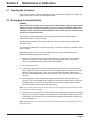
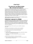
Section 5 Maintenance & Calibration .........................................................................................................................25
5.1 Cleaning the Instrument...........................................................................................................................................25
5.2 Recharging the Internal Battery ...............................................................................................................................25
5.3 Battery Replacement ...............................................................................................................................................26
5.3.1 Internal Battery Replacement.........................................................................................................................26
5.3.2 Lithium Battery Replacement .........................................................................................................................27
5.4 Calibration ................................................................................................................................................................28
Section 6 Troubleshooting ..........................................................................................................................................29
6.1 Power Cables and Connections ...............................................................................................................................29
6.2 Internal Components................................................................................................................................................29
6.3 External Components ..............................................................................................................................................30
6.4 Communications ......................................................................................................................................................30
6.5 Surveyor 4a Software Symbols ................................................................................................................................30
6.6 Error Messages........................................................................................................................................................31
Page 4
Section 1
Introduction
1.1 Unpacking the Instrument
Remove Surveyor 4a from its shipping carton and inspect it for any visible damage. Contact Hach
Customer Service at 1-800-604-3493 if any items are missing or damaged.
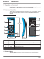
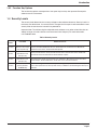
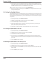
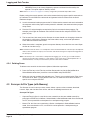
1.2 Instrument Description
The front panel of the Surveyor 4a consists of 11 soft keys and a high-resolution screen. The back
of the case contains the batteries and also has a 9-pin male connector for mulitprobe or PC
connection.
Figure 1 Front Panel
7
SURVEYOR 4a
R
HYDROLAB
8
1
270 mm
(10.62 inches)
9
10
Nickel Metal Hydride
GP Batteries
2
3
4
11
5
POWERED BY HYDROLAB TECHNOLOGY
6
109 mm
(4.3 inches)
12
70 mm
(2.75 inches)
Item Number
Name
Description
1
Screen
The high-resolution, liquid crystal screen displays real-time reading, graphs, or submenus.
2
Function Keys
3
Cursor Keys
4
Power
5
Backlight Key
6
Hidden Key
Takes the action indicated on one of the four rectangles at the bottom of the screen.
Moves the cursor up, down, right, and left in menus, submenus, and virtual keyboards. Hold
down an arrow key to scroll the cursor on the screen in fast repeat mode.
Turns the instrument on and off.
Turns the backlight on and off. The back light allows use in low-light or dark conditions.
Displays system information on the Surveyor 4a and on the multiprobe.
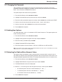
1.3 Screen Features
The screen is divided into three parts. The Real-time parameters, the History Line, and the
function key options.
Introduction
Page 5
Introduction
Figure 2 Screen Features
1
2
3
1.
Real-time Parameters
2.
History Line
3.
Function Key Options
1.3.1 Real-time Parameters
The real-time parameter lines show several parameters and the corresponding real-time readings,
as they are received from the Sonde. The number of lines depends on the parameters selected to
be displayed on the screen. The display automatically switches to a two-column format when the
number of parameters exceeds twelve.
1.3.2 History Line
The dark grey line below the real-time parameter lines is the history line. This shows how the
Surveyor 4a is connected. This line can display six basic messages. The history line messages are
dependent on the types of cable connected to the Surveyor 4a and to the interface mode selected
from the internal setup menu.
Table 1
Message
Description
NoConn
The Surveyor 4a is not connected to a Sonde, charger, or PC.
Series4Sonde
This is displayed if the Surveyor 4a is connected to a Sonde and configured for Series 4 Sondes.
Series3Sonde
This is displayed if the Surveyor 4a is connected to a Sonde and configured for Series 3 Sondes.
Charger
The Surveyor 4a charger cable is connected to the instrument and the Surveyor 4a is powered on.
PC
The Surveyor 4a PC adapter is connected to the instrument and the Surveyor 4a is powered on. The
message will appear even before a physical connection is made.
Terminal
The Surveyor 4a is connected to a Sonde and configured for terminal emulation.
The history line also displays the path selected when moving through the menu and submenu
structure.
Instrument Description
Page 6
Introduction
1.3.3 Function Key Options
The function key options correspond to a front panel key, but they also represent Surveyor 4a
software menus or submenus.
1.4 Security Levels
The security level determines the access privileges to the software submenus. Security Level-2 is
the factory-set default level. If a security level is changed, the Surveyor 4a will remember the new
security level the next time the instrument is powered on.
Important Note: To avoid erasing the mulitprobe main software or any other related data, do not
attempt to log on to Level-3 without assistance from Hach Company. For more information,
call 1-800-604-3493.
Table 2 Security Levels
Security
Level
Password
Allows Access To:
Level-0
Not Required
(Surveyor 4a security
level at power-up)
Power On/Off; Backlight On/Off; Surveyor4 Installed Options Display; Real-time Tabular Data
Screen; Real-time Graph Data Screen; Terminal Screen; Terminal Cursor Movement;
Terminal Cursor Home; Terminal Virtual Keyboard.
Level-1
User Definable
(Disabled on new
Surveyor 4a)
Surveyor4 Files Status; Surveyor4 Files Review; Store; Sonde Files Status; Sonde File
Download; Terminal File Download; Terminal Data Capture.
Level-2
User Definable
(Disabled on new
Surveyor 4a)
Most Surveyor4 Setups; Surveyor4 BP User Calibration; Most Surveyor4 File Functions;
Sonde Setups; Sonde Calibrations; Sonde File Create; Sonde File Delete.
Level-3
User Definable
(Factory Default:
“HYDROLAB”)
Password Change; Factory Installed Options Change; Setup Reset; Parameter History
Reset; File System Reset; Surveyor4 BP Factory Calibration; Downloading New Surveyor4
Software.
Security Levels
Page 7
Visit us at www.hachenvironmental.com
Section 2
Surveyor 4a Setup
Press the OFF/ON key. The temporary welcome display is displayed, followed by the Main Surveyor
4a screen. When received directly from the factory, D/T is the Surveyor time and IBV is its internal
battery voltage.
Complete the following basic setup in NoConn mode.
2.1 Selecting Interface Modes
The Surveyor 4a allows six different interface modes or connections which determine the basic
message displayed on the instrument history line. To select the interface mode, no cables can be
connected to the Surveyor 4a (NoConn Mode).
1. In NoConn Mode, select SETUP/CAL then select SETUP.
2. Highlight Sonde I/F:Mode and press SELECT.
3. Highlight the number that corresponds to the appropriate connection.
•
Select 0 if the Surveyor 4a will be connected to a Series 4 Sonde equipped with a RS232
hardware interface.
•
Select 1 if the Surveyor 4a will be connected to a Series 4 Sonde equipped with a
RS422/RS485 hardware interface.
•
Select 2 if the Surveyor 4a will be connected to a Series 3 multiprobe (DataSonde 3
version 1.20 and higher, Recorder, Reporter, H20, or H20G).
•
Select 3 to interface with Series 3 multiprobes using Terminal mode.
4. Press the DONE key.
5. Make cable connections to the Surveyor 4a.
6. Power the Surveyor 4a on. The history line will reflect the interface mode. For all modes,
except Terminal, the Surveyor 4a will try each baud rate available, starting with highest baud
rate, until it established communications with the Sonde. For Terminal mode, the baud rates
must be manually entered to match the mulitprobe and the Surveyor 4a baud rates to allow
communication. See XXXX for more information selecting baud rates. The history line will
reflect the interface mode.
Note: When the Surveyor 4a connects to a Series 3 Sonde, the Surveyor 4a will reconfigure the following
mulitprobe settings: enables all the parameters; selects conductivity in the conductivity/resistivity column;
selects salinity in the salinity/TDS column, enables conjunctivitis autoranging; enables turbidity autoranging (if
the DataSonde 3 revision is t1.40 or the H20 revision is t2.00); selects %Sat in the %Sat/mg/L column (if
the DataSonde 3 revision is t1.40 and < 1.60, or H20 revision is t2.00 and < 2.10).
2.2 Setting the Time and Date
1. From the Main screen, select SETUP/CAL>SETUP.
2. Highlight Clock using the DOWN cursor key and press SELECT. The Date screen will be
displayed.
3. Enter the new date (MMDDYY). Use the RIGHT and LEFT cursor keys to highlight the numbers
at the center of the screen: 0123456789. When the correct number is highlight press SELECT.
For example, for January 8, 2004 enter 010804.
Surveyor 4a Setup
Page 9
Surveyor 4a Setup
4. Repeat step 3 until the entire date is selected. If a mistake is made, clear entries one by one
using the BACKSPACE key.
5. When the new date is correctly entered, press the DONE key.
6. The Time screen will be displayed. Use the RIGHT and LEFT cursor keys to enter the new time
(HHMMSS). Press DONE when complete. The Surveyor 4a will make a sharp beep noise and
briefly the “Setup Successful! Press any key...” message will be displayed.
7. Press any key to return to the Setup submenu.
2.3 Changing the Date Format
The features specifies the date format that will be used by the Surveyor 4a software.
1. From the Main Screen select SETUP/CAL>SETUP.
2. Highlight Date:Format using the cursor keys and press SELECT.
3. Use the cursor keys and select the date format (0:MMDDYY, 1:DDMMYY, or 2:YYMMDD) and
then press SELECT.
Note: The selection will affect all existing files and all files created or transferred, except captured or
downloaded from Terminal mode.
4. Press DONE when the correction selection is made.
2.4 Setting the Tabular Display Mode
The Tabular display mode is the default mode when the instrument is powered on. The data is
displayed in lines or columns, depending on the size of the characters and the number of
parameters present on the screen.
To add or delete parameter displayed on the screen:
1. From the Main Screen select SETUP/CAL>SETUP.
2. Highlight Display: Tabular using the down cursor key and press SELECT.
3. A screen with the list of parameters is displayed. The parameters currently on the Surveyor 4a
are preceded by numbers. These number provide the order of appearance (from 1 to 24) on
the real-time display lines. The parameter without numbers are not currently displayed on the
Surveyor 4a screen.
4. Select a parameter to display using the UP and DOWN cursor keys and press ADD.
Note: To delete a displayed parameter, select the parameter and press Remove.
5. When all the parameters to be displayed are selected, press DONE. Press GO BACK to return
to the real-time screen (tabular display). The new parameter(s) should be added to the screen.
Note: Some of the parameters, such as temperature, can only be displayed in one unit. For example, if Temp:
°C is added, Temp: °F cannot be displayed. If Temp: °F is added, Temp: °C will be automatically removed.
Changing the Date Format
Page 10
Surveyor 4a Setup
2.5 Setting the Graph Display Mode
The second display mode is a graph. The Graph/Tab key toggles between the tabular and graph
modes.
Due to the different configuration possibilities, one or more parameter may need to be added to the
tabular display to allow the graph mode. See section 2.4 for more information.
1. From the Main Screen, select SETUP/CAL>SETUP.
2. Highlight Display:Graph and press SELECT. A new screen will be displayed with three graph
configuration choices, X-Axis, Y-Axis, and Orientation.
X-Axis Configuration
a. Highlight X-Axis and press Select.
b. Select the Date and Time or one of the parameters and press select.
2.6 Setting the Automatic Shutdown
The automatic shutdown is used to save battery life in case it is not turned off after an operation.
This feature will turn the Surveyor 4a off if no key is pressed in the programmed amount of time
following the last key pressed. Once the Surveyor 4a shuts down, power it back up using the
OFF/ON key.
1. From the Main Screen, select SETUP/CAL>SETUP.
2. Highlight Timeout:Shutdown using the cursor keys and press SELECT.
3. A Timeout:Shutdown screen is displayed.
4. Enter the shutdown timeout. Select 0 (zero) to disable or select the appropriate amount of time
(1–255 minutes) for the specific operation using the RIGHT and LEFT cursor keys. Press
SELECT after each number.
Note: If a mistake is made, clear entries one by one using the BACKSPACE key.
5. When all the numbers are entered, press the DONE key. A “Setup:Successful! Press any key”
message will be displayed.
2.7 Setting the Screen Saver Option
This is a power saving feature that puts the Surveyor 4a screen to sleep if no key is pressed in a
programmed amount of time following the last key pressed. If the screen shuts down, press any
key once and the screen will reappear with the last screen displayed.
If the screen save option is active while using the Surveyor 4a, up to 80% more battery life can be
saved.
1. From the Main Screen, select SETUP/CAL>SETUP.
2. Highlight Timeout:Display using the cursor keys and press SELECT.
3. The Timeout:Display screen is displayed.
Setting the Graph Display Mode
Page 11
Surveyor 4a Setup
4. Enter when the screen save mode will become active. Select 0 (zero) to disable the screen
saver mode or select the appropriate time (10 to 255 seconds) for the specific operation using
the RIGHT and LEFT cursor keys. Press SELECT after each number.
Note: If a mistake is made, clear entries one by one using the BACKSPACE key.
5. When all the numbers are entered, press the DONE key. A “Setup:Successful! Press any key”
message will be displayed.
2.8 Setting the Backlight Feature
The backlight feature turns off the backlight after a certain duration of time. This feature conserves
power in case the Surveyor 4a is not manually powered off. If the backlight auto-shutoff feature is
activated while using the Surveyor 4a, up to 40% more battery life can be saved than if the option
was disabled.
1. From the Main Screen, select SETUP/CAL>SETUP.
1. Highlight Timeout:Backlight using the cursor keys and press SELECT.
2. The Timeout:Backlight screen will be displayed.
3. Choose the shutdown interval, in seconds (1–255) using the cursor keys, and then press
Select. Select 0 (zero) to disable this feature.
4. Press Done. A “Setup Successful!” message will appear, press any key to continue.
2.9 Setting the Baud Rate for the PC
1. From the Main Screen, select SETUP/CAL>SETUP.
2. Highlight Baudrate:PC using the cursor keys and press SELECT.
3. The Baudrate:PC screen will be displayed.
4. Use the cursor keys and the SELECT key to enter the baud rate that the computer uses to
communicate with the instrument.The baud rate is dependent on the communications program
that is used.
5. Press the DONE key when complete.
2.10 Setting the Baud Rate for the Surveyor 4a
1. From the Main Screen, select SETUP/CAL>SETUP.
2. Highlight Baudrate:Terminal using the cursor keys and press SELECT.
3. Use the cursor keys and the SELECT key to set the Surveyor 4a baud rate (300, 1200, 2400,
4800, or 9600).
4. Press the DONE key when complete.
Setting the Backlight Feature
Page 12
Surveyor 4a Setup
2.11 Changing the Password
The password can be changed to limit access to certain Surveyor 4a functions. The current
password is required to change the password. From the factory, the default security is disabled for
levels 1 and 2 and set to “HYDROLAB” for level 3.
This option requires the Level-3 security password.
1. From the Main Screen, select SETUP/CAL>SETUP.
2. Highlight Password:Change using the cursor keys and press SELECT.
3. Enter the Level-3 password using the cursor keys and the SELECT key, and then press DONE.
4. Use the cursor key to select the security level (Level-1, Level-2, and Level-3).
5. Use the cursor keys and the SELECT key to enter the new password.
6. Press DONE when complete.
2.12 Adding New Options
This adds new options, such as a barometer or GPS, to the Surveyor 4a. This option requires the
Level-3 security password.
1. From the Main Screen, select SETUP/CAL>SETUP.
2. Highlight Factory:Options using the cursor keys and press SELECT.
3. Enter the Level-3 password and press DONE.
4. Highlight Barometer/GPS and press Select.
5. Enter which options to install (0=None, 1=BP only, 2=GPS only, or 3=BP and GPS).
Note: The software options need to match the installed hardware (if a GPS card is not installed, do not install
GPS). Failure to so can provide misleading data.
2.13 Selecting the Radix within a Numeric Value
The features allows the selection of radix (a decimal point or comma) within a numeric value. It
also allows the selection of the corresponding delimiter (what will separate the values within a file
during spreadsheet-importable file transfer). For example, decimal point (24.2) or a comma (24,2).
1. From the Main Screen, select SETUP/CAL>SETUP.
2. Highlight Radix:Delimiter using the cursor keys and press SELECT.
3. The Radix:Delimiter screen will be displayed.
4. Select 0, 1, or 2 for the type of radix using the cursor keys, and then press SELECT.
•
0—for decimal point radix and a comma delimiter (0: ‘.’ and ‘, ‘)
•
1—for decimal point radix and a tab delimiter (1: ‘.’ and tab)
•
2—for comma radix and a tab delimiter (2: ‘,’ and tab)
5. Press DONE when complete.
Changing the Password
Page 13
Visit us at www.hachenvironmental.com
Section 3
Sonde Setup
The Surveyor 4a can setup the Sonde (Series3 or Series4, only). The items displayed in the
Sonde Setup submenu depends on the Sonde connected to the Surveyor 4a. Some of the choices
and options are not available on some Series 3 Sondes. See the Series 3 Operating Manual for
more information on setup.
Security Level-2 is required to change Sonde Setup features.
1. Connect the Surveyor 4a to a Sonde.
2. Press the OFF/ON button.
3. From the Main screen, select SETUP/CAL>SETUP>SONDE. The Sonde Setup submenu will be
displayed.
4. Highlight the option to be configured. Sections 3.1—3.9 describes the Sonde Setup submenu
features.
3.1 Selecting Parameters
This feature allows the setup of parameter setup options for the Sonde. The Surveyor 4a will
display the parameters included on the Sonde.
3.2 Turning the Circulator On/Off
Note: When using a DataSonde 3 or Recorder, this option allows the “stirrer” to be turned on of off.
1. Highlight Circltr:ON/Off and press SELECT.
2. Choose to turn the circulator on or off using the cursor keys and the SELECT key. Select 0
(zero) to disable the circulator or select 1 to enable the circulator.
3. Press DONE when complete.
3.3 Turning the Audio On/Off
Note: When using a DataSonde 3 or Recorder, this option allows the “Buzzer” to be turned on of off.
1. Highlight Audio:On/Off and press SELECT.
2. Choose to turn the audio on or off using the cursor keys and the SELECT key. Select 0 (zero) to
disable the audio or select 1 to enable the audio.
3. Press DONE when complete.
3.4 Assigning the SDI-12 Address
1. Highlight SDI:Address and press SELECT.
2. Enter the SDI address using the cursor keys and the SELECT key. The SDI address status is
displayed on the bottom right-hand corner of the screen.
3. Press DONE when complete.
Sonde Setup
Page 15
Sonde Setup
3.5 Setting the SDI Delay
1. Highlight SDI:Delay and press SELECT.
2. Enter the delay of the SDI address (5–994 seconds) using the cursor keys and the SELECT
key.
3. Press DONE when complete.
3.6 Assigning a Site ID
This feature will assigns a description of the site where the Sonde is located.. The Site ID uses a
maximum of 15 letters, numbers, and blanks.
1. Highlight Site ID and press SELECT.
2. Enter the new Site ID using the cursor keys and the SELECT key. To add space, highlight
<<<Space>>> and press SELECT. To delete an error, press the BACKSPACE key.
3. Press DONE when complete.
3.7 Assigning the MODBUS Address
1. Highlight MODBUS:Address and press SELECT.
2. Enter the new Modbus address (1–247) using the cursor keys and then the SELECT key.
3. Press DONE when complete.
3.8 Setting the Sonde Time and Date
Note: When using a DataSonde 3 or Recorder, this option is displayed as “D/T:MDY/HMS”.
1. Highlight Date-Tim:MDY/HMS and press SELECT.
2. Set the date (month, day, year) and time (hours, minutes, seconds) for the Sonde using the
cursor keys and the SELECT key.
3. Press DONE when complete.
3.9 Turning the AutoLog On/Off
1. Highlight Autolog:On/Off and press SELECT.
2. Choose to turn the circulator on or off using the cursor keys and the SELECT key. Select 0
(zero) to disable the autolog or select 1 to enable the autolog.
3. Press DONE when complete.
Setting the SDI Delay
Page 16
Section 4
Logging and Data Transfer
4.1 Introduction
The Surveyor 4a memory logging system comes in several options. The instrument logging
capacity depends on the size of the memory installed. Memory is available in the following sizes:
"Clipboard" memory which allows 12 manually stored scans (up to 300 manually entered
readings), memory which allows approximately 120,000 readings, or memory which allows
approximately 375,000 reading.
4.2 Clipboard Memory
If the Surveyor 4a has Clipboard memory, up to 12 scans (with a maximum of 25 parameter
readings per scan) by using the Store function. This feature captures lines of data displayed at the
time the Store key is pressed.
4.2.1 Storing Clipboard Memory
1. In NoConn mode, select Setup/Cal>Setup>Tabular:Display and press Select.
2. Select the parameters that will be saved to the Surveyor 4a Clipboard memory using the Add
or Remove key.
3. Press the DONE key and then the GOBACK key three times.
4. Press the Store key. One scan has been saved to the Surveyor 4a memory.
5. If a "Clipboard is full!" messages is displayed, refer to
4.2.2 Reviewing Clipboard Scans
1. From the Files>Clipboard (for NoConn, PC, or Terminal modes) screen or the
Files>Surveyor4a>Clipboard screen (for Series3Sonde or Series4Sonde modes), press
SELECT to display a the scan saved to the Clipboard memory when the Store key was
pressed.
2. Depending on the number of scans the Clipboard contains, press the DOWN key and move to
the other files to review the information.
3. Press the DONE key when finished viewing the data.
4.2.3 Transmitting Scans
1. Connect the instrument to a computer using the Surveyor 4a to PC adapter. Power the
Surveyor 4a.
2. Press the Files key.
3. Move the cursor to Transmit and press Select.
4. Select one of the three transfer choices: ASCII: Text, XMODEM: Text, or XMODEM: Binary.
•
ASCII: Text will transfer the stored scans as text, using the ASCII communications
protocol.
•
XMODEM: Text will transfer scans as a spreadsheet-importable text files, using XMODEM
communications protocol.
Logging and Data Transfer
Page 17
Logging and Data Transfer
•
XMODEM: Binary is for factory diagnostic purposes and should not be used by the
operator. This option requires Security Level 3.
Note: Refer to section 2.13 on page 9 to correctly configure the spreadsheet-importable format.
Before starting the transmit process, refer to the communications program specific commands or
to ProComm Plus for DOS basic commands or Hyperterminal basic command in the Quick
Reference chapter.
5. Launch the communication program on the PC. Make sure the correct baud rate is selected for
the computer and that the proper transfer protocol is selected in the communications program
setup menus.
6. From the PC, select the option to receive the files in the communications program. For
example, press PgDn for ProComm Plus for DOS. Name the file and press ENTER. Then
press any key.
7. The last two lines (with zeros) on the Surveyor 4a screen should start changing to show that
the transfer is taking place. Otherwise, check the cables, setup, and transfer procedures.
Press ABort to terminate the transfer.
8. When the transfer is complete, go to the computer directory where the files was saved. Open
the files to view the scan(s).
Note: Information from the Series 3 or 4 mulitprobes cannot be downloaded since the Surveyor 4a Clipboard
memory does not have the capacity to receive files. Call Technical Support to inquire about upgrades to
the Surveyor 4a.
Note: If the Surveyor 4a is connected to a multiprobe with logging, you can also go yo Sonde instead of
Surveyor 4a from the Files submenu to create, delete, or look at the status of the multiprobe files. To
download and file, a Surveyor 4a with memory must be sued. Refer to XXXXX
4.2.4 Deleting Scans
To delete scans stored in the instrument clipboard, follow the steps below.
1. Press the Files key, or the Files key and then Surveryor4a key (for the Series4Sonde or
Series4Sonde connections), move the cursor to Delete and press SELECT.
2. Make sure you want to delete the selected scans. There is not an undo function. Either leave
the cursor on All: Date—Time to delete all the scans, or move the cursor down to select a
specific scan and press SELECT.
4.3 Surveyor 4a File Types (with Memory)
The Surveyor 4a can be set up to store, create, delete, capture, review, annotate, download,
transmit, wipe, and view the status of files, and turn the Autolog feature on or off.
Surveyor File Types
•
Captured Text: this files is a text file that was created, then data was added manually by
pressing the STORE key in NoConn, Series3Sonde, or Series4Sonde mode. Once transferred
to a PC, the captured text can be opened in a word processing program.
•
Manual File: this files was created using a Series 3 multiprobe in Series3Sonde interface
mode. Once transferred to a PC, a manual file can be opened in a word processing or
spreadsheet program.
Surveyor 4a File Types (with Memory)
Page 18
Logging and Data Transfer
•
Time-triggered File: this files is logging events that were created, then added data based on
time intervals. Once transferred to a PC, the time-triggered files can be opened in a word
processing or spreadsheet program.
•
AutoLog File: this files an automatic back-up logging event that was created/activated. Once
transferred to a PC, an auto-log files can be opened in a word processing or spreadsheet
program.
•
Download Text: this file is a text file that was transferred/downloaded to the Surveyor 4a using
a Series 3 multiprobe in terminal interface mode. Once transferred to a PC, a downloaded text
file can be opened in a word processing program.
•
Downloaded File: this files is a multiprobe files that was transferred/downloaded to the
Surveyor 4a using a Series 3 or Series 4 muliprobe in Series3Sonde or Series4Sonde
interface mode. Once transferred to a PC, a downloaded file can be opened in a word
processing or spreadsheet program.
1. From the top level screen, press Files.
2. Press the Surveyor4a key (skip this step if PC or Terminal interface modes are active).
3. Move the cursor to select annotate, create, status, review, wipe, delete, or autolog and press
SELECT.
Note: In PC mode, Transmit (to transfer files from the Surveyor 4a to a PC) is added to the menu. In terminal
mode, Download (to transfer files from the Series 3 multiprobe to the Surveyor 4a) and Capture (to capture
ASCII data from a Series 3 multiprobe) are added to the menu. Capture is also a Create submenu item in
NoComm and PC modes.
4.3.1 Storing Data
To be able to store data to a file, a files needs to be created in the Surveyor 4a memory, otherwise
a "No Log Files available!" message will be displayed. To create a files, refer to section 4.3.2.1 on
page 19.
1. Go to the Series4Sonde screen and press the STORE key.
2. Either select Manual File (if more than one is available) and press select, or press SElect. Note
that the Surveyor 4a will, by default, select the last manual file where data was stored. The
data on the screen is stored to the selected file.
3. Repeat to store more data to the select file or another manual file, if available. The # bytes field
will changes as data is added to the file.
4.3.2 Creating a File
A file can be created within the Surveyor 4a. Up to 24 files can be saved the Surveyor 4a memory
(23 manual or time-triggered files and 1 Autolog file). If the directory is full, following the directions
in XXX
4.3.2.1 Manual File Creation
1. From the Series4Sonde>Files>Surveyor4 screen, move the cursor to Create and press the
SELECT key.
Surveyor 4a File Types (with Memory)
Page 19
Logging and Data Transfer
2. Select Manual or Time-Trig. If Manual is selected, the Surveyor 4a logging software will create
a files manually to store scans of data. If Time-Trig is selected, a files will automatically start
and stop acquiring data as specified by the user.
3. Use the cursor keys and the Select key to enter the file name. Press the Done key when
finished entering the file name.
4. If Time-Trig is selected,
a. Enter the file starting date and press DONE.
b. Enter the Starting time and press DONE.
c. Enter the Stop date and press DONE.
d. Enter the Stop time and press DONE. If you enter an incorrect date or time, a "Start must
be before Stop!" or "Invalid or incomplete text" message will appear. Press any key and go
back to check the time and date and enter the acceptable value.
e. Enter the time (in hours, minutes, and seconds) for the interval between each parameter
reading. The interval must be 30 seconds or more. If an interval below 30 seconds is
entered, the "Entry is outside acceptable limits!" will be displayed at the bottom of the
screen. Press any key and enter an acceptable interval. Press the DONE key when
complete.
f.
Enter the multiprobe warm-up time. The warm-up time is the time it takes the multiprobe
sensors to be ready to record accurate data. Warm-up time will vary according to the
sensors being used and the field conditions. The value must be 30 seconds or more.
When complete, press the DONE key.
5. A screen of parameters appears with the default selection that the matches the Surveyor 4a
tabular display. Parameters can be added and removed. When the new display is configured,
press DONE, and the message file "Files Created!" will briefly appear on the screen. Press
any key to return to the Files>Create window. Note that the additions or removals from the
parameter menu do not affect the tabular display.
If the Surveyor 4a files directory has reached full capacity (24 files and 1 for AutoLog), a "Directory
is FULL!" screen will appear. Press any key.
4.3.3 Creating a Capture File
If the Surveyor 4a is connected to a Series 3 Sonde and Terminal interface mode is being used, file
creation has an additional submenu item, called Capture. This option captures ASCII data from a
Series 3 Sonde, much like PC terminal emulators. Capture is available in NoConn and PC modes,
however, data can only be sent to the capture file in Terminal mode.
1. In Terminal mode, select Files.
2. Select Create and press Select.
3. Select Capture and press Select.
4. Enter the file name of the capture file. Press DONE when complete.
4.3.4 Checking the File Status
1. From the Files>Surveyor 4a menu, highlight Status and press Select. A screen appears that
provides information about the number of files present in the Surveyor 4a directory, the
Surveyor 4a File Types (with Memory)
Page 20
Logging and Data Transfer
maximum number of files that can be stored in the instrument, amount of formatted memory
installed on the Surveyor 4a, the memory currently available, and number of days available
with the present amount of memory left, internal battery capacity (IBC) in percent and in days
left before the Surveyor 4a power runs out, and the external battery capacity (XBC).
Note: The formatted memory capacity is less than the raw memory capacity. To determine raw memory,
press the hidden Hydrolab key.
2. Press any key to return to the Surveyor 4a Files submenu and move to the next option.
To check individual file status, highlight Delete and press SELECT. All files will appear listed with
the file type and the corresponding size. Press the GOBACK key to prevent deleting any file.
4.3.5 Reviewing a File
This function shows the contents of any manual, time-triggered, or AutoLog file. This function can
also be used to the check the status of these file types.
1. From the Files>Surveyor 4a menu, in Series4Sonde interface mode, press the Review key.
2. Choose the file to review and press the Select key.
3. Select how to review the contents of the file, either from top (Beginning) or from a specific date
and time.
a. If Beginning is selected, the information contained in the file is displayed in tabular format.
Press the DOWN arrow key to go to the previous scans.
b. If Date/Time is selected, enter the date where you want to review the data and press
DONE. The default date is the file setup date.
c. Enter the time where you want to start the review and press DONE. The default time is the
file setup time.
d. Press the UP or DOWN arrow keys to move through the file.
4. To return to the Beginning/Date/Time submenu, press GOBACK. TO go back to the Review
menu, press DONE.
4.3.6 Annotating a File
On files have been created, comments can be added to the files. Annotate will only allow
comments to be added to manual, time-triggered, or AutoLog files.
1. From the Files from the Main Menu, in Series4Sonde interface mode, press Annotate.
2. Choose the file to annotate and press SELECT.
3. Enter any comments (up to 80 characters) and press the DONE key when complete.
4.3.7 Deleting Files
Deleting files will make more room for new files and erase unwanted stored files in the instrument
memory.
1. Select Files from the Main Menu.
2. Highlight Delete and press SELECT.
Surveyor 4a File Types (with Memory)
Page 21
Logging and Data Transfer
3. Highlight the file to be deleted and press SELECT.
4. Select 1: Yes to delete the file. A message screen will appear showing the file has been
deleted.
4.3.8 Erasing Manual-triggered Files
This function erases the connects of any manual-triggered files saved in the Surveyor 4a memory.
It only keeps the file name and the parameter settings, and resets the date to the day when the
contents were erased from the file. This function quickly deletes information in the manual files but
leaves an empty file template for future operations. This function only applies to manual files.
1. Select Files from the Main Menu.
2. Highlight Wipe and press SELECT.
3. Highlight the file you want to erase and press SELECT.
If AutoLog is enabled, the file description 0:=> AUTOLOG <= appears on top of the screen. If
AutoLog is disables, the file description will change to =>Disabled File<=. If the AutoLog feature is
resumed, the AutoLog file initially created is enabled, and all new data is added to the same 0:=>
AUTOLOG <= file.
Note: To delete the AutoLog file form the Surveyor 4a memory, disable the Autolog file before removing it
using the Delete option. If an enabled AutoLog file is deleted, the Surveyor 4a will delete it an recreate a new
one.
Note: Make sure the multiprobe is connected to the Surveyor 4a before using the AutoLog feature.
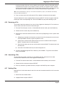
4.3.9 Transmitting a File for the Surveyor 4a to a Computer
This transmission configuration involves connecting the Surveyor 4a to the computer with the
Surveyor 4a to PC adapter cable. Files should be saved in the memory, either created from logging
with a Sonde, captured when connected to a Series 3 Sonde, or transferred (downloaded) from a
Sonde.
4.3.9.1 Time-Trig, Manual-Trig, and Download File Transmission
Note: If transferring files downloaded from a Series 3 Sonde into a Series 4 Sonde, and temperature as a
parameter was selected, both °C and °F will be included in the file. If SpCond:mS/cm was selected,
SpCond:μS/cm, Res, and TDS are included the file. If Depth was selected, both Depth:Meters and
Depth:Feet will be included in the file. If DO%Sat was selected, both DO:%Sat and BP:mmHg will be included
in the file. After the transfer process to the PC is complete, open the file within the PC and erase the
unnecessary parameters and readings. Not e that only the first 80 columns of the file transfers to the
computer.
1. Launch the communications program and make sure the baud rate for the computer and the
proper transfer protocol is selected in the communications program setup menus.
Note: The delimiter and radix will influence the way the file is transferred.
2. Select Files from the Main Screen.
3. Highlight Transmit and press SELECT.
4. Highlight the file to be transmitted and press SELECT.
5. Highlight Printer-Ready, SS-Importable, or XMODEM:Binary and press SELECT.
Surveyor 4a File Types (with Memory)
Page 22
Logging and Data Transfer
•
Print-Ready will send the file to a printer or create a text file.
•
SS-Importable will create a spreadsheet-importable file.
•
XMODEM:Binary if for factory diagnostic purposes only.
If Printer-Ready is select:
a. Choose the type of statistics which will append to the print-ready output. Select NoStats,
Daily Stats, Total Stats, or Both Stats and press SELECT.
•
NoStats—
•
Daily Stats—Information on about the files statistics for each day will be sent to the printer
and/or capture file. Information regarding the number of readings, the minimum value and
the time it was recorded, the maximum value and the time it was recorded, the maximum
change between two points and the time it was recorded, the mean, and the standard
deviation for the day’s data will be displayed.
•
Total Stats—Information is similar to Daily Status, except Total Stats provides the overall
statistics over the entire logging run.
•
Both Stats—Daily and overall statistics are calculated.
b. Turn the printer on or open a capture file. Then press any key.
c. A transfer process screen will appear on the Surveyor 4a screen to show the file transfer is
taking place.
d. After the transfer is complete, a "Deactive printer and/or close capture file" message will
appear.
e. Turn the printer off or close the capture file.
Note: At the bottom of the file, a "Recovery finished line" will be displayed.
If SS-Importable Transmission is selected:
a. After selecting SS-Importable, a "To start XMODEM transfer...Press any key..." message
will be displayed. Press any key to continue.
b. Follow the communication software prompts. Press ESC on the computer keyboard or the
Abort key form the Surveyor 4a to cancel the file transfer.
c. When the file transfer is complete, a "Transfer completed!" message will be displayed.
Press any key to continue.
d. To view the transmitted file, go to the computer directory where the file was saved and
open the file.
4.3.9.2 Captured and Downloaded Text Transmission
Note: Prior to starting the transmit process, please refer to your communications program specific
commands.
1. Select Files from the Main Menu.
2. Highlight Transmit and press SELECT.
3. Highlight the captured text file and press SELECT.
4. Select ASCII: Text, XMODEM: Text, or XMODEM: Binary.
Surveyor 4a File Types (with Memory)
Page 23
Logging and Data Transfer
•
ASCII: Text will transfer the stored files as straight text files.
•
XMODEM: Text will also transfer files as text files, using the XMODEM communications
protocol.
•
XMODEM: Binary is for factory diagnostics only.
5. Launch the communications program and make sure the baud rate for the computer and the
proper transfer protocol is selected in the communications program setup menus.
6. Select the appropriate downloading process sequence and press any key on the Surveyor 4a.
7. When finished, press any key on the Surveyor 4a.
4.4 The Multiprobe Files Submenu
4.4.1 Creating a File
Note: If creating files with a Series 3 Sonde, and temperature as a parameter was selected, both °C and °F
will be included in the file. If SpCond:mS/cm was selected, SpCond:μS/cm, Res, and TDS are included the
file. If Depth was selected, both Depth:Meters and Depth:Feet will be included in the file. If DO%Sat was
selected, both DO:%Sat and BP:mmHg will be included in the file. After the transfer process to the PC is
complete, open the file within the PC and erase the unnecessary parameters and readings. Not e that only
the first 80 columns of the file transfers to the computer.
1. In Series3Sonde or Series4Sonde mode, press Files and press Sonde. In Series3Sonde
mode, the Surveyor 4a will scan for the Sonde.
2. Highlight Create and press SELECT.
3. Press SELECT again.
4. Enter a file name, a file starting time date and time, a file stopping date and time, an interval, a
warm-up time, an audio (or buzzer), a circulator (or stirrer), and a choice of the parameters to
be recorded.
The Multiprobe Files Submenu
Page 24
Section 5
Maintenance & Calibration
5.1 Cleaning the Instrument
Clean the case, screen, and other components (except connectors and plugs) with a slightly wet
cloth or cotton swab. Use soap to remove grease spots.
5.2 Recharging the Internal Battery
DANGER
Never connect the Surveyor 4a to a power source which exceeds 15 volts or fatal electrical
shock may occur. To avoid shock hazards, do not use AC (110 and 220 VAC 12VDC power
adapters) to power the Sonde. Use battery power when deploying a Sonde outdoors. If an
AC power is used, a Ground Fault Interrupt (GFI) device must be used. GLI installation must
be done by a licensed electrician.
The Surveyor 4a must be powered on (with charger cable and a power adapter properly
connected) and left on in order to charge.
We recommend charging the Surveyor 4a when the instrument internal battery voltage (IBV)
reaches 6.5 volts.
The recharge time depends on the percent left (IB%) in the battery. Charging is complete in three
and a half hours.
When the Surveyor 4a is first received, we recommend that a complete discharge cycle is
performed and then recharge the Surveyor 4a.
1. Connect the Surveyor 4a charger cable to the Surveyor 4a. Attach the 110 or 220 power
adapter to the other end of the charger cable. For the 220 power adapter, connect the
country’s corresponding power cord to the IEC 320 connector.
2. Turn the Surveyor 4a on.
3. A low external power supply screen will be displayed if the Surveyor 4a is connected to an
external power source that is providing insufficient voltage or poor connections where made.
Recheck all connections and try again. Insert the loose end of the power adapter to the
country’s corresponding power cord into the wall outlet. Press any key on the Surveyor 4a to
continue.
4. After the welcome screen, the following screen will be displayed. The Estimated Time to
Charge (ETTC) and estimated current charge level of the internal battery back in percent will
be displayed (IB%). The ETTC value will decrease as the full charge approaches. The IB%
value will change until it reaches fill recharge capacity.
Note: IB% is an estimate. Do not disconnect the Surveyor 4a from charging until prompted. Early disconnect
can severely reduce the operating time.
5. The battery will automatically start to recharge. Press the Suspend key to pause the recharge
process. Press Resume to restart the recharge process. During the recharge process, some
of the original data will reset. Press the All Stats key to provide more detailed information on
the recharge process.
Note: When the All Stats key is selected, it will be replaced with the Est Only key, which brings back the first
charge mode menu.
Maintenance & Calibration
Page 25
Maintenance & Calibration
Table 3 All Stats Information
Display
Description
't
The elapsed time from the beginning of the charging event. Charging stops when 't exceeds approximately three
and a half hours.
Vpeak
The maximum voltage at any time during the charging event.
–'V
The negative change of voltage (Vpeak minus current voltage reading). Charging stops when –'V exceeds 60 mV.
'TCO
The change in temperature from the beginning of the charging event to the current time. Charging stops when
'TCO exceeds 15 °C.
Init
Initial readings when the charge event was started.
Current
Current reading.
Parameters
Time, temperature, voltage (Volts), and battery charge capacity (%)
6. The Surveyor 4a will display “Charging Complete! Disconnect Charger for Normal Operation.
Press any key...” when the charge event is complete.
Note: Charging is not complete when ETTC=0 or IB%=100. Charging is complete when 't equals or exceeds
three and a half hours, –'V equals or exceeds 60 mV, or 'TCO equals or exceeds 15 °C.
7. When IBP is fully recharged, disconnect the Surveyor 4a charge cable. The Surveyor 4a
screen will display the NoConn message.
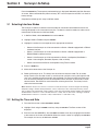
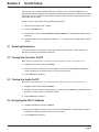
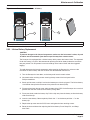
5.3 Battery Replacement
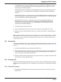
5.3.1 Internal Battery Replacement
CAUTION
To prevent damage to internal components, avoid placing the battery next to a
water source.
Replace the batteries on a clean, dry working surface.
1. Disconnect any cable connections to the Surveyor 4a.
2. Turn the Surveyor 4a upside down on the working surface.
3. Unscrew the four retaining screws with a Phillips screwdriver. Do not pull the screws
completely out.
4. Lift and remove the back panel from the bottom of the Surveyor 4a.
5. Remove the old batteries from the compartment.
6. Insert the new battery, aligning the notches on the battery with the notches on the Surveyor 4a
case.
7. Lightly coat the o-ring around the battery compartment with silicone grease. Do not use any
other kind of grease.
8. Place the back panel over the battery compartment and screw the retaining screws. Do not
overtighten the screws.
Battery Replacement
Page 26
Maintenance & Calibration
Figure 3
Removal and Installation of Battery
4
1
3
2
1.
Battery Compartment/Back Panel
3.
Battery Connector
2.
Phillips-head screws (4) captive
4.
Surveyor 4a Battery Terminal
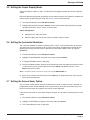
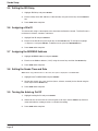
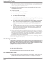
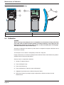
5.3.2 Lithium Battery Replacement
CAUTION
To prevent damage to the internal components, make sure the instrument is clean, dry and
all cables are disconnected. Open the Surveyor 4a away from a water source.
The Surveyor 4a is equipped with a lithium battery which powers the internal clock. The expected
life for this battery is 2 years. We recommend replacing the lithium battery before the end of the
two-year period. This will prevent inaccurate readings of the internal clock and time-triggered
logging.
To avoid damage to the internal components when opening the Surveyor 4a, make sure the
instrument is clean and dry and that all cables are disconnected from the unit.
1. Turn the Surveyor 4a face down, so the front panel faces the work surface.
2. Unscrew the four retaining screws securing the top cover of the back panel with a
Phillips screwdriver.
3. Slowly pull the cover, and flip it back on the bottom part of the back panel. The lithium battery
is located on the top left-hand corner of the printed circuit board (PCB).
4. Place one hand over the top cover and the bottom of the PCB. Lift the Surveyor 4a to a vertical
position over the work surface, lithium battery facing down.
5. Place your thumb under the battery clip. Pull the clip away from the battery and let the battery
slide out of the clip.
6. Insert the new battery. Observe polarity. Match the “+” on the battery with the “+” on the
battery clip.
7. Replace the top cover over the PCB, insert and tighten the four retaining screws.
8. Reset the time and date after replacing the lithium battery. Press Setup/Cal, and Setup,
then Clock.
Battery Replacement
Page 27
Maintenance & Calibration
Figure 4
Removing the Lithium Battery
1
3
4
Nickel Metal Hydride
GP Batteries
2
1.
Top Cover/Back Panel
3.
Holder, Lithium Battery
2.
Phillips-head screws (4) captive
4.
Lithium Battery
5.4 Calibration
DANGER
When loosening removable parts from a multiprobe or any instrument, always point those
parts away from your body and other people. In extreme conditions, excess pressure may
build-up inside a housing, causing caps, sensors, or other removable parts to disengage
with force sufficient to cause serious injury.
Surveyor 4a calibration is not necessary, unless there is an option that requires calibration such as
the internal barometer.
The Surveyor 4a can calibrate a multiprobe just like with a computer.
Proper maintenance of all sensors should proceed calibration. Refer to the Sonde user guide for
detailed sensor maintenance procedures.
Security Level-2 is required for calibration.
1. Set the I/F mode to Series 3.
2. Press the Setup/Cal key.
3. Press the Calibrate key.
4. Press the Sonde key. A pop-up screen will displayed.
5. Highlight the parameter to be calibrated and press Select.
6. Follow the Surveyor 4a prompts using the appropriate calibration sections from the
Sonde manual.
Calibration
Page 28
Section 6
Troubleshooting
6.1 Power Cables and Connections
Verify that the Surveyor 4a and the Sonde are properly connected.
Very that the Surveyor 4a and the Sonde are properly connected to the wall power outlet or
external battery if used.
Verify that the input voltage to the Sonde is between 6.5 and 15 volts by adding IBV or XBV to the
screen.
If the Surveyor 4a is drawing its power from its internal battery (IBP), verified the IBV (voltage)
reading on the display and verify that the battery was properly installed. Check the battery polarity
and voltage.
If the Sonde is equipped with an internal battery verify the IBV reading and verify that the battery
was properly installed. Check the battery polarity and voltage.
Table 4
Symptom
Possible Solution
The Surveyor 4a will not power on.
Charge the battery
Check the backlight time out interval.
The Surveyor 4a battery expires quickly.
Check to see if the GPS option was set to be constantly on.
Check the screen shutdown or timeout interval.
6.2 Internal Components
To avoid damage to the internal components when opening the Surveyor 4a, make sure that the
instrument is clean and dray and that all cables have been disconnected.
Check for the presence of water in the unit. If damp or slightly wet, dry thoroughly using a hair
dryer on low heat, a lint-free cloth, or a towel. Determine where the leak occurred and carry out
any repairs if possible.
If these checks do not reveal the problem, try to substitute other instruments, cables, and terminals
to determine the failing component.
For more information, contact Technical Support.
Troubleshooting
Page 29
Troubleshooting
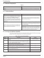
6.3 External Components
Table 5
Symptom
Possible Solution
The Surveyor 4a stirrer or circulator does not operate
correctly.
The Sonde stirrer or circulator needs to be serviced. Refer to the
maintenance chapter in the Sonde User or Operating Manual.
6.4 Communications
Symptom
Possible Solution
For Surveyor 4a software V1.10 and lower, the Surveyor 4a
appears to lock-up if an XMODEM file download is attempted
from Terminal>Files>Download and the attached Series 3
Sonde is not transmitting an XMODEM spreadsheet
importable file. Under these circumstances, the Abort and
power keys are ignored. This situation will only develop if the
Surveyor 4a download starts to initiate the Series 3 Sonde
file download.
To recover from lock-up, disconnect the underwater cable from
either the Series 3 Sonde or the Surveyor 4a, then press Abort or
wait for the transfer to time-out.
Real-time readings from the Sonde are not displayed on the
screen, or symbols instead of readings are displayed after
connecting the Sonde to the Surveyor 4a.
Check the history line to determine how the Surveyor 4a is
connected (NoConn, Series4Sonde, Series3Sonde, Charger, PC,
or Terminal). Depending on the operation to perform, choose one
of the connection types.
Check cables and connections. Check baud rate settings.
Important Note: If you are using 100 meter or longer cable and
decide to switch to 19200, you may lose communications with the
instrument. We recommend connecting the Sonde and Surveyor
4a with a shorter cable before switching the baud rate.
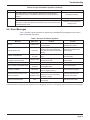
6.5 Surveyor 4a Software Symbols
The software symbols used for the Sonde parameters will also appear on the Surveyor 4a display.
Note that “N/A” will be displayed as “N” on the Surveyor 4a screen.
Table 6 Surveyor 4a Software Symbols
Symbol
Description
Solution
(Blank)
Indicated that the reading is within expected range and does not present any
anomalies.
No service required
#
Indicated that the reading cannot be taken for the parameter, it is out of
range (above or below the Sonde measurement capability). For instance, if
the Surveyor 4a battery voltage is out of range, the instrument will display #
signs on the screen in place of the reading.
—
X
Indicated the Surveyor 4a is interrogating the Sonde for information, or that
the parameter will keep a fixed value and will not update
—
------
Indicates that the Surveyor 4a is interrogating the multiprobe for information,
or that the parameter is not available or off-line (the reading will not update).
—
*
Reminder to set the time after changing the clock battery or parameter has
never been calibrated after a reset.
—
&
After D/T, it indicates that the Surveyor 4a clock is not functioning.
Replace the lithium battery.
After IB% Svr4a:%Left, it indicates that Surveyor 4a battery was removed.
Contact Technical Support.
External Components
Page 30
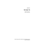
Troubleshooting
Table 6 Surveyor 4a Software Symbols (continued)
Symbol
!
Description
Solution
For version before 1.10 only. when the Surveyor 4a is connected to an
external power source, it indicated that the Surveyor 4a internal battery is
expired.
After D/T, it indicates that the Surveyor 4a clock battery is low.
^
For versions before 1.10, after IB% Svr4a:%Left, it indicates that the
Surveyor 4a battery was replaced or that the Surveyor 4a cannot detect the
estimated battery status.
Recharge the battery.
Replace the battery.
Perform a new discharge and
recharge cycle.
6.6 Error Messages
Table 7 provides a quick reference for general error messages that may appear on the screen
when working with the Sonde.
Table 7 Surveyor 4a Software Symbols
Message
NoConn
Graph parameter N/A
Invalid or incomplete text!
No suitable X-axis Parameter! (or:)
No suitable T-axis Parameter!
Directory is FULL! Press any key...
Entry is outside of acceptable limits!
No memory installed!
External power is less than 11.4V,
Check connections!
*Start must be before Stop!
Menu Tree1
Problem
Solution
The instrument is not connected to
any peripherals.
Check the Surveyor 4a and
peripheral connections.
Graph/Tab
Appears any time the graph mode is
switched when graph parameters
have been removed from the tabular
display.
Add more parameters to the
tabular display.
Date & Time
(or:) Files
Too few characters entered or invalid
entry.
Use the BACKSPACE key and
correct the entry.
No tabular display parameter is
suitable for this axis.
Add more parameters to the
tabular display.
The files directory is full.
Delete one or more files.
An invalid number was entered or an
unacceptable value.
Enter a correct figure.
The Surveyor 4a is not equipped
with any logging memory.
Contact Technical Support.
(History line)
(Charger mode)
The instrument is connected to an
external power source providing
insufficient voltage.
Check the instrument and
peripheral connections.
Files
An incorrect start/stop time/datre
was entered.
Enter the correct values.
(History Line)
Display:Graph
Files
Display:Graph
(or:) Files
Reset:Files
1. Menu tree refers to the general menu where the error message can be found, not the specific place or places where it is displayed.
Error Messages
Page 31
Visit us at www.hachenvironmental.com