1
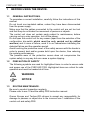
Cat. No. E06-EN-01
Cat. No. E06-EN-01
F3SP-U5P-TGR Series Single Beam Safety Control Unit/Safety Level 4
USER´S MANUAL
Authorised Distributor:
Cat. No. E06-EN-01
Note: Specifications subject to change without notice.
Printed in Europe
F3SP-U5P-TGR Series
Single Beam
Safety Control Unit
Safety Level 4
USER´S MANUAL
F3SP-U5P-TGR
User's manual
Cat. No. E06-EN-01
F3SP-U5P-TGR series
Single beam safety control unit,
safety level 4,
from 1 to 4 pairs of photocells E3FS
USER'S MANUAL
F3SP-U5P-TGR
User's manual
The device conforms with the EC requirements in compliance with the
following standards:
-Low Voltage Directive 73/23/EEC
-EMC Directive 89/336/EEC
-Machinery Directive 89/392/EEC
-IEC 61496-1: 1997
-IEC 61496-2: Ed.2 IEC :2001 (CDV draft8)
-DIN V VDE 0801: 1990 and
-amendment A1: 1994
-EN 61000-2,-3,-4,-5,-6
-EN 55022: 1994
-DIN EN 60204-1: 1993
-EN 50178: 1997
-IEC 664-1: 1997
MANUFACTURER:
TECHNO-GR s.r.l.
via Torino, 13/15
10046 Poirino (TO) - ITALY
Tel.
+39 011 9452041
FAX
+39 011 9452090
USER MANUAL:
Versione 3.0 del 12/06/2003
3
F3SP-U5P-TGR
User's manual
INDEX
1
BEFORE USING THE DEVICE. ......................................................5
1.1
1.2
1.3
GENERAL INSTRUCTIONS. ............................................................................5
PRECAUTION OF SAFETY .............................................................................5
ROUTINE MAINTENANCE...............................................................................5
2
GENERAL INFORMATION AND MAIN APPLICATIONS..............6
3
OPERATION....................................................................................8
4
PRECAUTIONS AND INSTALLATION CRITERIA. .......................9
4.1
4.2
5
CALCULATION OF THE MINIMUM INSTALLATION DISTANCE.....................9
REFLECTIVE SURFACES. ............................................................................10
CONNECTIONS............................................................................ 11
5.1
5.2
5.3
REFERENCES ON THE TERMINAL BOARD.................................................11
PINOUT TOP VIEW ........................................................................................12
WIRING EXAMPLE.........................................................................................13
6
ALIGNMENT PROCEDURE......................................................... 15
7
OPERATING PROCEDURES. ..................................................... 16
7.1
7.2
7.3
7.4
7.5
7.6
DIP-SWITCHES CONFIGURATION...............................................................16
CONFIGURATION OF THE NUMBER OF PHOTOCELLS.............................16
MUTING FUNCTION. .....................................................................................17
7.3.1 DESCRIPTION......................................................................................17
7.3.2 INSTALLATION CRITERIA ..................................................................18
OVERRIDE. ....................................................................................................23
STARTING THE OVERRIDE FUNCTION.......................................................23
MUTING RESTRICTIONS (MUTING FUNCTION)................................................24
8
LED DIAGNOSTIC ....................................................................... 25
9
FINAL CHECKS. .......................................................................... 25
10
ROUTINE MAINTENANCE OPERATIONS. ................................ 26
11
GENERAL INFORMATION AND USEFUL DATA. ..................... 27
12
TECHNICAL DATA. ..................................................................... 28
13
OVERALL DIMENSIONS. ............................................................ 29
14
NOTE ............................................................................................ 30
4
F3SP-U5P-TGR
1
User's manual
BEFORE USING THE DEVICE.
1.1
GENERAL INSTRUCTIONS.
To guarantee a correct installation, carefully follow the instructions of this
manual.
Do not touch non-insulated cables, unless they have been disconnected
from the power supply.
Make sure that the cables connected to the control unit are not too taut
and that they do not hinder the movement of persons or objects.
The control unit does not contain parts subject to maintenance; before
carrying out any outer operation, turn off the power.
Do not open the control unit for any reason (apart from the selection of the
configuration dip-switch which must be only carried out by skilled
workers) and in case of failure, send it to our laboratories indicating the
detected failure and the operation period.
Avoid touching the protective cover of the safety sensors with the hands in
order to prevent dust and/or grease build upon the device, thus reducing
the system performances.
The possible wear of the protective covers does not compromise the
system safety in any way but can cause a system tripping.
1.2
PRECAUTION OF SAFETY
The following symbols are used for highlighted items in order to ensure safe
and proper use of the F3SP-U5P-TGR. Highlighted items are critical for safe
operation and must be heeded at all time.
WARNING
NOTICE
1.3
ROUTINE MAINTENANCE.
Be sure to conduct inspection regularly.
Please refer to sec.10 and the safety PES instruction manual.
Omron Europe and Techno-GR refuses to accept any responsibility for
damage to persons or object due to the incorrect use / installation of the
control unit and safety PES.
5
F3SP-U5P-TGR
2
User's manual
GENERAL INFORMATION AND MAIN APPLICATIONS.
The single beam safety control unit F3SP-U5P-TGR has been designed and
produced to meet the need to protect persons in areas where it is necessary
to guarantee the safety of the operator using machinery, robots or in general
automation systems which are considered dangerous or subject to casual or
undesired access to unsafe parts.
The system conforms with the requirements for safety devices of type 4 in
compliance with international standards, e.g. IEC 61496 1-2.
WARNING
The safety system category depends on the safety PES’s used as follows.
Type 4 safety PES
: Safety system category 4
Type 2 safety PES
: Safety system category 2
• A qualified person, as determined by local regulations, must confirm that
installation, inspection, and maintenance are implemented correctly.
• Do not disassemble, repair, and modify the control unit and safety PES.
The control unit does not contain parts subject to maintenance.
• The presence of a limb or an object interrupting one of the safety PESs
will open the safety outputs and consequently stop the connected
machine. It is necessary to install the safety PESs in such a way that
bypassing and defeating of any person is not possible.
• Do not use the control unit and safety PES on machines that cannot be
stopped by electrical control in case of an emergency.
• Do not use the control unit and safety PES in environments exposed to
flammable or explosive gases.
• Do not use the control unit and safety PES in a retro-reflective
configuration. Otherwise detection may fail.
NOTICE
• Do not install the control unit and safety PES in the following environments;
- Areas exposed to intense interference light such as direct sunlight.
- Areas with high-humidity where condensation is likely to occur.
- Areas exposed to corrosive gases.
- Areas exposed to vibration or shock levels higher than specification
provisions.
• Do not use the cellular phones or transceivers near the control unit and
safety PES.
6
F3SP-U5P-TGR
User's manual
• The control unit and safety PES must not be used in water.
The F3SP-U5P-TGR safety controller is protected by a plastic housing so that
it can be installed on a DIN/OMEGA rail; it has 32 removable screw terminals
to which it is possible to connect from 1 to 4 pairs of photocells.
This version of the single beam safety control unit has the ‘muting’ function
integrated, by means of this function it is possible to connect or disconnect
one or more pairs of photocells in order to allow - for instance - the material
passage without stopping the machine.
The additional ‘override’ function enables system, to keep the output relays
closed even with intruded rays to enable material transport after a system
shutdown.
Both muting and override functions represent a system, that require
additional precautions to limit the reduction of the safety level. This
precautions have to be considered carefully.
The muting and override function is available by simply connecting the F39A11 muting lamp (or similar yellow bulb type lamp for 24VDC / 3W to 5 W)
supplied separately.
The presence of a limb or an object interrupting a beam causes the opening
of the safety outputs and the consequent stopping of the connected machine.
It is necessary for the safety sensors to be connected in the right position in
such a way that there isn’t any possibility to climb over or defeat the system.
Here is a list of the commonly used applications:
◊ Machines for the processing of wood, glass and ceramic products.
◊ Automatic warehouses.
◊ Conveying lines.
◊ Palletizers
The unit has been designed in accordance to the following standards:
IEC 61496-1: 1997.
FDIS IEC 61496-2: 1997.
Safety of machinery: electro-sensitive
protective devices
- General requirements and test.
Safety of machinery: electro-sensitive
protective devices
- Particular requirements for system using
active opto-electronic devices.
7
F3SP-U5P-TGR
3
User's manual
OPERATION.
The electronic control system of the device is made up of a microprocessor.
By means of the suitable hardware, it continuously control and check the
connected photocells. No interference among the photocells is possible as
they are controlled sequentially; it will be thus possible to install one or two
adjacent photocells. When one or more beams are interrupted, the electronic
system opens the outputs.
The photocells have been triggered are displayed by LEDs on the housing.
The control-unit can work in two different modes (please refer to par. 7 page
16) which he can carry out the following operations:
The two external buttons that have to be connected are for:
• TEST : This is used to check if the whole system works effectively. By
pressing the TEST button (opening of the contact), this simulates the
interruption of one or more safety PESs. This operation makes the
machine stop, so the system checks can be made according to the
established time and modes. If pressed after a failure detection of the
unit (see the table error code), reset of the system is required.
• RESET button: It is used to start the system, also for manual reset
condition after relay triggering or after an error which can be reset (see
table related to the error codes).
Two different operating modes are available:
1. Automatic reset: The system will start automatically after the beam
intrusion have been removed.
2. Manual reset: The system will remain in safe off condition until the
RESET button have been pressed. This manual reset allows to start
the system only on a wanted action of the user.
During the unit working, no operation set by the user interface involves
functions which can influence the system safety.
8
F3SP-U5P-TGR
4
User's manual
PRECAUTIONS AND INSTALLATION CRITERIA.
The safety products used must be suitable for the required application,
and other influences must be also taken into account such as a room
temperature, electromagnetic interference, intense light sources etc.
Please refer to the manual for specification or contact the manufacturer for
details.
4.1
CALCULATION OF THE MINIMUM INSTALLATION DISTANCE.
The safety distance ‘S’ must be sufficient to guarantee that the dangerous
area cannot be reached by the operator up to the moment in which the
machine with moving part stops. The safety distance must be calculated
according EN999 (European Standards. Safety of Machinery – The
positioning of protective equipment in respect of approach speeds of part
of the human body).
Using EN 999 formula:
S=(K*T)+C
S
T
K
C
= safety distance.
= T1 + T2
whereas T1 = machine response time in seconds.
T2 = unit response time in seconds including Safety sensor response time.
= 1600 mm/s (speed of the body approaching the dangerous area).
= additional distance depend on resolution of SLC and applicable standard.
1) Multiple separate beams (EN999, clause 6.1.4)
K = 1600 mm/s
C = 850 mm
Heights recommended
in EN999
st
Heights of 1 ray
4 Beams
3 Beams
2 Beams
300 mm
300 mm
400 mm
900 mm
nd
600 mm
700 mm
rd
900 mm
1100 mm
th
1200 mm
Heights of 2 ray
Heights of 3 ray
Heights of 4 ray
2) Single height beam (EN999, clause 6.1.5)
Where the risk assessment allows the use of a single beam, the following values can be used
K = 1600 mm/s
C = 1200 mm
The height of beam from the ground or reference plan: 750mm (EN 999)
9
F3SP-U5P-TGR
User's manual
WARNING.
Always maintain the safety distance between the safety PES and a
hazardous part of a machine.
4.2
REFLECTIVE SURFACES.
In case that reflective surface exist, the distance must be sufficient to avoid
the possibility of passive reflections.
<Top View>
reflective material
RX bar
A
TX bar
2°
2°
2°
Object
2°
A
reflective material
Distance between emitter and
receiver (detection distance L)
0.3 to 3m
Minimum installation distance
D
0.27 m
3m or more
L x tan 2° = L x 0.034 (m)
WARNING.
10
F3SP-U5P-TGR
User's manual
Do not install the safety PES in a location affected by shiny surface
reflections.
5
5.1
CONNECTIONS.
REFERENCES ON THE TERMINAL BOARD.
TERMINAL BLOCK ASSIGNMENT
TERMINAL
OUTER CONNECTION
1–2
Connect to the 24 Vdc power supply, terminal 1 Æ 24Vdc / terminal 2 Æ 0Vdc.
3–4
RESET button; connect a normally opened button (N.O.).
4-5
TEST button; connect a normally closed button (N.C.).
6-7
Connect the muting signaller.
8
Input of the muting B sensor.
Connect to the N.O. contact of the muting sensor (photocell, proximity switch, other).
9
Input of the muting A sensor.
Connect to the N.O. contact of the muting sensor (photocell, proximity switch, other).
10
Input of the muting D sensor.
Connect to the N.O. contact of the muting sensor (photocell, proximity switch, other).
11
Input of the muting C sensor.
Connect to the N.O. contact of the muting sensor (photocell, proximity switch, other).
12
Earth. Connect to the plant’s earth.
13 - 14
(OUT1) safety output 1 with N.O. contact.
15 - 16
(OUT2) safety output 2 with N.O. contact.
17 - 18
Power supply to emitters (TX) of PES 1 and 2. Connect Vs wires (pin 1 of connector) to
terminal 17, and 0V wires (pin 3 of connector) to terminal 18.
19 - 20
Sending test signal to emitters (TX) of the safety PES 1 and 2; Connect test wire (pin 4 of
connector) of PES 1 to terminal 19, and that of PES 2 to terminal 20.
21 - 22
Power supply to emitters (TX) of PES 3 and 4. Connect Vs wires (pin 1 of connector) to
terminal 21, and 0V wires (pin 3 of connector) to terminal 22.
23 - 24
Sending test signal to emitters (TX) of the safety PES 3 and 4; Connect test wire (pin 4 of
connector) of PES 3 to terminal 23, and that of PES 4 to terminal 24.
25 - 26
Power supply to receivers (RX) of PES 1 and 2. Connect Vs wires (pin 1 of connector) to
terminal 25, and 0V wires (pin 3 of connector) to terminal 26.
27 - 28
Receiving PNP output from the receivers (RX) of safety PES 1 and 2: Connect PNP out
wire (pin 4 of connector) of PES 1 to terminal 27, and that of PES 2 to terminal 28.
29 - 30
Power supply to receivers (RX) of PES 3 and 4. Connect Vs wires (pin 1 of connector) to
terminal 29, and 0V wires (pin 3 of connector) to terminal 30.
31 - 32
Receiving PNP output from the receivers (RX) of safety PES 3 and 4: Connect PNP out
wire (pin 4 of connector) of PES 3 to terminal 31, and that of PES 4 to terminal 32.
11
F3SP-U5P-TGR
5.2
User's manual
PINOUT TOP VIEW
BREAK / GUARD
FTC.4
FTC.3
FTC.2
FTC. 1
12
F3SP-U5P-TGR
5.3
User's manual
WIRING EXAMPLE.
Connection of 4 safety PES to the control unit.
GND
Muting Muting
A-B
C-D
MAIN SUPPLY
24 VDC
Muting
sensor
contatcs
N.O.
S
T
A
R
T
T
E
S
T
Safety output 1
F39-A11
Safety output 2
N. N.
A. C.
EXTERNAL
FUSE
Top view
1
2
3
4
5
6
7
8
9 10 11 12 13 14 15 16
F3SP-U5P-TGR PIN Assignment
17 18 19 20 21 22 23 24 25 26 27 28 29 30 31 32
bleu
brown
bleu
black
brown
black
black
black
+
+
-
E3FS Transmitter
-
pnp out
test
E3FS
Receiver
E3FS Transmitter
E3FS Transmitter
E3FS
Receiver
E3FS
Receiver
13
F3SP-U5P-TGR
User's manual
Please, note:
•
•
•
•
•
•
•
•
•
To configure the control unit in such a way that it works only with
three photocells, it is necessary to connect the unused transmitter
output to the corresponding receiver input, in this case to terminal
TEST-TX3 with PNP_OUT-RX3.
All models can be connected in all the possible combinations for a
maximum of four pairs of sensors with at least one pair connected.
The power supply which is necessary to power the system must
conform to standard EN 60742 (double insulation) or with equal
insulation, for instance VDE 0551.
It is necessary to protect the control unit with an outer fuse having a
nominal interruption current equal to 1 A.
The TEST and RESET pushbuttons must be positioned in such a way
that the operator can see the protected area when he restarts, or
carries out a test or override operation.
The Muting lamp (F39-A11) be positioned in a place where it can be
seen from any operative point.
Read the paragraph relating to the muting function and its use for the
positioning of the activation sensors of this function.
Both safety contacts OUT1 and OUT2 must be connected. If the
machine has a single locking circuit, the two normally opened
contacts must be connected in series.
The connection cables of the photocells, of muting request, start and
test must be masked with minimum section 22AWG. The screen
braids must be all earthed towards the control unit side.
14
F3SP-U5P-TGR
6
User's manual
ALIGNMENT PROCEDURE.
After having carried out the correct mechanical assembly and the correct
connections as described in the previous paragraphs, it is necessary to
align the pairs of photocells. Follow the operative modes as follows:
•
•
•
•
•
•
•
•
Turn off the power supplying the control unit.
Open the test contact.
Power the control unit.
Align the photocells by observing the LEDs on the control unit: If the
alignment of the relevant pair of photocell is correct, the LED
corresponding LED will turn on.
After the alignment, turn off the power supplying the control unit,
close the test contact and power the control unit again.
Wait for the control unit to carry out the initial tests.
At the end of this operation, the unit indicates the right alignment
with the guard led green on.
Carry out all the checks described in the final checks and in the
routine maintenance operations.
During aligning operations or normal working, check that the photocells
connected to the same or other units do not interfere which each other.
NOTICE
The control unit can detect the mutual interference between safety PESs. The
control unit forces the output contact to open, when it detects external
disturbance light including mutual interference light.
The safety PESs should be installed the following way to avoid mutual
interference.
- The safety PESs are installed with sufficient distance.
- Emitters and receivers of safety PES are installed alternately as follows:
TX
RX
RX
TX
TX
RX
RX
TX
15
F3SP-U5P-TGR
7
User's manual
OPERATING PROCEDURES.
7.1 DIP-SWITCHES CONFIGURATION.
The configuration indicated in the table must be selected on both the dipswitches available in the front cover.
SW 1
Function
1
X
1
not used
muting A-B act on the sensor couples 1
and 2.
muting C-D act on the sensor couples 3
and 4.
On
muting A-B act on the sensor couple 1.
muting C-D act on the sensor couple 2.
The sensor couples 3-4 continue to
function normally.
function
4
ON
3
3
4
Off
3
1
2
2
Function
2
SW 2
ON
4
function
Off
muting 60 s
Off
manual restoring
On
muting ∞ s *
On
automatic restoring
The control-unit is manufactured from the factory with the following configuration:
• Automatic reset, all four sensors in muting, the maximum duration
of the muting is of sixty seconds.
* infinite muting duration: this feature must be used carefully because it’s
against the norm. Using this, the user must know that it works under its sole
responsibility.
7.2
CONFIGURATION OF THE NUMBER OF PHOTOCELLS.
In case you use a number of photocells which is lower than 4, operate as
follows: to disconnect the photocells do not use and therefore do not connect
to the control unit; carry out a connection among the following terminals:
unused photocell
connection
1
19 to 27
2
20 to 28
3
23 to 31
4
24 to 32
At least one pair of photocells must be connected, otherwise (condition of all
the disconnected photocells) the control unit is locked.
16
F3SP-U5P-TGR
7.3
User's manual
MUTING FUNCTION.
7.3.1 DESCRIPTION.
As mentioned in the introduction, the muting function can be enabled with
any unit by simply connecting the F39-A11 muting lamp when the unit is
switched off.
This presence of this indicator is recognised every time the unit is
powered on. If its presence is detected, the unit will enable the muting
function and if its presence is not detected the unit will ignore any request
for muting. It is important to note that if the muting indicator is connected
during the F3SP-U5P-TGR is powered on, it will not be recognised and
the muting function will not be enabled. Once enabled, if the indicator
develops a fault or is removed without first disconnecting the unit’s power
supply, it will signal an error as described in section 8.
To disable the muting function, the unit’s power supply must be turned on
without the F39-A11 muting lamp connected.
In brief: this function, present on all units, is enabled and disabled by
means of the following simple procedure:
- Disconnect the unit’s power supply.
- Connect the appropriate F39-A11 muting lamp and the muting sensors.
- Restore the unit’s power supply.
Bypass the muting function as follows.
- Disconnect the unit’s power supply.
- Disconnect the F39-A11 muting lamp and the muting sensors.
- Restore the unit’s power supply.
17
F3SP-U5P-TGR
7.3.2
User's manual
INSTALLATION CRITERIA
1. The muting sensors must recognise the material (pallets, vehicles, etc.)
in all its length.
2. The sensors must be arranged in such a way that the material is
recognised even when it must be lifted for the relevant processing.
3. In case of different transport speeds in the muting area, always bear in
mind their influence on the muting total duration.
4. All the safety photocells and the muting sensors must be arranged in
such a way that the previous material has already passed the last
muting sensor before the new material has reached the first sensors.
S3
S2
S1
GOODS 1
B2 A2
GOODS 2
GOODS 3
B1 A1
In the previous page, an installation example of a protection arranged on a
conveyor is drawn; it must allow the passage of package 1, preventing
other packages from passing or it must allow the passage of packages 1
and 2, preventing package 3 from passing. The protection photocells S
are connected to the F3SP-U5P-TGR control unit and are temporarily
interrupted at the package passage by means of the muting A1, A2, B1
and B2 activated sensors.
Sensors A and B are optical, mechanical, proximity, etc. sensors with
closed contact in the presence of the object to be detected.
In both cases, the configuration dip-switch 2 must be set in the on
position.
18
F3SP-U5P-TGR
User's manual
Application with four muting sensors, passage permitted only for package 1:
Muting sensor connection:
24 VDC
contact of A1
L
v
B2 A2
S
B1 A1
N.C.
11 MUTE C
N.C.
10 MUTE D
contact of A2
9 MUTE A
contact of B1
8 MUTE B
d1
F3SP-U5P-TGR
terminals
D
contact of B2
Application with four muting sensors, passage permitted only for packages 1 and 2:
Muting sensor connection:
24 VDC
contact of A1
11 MUTE C
L
10 MUTE D
v
B2 A2
S
B1 A1
contact of A2
9 MUTE A
contact of B1
8 MUTE B
d1
F3SP-U5P-TGR
terminals
D
contact of B2
Application with two muting sensors, passage permitted only for package 1:
Muting sensor connection:
24 VDC
contact of A
B
S
N.C.
11 MUTE C
N.C.
10 MUTE D
9 MUTE A
8 MUTE B
A
d1 = D
contact of B
F3SP-U5P-TGR
terminals
19
F3SP-U5P-TGR
User's manual
where:
D:
minimum distance that the muting sensors keep active the
request; it depends on the parcel length: D < L.
d1:
necessary maximum distance so that the muting request is
accepted; it depends on the parcel speed:
dmax [cm]= v[m/s] * 3[s] * 100
This distance must not allow to activate both sensors and
the muting with the accidental passage of a person.
Application with four muting sensors and only photocell S1:
Muting
signalizer
Start & Test
button
F3SP-U5P-TGR
control-unit
Protect the
cables
Light cable
Power cable
Muting cable
RX cable
TX cable
20
F3SP-U5P-TGR
User's manual
Muting sensor connection:
24 VDC
contact of A1
L
v
B2 A2
S
B1 A1
N.C.
11 MUTE C
N.C.
10 MUTE D
contact of A2
9 MUTE A
contact of B1
8 MUTE B
d1
D
contact of B2
F3SP-U5P-TGR
terminals
The examples above are thought for the use of the muting functions only
relating to sensors S1 and S2, with the configuration DIP-SWITCH 2 in the off
positions; sensors S1 and S2 are controlled by the muting A and B inputs,
while sensors S3 and S4 are controlled by the muting C and D inputs. His
configuration makes other applications be possible.
Application with eight muting sensors and output and input control
We imagine an area in which a manipulator acts; the barriers in input and
output must allow the passage of the packages only when the manipulator
has terminated its work, thus avoiding intrusions in unwished moments.
Trigger zone
of handler
B4 A4
S4
S2
S3
S1
B3 A3
B2 A2
B1 A1
21
F3SP-U5P-TGR
User's manual
Muting sensor connection:
24 VDC
contact of A3
Muting enable to S3 and S4
from robot system control
contact of A4
contact of B3
11 MUTE C
contact of B4
10 MUTE D
9 MUTE A
contact of A1
8 MUTE B
contact of A2
F3SP-U5P-TGR
terminals
contact of B1
contact of B2
•
•
•
•
•
Muting enable to S1 and S2
from robot system control
The TEST and START pushbuttons must be positioned in such a
way that the operator can see the protected area when he carries
out restart, test or override operations.
The F39-A11 muting lamp must be positioned in a place where it
can be seen from any operative point.
If the muting sensors are installed very near the protection
photocells, it is necessary to install the sensor receivers on the
photocell sender side to avoid interference.
The system is anyway protected from possible failures due to the
cable damage; it is necessary to prepare the wiring of all
connections so as to avoid damage to the connection cables.
The control unit must be located in a cabinet with protection
degree of at least IP54.
22
F3SP-U5P-TGR
7.4
7.5
User's manual
OVERRIDE.
This function makes it possible to force a muting condition, if it is
necessary to start the machine despite one or more rays have been
interrupted by the material. The aim is that of removing from the protected
area the material which has possibly gathered before the photocells for
instance because of a failure of the machine cycle.
Let’s suppose that a pallet has stopped before one or more used optical
devices; the conveyor belt cannot be started again because the control
unit - after having detected one or more interrupted rays - will not close the
safety outputs, thus making it impossible to free the controlled area.
By starting the override function, it will be possible to carry out this
operation.
STARTING THE OVERRIDE FUNCTION.
• Switch off the control unit.
• Make sure that the TEST and RESET buttons are connected. (N.C.
for the TEST button, N.O. for the RESET button).
• Switch on the control unit.
• Within 10 seconds, press together the test and reset buttons and
keep pressing. (At each switching on operation, a test is carried out
to check that the buttons are not locked).
• The override function has been activated. The display visualises
three overlapping segments. The muting lamp blinks to signal the
light curtain disconnection.
• The maximum duration of the override function amounts to 60
seconds after that the light curtain is connected again even if the
buttons are pressed. If the buttons are released before this time has
elapsed, the override function will be immediately stopped.
23
F3SP-U5P-TGR
7.6
User's manual
MUTING RESTRICTIONS (muting function).
a) The muting operation must occur according to the correct timing
sequence. For the two muting channels, it is necessary to activate
input MUTE_A or MUTE_C at first and then input MUTE_B or
MUTE_D within 3 seconds. If not, the muting sequence will not be
activated.
b) When the muting state is active, an object can remain for a period of
no longer than 60 s., otherwise the muting function is switched off.
This mechanism is optional and can be deactivated when the control
unit is set up. (see page 13)
c) For the cases in which the muting function is automatically disabled
because of time-out, the request must be cut-out (override function,
or removing object (and restart)) to generate the following correct
muting state.
MUTE_A
30 ms min
MUTE_B
3 s max
ON
MUTE_STATE
OFF
OFF
∞ / 60 s max
It is not possible to carry out a muting request, if the light curtain is interrupted
and the output contacts are in the opened.
24
F3SP-U5P-TGR
8
User's manual
LED DIAGNOSTIC
Information of the units operative state by means of four LEDs.
The LED state has the following meaning:
• GREEN LEDs: if switched on, the photocells work regularly and no
object is detected; the relays are closed.
• RED LED / GREEN LED: if switched on in RED, the unit has detected
an object or an error has occurred - which can be possibly recovered
by pressing the reset button -; in this condition, the safety outputs are
opened.
• RED LED / GREEN LED: if switched on in GREEN, the barrier is
working regularly and there are no detected obstacles; in this condition,
the safety outputs are closed.
The Unit include a simple diagnostic indications on the most significant
errors.
- One LED flashing.
Error in an photocell pair.
- Two LED flashing.
Error in connection of bypassed PES.
- Three LED flashing.
Error in muting lamp or invalid sequence of muting.
- Four LED flashing.
Internal fail of system.
All these errors are resettable by the TEST pushbutton if the error condition
can be removed.
THE LED INDICATIONS CAN BE POSSIBLE ONLY IF THE SLC ASSOCIATED TO THE LED
FLASHING ARE FREE. IF THE SLC ARE INTERRUPTED THE LEDS CAN ONLY BE OFF.
25
F3SP-U5P-TGR
9
User's manual
FINAL CHECKS.
Check that the area protected by the barrier is free from any obstacle; check
the correct triggering of the safety relay opening by interrupting the protection
rays (red LED switched on, controlled machine stopped). CAUTION! If the
red LED switches on and off, check the correct mechanical assembly.
NOTE. This check must be repeated each time you move or
mechanically re-align the photocells.
10 ROUTINE MAINTENANCE OPERATIONS.
Here is a list of checks recommended to the user to be carried out
periodically by skilled workers:
• Check that the barrier locks by inserting an object detecting the single
elements of each photocell.
• By opening the test contact, check that the safety relays are opened
(red LED switched on and machine under test stopped).
• Make sure that the access to the machine dangerous areas is not
possible from any non-protected area and that the minimum distance
from the barrier dangerous parts is not lower than the one calculated
with reference to the formula reported at paragraph 4.1.
• Check that it is not possible for a person to stop between the barrier
and the dangerous parts of the machine.
• Make sure that there is no outer damage to the barrier and/or the outer
electrical connections.
• Make sure that the response time - including the barrier and the
machine ones - does not exceed the established limits.
The frequency of these operations depends on the special applications and
operative conditions according to which the barrier is working.
26
F3SP-U5P-TGR
User's manual
11 GENERAL INFORMATION AND USEFUL DATA.
Safety MUST be part of our consciousness.
The safety devices are useful only if installed correctly by respecting the
indications reported on the standards.
If you believe not to have the sufficient competence to correctly install the
safety devices apply to our advisory service or request the installation.
We recommend to leave free space on the cover side to allow a possible
easy access to the inner parts.
Trouble that cause voltage interruption on power supply may cause
temporary openings of the outputs that are not damaging in any case the
safety work of the barrier.
The guarantee is complete for a period of 12 months starting from the
delivery date of the device.
Defects which are clearly due to damage caused by an incorrect use,
accidental causes or catastrophic events are not covered by the guarantee.
In case of failure, send the unit to:
TECHNO-GR via Torino, 13/15
10046 Poirino (TO) - ITALY
Tel.
+39 011 9452041
FAX. +39 011 9452090
always indicating the detected failure and the operational period.
27
F3SP-U5P-TGR
User's manual
12 TECHNICAL DATA.
• Voltage: 24 Vdc ± 10%
• Electrical input: 420 mA max (for any model)
• Combinable photocells: OMRON E3FS series and
Techno GR S5 – S10 – S30 series
• Number of photocells: four pairs max
• Wire range: size AWG 14 – 24 Solid/Stranded
• Wire type: 60/75 °C copper (Cu) conductor only
• Torque on terminals: 2.0 N*m
• Indicators: 4 green LEDs, 1 green/red LED
• Response time: ≤ 30 ms
• Working temperature: -10 a + 55 °C
• Humidity: from 15% to 95% (not condensing)
• Output contacts: 2 NO, 250 Vac 2.5 A max
• Switch capability: 1,500 VA, 180W
• Electrical life expectance: 100.000 op. minimun at 1,800 oprs/hr.
• Operative distance: according to the type of photocell
E3FS 10m
S5-5 8m
S5-10 8m
S30-5 50m
• Outer controls: start/restart control, test, muting
• Housing: plastic case for installation on a din/omega rail
• Protection class of control unit: IP 20
• Protection class of photocells: IP 67
• Protection class of the cabinet containig the control-unit: IP54 at least
• Weight: control unit 600 g
• Features of fuses muting signalling lamp: internal resettable fuse
315mA T 60V
• Muting signalling: F39-A11
28
F3SP-U5P-TGR
User's manual
13 OVERALL DIMENSIONS.
Control unit
F3SP-U5P-TGR
29
F3SP-U5P-TGR
User's manual
14 NOTE
30
MANUFACTURER
TECHNO-GR s.r.l.
Via Torino, 13/15
10046 Poirino (TO)
ITALY
Tel: +39-011-9452041 / FAX: +39-011-9452090
GENERAL AGENCY
OMRON EUROPE B.V.
SENSOR BUSINNES UNIT
Carl-Benz-Str. 4
71154 Nufringen
GERMANY
Tel : -49-7032-811-0 / FAX : -49-7032-811-199
Authorized distributor :
Cat. E06-E-01
Par. No. & rev
Note: Specification subject to change without notice