1
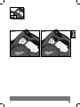
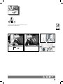
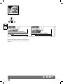
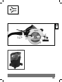
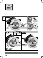
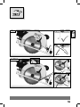
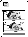
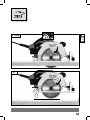
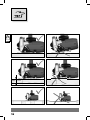
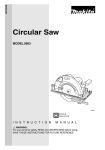
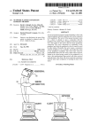
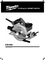
CS 60
Original instructions
Important!
It is essential that you read the instructions in this manual before
operating this machine.
Subject to technical modifications.
I
II
III
IV
V
VI
Aufnahme
aufschrauben
x cm
x cm
VII
VIII
Accessory
TIP
1.
I
1
2.
3.
2
4
2
lock
3
1.4.
1
I
2
5.
3
lock
4
3
2x
I
4
1.
Start
2.
Stop
II
5
0 – 45°
0 – 56°
56°
0 – 45°
56°
0 – 56°
56°
3
2
2
1
49 mm
61 mm
35 mm
0° ................. 45°....................... 56°
6
56°
III
To correct the 90° angle of the guide-plate to the saw
blade, use the correction screw.
III
1
90°
3
2
7
x cm
x cm
1.
1
IV
2
2.
3.
Carry out a test cut
0°
x cm
x cm
8
45°
V
1
2
3
0 – 61 mm
9
V
Adjust the cutting depth to the thickness of the workpiece. Less
than a full tooth of the blade teeth should be visible below the
workpiece.
10
Aufnahme
aufschrauben
VI
AS300ELCP
11
Aufnahme
aufschrauben
TIP
1. Start
VII
2.
3. Stop
0°
12
45°
Aufnahme
aufschrauben
TIP
1.
1
VII
0°
> 0°
2. Start
13
TIP
Aufnahme
aufschrauben
3.
VII
VII
4.
14
Aufnahme
aufschrauben
TIP
5. Stop
VII
VII
6.
15
TIP
Aufnahme
aufschrauben
VII
VII
max. 61 mm
16
VII
technIcal Data
circular saw
CS 60
110 - 120 V
220 - 240 V
Rated input .......................................................................................................................................1600 W............................................ 1600 W
No-load speed ..................................................................................................................................5800 min-1.......................................5800 min-1
Saw blade dia. x hole dia ......................................................................................................... 184x15.88 mm.................................184x15.88 mm
Cutting depth max. at 90°/45°/56° ........................................................................................... 61/49/35 mm...................................61/49/35 mm
Weight according EPTA-Procedure 01/2003....................................................................................4,8 kg .............................................. 4,8 kg
Noise/vibration information
Measured values determined according to EN 60 745.
Typically, the A-weighted noise levels of the tool are:
Sound pressure level (K = 3 dB(A)) ...................................................................................................92,0 dB(A) ....................................... 92,5 dB(A)
Sound power level (K = 3 dB(A)) .....................................................................................................103,0 dB(A) ..................................... 103,5 dB(A)
Wear ear protectors!
Total vibration values (vector sum in the three axes) determined according to EN 60745.
Vibration emission value ah .................................................................................................................2,9 m/s2........................................... 2,3 m/s2
Uncertainty K .......................................................................................................................................1,5 m/s2 .......................................... 1,5 m/s2
WARNING
The vibration emission level given in this information sheet has been measured in accordance with a standardised test given in EN 60745 and
may be used to compare one tool with another. It may be used for a preliminary assessment of exposure. The declared vibration emission level
represents the main applications of the tool. However if the tool is used for different applications, with different accessories or poorly maintained,
the vibration emission may differ. This may significantly increase the exposure level over the total working period.
An estimation of the level of exposure to vibration should also take into account the times when the tool is switched off or when it is running but
not actually doing the job. This may significantly reduce the exposure level over the total working period. Identify additional safety measures
to protect the operator from the effects of vibration such as: maintain the tool and the accessories, keep the hands warm, organisation of work
patterns.
WARNING! Readallsafetywarningsandallinstructions,
includingthosegivenintheaccompanyingbrochure. Failure
to follow the warnings and instructions may result in electric shock,
fire and/or serious injury. Saveallwarningsandinstructionsfor
futurereference.
hardware of the saw will run eccentrically, causing loss of control.
Never use damaged or incorrect blade washers or bolt. The
blade washers and bolt were specially designed for your saw, for
optimum performance and safety of operation.
Causes and operator prevention of kickback:
kickback is a sudden reaction to a pinched, bound or misaligned saw
Safety InStructIonS
blade, causing an uncontrolled saw to lift up and out of the workpiece
Cutting procedures
toward the operator;
- when the blade is pinched or bound tightly by the kerf closing down,
DANGER: Keep hands away from cutting area and the
the blade stalls and the motor reaction drives the unit rapidly back
blade. Keep your second hand on auxiliary handle, or motor housing.
toward the operator;
If both hands are holding the saw, they cannot be cut by the blade.
Do not reach underneath the workpiece. The guard cannot protect - if the blade becomes twisted or misaligned in the cut, the teeth at the
back edge of the blade can dig into the top surface of the wood causing
you from the blade below the workpiece.
the blade to climb out of the kerf and jump back toward the operator.
Adjust the cutting depth to the thickness of the workpiece.
Kickback is the result of saw misuse and/or incorrect operating
Less than a full tooth of the blade teeth should be visible below the
procedures or conditions and can be avoided by taking proper
workpiece.
precautions as given below.
Never hold piece being cut in your hands or across your leg.
Maintain a firm grip with both hands on the saw and position
Secure the workpiece to a stable platform. It is important to
your arms to resist kickback forces. Position your body to either
support the work properly to minimize body exposure, blade binding,
side of the blade, but not in line with the blade. Kickback could cause
or loss of control.
the saw to jump backwards, but kickback forces can be controlled by
Hold power tool by insulated gripping surfaces when
the operator, if proper precautions are taken.
performing an operation where the cutting tool may contact
When blade is binding, or when interrupting a cut for any
hidden wiring or its own cord. Contact with a “live” wire will also
reason, release the trigger and hold the saw motionless in the
make exposed metal parts of the power tool “live” and shock the
material until the blade comes to a complete stop. Never attempt
operator.
When ripping always use a rip fence or straight edge guide. This to remove the saw from the work or pull the saw backward while
improves the accuracy of cut and reduces the chance of blade binding. the blade is in motion or kickback may occur. Investigate and take
corrective actions to eliminate the cause of blade binding.
Always use blades with correct size and shape (diamond versus
When restarting a saw in the workpiece, centre the saw blade
round) of arbour holes. Blades that do not match the mounting
17
GB
in the kerf and check that saw teeth are not engaged into the
material. If saw blade is binding, it may walk up or kickback from the
workpiece as the saw is restarted.
Support large panels to minimise the risk of blade pinching and
kickback. Large panels tend to sag under their own weight. Supports
must be placed under the panel on both sides, near the line of cut and
near the edge of the panel.
Do not use dull or damaged blades. Unsharpened or improperly set
blades produce narrow kerf causing excessive friction, blade binding
and kickback.
Blade depth and bevel adjusting locking levers must be tight
and secure before making cut. If blade adjustment shifts while
cutting, it may cause binding and kickback.
Use extra caution when making a „plunge cut“ into existing
walls or other blind areas. The protruding blade may cut objects
that can cause kickback.
Function of the bottom guard
Lower guard function
Check lower guard for proper closing before each use. Do not
operate the saw if lower guard does not move freely and close
instantly. Never clamp or tie the lower guard into the open
position. If saw is accidentally dropped, lower guard may be bent.
Raise the lower guard with the retracting handle and make sure it
moves freely and does not touch the blade or any other part, in all
angles and depths of cut.
Check the operation of the lower guard spring. If the guard and
the spring are not operating properly, they must be serviced
before use. Lower guard may operate sluggishly due to damaged
parts, gummy deposits, or a build-up of debris.
Lower guard should be retracted manually only for special cuts
such as „plunge cuts“ and „compound cuts.“ Raise lower guard
by retracting handle and as soon as blade enters the material,
the lower guard must be released. For all other sawing, the lower
guard should operate automatically.
Always observe that the lower guard is covering the blade
before placing saw down on bench or floor. An unprotected,
coasting blade will cause the saw to walk backwards, cutting whatever
is in its path. Be aware of the time it takes for the blade to stop after
switch is released.
Please do not use abrasion disks in this machine!
Wear ear protectors. Exposure to noise can cause hearing loss.
The dust produced when using this tool may be harmful to health. Do
not inhale the dust. Use a dust absorption system and wear a suitable
dust protection mask. Remove deposited dust thoroughly, e.g. with a
vacuum cleaner.
Appliances used at many different locations including open air should
be connected via a residual current device (FI, RCD, PRCD) of 30mA or less .
Always disconnect the plug from the socket before carrying out any
work on the machine.
Only plug-in when machine is switched off.
Do not use inserted tools not corresponding to the key data given in
these instructions for use.
Keep mains lead clear from working range of the machine. Always lead
the cable away behind you.
Before use check machine, cable, and plug for any damages or material
fatigue. Repairs should only be carried out by authorised Service
Agents.
Do not fix the on/off switch in the “on” position when using the saw
hand-held.
18
SpecIfIeD conDItIonS of uSe
This circular saw can cut lengthways and mitre accurately in wood,
plastic, and aluminium.
ec-DeclaratIon of conformIty
We declare under our sole responsibility that this product is in
conformity with the following standards or standardized documents.
EN 60745, EN 55014-1, EN 55014-2,
EN 61000-3-2, EN 61000-3-3, in accordance with the regulations
2006/42/EC, 2004/108/EC
Winnenden, 2011-01-14
Rainer Kumpf
Manager Product Development
Authorized to compile the technical file.
maInS connectIon
Connect only to single-phase a.c. current and only to the system
voltage indicated on the rating plate. It is also possible to connect to
sockets without an earthing contact as the design conforms to safety
class II.
maIntenance
Clean only with dry cloth. Certain cleaning agents and solvents are
harmful to plastics and other insulated parts. Keep the apparatus
handle clean, dry and free of oil or grease.
The ventilation slots of the machine must be kept clear at all times.
It is recommended to regularly use cleaner for the clamping jaws and
the clamping jaw borings.
Use only Milwaukee accessories and spare parts. Should components
need to be exchanged which have not been described, please contact
one of our Milwaukee service agents (see our list of guarantee/service
addresses).
If needed, an exploded view of the tool can be ordered. Please state
the ten-digit No. as well as the machine type printed on the label and
order the drawing at your local service agents or directly at: Milwaukee
Elektrowerkzeuge, Max-Eyth-Straße 10, D-71364 Winnenden, Germany.
SymbolS
Please read the instructions carefully before starting the
machine.
Always disconnect the plug from the socket before
carrying out any work on the machine.
Accessory - Not included in standard equipment,
available as an accessory.
Do not dispose of electric tools together with household
waste material! In observance of European Directive
2002/96/EC on waste electrical and electronic
equipment and its implementation in accordance with
national law, electric tools that have reached the
end of their life must be collected separately and
returned to an environmentally compatible recycling
facility.
Copyright 2011
Milwaukee Electric Tool
Max-Eyth-Straße 10
D-71364 Winnenden
Germany
+49 (0) 7195-12-0
(01.11)
Printed in Chain
4931 4252 03
961067643-01(A)