1
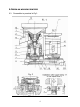
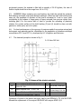
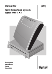
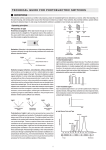
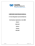
PUGACHEV
Centrifugal Inertial Concentrator
for extraction of prestigious metals
PCC-2
User
Manual
TABLE OF CONTENTS
1. Purpose of product ......................................................... 2
2. Packing list ……………………………………………………………….… 2
3. Specifications …………………………………………………..……….… 3
4. Design and working principle ........................................... 4
5. Safety directions ............................................................. 7
6. Preparation and organization of products for work ….......... 7
7. Maintenance ................................................................... 8
8. Possible faults and ways to overcome them ...................... 10
9. Manufacturer Warranty …………………………………………..….… 11
10. Transportation and storage ............................................ 11
11. Information on claims …………………………………………….…... 11
1
1. Purpose of product
1.1.
Pugachev Centrifugal concentrator is designed for high-gravity concentration of
small samples of fine material (sand placers or finely crushed ore) containing free
gold, silver and platinum, in the conduct of exploration work in order to identify
and assess the industrial fields, containing precious metals.
1.2.
Concentrator can be used:
- In the laboratory practice of geological exploration work in the mineralogical and
technological research of mineral raw materials containing precious metals;
- For processing sluice concentrates on concentrating factories, finishing points,
artisanal team;
- When testing technologies for the extraction of gold and platinum from ores,
placers and non-traditional raw materials (electronic scrap, waste and
metallurgical affinage production);
- When evaluating the quality of work on ore concentrating mills and artisanal
crews through comprehensive mineralogical and technological research of
products of mineral processing;
- With off-balance-sheet developing of low scale plots, subsurface technogenic
dumps, remote areas and bad tapped territories by individual entrepreneurs and
prospectors.
1.3.
Exploitation of the concentrator to produce in a room or under a canopy with a
positive temperature.
1.4.
The design of the concentrator implemented the following patents:
- Patent number 2079370 «Method of vibration-centrifugal separation of
mixtures»;
- Patent number 2109570 «Centrifugal concentrator for loose materials».
- Patent number 2129047 «Centrifugal concentrator».
2. PACKING LIST
Pugachev Centrifugal concentrator, vibrating TSKP-0, 2 - 1 pc.
Passport - 1
Set of spare parts – 1
The set of tools and accessories - 1
Packaging: packing box – 1
2
3. SPECIFICATIONS.
2.1.
Size of material, mm - less than 2.
2.2.
Performance of solids, kg/hour:
maximum (for sand placers) 200; optimum (for grinding ores) 50 - 75.
2.3.
Dilution pulp (ratio of solid to liquid), kg/kg
S:L of 1:4-1:6 (for placers) and 1:8-1:12 (for the ore).
2.4.
The volume of concentrate produced, milliliters: 40...80.
2.5.
Extraction of gold and platinum in concentrate, %:
class size -500+40 microns - to 98%;
class size -10 microns - to 68%.
2.6.
The installed capacity of not more than 0.27 kW.
2.7.
Characteristics of voltage: three-phase voltage, V 220/380
single-phase, V 220
frequency, 50 Hz
2.8.
Overall dimensions: length 455 mm; width 290 mm; height 400 mm.
2.9.
Weight: 28.5 kg.
2.10. The average time between failures: not less than 500 hours.
2.11. The average full term of service: 5 years.
2.12. Average recovery of the state of not more than 5 hours.
2.13. The resistance between the grounding bolt and every available for touching metal
(not conductor part) of the product should be not more than 0.1 ohms.
2.14. Insulation resistance of circuit power must be at least 20 Mega ohms.
*) Drive maximum performance with the ideal operating conditions (achieved when
tested on artificial mixtures of quartz sand and granulated ferrosilicon) allowing for high
extraction of small and thin heavy particles. The equipment may not achieve the best
performance with maximum performance, depending on the material composition of
material of particles of heavy minerals and nutritional characteristics.
3
4. DESIGN AND WORKING PRINCIPLES
4.1.
Concentrator is presented in Fig. 1.
4
Concentrator consists of a working enriching device - conical bowl (1) with
removable rubber liner (2) with a catch on the inner surface of annular grooves for
accumulating concentrate. Bowl (1) through carving mounted on a friction shaft (3), free
(with a gap 2-2,5 mm) installed in the concentrator 4 through a flexible shaft (clutch) (5)
on the shaft (6) of bearing concentrator (7). The bearing concentrator located on the
base (8). The base also supports the drive (9) which reducing the wedge belt drive (10),
one of the pulleys (11) (he planted on the lower end of the shaft (6)) which is the
flywheel, and the collector-casing (12) with an output pipe (13) to output the tails of
enrichment, and with removable hopper (14). To reduce noise and vibration during the
work of concentrator, sleeve (3) is embodied in the massive disk (15) defined by using
tubular shock absorbers (16) on the base (8). The drive (9) is electrically connected to
the control panel (in Fig. 1 is not shown.)
4.2. The operating principle of the concentrator is in the separation by density of
granular material moving in the cup (1) in the form of pulp. Separation occurs as a result
of intense vibration fluctuations of bowl which commits planetary rotary motion as a
result of friction torsion of shaft (3) on the inner surface of sleeve (4). Emerging with a
circular high-frequency circular vibration of the bowl with a small (2...2.5 mm) amplitude
of oscillations provide during the work of concentrator a significant sign variables load on
the pulp, contributing effectively to loosening mineral «bed» in annular grooves of rubber
liner (2), and better segregation (penetration inside) small heavy minerals through the
gaps between large light grains. As a result, the heavy minerals are accumulated inside
the grooves of the wall liner to form a concentrate and displacing light minerals forming
the tails of enrichment, which makes the bottom-up flow of the pulp upward and through
the edge of the bowl (1) are discharged into accumulator (12).
Next, by the sloping bottom of an accumulator through the tail pipe (13), the tails
are flowing out of the concentrator to the tail receiver. With high productivity and a
significant enrichment of the content with heavy minerals, it is recommended the
repeated (control) enrichment of tails (especially in the search and evaluation work.)
After each stage of enrichment, the concentrator should be stopped, the hopper (14)
need to be taking off, and the rubber bushing (2) with accumulated concentrate from the
bowl (1) need to be removed. Due to the elasticity of the walls, evert the bushing (2)
(like stockings), and wash away the concentrate with water thoroughly from the grooves
in the bowl. Sent the concentrate to the fine-tuning, and prepare the concentrator for the
further work. Jet the inner walls of the enclosure with water through the shower device
(it is included in the set of tools and accessories), carefully wash the residual tailings
from the inner walls of the enclosure-compendium (12), install clean rubber liner (2) in
the cup (1) cup, and the unit is ready to work again.
4.3. In conducting laboratory research on enriching the gold samples, it is
recommended in each experiment at least two or three stages of enrichment. After each
stage of enrichment, remove the concentrates separately to examine the nature of
recoverable gold and related minerals identified in the concentrates.
4.4. When working with materials that contain more than 10% heavy minerals, the
concentrator is configured to work in soft mode (ie, set a lower intensity of the
5
enrichment process: the material is filed with a capacity of 30-50 kg/hour, the ratio of
Solid to Liquid should be in the range from 1:8 to 1:12).
4.5. WARNING! When replacing worn-out bushing, the shaft also should be replaced.
Both bushing and shaft must have identical markings. (When the shaft and bushing bowl
wear out, the amplitude of vibration of the bowl is increased to 3 mm or more, what
contributing to the release of large grains of heavy minerals from grooves rubber liner,
including gold.) For the secure start of bowl to provide the operating of planetary
rotation, the contact surface of the shaft bushing (3) and (4) should be clean out with
gasoline or white spirit, and roll in place.
4.6. For best performance on the recovery of precious metals from various mineral and
technogenic raw materials use the «Guidelines on the application of vibration-centrifugal
concentrators PCC-1 and PCC-2», developed by LLC «Pugachev and Partners».
4.7.
The electrical principle is shown in Fig. 2.
3~ 50 Herz 380 Volt
Fig. 2 Scheme of the electric principle
Marked
Q-ty
Note
M1
Engine AIR71V6U3 TU 16-525.564-84
Tested IM 3081
Description
1
N=0,55 kW, n=915 rpm
K1
Starter magnetic PML - 12 300 - 2B
1
U=380 V, 50 Hz;
I (heat energy)=2,4...4A
X1
X2
Socket RSH 30-0-V-25/380 GOST 7396-76
Plug VSH-V-A-25/380 GOST 7396-76
1
1
Connection of power to the starter and motor lead by wire RPSh4h1,0 TU 16-K18.001-89.
Allowed the replacement of the engine AIR63A4UZ with engine AOLM-21/4.
6
5. INSTRUCTIONS OF SAFETY MEASURES
5.1. The person allowed to service concentrator must be familiar with it and must
follow the safety instruction.
5.2. Before starting the work, the concentrator needed to be grounded with the wire.
5.3. When conducting maintenance, concentrator must be disconnected from the
electrical network and precautions need to be taken against erroneous activation of the
electrical connection.
5.4. You may not:
1) turn on a concentrator without connecting to the ground;
2) prevent the overflow of pulp from the hopper to avoid getting the water on the
electric pulp;
3) operate a concentrator at the wrong direction of rotation of the bowl.
6. PREPARATION FOR WORK AND ORGANIZATION OF WORK.
6.1. Operation of the concentrator must be implemented in the production room
(laboratory), equipped with water-supply system (technical water, pressure P= ...2 atm),
electricity (three phase voltage 220/380 V frequency 50 Hz. [or 110 V/60Hz with
transformer], power 0.5 kW) and the ground contour.
Permissible to operate a concentrator in the field (exploration, mining of the small
precious metal by prospectors) under a canopy on a flat area with a hard surface with a
positive temperature.
6.2. Before the start of operation, unpack a concentrator, remove the hopper and
block the shaft with the pin-plug stopper (it is enclosed in a set of accessories and tools),
turn off the cup and release it from the cardboard liner, which preventing the cup from
the impact with neck jacket-collector during shipment from the manufacturer to the
customer.
Then turn on shaft back on the cup and remove the pin-plug stopper.
Ground the concentrator.
Connect the electricity.
Turn on the motor drive of the cup and, looking at it from above, check the
correctness of the direction of its rotation. The cup should rotate in counter-clockwise
direction, and match the direction of the arrows on the collector.
Connect the spray device to a water line, and install a hopper to the concentrator.
6.3.
The order of work with the concentrator:
- Placed under the outlet of nozzle casing some vessel with capacity of not less
than 3 gallons for receiving tails. When you repeat recoveries, provide larger capacity in
a tank of 12-15 gallons with overflow pipe with the possibility of installing inside a 3…4gallon bucket.
- Put the pre-prepared for the class of -2 mm material in the bowl in the capacity
7
of 2-3 gallons, shake with water (avoid overflow), set the bowl to a height exceeding the
top of the concentrator’s hopper.
- Turn the electric motor of concentrator, making sure that the bowl is ready for
the enrichment operation by special vibrating sound, and begin to develop the material.
- Take by the left hand shower device and pointing it to the hopper, open the
valve to flush the hopper with the water to the value at which the water will fill the crater
of hopper at 1/4-1/5 of its conical surface.
- Take by right hand a scoop and by portions of not more than 150-200 gram of
cast material in hopper, carefully blurring it, and avoiding falling into the feeding tube
grain size of more than 7 mm to prevent clogging the latter.
- Add the optimum density of the pulp (see section 2.3) and guided by the
provisions of paragraph 4.2., 4.3. and 4.4. handle all of the mass of material, then within
10...15 seconds serve clean water, removing individual grains from the crater, and turn
off water valve.
- Switch off the electric engine and, without waiting for a complete stop of the
bowl, remove the hopper.
- After stopping the bowl carefully remove the rubber liner with accumulated
concentrate and evert it inside out and carefully wash off concentrate in a bowl until the
complete removal of all grains.
Enrichment cycle is complete. With doing control (second) enrichment of tailings,
material need to be removed from the receiving tank, re-loaded into the bowl, and the
process repeated in the sequence described above.
7. MAINTENANCE
7.1. Maintenance of Concentrator provided by fitter and electrician.
7.2. Once a week should be preventive inspection:
1) before the examination to remove switch in collector-casing (12) (in Fig. 1 is
not shown);
2) visually check the status of the flexible shaft (5) which transmits torque from
the engine (9) to the cup (1); when it detects damage of the shaft, replace it;
3) check the reliability of fastening of the flexible shaft (5) on the hub shaft (6) of
bearing (7) and the hub shaft (3), carrying the cup (1), if easing of mounting detects,
screw tighten the clamps (17 and 18);
8
4) for the replacement of the flexible shaft (5) should turn off the cup (1) of the
shaft (3), for which through an opening in the collector (12) you must insert the pinstopper (it is included in the kit of tools and accessories) until it locks in the hole in the
shaft;
5) remove the collector (12) from the base (8) after screw out from the base the
screws fastening the casing;
6) enclasping a disc (15) with both hands, lift it from the rubber tube shock
absorbers (16), thereby providing free access to the shaft (3);
7) reducing the fastening screws of clamps (17 and 18), remove frayed flexible
shaft (5) from the shafts (3 and 6) and replace it with a new from the enclosed kit of
spare parts;
8) after installing a new flexible shaft (5) securely tighten the fastening screws of
clamps (17 and 18), and put disk (15) on the tube shock absorbers (16);
9) after the installation of disc (15) use the mechanic’s ruler to verify parallelism of
bottom plane compare to the support plane of the bearing hub flange (7), allowance for
not parallel must not exceed 1 mm. Adjusting the parallelism produce with the help of
nuts 19 (see Fig. 1), while providing output of shaft (3) over the bushing (4) in the
2.5...3 mm;
10) when replacing worn shaft (3) and sleeve (4) of vibration gear to new (from a
spare part kit), wriggle them out of the disc (15) of mounting screw pin, and through the
consistent screwing these screws into the screw holes on the flange sleeves all the way
to the top plane of the disk, press out the worn sleeve from the cone hole of the disc;
11) insert a conical end of a new bush into a conical hole of the disc (15) and fix it
with screws to avoid cranking;
12) now install and mount the collector to the base and screw on to the working
shaft of the bowl. The preventive inspection of concentrator before the operation is
complete.
7.3. Before each work shift, the preventive inspection of electrical part should be done:
1) visually check the cable connecting the motor with the starter;
2) check the reliability of the ground wiring; if weakening of the tightening
grounding screw get noticed, tighten it.
7.4. Once a quarter, it is necessary to check the tension of V-belt (10), and its condition.
Stretch the belt with bolt (20).
7.5. Once a year, replace lubrication of bearings in the bearing node (7).
9
8. POSSIBLE FAULTS AND WAYS TO OVERCOME THEM
8.1. Possible malfunctions and ways to overcome them are presented in the following
table.
Description
of failure
The likely failure cause
Method to remove the problem
1. Motor not
started.
Contacts disconnected, cable
breakage.
Tighten the screws in the field of
contacts, restore the wire breakage.
2. Bowl (1)
not working.
Weakening of threaded
connection of bowl with the
shaft.
Tighten threaded connections.
Weakening the connection of a
flexible shaft with friction shaft,
or with the shaft of bearing
unit.
Tighten the screws of mounting
clamps of the flexible shaft.
The gap in flexible shaft.
Replace the flexible shaft with new.
Water has been in gap between
the shaft.
Remove (turn) working bowl from
the cut shaft. Turn on electric motor
drive, and by inserting in the gap
between the rotating shaft and
bushing factional strips of paper
width 15...20 mm to a depth of
20...25 mm, and rotate it in the
opposite direction to remove (drip)
the moisture. Then, not switching
the drive off, insert in a space the
similar strip of medium grain skin
sanding paper, and with a light blow
to the end of the rotating shaft with
a wood object (such as a
screwdriver handle), put the shaft in
friction planetary motion for 5...10
minutes.
Weakening of plug attachment
(21) in plate (26).
Tighten the bolts (9) of the two
halves of plate (26).
Not adapted (not having
identical markings) the working
surfaces of friction shaft and
bushing.
Perform
adapting
of
working
surfaces of the friction shaft and
bushing (see section 4.5.)
10
9. MANUFACTURER WARRANTY
12.1. Subject to the conditions of transportation, storage and operation of the
concentrator according to the requirements of this passport, business manufacturer
guarantees the non-failure of its work within 6 months from the date of entry into
service.
12.2. Warranty period of storage is 6 months.
12.3. During the warranty period of operation, the manufacturer guarantee to supply
free parts to change the defective parts of concentrator.
12.3. The average total lifetime is 5 years.
10. TRANSPORTATION AND STORAGE
13.1. Concentrator need to be covered during the transportation.
13.2. Conditions of concentrator’s storage and transportation in the impact of climatic
factors meet the group ZH2 GOST 15150-69 (at an outside temperature of -50° F to
+104° F, and relative humidity 80% at 20
11. INFORMATION ON CLAIMS
14.1. In the event of failure of the concentrator during the guarantee period of
exploitation, as well as the discovery of incomplete parts, the consumer must send
written notice to the manufacturer with the following data:
1) the name of the product;
2) serial number;
3) the date of entry into service;
4) the date of issue;
5) the nature of failure or incomplete;
6) the address and telephone number of the consumer.
14.2. In the event of failure of the product after the end of the warranty period, please
send us feedback on the product to the address of the manufacturer:
Russia, 249030, Kaluga Region, Obninsk, prospect Marksa, 46.
Россия 249030, Калужская обл., г. Обнинск, пр-т Маркса, 46.
Phone / Fax 8 (48439) 4-94-91
E-mail: [email protected]
THANK YOU FOR PURCHASING PUGACHEV CONCENTRATOR PCC-2!
11
YOUR DEALER IN THE U.S.A. and RUSSIA
SURVEYORS EXCHANGE COMPANY, INC.
3323 DeArmoun Road
Anchorage, AK 99516
907.345.6500
907.345.7836 fax
Contact: Larry Wilmarth
[email protected]
www.gold-rus.com
www.tse-ak.com
In Gold We Trust!
Published August 2009, Anchorage, Alaska. All Rights Reserved.
Translation from Russian, Design © Surveyors Exchange Co., Inc.
12