1
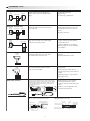
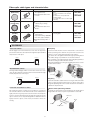
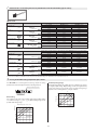
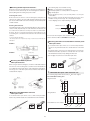
T EC H N I CAL GU ID E F O R P H OTOELECTRIC SW ITCHES
DEFINITIONS
Photoelectric switches operate by an emitter unit producing a beam of modulated light that is detected by a receiver, either free-standing or in
the same housing, and sensing action occurs when the beam is broken by an object. These switches, like proximity switches, operate without
touching the detected object. A wide range of photoelectric switches is available to meet virtually any application need.
Operating principles
Properties of light
LED
Rectilinear propagation: When light travels through air or water, it
always travels in a straight line. The aperture mask on the outside of a
thru-scan switch that is used to detect small objects is an example of
how this principle is applied to practical use.
Non-polarized
light
Polarizing
filter
Polarized
light
(Cannot pass light)
Vertically
polarized light
Light
Horizontally
polarizing filter
(Passes light)
Refraction: Refraction is the phenomenon of light being deflected as
it passes obliquely through the boundary between two media with
different refractive indices.
Light sources, emission methods
(Air) Refractive index 1
< Pulse Modulated light >
(Glass) Refractive index 1.5
(Air) Refractive index 1
Light
Light is emitted repeatedly at fixed intervals. The effects of ambient
light interference are easily removed with this system, enabling long
distance detection. In models equipped with anti-mutual interference
function, the emission cycle is varied within a specified range to
handle coherent light and ambient light interference. The majority of
photoelectric switches use pulse modulated light.
Cycle
0
Time
< Non-modulated Light >
Non-modulated light refers to an uninterrupted beam of light at a
specific intensity. Although these switches have fast response times,
their drawbacks include short sensing distances and susceptibility to
ambient light interference.
Light intensity
Reflection (regular reflection, retroreflection, diffuse reflection):
A flat surface, such as glass or a mirror, reflects light at an angle
equal to the incident angle of the light. This kind of reflection is called
regular reflection. A corner cube takes advantage of this principle by
arranging three flat surfaces perpendicular to each other. Light
emitted toward a corner cube repeatedly propagates regular
reflections and the reflected light ultimately moves straight back
toward the emitted light. This is referred to as retroreflection. Most
reflectors are comprised of corner cubes that measure several square
millimeters and are arranged in a precise configuration. Matte
surfaces, such as white paper, reflect light in all directions. This
scattering of light is called diffuse reflection. This principle is the
detection method used by diffuse-scan switches.
Light
Vertically
polarizing filter
Light intensity
Light
Vertically
polarized light
Light
0
Regular Reflection
(Mirror)
Retroreflection
(Corner cube)
Time
Diffuse Reflection
(Paper)
Light Source Color and Type
1
Red laser
Infrared LED
Light intensity
Polarization of Light: Light can be represented as a wave that
oscillates horizontally and vertically. Photoelectric switches almost
always use LEDs as the light source. The light emitted from LEDs
oscillates in the vertical and horizontal directions and is referred to as
non-polarized light. There are optical filters that constrain the
oscillations of non-polarized light to just one direction. These are
known as polarizing filters. Light from an LED that passes through a
polarizing filter oscillates in only one direction and is referred to as
linear polarized light. Polarized light oscillating in the vertical direction
cannot pass through a polarizing filter that constrains oscillations to a
perpendicular direction (e.g., the horizontal direction). The polarized
retroreflective switches and the anti-mutual interference filter
accessory for thru-scan switches operate on this principle.
Red LED
Blue LED
Green
LED
100
200
300
Ultraviolet
X-rays
400
500
600
700
Visible
800
900
1,000
1,100 Wavelength (nm)
Infrared
Microwaves
SCANNING TYPE
Type
Principle
Thru scan
Emitter
Target object
Receiver
Retroreflective
Polarized retroreflective
Emitter/
receiver
Target object
Reflector
Diffuse scan
Emitter/
receiver
Target object
Limited diffuse-scan
Emitter/
receiver
Major features
Switch operates when the light between
emitter and receiver is blocked by a target
object.
Long-distance detection.
High accuracy.
A wide range of applications.
Operation is the same as for a thru-scan
switch, but emitter and receiver are housed
in the same unit.
The optical axis can be set easily.
Wiring and installation work are easy
and wiring is necessary for only one
device.
Requires areflection.
Light from the emitter is reflected by the
target object itself. When the reflected light
is detected, the switch operates.
Wiring and installation work are needed
only for switch itself, and installation
requires little space.
Light axis alignment is not required.
Models capable of color discrimination
are available.
Emitter and receiver operate only at a
certain angle. Detection occurs only where
the emitter and receiver axes meet.
Influence of background can be
reduced.
Operation differential is small.
A beam of light strikes the target object,
which is detected by the difference in the
angle of the reflected light.
No interference from high reflectance
backgrounds.
Even if reflectance differs by color or
material, target object can be detected
reliably.
Small target objects can be detected
with high accuracy.
Fiber-optic cable is comprised of a central core with a high refractive
index surrounded by cladding with a low refractive index. Repetitive
total internal reflection at the boundary of the less refractive cladding
guides the light down the fiber-optic cable. The angle of the light
traveling through the fiber-optic cable increases to about 60 by the
time the light exits the fiber.
Highly resistant to noise and other
environmental influences with no
electrical components in the fiber-optic
cable.
Flexible to various applications with
variety of fiber unit line up.
Target object
Background suppression
Emitter/
receiver
Target object
Fiber-optic switches
Refractive index
Cladding Core
sheath
Cladding
Core
Approx.
60˚
LED
Fiber-optic cable
Fiber-optic cable
Light
Target object
Fiber unit
60˚
Emitter
Light
Receiver
Amplifier
Typical consoles of fiber-optic switches
HPX series potentiometer tuning fiber-optic switches
Sensitivity adjustor (3 turns)
Light indicator (red)
Stability indicator (green)
HPX-AG/EG digital fiber-optic switches
SP (green)
L-ON/D-ON selector
AUTO/OK: Auto tuning button
OFF-Delay switch
Output indicator (orange)
Indicator
2
PV (red)
FUNC/CANCEL:
Function selector
+ button
– button
Fiber-optic cable types and characteristics
Cross section
Structure
Unbreakable
(Multi-core)
Features
Effective applications
Compared to conventional regular
fibers:
As easy to install as soft electrical
wiring.
Never have to worry about the
bending radius.
Touching fibers does not affect light
intensity.
Thru scan:
Efficient light transmission at
relatively long scanning
ranges.
Allowable bend radius: 10 or
20 mm.
General use, low cost.
Thru scan:
Excellent bending-resistance
characteristics.
Repeated bending: 1,000,000
times min. (typical example)
Allowable bending radius: 4
mm.
Resists damage when mounted
to moving parts
(Integrated cores)
Regular
(single core)
Bend-tolerant
(bundle)
(separate cores)
Typical models
Bending does not almost
affect light intensity.
Allowable bend radius:1 mm
or 2 mm.
HPF-T025
Diffuse scan:
HPF-D030
HPF-T003
Diffuse scan:
HPF-D002
Thru scan:
HPF-T008
Diffuse scan:
HPF-D037
GLOSSARY
Thru-scan switch
[Principles]
A beam (light) receiver and emitter face each other. An object that
passes between them is detected when the light intensity transmitted
drops because of the object.
Emitter
Receiver
This function and structure uses the characteristics of the reflector
and the polarizing filters built into the polarized-retroreflective
switches to receive only the light reflected from the reflector.
The waveform of the light transmitted through a polarizing filter in
the emitter changes to polarization in a horizontal orientation.
The orientation of the light reflected from the triangular pyramids of
the reflector changes from horizontal to vertical.
This reflected light passes through a polarizing filter in the receiver
to arrive at the receiver.
Longitudinal wave
Vertically
polarizing filter
Reflector
Retroreflective switch
Receiver
An integrated beam (light) emitter-receiver and a reflector face each
other. An object that passes between them is detected when the light
intensity drops because of the object.
Emitter/receiver
Reflector
Emitter
Transvers
wave
Corner cube
Horizontally
polarizing
filter
[Purpose]
This method enables stable detection of targets with a mirrorlike
surface. Light reflected from these types of objects cannot pass
through the polarizing filter on the receiver because the orientation of
polarization is kept horizontal.
Polarized retroreflective switch
Beam strikes polarizing reflector
This relatively new type of switch solves a problem of conventional
retroreflective switches. Conventional models cannot reliably detect
highly reflective target objects because the beam reflected by the
reflector cannot be distinguished from light reflected by the target
object. However, the use of polarized light allows reliable detection of
highly reflective objects, and is nearly as reliable as thru scan
sensing.
The beam is polarized in the horizontal plane by the emitter. When
the light strikes the reflector, its plane of polarization is rotated 90˚.
Emitter beam
HP100
Reflector
Reflected beam
3
Beam strikes a normal reflective surface
Background suppression switches
The target object reflects light waves without changing their plane of
polarization. These reflected waves are eliminated by a filter.
Reflective object
Detection method
The receiver in the switch is a dual photodiode. Target objects closer
to the present position are detected by means of beam concentrated
position on the photodiode.
Receptors (dual photodiode)
Emitter beam
N
Variable F
set
distance
Emitter
LED
HP100
Reflector
The lens is set to
upper limit for the
FHDK10.
N: Near
F: Far
Set distance
Reflected beam
Detectable area
Undetectable area
[Features of background suppression switches]
When a polarized retroreflective switch is used to detect highly
reflective object or objects that disturb polarization, detection might be
inconsistent. In such case, take the following countermeasures:
Examples of target object that might cause faulty operation:
Target object covered with a transparent film
Semi-transparent target object (semi-transparent case, etc.)
Mirror or highly reflective mirrorlike object
Countermeasures:
Mount the switch at a slight angle to the target object.
Increase the distance between the switch and the target object.
Lower the sensitivity setting of the switch.
Operation not greatly affected by target object surface conditions or
color.
Operation not greatly affected by the background.
Beam emitter
This includes a light source, such as a light-emitting diode (LED),
and an optical system (lens).
Beam receiver
The receiver uses a photoelectric conversion device, such as a
photo transistor, to detect the beam from the emitter through an
optical system (lens).
Diffuse-scan switch
A beam emitter and a beam receiver are located in close proximity. A
passing or approaching object is sensed by the change in the quantity
of reflected light caused by the object.
Emitter/receiver
Scanning range
This is the range within which the photoelectric switch operates
reliably.
Thru-scan switch
Target object
The maximum distance between emitter and receiver at which
operation is reliable.
Emitter
Receiver
Limited diffuse-scan switches
Scanning range
Limited diffuse-scan switches
Detection method
Retroreflective switch
In the same way as for diffuse-scan switches, limited diffuse-scan
switches receive light reflected from the target object to detect it. The
emitter and receiver are installed to receive only regular-reflection
light, so only objects that are a specific distance (area where light
emission and reception overlap) from the switch can be detected. In
the figure on the right, the target object at (A) can be detected while
the object at (B) cannot.
Receiver
element
Receiver lens
Emitter/receiver
Diffuse-scan switch
(wide beam, limited scan, and background suppression types)
Emitted beam
Target object (A)
Reflector
Scanning range
Target object (B)
Diffused light
Emitter
element
The maximum distance between switch and reflector at which
operation is reliable.
Reception area
The maximum distance at which operation is reliable with a standard
target object.*
*For diffuse-scan switches, since the reflected light level differs depending on the
color, material, and size of the target object, a white non-lustrous paper of suitable
size for the model is generally used as a standard target object.
Emitter/receiver
Standard target object
Emitter lens
Scanning range
4
Operating angle (area)
Response time
This term is used for thru scan and retroreflective switches. It is the
angle within which the switch will operate. If this angle is too small,
optical axis adjustment is difficult. When it is too large, the switch is
vulnerable to interference from nearby photoelectric switches.
Emitter
The time required to output a signal after a target object enters the
detection area of the switch. (No output for dark or light status shorter
than the response time.)
t
t
t = response time
Light
Receiver
Dark
Angle of emitter beam
Output
ON
OFF
Timers
For models with timer function, output pulse width and output timing
can be set by the user.
Differential travel
This is the ratio of (reset distance - actuation distance) to scanning
range under standard operating conditions, with a standard target
object.
Differential travel
Emitter/receiver
OFF delay
OFF-delay timer extends the output time. It is effective when the
sampling speed of connected device is low comparing with the switch
output.
Target object
Actuation distance
ON delay
ON-delay timer delays the output timing or disables short-time
outputs. It is used to avoid output chattering or to control detection
position.
Reset distance
One shot
One-shot timer fixes the output time constant. Output time can be
constant regardless of target object size.
Operating ambient light
This is the maximum ambient light level at which the photoelectric
switch can operate normally.
Time chart
Detection
status
Light
Incandescent
lamp
White paper
Dark
Type
Emitter
Receiver
ON
Light-ON
without timer
OFF
Light-ON
ON-delay
Illuminometer
ON
T
OFF
Optical axis
Optical axis: The axis from the center of the lens to the center of the
beam for the emitter, and the axis from the center of the lens to the
center of the detection area for the receiver.
Mechanical axis: The axis perpendicular to the center of the lens.
T
Light-ON
OFF-delay
ON
T
T
OFF
Light-ON
one-shot
ON
T
T
T
OFF
Emitter
Optical axis
Optical axis
Receiver
ON
Light-OFF
without timer
OFF
Emission beam
Mechanical axis
T
Light-OFF
ON-delay
Detection area
T
T
ON
OFF
Dead zone: The dead zone outside of the emission and detection
areas near the lens surface in background suppression switches,
limited diffuse-scan switches, diffuse-scan switches, and polarizedretroreflective switches. Detection is not possible in this area.
Light-OFF
OFF-delay
OFF
ON
Light-OFF
one-shot
Example of diffuse-scan switch
ON
T
T
T
T
OFF
Dead zone
T: timer
Emission area
Available timer types depend on the switch model. Some switch models have
complex timer function combining ON-delay and one-shot.
Detection area
5
Light-ON
Standard target object
An operating mode in which the switch turns ON when the light
intensity entering the receiver increases to a specified level.
Light
Detection status
Dark
Examples
HP100 series: 30 cm x 30 cm
HPX-AG series (with diffuse-scan fiber unit): 50 cm x 50 cm
HPJ series: 10 cm x 10 cm
HP7 series: 20 cm x 20 cm
ON
Output
OFF
Thru-scan/retroreflective switch
Emitter
To determine the scanning range of the diffuse-scan switch, uniform
target object (Kodak 90 % white paper) is used. The target size,
which is larger than the emission beam diameter, depends on the
switch models.
Receiver
Aperture mask
ON when target object is absent.
Aperture masks reduce the effective optical area of the emitter and
receiver. Round or rectangular masks are most often used.
Diffuse-scan switch
Emitter/receiver
ON when a target object is present.
Aperture mask
Dark-ON
An operating mode in which the switch turns ON when the light
intensity entering the receiver decreases to a specified level.
Target object
Light
Detection status
Dark
ON
Output
OFF
Thru-scan/retroreflective switch
Emitter
Receiver
ON when a target object present.
Diffuse-scan switch
Emitter/receiver
ON when target object is absent.
Relationship of lens diameter and sensitivity
to the smallest permissible target size
With a thru-scan switch, the lens diameter determines the smallest
permissible target size. A small object can be more easily detected
midway between the emitter and the receiver that it can be off center
between the emitter and receiver. An object smaller than the lens
diameter can be detected by varying the sensitivity level. Check the
specifications of the switch for details.
Lens
diameter
Target object
Same as the
lens diameter
6
GENERAL CHARACTERISTICS OF PHOTOELECTRIC SWITCHES
Terms used in photoelectric switch characteristics diagrams are explained below.
Detection area
Target object size
vs. distance
This characteristic applies to
thru-scan and retroreflective
switches. The receiver (for thruscan switches) or reflector is
moved perpendicularly to the
optical axis, and the points at
which the switch is actuated are
noted.
Explanation or application
Indicates whether enough
light is emitted at the
setting and scanning
ranges.
Excess gain factor (times)
1000
100
10
1
0
5
10
Distance
15
20
Receiver
Emitter
Distance moved
Parallel
displacement
This is an indication of the
output level of the photoelectric
element as determined by the
light intensity striking the
receiver. Generally, it is
expressed as a relative amount,
with the required light level set
at 1. This characteristic applies
to thru-scan, retroreflective, and
diffuse-scan switches.
Characteristics diagram
This characteristic applies to
diffuse-scan switches.
A standard target object is
moved perpendicularly to the
optical axis, and the points at
which the switch is actuated are
noted.
This characteristic applies to
diffuse-scan switches. The
detection range is noted for
different sizes of target object,
with the switch set to its
maximum sensitivity.
Indicates how diffusely the
emitter beam is spread.
Provides information
about mutual interference
when a number of
photoelectric switches are
parallel to each other.
Sensing distance
Provides information
required to detect objects
that are smaller than the
standard target object.
Target object size
7
Indicates how diffusely the
emitter beam is spread.
Provides information
about mutual interference
when a number of
photoelectric switches are
parallel to each other.
Setting distance
Standard target object
Scanning range
Excess gain
Meaning
Sensing distance
Item
TIPS AND PRECAUTIONS
Photoelectric switches have individual and common properties which
must be considered for proper operation. Common properties are
treated below.
2. Mounting
2.1 Mutual interference
Incorrect operation may occur due to mutual interference of
photoelectric switches mounted in close proximity. The following
measures can be taken to avoid mutual interference.
1. Effects determined by the target object
1.1 Target object size
Scanning range
Generally a thru-scan switch can detect any object larger than the
smallest permissible target size. Some types of target, however, must
be at least several times the minimum size (e.g., moving path). The
scanning range of a retroreflective photoelectric switch depends on
the size of the target object.
Countermeasures
Thru-scan switches
Diffuse-scan switches
Use a switch
with anti-mutual
interference
function.
If switches are mounted in close proximity, use switches with
anti-mutual interference function, such as HP100 series (excluding
thru-scan model), HPX series and HPX-AG series. Anti-mutual
interference function is not effective between different switch models.
Even for the same switch models with anti-mutual interference function,
digital PV indication might fluctuate. In this case, take additional
countermeasures.
Install an
anti-mutual
interference
filter.
For the HP100, etc., installing an
anti-mutual interference filter allows
gang-mounting (up to 2 units).
Anti-mutual interference filter:
HP100-U01
Separate
switches to
distance where
interference
does not occur.
Check the parallel displacement
characteristics, and install the
switches accordingly at a distance
at least 1.5 times the parallel
displacement range.
Separate the switches by at least
1.5 times the detection area.
Target object
Switch
1.5xL
Target object
Switch
Width of target object
L
1.2 Target object materials
A thru-scan switch can only detect opaque objects. A switch with a
tuning function is required to detect semi-transparent objects. The
scanning range of a diffuse-scan switch depends on the target object
materials. The relative scanning ranges for various materials are
shown below.
Detection area depends on
target surface conditions. Check
the detection after mounting.
Alternate
emitters and
receivers.
White paper
Red paper
Gang mounting of switches is
possible by alternating the emitters
with the receivers in a zigzag
fashion (up to two units). However,
if the target object is close to the
photoelectric switches, light from
the adjacent emitter may be
received and cause the switch to
change to the incident light state.
Emitter
Blue paper
Target object
Receiver
Black paper
Receiver
Corrugated cardboard
Emitter
Wood
Offset the
optical axes.
Iron sheet
Aluminum sheet
Sheet glass
ABS (white)
1
2
3
If there is a possibility that light from
another switch may enter the
receiver, change the position of the
emitter and receiver, place a light
barrier between the switches, or
take other measures to prevent the
light from entering the receiver.
(Light may enter even if the
switches are separated by more
than the scanning range.)
If switches are mounted in
opposite each other, slant the
switches as shown in the following
diagram. (This is because the
switches may affect each other
and cause output chattering even
if separated by more than the
switch scanning range.)
Switch
Relative scanning range
1.3 Target object speed
The following equation tells how the width and speed of a target
object affects the response time of a photoelectric switch.
WVT + A
W: Width of a detectable object (m)
V: Passing speed of the object (m/s)
T: Response time of photoelectric switch (s)
A: Minimum width of target object for the photoelectric switch (m)
Adjust the
sensitivity.
Switch
Lowering the sensitivity will generally help.
2.2 Reflection from surrounding objects
A flat surface (especially a smooth surface) may compromise
performance. Reflected light may cause unreliable operation (as
illustrated below). Raise or lower the switch or use a light-shielding
plate to ensure reliable operation.
Emitter
8
Receiver
2.3 Interference from the mounting surface
Irregularities in a rough surface may be detected as target objects,
causing unreliable operation, as illustrated below. Raise or lower the
switch or alter that operating angle to ensure reliability.
Emitter/receiver
Make sure that the sensing surface of the switch is parallel to the
• surface
of the target object (so that the target object is not at an
angle).
2.6 Power ON/OFF
Emitter/receiver
Power reset time
The switch will be ready to detect approximately 10 to 100 ms after
the power is turned ON. If the switch and the load are connected to
separate power supplies, turn ON the switch power before turning ON
the load power.
Switch raised off the mounting surface
Turning OFF power
An output pulse may be generated when the power is turned OFF. It
is recommended that the load or load line power be turned OFF
before the switch power is turned OFF.
2.4 Influence from the background
The background behind target objects may affect the operation of
diffuse-scan switches, depending on its luminance and reflectivity.
Generally, a black background is desirable.
Emitter/receiver
Target object
2.7 Light intensity saturation in minute target detection
Use the aperture mask (sold separately or included). It is effective to
saturation due to a short scanning distance (no light level difference in
different detection status).
Available for HP100 series, HPJ series, HPF-T021T, HPF-T021WT,
etc.
2.8 Light intensity saturation in minute level difference
Receiving light intensity saturation may occur in detecting
transparent or semi-transparent target with thru-scan switches, or in
detecting target-background level difference. There are two kinds of
saturations: saturation in circuit and saturation in indication.
2.5 Direction of motion of the target object and orientation
of the switch
(for retroreflective switches restricted by distance
measurement)
Pay attention to the orientation of the switch with respect to the
• direction
of travel of target objects.
Light intensity saturation in circuit
Switches with self-contained amplifiers
(No indicator status change in detection status change)
Target present
Target absent
Background
Both stability and output
indicators are ON
Both stability and output
indicators are ON
The situation does not change even adjusting the tuning potentiometer
in target present status.
Target object
Target object
Background
Light intensity saturation in indications
Direction of
motion
Fiber-optic switches
Direction of
motion
With the target
Without the target
Target object
Background
Direction of
motion
Target object
Install the switch in the same manner even if the color or surface
• condition
of the target objects changes greatly.
9
Amplifier PV indication
Amplifier PV indication
Countermeasures
3.2 Ingress protection
Switches with self-contained amplifiers
For thru-scan switches, separate the emitter and the receiver.
For diffuse-scan switches, separate the switch from background.
3 For diffuse-scan switches, slanting the switch to the background
decreases the reflection from the background in case of regular
reflection material (mirror, mirror-finished stainless steel, etc.)
*The detection performance also depends on hysteresis, minimum
detectable level difference. Light intensity saturation is not always the
cause of the detection failure of minute level difference.
1
2
Fiber-optic switches
HPX-AG/EG series
1 Set to the anti-saturation mode, or to the sensing type with higher
response speed.
2 Separate the two fiber units, or separate the fiber unit from
background.
HPX series potentiometer tuning fiber-optic switch
1 Turn the tuning potentiometer to MIN direction and check if the
problem is solved.
2 Separate the two fiber units, or separate the fiber unit from
background.
*For diffuse-scan fiber units, light intensity may have a certain level
even without the target due to the fiber internal reflection called
crosstalk. In this case, detection remains the light status at the
maximum sensitivity. Execute the BGS (an auto-tuning type of
HPX-AG/EG series, etc.) or other tuning.
*When a polarized retroreflective switch is used to detect highly
reflective object or objects that disturb polarization, detection might be
inconsistent. In such case, take the following countermeasures:
Generally, the performance of a photoelectric switch is not
guaranteed when it is subject to rain or sprayed water, or when there
are water drops or dew on the lens surface. Therefore, it is necessary
to carefully select a switch with characteristics that are appropriate for
the environment where it will be used.
Since the end of the cable is outside the protective structure, be
sure to keep it away from water.
Do not allow water to enter from here.
3.3 Effects of ambient light
Malfunction may occur due to the influence of strong light sources,
such as the sun, spotlights, or infrared lamps in the range of the
receiver's optical axis. Change the location or angle of the switch to
prevent strong rays from directly striking the receiver lens. Ambient
light can be prevented from affecting the light receiver by using a
hood or light shielding plate, as shown below.
Light shielding plate
Sun or other
light source
Receiver
Examples of target
object that might cause
faulty operation:
Target object covered with a
transparent film
Semi-transparent target object
(semi-transparent case, etc.)
Mirror or highly reflective mirrorlike
object.
Countermeasures:
Mount the switch at a slight angle
to the target object.
Increase the distance between the
switch and the target object.
Lower the sensitivity setting of the
switch.
3. Environment
3.1 Effects of dirt and dust
Various parts of recent photoelectric switches are made of plastic.
These parts (access windows, lenses, and reflectors) are easily
damaged when soiled and must be cleaned regularly. Clean them by
wiping softly with a clean cloth. Water and a neutral detergent may be
used. Do not use organic solvents such as benzene, acetone, or paint
thinner: the switch may be damaged. Optical parts made of glass can
be cleaned quickly with alcohol.
Hood
Protection from ambient light
4. Wiring
4.1 Power
Malfunction may occur as a result of high-frequency noise from a switching
regulator. If a switching regulator must be used, ground its frame.
4.2 Connections
Be sure to correctly connect the switch to the power and to the load. If
there are high voltage or power lines near a photoelectric switch cable,
isolate the switch cable to prevent surge or noise influence. Connect
leads securely using crimp terminals or the like. If extending the cable,
use wire of at least 0.3 mm2 in cross-sectional area for switches with
built-in amplifiers. The cable length should not exceed 100 m. Consider
the effects of increased noise due to cable extension. Tightening the
cord with excessive tension might cause line break. Do not apply a force
of more than 50 N. When using a load which generates an inrush current
above the switching capacity, such as a capacitive load or incandescent
lamp, connect a current-limiting resistor between the load and the output
terminals. (Otherwise, the output short-circuit protection function will be
activated.) Do not bend the part of the cable nearest to the amplifier
beyond the bend radius of 30 mm. Avoid continuous bending stresss.
Organic solvent
Switch cable
Switch cable
High-voltage cable
or power cable
High-voltage cable
or power cable
Earth ground
Do not use the same conduit
10
Earth ground
*Noise
Countermeasures for noise depend on the path of noise entry,
frequency components, and wave heights. Typical measures are as
given in the following table:
Type of noise
Noise intrusion path and countermeasures
5. Scanning range in fiber unit extension
Note that extending fiber length reduces scanning distance.
Standard fiber element
Element type
Bend
Core dia. radius
5m
10 m
15 m
R4
100%
62%
28%
12%
R1
100%
66%
33%
17%
R15
100%
85%
64%
49%
37%
28%
21%
R15
100%
85%
64%
49%
37%
28%
21%
0.75
R2
100%
76%
48%
R5
100%
50%
16%
1
R20
100%
85%
64%
0.25
Before countermeasures
Noise enters from the noise source through the frame (metal).
xV
Switch
Common noise
applied between
the equipment
frame and the +V
and 0-V lines,
respectively.
0.5
Inerter motor
Noise
Equipment
frame (metal)
After countermeasures
1
2
3
Ground the inverter motor (to 100Ω or less).
Ground the noise source and the power supply (0-V side)
through a capacitor.
Insert an insulator (plastic, rubber, etc.) between the
switch and the equipment frame (metal).
Insert an insulator
3
xV
Switch
0V
2
Inerter motor
Noise
IM
Noise
Equipment
frame (metal)
1
Before countermeasures
Noise propagates through the air from the noise source
and directly enters the switch.
Radiant noise
Ingress of
high-frequency
electromagnetic
waves directly
into switch, from
power line, etc.
Noise
source
xV
Switch
0V
After countermeasures
Insert a shield (copper) plate between the switch and the
noise source (e.g., a switching power supply).
Separate the noise source and the switch to a distance
where noise does not affect operation.
Shield plate (copper)
Noise
source
xV
Switch
0V
Before countermeasures
Noise enters from the power line.
Normal mode noise
(Power line noise)
Ingress of
electromagnetic
induction from
high-voltage wires
and switching
noise from the
switching power
supply
Noise
Switch
Noise
xV
0V
After countermeasures
Insert a capacitor (e.g., a film capacitor), noise filter (e.g.,
ferrite core or insulated transformer), or varistor in the
power line.
Insert a capacitor, etc.
Switch
20 m
25 m
30 m
Unavail Unavail Unavail
-able
-able
-able
Unavail Unavail Unavail
-able
-able
-able
0V
IM
Common mode noise
(Inverter noise)
Distance change ratio for each element length
2m
Noise
xV
0V
*Work required for unconnected leads
Unused leads for self-diagnosis outputs or other special functions
should be cut and wrapped with insulating tape to prevent contact
with other terminals.
*Repeated bending
Normally, the switch cable should not be bent repeatedly.
11
Unavail
-able
Unavail Unavail Unavail Unavail
-able
-able
-able
-able
30%
19%
12%
49%
37%
28%
21%
Heatproof fiber element
Element type
Distance change ratio for each element length
15 m
20 m
25 m
30 m
Heatproof
1m
2m
5m
10 m
105°C
−
100%
57%
22%
150°C
−
100%
50%
16%
200°C
100%
93%
76%
54%
38%
27%
19%
13%
350°C
−
100%
81%
58%
41%
29%
20%
14%
Unavail Unavail Unavail Unavail
-able
-able
-able
-able
Unavail Unavail Unavail Unavail
-able
-able
-able
-able
6. Characteristics of Scanning Distance by Combination with Fiber Extender (typical values)
Thru scan
Type
Model No.
Scanning distance and cable length when combined with fiber extender: HPX-AG (HP mode: 5 ms in response time)*1
No extender
Standard fiber
1200 mm
Cable length:2 m
100%
615 mm
Cable length:1 m
100%
3600 mm
Cable length:2 m
100%
140 mm
Cable length:2 m
100%
HPF-T003
Related pages A-009
Heatproof
HPF-T018
Related pages A-027
Area
HPF-T021T
Related pages A-025
Unbreakable fiber
HPF-T024
Related pages A-009
Pipe-mounted
liquid level
HPF-T032 , T032E
HPF-T034 , T034E
Related pages A-034
HPF-EU05 (5 m)
580 mm
HPF-EU10 (10 m)
440 mm
Cable length:7 m
49%
250 mm
Cable length:6 m
42%
1510 mm
Cable length:12 m
37%
195 mm
Cable length:7 m
42%
37 mm
Cable length:7 m
27%
Cable length:12 m
32%
28 mm
Cable length:12 m
20%
Cable length:11 m
32%
1150 mm
Available*2
Available*2
Unavailable
Cable length:5 m
Cable length:10 m
Cable length:15 m
Diffuse scan
Type
Model No.
Scanning distance and cable length when combined with fiber extender: HPX-AG (HP mode: 5 ms in response time)*1
Standard fiber
HPF-D002
Related pages A-011
Heatproof
HPF-D023
Related pages A-027
Unbreakable fiber
HPF-D029
Related pages A-011
No extender
400 mm
Cable length:2 m
100%
170 mm
Cable length:1 m
100%
25 mm
Cable length:2 m
100%
Liquid leakage
Related pages A-034
Unavailable
Cable length:15 m
Available*2
Available*2
Unavailable
Cable length:5 m
Cable length:10 m
Cable length:15 m
HPF-D027
Related pages A-033
125 mm
Cable length:12 m
32%
35 mm
Cable length:11 m
21%
6 mm
Cable length:12 m
25%
Cable length:10 m
Cable length:5 m
Contact liquid level
HPF-EU10 (10 m)
170 mm
Cable length:7 m
43%
47 mm
Cable length:6 m
28%
8 mm
Cable length:7 m
33%
Available*2
Available*2
HPF-D040
HPF-EU05 (5 m)
*1 For combinations other than with HPX-AG, please contact us.
*2 Even where availability is indicated, detection may not be possible depending on the liquid. Please check operation before use.
7. Tuning of HPX-MA analog output fiber-optic switch
The HPX-MA has 1-5 V dc light level analog output. Its tuning
potentiometer and offset adjustor have the following functions:
Tuning potentiometer (3 turns)
Sensitivity tuning (range)
Sensitivity tuning adjusts the output gain. The solid line in the chart is
the original output voltage. Output voltage for the same light intensity
can be raised (A) or lowered (B). The sensitivity tuning range
depends on the scanning distance or target condition.
A
Offset adjustor
**
Voltage (V)
Offset tuning
The solid line in the chart is the original output voltage. Offset tuning
V or −
V). Offset tuning range means
is to shift this voltage (+
possible shift voltage range.
**
Offset tuning range: 0.75 to 1.5 V
Voltage (V)
Light intensity
+
0
B
Light intensity
—
12
HANDLING
1. General handling
3. Sticking aperture mask
Do not swing the photoelectric switch by the cable. Do not pull
excessively on the cable of the photoelectric switch.
Peel the back paper to stick the aperture mask (sold separately or
included). Fit the aperture mask outline to the sensing face. The
aperture mask might be peeled off if oil or dust is on the sensing face.
Be sure to wipe it before sticking.
4. Precautions for handling fiber-optic switches
Mounting the amplifier
Mount the amplifier on the dedicated bracket (HPX-PA04, optional
part) or DIN rail.
Do not strike or scratch the sensing head.
1 Insert one rail of the bracket or DIN
rail into the slot at point A.
Do not use photoelectric switch fiber-optic cables made of plastic
where organic solvents are present.
Do not bend the fiber part of a fiber optic switch excessively or
subject it to unreasonable force.
2 Push the unit downwards until the
second rail clicks into place at point B.
When mounting the amplifier on the
DIN rail, always secure it with the
HPF-PA03 end plate (optional part).
Dismounting the amplifier
If the amplifier is pushed forward firmly
1 , the front lock will release.
The amplifier can then be pulled out
/2/ / a n d d e t a c h e d , a s s h o w n i n t h e
figure.
1
2
M3 max.
3
4
Head shape
M3/M4 screw
M6 screw
Cylindrical
In case of cylindrical head
5
Allowable tightening torque
0.8 N.m
1 N.m
0.3 N.m
1
2
3
If a fiber optic switch must be used where there is heavy vibration,
secure the fiber unit to prevent movement. Make sure that there is
no vibration where the fiber unit is coupled with the amplifier unit.
Peel the seal off the connector of the units to be attached.
Mount side by side on a DIN rail.
Slide the expansion units over to so that the connectors connect.
Use an end plate (HPX-PA03, sold separately) to hold the
expansion units in place.
When dismounting, slide each expansion unit off one by one.
4
5
Open the cover.
Move the fiber clamp lever forwards to the release position.
Firmly insert the tip of each fiber into the holes in the amplifier. For
the insertion depth of the fiber, refer to the reference mark on the
side of the unit.
Return the lever to the clamp position.
Close the cover.
2. Fiber-optic photoelectric switches in explosive gas atmospheres
Fiber unit structure transmit only light beam. Since optical energy
does not act as an ignition source, the fiber unit normally can be
installed in the hazardous area, and the amplifier unit can be installed
in a non-hazardous area. Before use, check the explosion-proof
requirements for facilities or equipment.
Fiber unit
2
Inserting optical fibers into the amplifier
Typical values are shown. Refer to the specifications of each fiber unit
model for specified torque.
Hazardous area
1
Expansion-unit attachment to the main unit for reduced wiring
models (HPX-AG/EG series)
Do not apply excessive tightening torque to the head a fiber optic
switch.
Setscrew: flat point or cup point:
B
A
1
5
4
2
3
Non-hazardous area
Amplifier
13
Fiber insertion depth reference mark
Handling Precautions
If the fiber is thin, first insert it into the thin fiber adapter so that the
fiber projects approximately 0.5 to 1 mm from the top of the
adapter. After that, insert the adapter into the hole in the amplifier
until it is in contact with the end, and then fix it firmly.
Do not bend the cable within 40 mm (in case of thin fiber: 10 mm) of
its junction with the amplifier unit or the sensing head. Bending
beyond the allowable bend radius might cause shortening the
scanning range or fiber break.
Available wall thickness: 8 to 10 mm
Recommended mounting hole: 5 +0.2 +0.1 mm dia.
Recommended surface roughness of wall: 1.6 Ry
Vacuum
Wall
Air
O-ring
Fiber unit
for vacuum
Fiber unit
for air
40 mm min.
Plain washer
Junction unit
Spring lock washer
M5 nut
Fiber unit
R
R
Amplifier
40 mm min.
When connecting a coaxial reflection type fiber unit to the amplifier,
insert the single-core fiber into the port for light emission and the
multi-core fiber into the receiver port.
Single-core
Multi-core
Emitter port
6. Wet switch cautions
Fiber unit structure transmit only light beam. Since optical energy
does not act as an ignition source, the fiber unit normally can be
installed in the hazardous area, and the amplifier unit can be installed
in a non-hazardous area. Before use, check the explosion-proof
requirements for facilities or equipment.
Mounting HPF-T032/T032E/T034/T034E pipe-mounted
fiber units
Receiver port
The scanning range and indication value might vary depending on
individual variability, mounting conditions or fiber unit types.
As shown below, mount the fiber unit using the included cable ties
and anti-slip tubes. Firmly tighten the two upper and lower cable ties
and then cut off any extra length. If an additional cable tie is required,
use one no more than 2.5 mm wide.
5. Fiber unit cautions
A
Cutting fiber-optic cables
Use the dedicated cutter (included with the unit) to cut the fiber. High
and low temperature-proof fibers cannot be cut.
1 Insert the fiber cable to the desired cutting length into one of the
previously unused holes in the cutter.
2 Push down the blade in one strong and smooth motion.
3 Do not reuse a hole once used to cut a fiber cable.
If the sensing face is dirty, wipe with a soft, clean cloth. Do not use
benzine, thinner or other organic solvents.
Fiber insertion condition or fiber cutting condition may shorten the
scanning range by approx. 20 %.
For details about the specifications of the fiber unit and cautions for
use, refer to the specifications.
Mounting HPQ-T pipe-mounted
liquid-level switches
The HPQ-T is pipe-mounted using either an M3 screw or cable tie.
When mounting the switch with a cable tie, be sure to secure the
switch by passing the cable tie through silicone tube to prevent the
switch from slipping.
PFA pipe
HPQ-T
Silicone
tube
CAUTION
Fiber
To avoid injury, do not disassemble
the dedicated cutter.
Cable tie
Heat-resistant fiber unit
Fiber head color might change in high temperature.
HPF-V series vacuum fiber units
Although flanges, fiber units for vacuum and lens units are washed
with IPA, baking is required before use.
Mounting junction cautions
A junction unit uses O-ring to obtain sealing performance. Do not
weld it the chamber wall. Doing so might tarnish the internal glass rod.
Do not deform the pipe in mounting the HPQ-T with cable tie.
Detection stability depends on the transmissivity and refractive
index of the pipe and liquid. Check the operation before use.
Water drops, bubble or fogging may cause faulty detection.
In case dripping causes output chattering, use a timer in connected
device to cancel it. Delay timer is available for amplifiers of fiberoptic switches.
The HPQ-T does not have ingress protection structure. Be careful
for use in liquid splashing environment.
14
Mounting HPQ-D liquid leak detectors
*For use in explosive atmosphere
Since this product is not an explosion-proof type, it cannot be used in an explosive
atmosphere.
HPQ-D1
HPQ-D2
11 max.
Locking clasp
5.5
HPF-D027 detection part
Sensing range: 3.7 mm
The level at which liquid is detected differs according to surface
tension and wet condition of HPF-D027 detection part.
Mounting HPF-T029 series/T035/D014 chemical-proof
fiber-optic cables
To install the fiber-optic switch, use a commercially available
fluorine-resin joint that matches the outside diameter of the PFA
tube.
The bend radius of the protective tube must be more than the
minimum bend radius specified for each fiber unit. If it is less than
the minimum bend radius, it may damage the fiber unit.
Do not apply excessive tension to the fiber-optic cable.
5.5
13 max.
9
3
1
Mounting with adhesives
The PVC bracket type can be mounted with adhesive. If the mounting
surface is PVC (vinyl chloride), the same material as the bracket, the
use of monomeric adhesives for vinyl choride is recommended.
However, be sure to check the specifications of the adhesive to be
used, taking into consideration the material of the other mounting
surfaces.
2
The following may cause unstable sensing:
Bubbles on conical portion of sensing head.
Chemical precipitate on conical portion of sensing head.
High density liquid
Some liquid properties, such as milky white color, may be
undetectable.
Do not scratch or deform the fiber unit tip. Doing so may cause
unstable sensing. Protect it (esp. the conical part) from impact.
In case dripping causes output chattering, use a timer.
(8)
Fastening with screws
Remove the knock-out holes of the mounting base and place the
switch on two stainless steel (etc.) M4 stud bolts welded on the metal
pan. Secure with two M4 nuts. For the PFA type, mount similarly with
one M3 stud bolt.
1
4.3
Mount the switch horizontally. After locking the mounting base in
position, insert the switch body onto the mounting base and fix it in
place by tilting down the locking clasp of the switch.
(Unit: mm)
Fluorine-resin joint
Mounting HPF-D040 liquid leak
fiber-optic detectors
When using an SUS mounting base, insert the welded M3 stud bolt
into the hole of the mounting base, and then fasten with an M3 nut
(not supplied). Then put the ridges of the dedicated mounting base
into the grooves of the fiber-optic switch, and then slide the base
forward until it is in place.
Slotted block mount
7. HPF-EU05 fiber-optic cable extension unit
The scanning range will be decreased by 1/4 times from original.
Recommended mounting hole
Single-mounted
M3 nut
R0
.5
ma
x.
M3 stud bolt
(Straight type)
+0.2
90
24±0.2
Concave
Convex
Mounting HPF-D027/D033 tank-level
fiber-optic cables
Gang-mounted
R0
.5
ma
x.
24±0.2
To install the fiber-optic switch, use a commercially available
fluorine-rein joint that matches the outside diameter of the PFA tube.
+0.3
9N -0.1
Panel thickness: 1.0 to 2.0 mm
1
2
N-1
N
Joint
Slotted block mount
Refer also to User’s Manual and Specifications of each model.
15
PFA CHEMICAL PROOF
Substance
Heavy oils A/B/C
Substance
PFA chemical proof
OK
Light oil
PFA chemical proof
OK
Aniline
C6H5NH2
OK
Paraffinum liquidum
Acrylonitrile
C2H3CN
OK
Sodium dichromate
Na2Cr2O7
OK
OK
Barium nitrate
Ba(NO3)2
OK
Asphalt
OK
Acetone
(CH3)2CO
OK
Silicone oil
OK
Methanol
CH3OH
OK
Plant oil
OK
Ammonia
NH3
OK
Thinner
Isooctane
i-C8H18
OK
Barium hydroxide
Ba(OH)2
OK
Isobutyl alcohol
i-C4H9OH
OK
Phenol
C6H5OH
OK
Isobutyl methyl ketone
C4H9COCH3
OK
Turbine oil
Ethanol
C2H5OH
OK
Sodium carbonate
Ether
(CH3)2O
OK
Turpentine
OK
Ethylene glycol
C2H4(OH)2
OK
Natural volatile oil
OK
OK
Kerosine petroleum
Enamel paint
OK
OK
Na2CO3
OK
OK
Ammonium chloride
NH4Cl
OK
Trichloroethane
C2H3Cl3
OK
Calcium chloride
CaCl2
OK
Trichlorethylene
C2HCl3
OK
Sodium chloride
NaCl
OK
Toluene
C6H5CH3
OK
Barium chloride
BaCl2
OK
Naphtha
C7H16
OK
Chlorine
Cl2
OK
Acidum lacticum
Gasoline
OK
Nitrobenzene
C6H5NO2
Glass ingredients
OK
Hydrofluoric acid (hydrogen fluoride)
HF
OK
OK
*
OK
Dilute hydrochloric acid
HCl
OK
Ferrosilicon
Dilute sodium hydroxide
NaOH
OK
Freon 11
FCCl3
OK
Dilute acetic acid
CH3COOH
OK
Propyl alcohol
C3H5(OH)3
OK
Dilute nitric acid
HNO3
OK
Propylene glycol
C3H2(OH)2
OK
Dilute sulfuric acid
H2SO4
OK
Benzene
C6H6
OK
Citric acid
C3H4(OH)(COOH)3
OK
Methyl violet
Glycerin
C3H5(OH)3
OK
Water
H2O
OK
Cresol
C6H4(OH)(CH3)
OK
Carbon tetrachloride
CCl4
OK
Chloroform
CH3Cl
OK
Ammonium sulfate
(NH4)2SO4
OK
OK
*For information on hydrofluoric acid, contact our sales staff.
Additional Notes
• The above table is not a guarantee that the product can be used with the indicated substance.
• Substances such as strong acids and ammonia may penetrate PFA (fluororesin).
Before use, thoroughly read the “Precautions for use” and “Precautions for handling” in the Technical Guide
on pages A-141 to A-156 as well as the instruction manual and product specification for this switch.
16