1
Chapter 1
%1. Configuration
1. CONFIGURATION
1.1 System Configuration
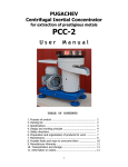
OL1200 consists of control and engine blocks as the standard configuration (See Figure 1-1.) In addition,
the following options are also available.
%1.2 Printer Configuration
1.2 Printer Configuration
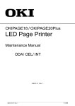
The printer unit consists of the following hardware components:
• Electro-photographic processor
• Paper feeder
• Controller
• Operator panel
• Power/sensor board
Figure 1-2 shows the printer unit configuration.
%1.3 Optional Configuration
1.3 Optional Configuration
The options below are available for use with OL1200. They are sold separately from the printer unit.
(1) Power Envelope Feeder
(2) High Capacity Second Paper Feeder
(3) Font Card
(4) RAM module
• 8MB RAM module
• 16MB RAM module
%1.4 Specification
1.4 Specification
(1) Type Desk top
(2) External dimensions Height 10.6 (270 mm) (excludes protruding Width 14.4 (366 mm) Portion)
Depth 16.9 (430 mm)
(3) Weight 15.2 kg (33.5 lbs)
(4) Development method Dry electrophotography Exposure method LED stationary head
(5) Paper used <Type>
• Standard paper Xerox 4200 (20 lbs)
• Application paper (manual face-up feed) Label Envelope OHP paper (Transparency)
<Size>
• Standard sizes Letter Legal Executive Envelope A4 A5 B5 A6
• Applicable sizes Width: 3.4 to 8.5 (86 to 228 mm) Length: 5.5 to 14 (140 to 355.6
mm) <Thickness> Automatic feed: 16 to 28 lbs (60 to 105 g/m 2 ) Manual feed:
Label, OHP paper (transparency) Envelope
(6) Printing speed
First print: 12 sec.
Continuous print: 12 sheets/min.
Warm-up time: 90 sec. [at room temperature 77°F (25°C) and rated voltage (120 VAC)]
(7) Paper feed method Automatic feed or manual feed
(8) Paper delivery method Face down/face up
(9) Resolution 600 x 600 dots/inch
(10) Power input 120 VAC + 5.5%, 15% (ODA) 230/240 VAC + 10%, 14% (ODA/OEL)
(11) Power consumption
Peak: Approx. 600W
Typical Operation: Approx. 220W
Idle: Approx. 100W
Power save mode: Approx. 20W
(12) Temperature and humidity During operation: 50 to 90°F (10 to 32°C) In storage: 14 to 110°F
(10 to 43°C)
(13) Noise During operation: 50 dB (A) or less At standby: 45 dB (A) or less Power save mode: 43
dB (A) or less
(14) Consumables Toner cartridge kit 5,000 (5% duty) Image drum cartridge 30,000 (at continuous
printing) 20,000 (3 page/job) 15,000 (1 page/job)
%1.5 Safety Standards
1.5 Safety Standards
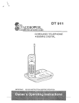
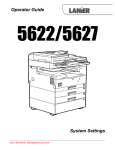
1.5.1 Certification label
The safety certification label is affixed to the printer in the position below.
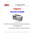
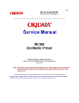
%1.5.2 Warning Label
1.5.2 Warning label
The warning label is affixed to the portion which may cause an injury to human body. Follow the
instructions on warning labels during maintenance.
Chapter 2
%2. Operation Description
2. OPERATION DESCRIPTION
OL1200 consists of a control board, a power supply/sensor board, a driver board, an operator panel and
an electro-photographic process mechanism.
The control board receives data through a host I/F, decodes and edits the data, and stores the edited
data in a memory. After completing edition of one page of data, it references the font memory and
generates bit data on the same memory. At the same time, it transfers the bit image data to an LED head
in units of one dot line.
The electro-photographic process mechanism prints data on paper.
The operator panel is used for operations and status display.
Fig. 2-1 shows an OL1200 block diagram.
%2.1 Main Control Board (Aolm-Pcb)
2.1 Main Control Board (AOLM-PCB)
The control board consists of a one chip CPU, LSIs, a program/font ROM, a DRAM, an EEPROM, a host
interface circuit, and a mechanism driving circuit.
(1) One-chip CPU
The one-chip CPU is a custom CPU (32-bit internal bus, 32-bit external bus, 33-MHz clock) that
incorporates a RISC CPU and its peripheral devices, and has the following functions:
Built-in device
Function
Chip select controller
Bus controller DRAM controller
Control of ROM, DRAM and I/O device
DMA controller
Transfer of image data from DRAM to OST
LSI
Parallel interface controller
Control of Centronics parallel interface
Serial interface controller
Control of RS-232C serial interface
Timer
Generation of various control timing
Monitoring of paper running and paper size
Serial I/O port
Control of operator panel, EEPROM, and
options
I/O port
Inputting/outputting of sensor, signal and
motor signal
Option I/O interface
Control of OKI HSP interface
(2) Program/font ROM
The program/font ROM stores the equipment program and various types of fonts. EPROM/ OTP or
masked ROM is used as an program/font ROM.
(3) Memory
2-Megabyte DRAM (512K x 4) is mounted as resident memory to be used for storing the program and
providing various buffers. This DRAM is expandable up to 34 Mbytes by adding expansion memory
(SIMMs). This DRAM provides the areas shown in the following table.
Memory capacity setting
Memory area
Use
MENU
Expansion RAM
System area
Working area used for the
program
Fixed
Working area
used for the
program
Fixed
Raster buffer
Stores converted bit image data
Enable
Expandable
Receive buffer
Stores temporarily the data
received from the host interface
Enable
Expandable
Page buffer
Adds print information to the
analyzed receive data and stores
the resulted data.
Expandable
DLL/macro buffer
Stores soft fonts and macro data.
Expandable
Font cache buffer
Stores bit map fonts generated by
the font rasterizer based on
scalable font information
Enable
Expandable
(4) EEPROM
The EEPROM has a 4-kbit capacity and stores the following data.
• Menu data
• Various counter data (page counter, drum counter, fuser counter, etc.)
• Adjustment parameters (LED head drive time, print start position, etc.)
(5) LSI (MSM10S0050-015GS)
This LSI is connected to the CPU via the bus as a peripheral device of the CPU and controls the memory
based on the RAS signal and address signal received from the CPU.
(6) LSI (MBCE31701-040FP-BND)
This LSI is used as a peripheral device of the CPU and performs smoothing compensation (OST) of print
image data (300 dpi and 600 dpi). In addition, it transfers serially bit image data for each dot line to the
LED head.
(7) Host interface
This printer has the following interfaces to the host.
• Centronics bidirectional parallel interface
• RS232C serial interface
• OKI HSP interface (Option)
The single effective interface or the automatic interface select mode can be selected using the menu. If
the busy state of the printer continues for a long time period, the buffer near-full control releases the busy
status at constant intervals even if the host side is busy so not to cause the interface time-out at the host
side.
(a) Centronics bidirectional parallel interface
This is an interface conforming to IEEE-1284 and provides either unidirectional or bidirectional
communications according to each of the following communication modes.
• Compatibility mode
Unidirectional communications from the host to the printer.
• Nibble mode
This mode transmits 4-bit wide data from the printer to the host. In this mode, each 1-byte data is
transferred in the form of two nibbles using ERROR, BUSY, FAULT, and SELECT signal leads. This
mode can provide the bidirectional operation in combination with the compatibility mode.
• ECP mode
his mode provides the asynchronous bidirectional interface and transmits and receives 1-byte data
using eight data signal leads under the semi-duplex control by the host.
When the power is turned on, the compatibility mode is automatically selected. The change to another
mode from the compatibility mode is made through negotiation. (When the BI DIRECTION is set to
ENABLE in the menu, this change can be performed.) (For the electrical/physical characteristics of this
interface, see APPENDIX B)
(b) RS232C serial interface
The following protocol is supported for the serial interface conforming to EIA RS232C.
• READY/BUSY (DTR HI or DTR LO)
• X-ON/X-OFF
• RBST X-ON
(For the electrical/physical characteristics of the interface, see APPENDIX A)
(c) OKI HSP interface (Option)
This interface (slot) is an OKI unique universal interface that provides the platform to connect various
boards (including those supplied by third venders) such as the LAN connection expansion board.
Any expansion boards compatible with this interface can be mounted on the Control board without
modifying the program at the printer side. The conceptual diagram of the OKI HSP interface is shown in
Fig. 2-2.
(For the electrical/physical characteristics of the OKI HSP interface, see the OKI HSP interface technical
manual. This manual will not be available to the general public.)
(8) RAM module
• Pin layout
• Basic specificaton
- Type: 72 pins SIIM (32 bits buss width)
- Access time: 60ns, 70ns, 80ns, 100ns
- Capacity: 1, 2, 4, 8, or 16MB (16 MB RAM will not be sold by Okidata)
- Parity: None
%2.2 Power/Sensor Board
2.2 Power/Sensor Board
The power/sensor board consists of an AC filter circuit, a low voltage power supply circuit, a high voltage
power supply circuit, heater drive circuit, and photosensors.
(1) Low voltage power supply circuit
This circuit generates the following voltages.
Output voltage
Use
+5 V Logic circuit supply voltage
+30 V
Motor and fan drive voltage and source voltage for
high-voltage supply
+8 V
RS-232C line voltage
8V
RS-232C line voltage and analog circuit supply
voltage
(2) High voltage power supply circuit
This circuit generates the following voltages necessary for electro-photographic processing from
+30 V according to the control sequence from the control board. When cover open state is
detected, +30 V supply is automatically interrupted to stop the supply of all the high-voltage
outputs.
Output
Voltage
Use
CH
-1.30 KV
Voltage applied to
charging roller
DB
-240 V/+300 V
Voltage applied to
developing roller
SB
-360 V/450 V
Voltage applied to
toner supply roller
TR
+4 KV/-1.3 kV
Voltage applied to
transfer roller
CB
+400 V
Voltage applied to
cleaning roller
Remarks
Variable
(3) Photosensor
The photosensor mounted on this power/sensor board supervises the paper running state during printing.
Figure 2-3 shows the sensor layout diagram.
Sensor
Function
Sensing state
Inlet sensor 1
Detects the leading part of the ON: Paper exists.
paper and gives the
OFF: No paper exists.
supervision timing for
switching from hopping
operation to feeding
opera-tion. Supervises the
paper running state and the
paper size accord-ing to the
paper reach time and running
time.
Inlet sensor 2
Detects the form width.
Paper sensor
Detects the leading part of the ON: Paper exists.
paper. Supervises the paper
OFF: No paper exists.
running state.
Outlet sensor
Supervises the paper feed
and size according to the time
of arrival to the sensor and
the time of passage of paper.
ON: Paper exists.
OFF: No paper exists.
Paper end sensor
Detect the end of the paper.
ON: Paper exists.
OFF: No paper exists.
Toner low sensor
Detects the lack of toner.
ON long: Toner low exists
OFF short: No Toner low
exists
ON: A4 or larger
OFF: Smaller than A4
%2.3 Relay/Driver Board (Aolc Board)
2.3 Relay/Driver Board (AOLC board)
This board relays signals between the Control board and the Power/Sensor board and includes the
registration motor and drum motor driver IC.
%2.4 Electro-Photographic Process
2.4 Electro-photographic Process
2.4.1 Electro-photographic process mechanism
This mechanism prints image data from the control board on the paper by electro-photographic process.
The Figure 2-4 shows the layout of the electro-photographic process mechanism.
(1) Image drum unit
The image drum unit consists of a sensitive drum, a charger, and a developer. The unit forms a
toner image on the sensitive drum, using a electrostatic latent image formed by the LED head.
(2) Hopping motor
This motor is a pulse motor of 48 steps/rotation that is two-phase excited by the signal from the
control board. It drives the hopping roller of the first tray and the front feed roller via two one-way
clutches according to the direction of rotation.
(3) Registration motor
This motor is a pulse motor of 48 steps/rotation that is two-phase excited by the signal from the
control board. It drives the registration roller.
(4) Drum motor
This drum motor is a pulse motor of 48 steps/rotation that is two-phase excited by the signal from
the control board and is the main motor of this mechanism.
(5) LED head
Image data for each dot line from the control board is received by the shift register and latch
register. The 5120 LEDs are driven to radiate the image data to the image drum.
(6) Fuser
The fuser consists of a heater, a heat roller, a thermistor and a thermostat. An AC voltage from the
power supply board is applied to the heater under the control of the HEATON signal from the
control board. This AC voltage heats the heater. The control board supervises the heat roller
temperature via the thermistor, and regulates the heater roller at a predetermined temperature
(185 ~ 188°C) by connecting or disconnecting the AC voltage supply to the heater. If the heater
roller temperature rises abnormally, the thermostat of the heater voltage supply circuit is activated
to cut the AC voltage supply forcibly.
%2.4.2 Electro-Photographic Process
2.4.2 Electro-photographic process
The electro-photographic processing is outlined below. Figure 2-5 shows the electro-photo-graphic
printing process.
1 Charging
The surface of the image drum is uniformly charged with negative charges by applying a negative
voltage to the charge roller.
2 Exposure
Light emitted from the LED head irradiates the negatively charged surface of the image drum. The
surface potential of the irradiated part of the image drum surface is lowered, so that an
electrostatic latent image associated with the print image is formed.
3 Developing and toner recovery
When the negatively charged toner is brought into contact with the image drum, it is attracted to the
electrostatic latent image by static electricity, making the image visible. At the same time, the
residual toner on the image drum is attracted to the developing roller by static electricity.
4 Transfer
When paper is placed over the image drum surface and a positive charge, opposite in polarity to the
toner, is applied to the reverse side of the paper from the transfer roller, the toner is attracted by
the positive charge and is transferred to the paper. As a result, the toner image formed on the
image drum is transferred to the paper.
5 Temporary cleaning
Residual toner that remains on the image drum without being transferred is made uniform by the
cleaning roller and is temporarily attracted to the cleaning roller by static electricity.
6 Fusing
The toner image transferred to the paper is fused under heat and pressure. Figure 2-6 shows an
electro-photographc process timing chart.
%2.4.3 Process Operation Descriptions
2.4.3 Process operation descriptions
(1) Hopping
Hopping from the first tray and the front feeder are effected by a single hopping motor in the
mechanism shown below.
Turning the Hopping motor in the a direction drives the hopping roller of the first tray. Turning the Hopping
motor in the b direction drives the Hopping roller of the front feeder. The both and hopping gears contain
one-way bearing, so that turning each of these gears in reverse direction will not be transmitted to the
corresponding roller.
(a) Hopping (1st tray)
1 Rotating the pulse motor in the direction a (Clock-wise direction) drives the hopping roller of the
first tray to advance the paper until the inlet sensor turns on. At the same time, the one-way
clutch gear B also rotates. However, the hopping roller of the front feeder will not rotate due to the
one-way bearing.
2 After turning on the inlet sensor, the paper advances further by a predetermined length until it hits
the registration roller. (The skew of the paper can thus be corrected.)
(b) Hopping (front feeder)
1 Rotating the pulse motor in the direction b (Counter Clock-wise direction) drives the hopping roller
of the front feeder to advance the paper until the inlet sensor turns on. At the same time, the
one-way clutch gear A also rotates. However, the hopping roller of the 1st tray will not rotate due
to the one-way bearing.
A cam to push down the front feeder plate is attached on each of the ends of the hopping roller
shaft. These cams push down the front feeder plate when the hopping operation is not performed
so as to facilitate the setting of paper into the tray. A microswitch is provided under the front
feeder plate to detect that the front feeder plate is at the lower position. When the front feeder
plate is at the lower position, this microswitch causes the motor to stop.
2 After turning on the inlet sensor, the paper advances further by a predetermined length until it hits
the registration roller. (The skew of the paper can thus be corrected.)
%(2) Feeding
(2) Feeding
After the end of hopping, the pulse motor drives the registration roller. The registration roller
advances the paper until it comes out of the registration roller.
When leading edge of the paper causes the paper sensor to turn on, the printing is started
synchronously.
%(3) Charging
(3) Charging
Charging is effected by applying a DC minus voltage to the charge roller that is in contact with the image
drum surface.
%(4) Exposure
(4) Exposure
Light emitted from the LED head irradiates the image drum surface with negative charges. The surface
potential of the irradiated part of the image drum drops, thereby forming an electrostatic latent image
associated with the image signal.
%(5) Developing
(5) Developing
Toner is attracted to the electrostatic latent image on the image drum surface to convert it into a
visible toner image. Developing takes place at the contact between the image drum and the
developing roller.
1 As the toner supply roller rotates while rubbing on the developing roller, a friction charge is
generated between the developing roller and the toner, allowing the toner to be attracted to the
developing roller. (The developing roller surface is charged positive and the toner, negative.)
2 The toner attracted to the developing roller is scraped off by the doctor blade, forming a thin coat
of toner on the developing roller surface.
3 Toner is attracted to the exposed part (low-potential part) of the image drum at the contact
between the image drum and the developing roller, making the electrostatic latent image visible.
%(6) Transfer
(6) Transfer
The transfer roller is composed of conductive sponge material and is designed to make the image
drum surface and the paper closely into contact.
Paper is placed over the image drum surface, and a positive charge, opposite in polarity to the
toner, is applied to the paper from its reverse side.
The application of a high positive voltage from the power supply to the transfer roller causes the
positive charge induced to the transfer roller surface to be transferred to the paper at the contact
between the transfer roller and the paper. As a results, toner charged negative that is attracted to
the image drum surface is transferred to the upper side of the paper by the positive charge on the
lower side of the paper.
%(7) Fusing
(7) Fusing
After the end of the transfer, the unfused toner image is fused on the paper under heat and
pressure as it passes between the heater roller and the back-up roller. The heater roller with a
Teflon coating incorporates a 400W heater (Halogen lamp), which heats the heat roller.
A thermistor which is in contact with the heater roller regulates the heater roller at a predetermined
temperature (about 185 ~ 188°C). A safety thermostat cuts off voltage supply to the heater by
opening the thermostat in the event of abnormal temperature rises.
The back-up roller is held under a pressure of 2.5 kg from the pressure spring at each side.
%(8) Cleaning
(8) Cleaning
After the end of the transfer, residual toner on the image drum is attracted to the cleaning roller
temporarily by static electricity to clean the image drum surface.
%(9) Cleaning Of Rollers
(9) Cleaning of rollers
The charge roller, transfer roller and cleaning roller are cleaned in the following cases:
• In warming up at power-on time
• In warming up after the cover is opened and closed
• When the number of accumulated sheets is 10 or more and the printout operation ends
Changes in bias voltage applied to each roller move adhesive toner from the roller to the image
drum and return it to the developer.
%2.5 Paper Jam Detection
2.5 Paper Jam Detection
The paper jam detection function supervises the paper state at power-on time and during printing. In the
event that a jam occurs, this function interrupts the printing process. If any of the following errors is
presented, recovery printing will be performed by removing the jammed paper ( by opening the upper
cover, removing the jammed paper and closing the upper cover).
Error
Cause of error
Paper input jam
• At power-on time, the paper is placed at the inlet sensor.
• After hopping operation is attempted three times, the leading part of
the paper does not reach the inlet sensor.
Paper feed jam
• At power-on time, the paper is placed at the paper sensor.
• The leading part of the paper does not reach the paper sensor within
a predetermined distance after the paper has reached the inlet sensor.
• The trailing part of the paper does not pass over the paper sensor
within a predetermined distance after the leading edge of the paper
has passed over the paper sensor.
• The leading part of paper does not reach the outlet sensor within a
predetermined distance after the paper has reached the paper sensor.
Paper exit jam
• At power-on time, the paper is placed on the outlet sensor.
• The paper does not pass over the outlet sensor within a
predetermined time after the leading part of the paper has reached the
outlet sensor.
• The paper size check with the manual feed specified considers the
reference size as free size.
Paper size error
Paper size error
• The size of the paper is supervised by the inlet sensor
1. It is detected that the paper does not pass over the inlet sensor 1
within predetermined range of distance.
• The inlet sensor 2 detects that the size of the loaded paper is A4 or
larger, or smaller than A4. The detected paper size differs from the
paper size set by command or menu.
• The paper size check with the manual feed specified considers the
reference size as free size.
%2.6 Cover Open
2.6 Cover Open
When the stacker cover is opened, the cover open microswitch on the power/sensor board is turned off to
cut the supply of +30V to the high voltage power supply circuit. As a result, all high-voltage outputs are
interrupted. At the same time, the CVOPN signal is sent to the control board to notify it of the off state of
the microswitch, and the control board performs the cover open processing.
%2.7 Toner Low Detection
2.7 Toner Low Detection
• Composition
The device consists of the stirring gear which rotates at a constant rate, the stirring bar and the
magnet on the stirring bar. The stirring bar rotates through the link on the protrusion in the stirring
gear.
Toner Low is detected by monitoring the time interval of the encounter of the magnet set on the sensor
lever and the magnet on the stirring bar.
Operation during toner full state
• The stirring bar rotates due to the interlocking with the stirring gear.
• Even when the magnet on the stirring bar reaches the maximum height, since the other side is
being dipped in the toner, the stirring bar is pushed by the stirring gear.
• Operation
Operation during toner low state
• When the stirring bar reaches the maximum height, since there is no resistance provided by the
toner on the other side, it falls to the minimum height due to its own weight. Be-cause of this, the
time interval during which it is in encounter with the magnet of the sensor lever becomes long. By
monitoring this time interval, toner low can be detected.
TONER FULL state
TONER LOW state
• When the toner low state is detected 2 times consecutively, Toner Low is established.
• When the toner full state is detected 2 times consecutively, Toner Low is cancelled.
• When there is no change with the toner sensor for 2 cycles (5.8 sec. x 2) or more, then the Toner
Sensor Alarm is activated.
• The toner sensor is not monitored while the drum motor is in halt.
%2.8 Stacker-Full Detection
2.8 Stacker-full Detection
The sensor lever at the paper outlet to the stacker detects a stacker-full state (about 250 sheets) and
stops printing of the ensuing pages.
%2.9 Page Size Detection
2.9 Page Size Detection
The four tab pieces are driven according to the setting position of the paper guide through the cam
interlocked with the paper guide of the paper cassette.
When the paper cassette is inserted into the printer, the state of the tab pieces is detected by the
microswitch to recognize the paper size.
State of Microswitches
SW1
SW2
SW3
SW4
Paper size
0
1
1
1
Letter
0
1
0
1
Executive
0
0
1
1
A4
1
1
1
0
Legal 14
1
0
1
1
Legal 13
1
1
0
1
B5
1
1
0
0
A5
1
0
0
1
A6
Chapter 3
3. Parts Replacement
3. PARTS REPLACEMENT
The section explains the procedures for replacement of parts, assemplies, and units in the field. Only the
removal procedures are explained here. Reverse the procedure for the installation.
%3.1 Precautions For Parts Replacement
3.1 Precautions for Parts Replacement
Always practice good Anti-Static procedures when handling equipment. (1) Before starting parts
replacement, remove the AC cable and interface cable.
(a) Remove the AC cable in the following procedure:
i) Turn off ("o") the power switch of the printer
ii) Disconnect the AC inlet plug of the AC cable from the AC receptacle.
iii) Disconnect the AC cable and interface cable from the printer.
(b) Reconnect the printer in the following procedure.
i) Connect the AC cable and interface cable to the printer.
ii) Connect the AC inlet plug to the AC receptacle.
iii) Turn on ("l") the power switch of the printer.
(2) Do not try disassembly as long as the printer is operating normally.
(3) Do not remove unnecessary parts: try to keep disassembly to a minimum.
(4) Use specified service tools.
(5) When disassembling, follow the determined sequence. Otherwise, parts may be damaged.
(6) Since screws, collars and other small parts are likely to be lost, they should temporarily be
attached to the orginal positions.
(7) When handling ICs such as microprocessors, ROM and RAM, and circuit boards, always
practice good anti-static procedures.
(8) Do not place printed circuit boards directly on the equipment or floor.
%[Service Tools]
[Service Tools]
Table 3-1 shows the tools required for field replacement of printed circuit boards and units.
Table 3-1 Service Tools
3.2 Parts Layout 1- 4
3.2 Parts Layout 1 - 4
%Parts Layout 2 - 4
Parts Layout 2 - 4
%Parts Layout 3 - 4
Parts Layout 3 - 4
%Parts Layout 4 - 4
Parts Layout 4 - 4
%3.3 How To Change Parts
3.3 How to Change Parts
This section explains how to change parts and assemblies appearing in the disassembly diagram below.
%3.3.1 Rear Cover, Side Cover (L) Assy, Face-Up Stacker Assy, And
I/F Cover Assy.
3.3.1 Rear cover, side cover (L) Assy, face-up stacker Assy, and I/F cover Assy.
(1) Turn the AC power switch off. Unplug the AC power cord from the outlet.
(2) Remove the interface cable 1. Remove drum/toner Assy 2A and store in black plastic bag
shipped w/printer.
(3) Open the face-up stacker Assy 8. Disconnect the engagement at the left and right protrusions
8A . Remove the face-up stacker Assy 8. (Flex the Assy 8 in the middle to disengage 8A from
the Rear cover 0.)
(4) Open the stacker cover 2 and the manual feed hopper Assy3. Remove three screws 4. Remove
the side cover (L) Assy 5.
(5) Remove two screws 6. Remove the I/F cover Assy 7.
(6) Remove two screws 9 and four claws A. (Use a small flat blade screw driver to "pop" claws.)
Remove the rear cover 10.
%3.3.2 Contact Assy
3.3.2 Contact Assy
(1) Turn the AC power switch off. Unplug the AC power cord from the outlet.
(2) Remove the side cover (L) Assy (see 3.3.1 (1) to (4)).
(3) Remove two screws 1. Remove the contact plate (cover) 2 and the contact Assy 3. Pull bottom
of Assy 3 out first, then the top of Assy. Remove fan connector cables from location 4.
Caution: Be careful not to deform the electrodes of the contact Assy when removing the contact
Assy.
%3.3.3 Dc Fan Motor
3.3.3 DC fan motor
(1) Turn the AC power switch off. Unplug the AC power cord from the outlet.
(2) Remove the side cover (L) Assy (see 3.3.1 (1) to (4)).
(3) Unplug the connector of the DC fan motor 1 and remove the DC fan motor 1.
%3.3.4 Manual Feed Hopper Assy
3.3.4 Manual feed hopper Assy
(1) Turn the AC power switch off. Unplug the AC power cord from the outlet.
(2) Open manual feed hopper Assy 1. Disengage the lower portion of this Assy.
(3) Hold manual feed hopper Assy 1 vertically and remove the left and right levers 2 with a
downward motion.
%3.3.5 Side Cover (R) (Operator Panel Assy)
3.3.5 Side cover (R) (operator panel Assy)
(1) Turn the AC power switch off. Unplug the AC power cord from the outlet.
(2) Remove interface cable 1.
(3) Open stacker cover 2. Remove two screws 3. Remove I/F cover Assy 4.
(4) Remove two screws 5 and flexible cable 6 (use care to not damage flexible cable). Remove
operator panel Assy 7.
(5) Open manual feed hopper Assy 8. Remove three screws 9 and then remove side cover (R) 10.
%3.3.6 Earth Plate Bk (R) (Aolm-Pcb, Ic Cover)
3.3.6 Earth plate BK (R) (AOLM-PCB, IC cover)
(1) Turn the AC power switch off. Unplug the AC power cord from the outlet.
(2) Remove side cover (R) (see 3.3.5).
(3) Remove five screws 1 and eight connectors 2. Remove AOLM-PCB 3.
(4) Remove two screws 4 Remove IC card cover 5.
(5) Remove four screws 6. Remove side plate (R) 7, by pulling up and out on top part of plate.
(6) Remove the claws and then remove FG plate BK (R) 8.
%3.3.7 Stacker Cover Assy, Damper Arm, And Washer
3.3.7 Stacker cover Assy, damper arm, and washer
(1) Turn the AC power switch off. Unplug the AC power cord from the outlet.
(2) Remove the rear cover (see 3.3.1).
(3) Remove the side cover (R) (see 3.3.5).
(4) Remove the side plate (R) (see 3.3.6 (1) to (5)).
(5) Disconnect the backup roller release lever 1 with the protrusion on the out side surface of the
right side of the stacker cover.
(6) Remove screw 2 and washer 3. Remove two claws. Remove stacker cover Assy 4 (at this time,
the damper arm 5 is also removed).
%3.3.8 Damper
3.3.8 Damper
(1) Turn the AC power switch off. Unplug the AC power cord from the outlet.
(2) Remove the damper arm (see 3.3.7).
(3) Remove two screws 1 and then remove two dampers 2.
%3.3.9 Stacker Full Sensor Assy
3.3.9 Stacker full sensor Assy
(1) Turn the AC power switch off. Unplug the AC power cord from the outlet.
(2) Remove the stacker cover Assy (see 3.3.7).
(3) Remove four screws 1. Remove stacker mount 2 by releasing the tabs at position 2A
(4) Remove stacker full sensor Assy 3 by spreading the plastic tabs on each side of sensor Assy 3
and lifting switch from cover.
%3.3.10 Cable Cover (Cable Guides A And B)
3.3.10 Cable cover (cable guides A and B)
(1) Turn the AC power switch off. Unplug the AC power cord from the outlet.
(2) Remove the stacker cover Assy (see 3.3.7).
(3) Remove two screws 1 release tabs at position 1A . Remove cable cover 2, cable guide A 3.
%3.3.11 Eject Roller Assy
3.3.11 Eject roller Assy
(1) Turn the AC power switch off. Unplug the AC power cord from the outlet.
(2) Remove the rear cover (se 3.3.1).
(3) Remove the side cover (R) (see 3.3.5).
(4) Remove the side plate (R) (see 3.3.6 (1) to (5)).
(5) Remove the stacker cover Assy (see 3.3.7).
(6) Release the latch on the right side of eject roller Assy 1. Lift up and remove the eject roller Assy.
%3.3.12 Paper Supply Guide D
3.3.12 Paper supply guide D
(1) Turn the AC power switch off. Unplug the AC power cord from the outlet.
(2) Remove the side cover (R) (see 3.3.5).
(3) Remove four screws 1. Lift up and remove front feeder roller Assy 2.
(4) Lift up and remove paper supply guide D 3. (At this time, two bias rollers 4 are also removed. Be
careful not to lose them.)
(5) Remove bias spring 5 from the paper supply guide D 3.
%3.3.13 Separator F
3.3.13 Separator F
(1) Turn the AC power switch off. Unplug the AC power cord from the outlet.
(2) Remove the manual feed hopper Assy (see 3.3.4).
(3) Remove the side cover (R) (see 3.3.5).
(4) Remove the front feeder Assy (see 3.3.12 steps (1) to (3)). Make a diagram of wire locations
and routing.
(5) Remove two screws 1 and then remove the inner cover 2. At this time, the cover lock lever 3
and the torsion spring 4 are also removed. Note position of torsion spring.
(6) Remove two screws 5 and then remove square-shaped connector 6.
(7) Using great care, remove the connector of switch Assy 7 from square-shaped connector 6.
(8) Turn idle gear 8 in the direction of arrow A until front feeder plate 9 is elevated.
(9) Remove front feeder gear 10 and then remove two springs A. Be careful not to lose the springs.
(10) Remove four screws B and then remove paper supply guide C. (At this time, front feeder earth
plates D, G, and H are also removed.)
(11) Remove front feeder plate 9 by releasing the engagement at two parts 9A . Switch Assy 7 may
now be removed.
(12) Pull up separator E toward you and then release two mounting posts at 15A to remove the
separator. (At this time, two springs F are also removed. Be careful not to lose the springs.)
(13) Release two mounts on paper supply guide C and pull out switch Assy 7 upward.
During Re-assembly use great care: do not pinch, crimp, or cut wires to switch Assy 7.
%3.3.14 Front Feeder Roller Assy
3.3.14 Front feeder roller Assy
(1) Turn the AC power supply switch off. Unplug the AC power cord from the outlet.
(2) Remove the manual feed hopper Assy (see 3.3.4).
(3) Remove the side cover (R) (see 3.3.5).
(4) Remove the front feeder roller Assy (see 3.3.12 (1) to (3).
(5) Remove the paper supply guide A (see 3.3.13 (1) to (10)).
(6) Remove idle gear 1 and then remove the right side front feeder cam 2, release lever (R) 3, and
spring 4. (At this time, knock pin 5 and bearing F are also removed. Be careful not to lose them.)
Do not mix these parts with those from the left side of Assy.
(7) Pull out the front feeder 7 shaft toward the left and then remove front feeder roller Assy 8.
(8) Remove knock pin 9 and then remove front feeder cam D on the left (L) side, release lever (L) A,
and spring B. (At this time, the bearing C on the left (L) side is also removed.) Do not mix these
parts with those from the right side of Assy.
Note
1: Hopping roller orientation when removed from shaft.
2: Be sure sensor arm swings freely after re-assembly.
3: Be sure that during re-assembly both feeder cams (2 and D) are facing the same direction.
%3.3.15 Hopping Motor
3.3.15 Hopping motor
(1) Turn the AC power switch off. Unplug the AC power cable from the outlet.
(2) Remove the manual feed hopper Assy (see 3.3.4).
(3) Remove the side cover (R) (see 3.3.5).
(4) Remove the front feeder Assy (see 3.3.12.(1) to (3)).
(5) Remove the inner cover and square-shaped connector (see 3.3.13.(5) and (6)).
(6) Remove hopping motor 1 from the square-shaped connector.
(7) Remove the paper supply guide A (see 3.3.13. (7) to (10)).
(8) Remove the lever (R) (see 3.3.10. (6)).
(9) Remove two screws 2 and then remove side plate (R) Assy 3.
(10) Remove two screws 4 and then remove hopping motor 1.
%3.3.16 Front Feeder Paper End Sensor
3.3.16 Front feeder paper end sensor
(1) Turn the AC power switch off. Unplug the AC power cord from the outlet.
(2) Remove the manual feed hopper Assy (see 3.3.4).
(3) Remove the side cover (R) (see 3.3.5).
(4) Remove the front feeder roller Assy (see 3.3.12. (1) to (3)).
(5) Remove the side plate (R) Assy (see 3.3.15. (1) to (9)).
(6) Remove the connector of front feeder paper end sensor 1 from the square-shaped connector.
(7) Remove two screws 2 and then remove paper supply guide C (3).
(8) Remove paper supply guide B (4).
(9) Remove four claws and then remove front feeder paper end sensor 1.
(10) Remove two screws 5 and then remove square-shaped connector 6 from paper supply guide C
(3).
Note: Use great care when removing the sensor.
%3.3.17 Main Chassis Unit
3.3.17 Main chassis unit
(1) Turn the AC power switch off. Unplug the AC power cord from the outlet.
(2) Remove the rear cover (see 3.3.1).
(3) Remove the contact Assy (see 3.3.2).
(4) Remove the side cover (R) (see 3.3.5).
(5) Remove the side plate (R) (see 3.3.6 (1) to (5)).
(6) Remove the stacker cover Assy (see 3.3.7).
(7) Remove the front feeder roller Assy (see 3.3.12, (1) to (3)). At this time, it is not required to
remove the manual feed hopper Assy.
(8) Remove the earth plate (HP).
(9) Lift gear (TR) 1 to unlock it. Remove gear (TR) 1 and transfer roller 2. (At this time, two bearings
(TR) 3 and two transfer springs 4 are also removed.) NOTE: Do not lose bearings or springs.
(10) Remove connector cover 5 in direction of arrow and then remove two connectors 6 and 7.
(11) Remove the DC Fan motor.
(12) Remove eight screws10 and then remove main chassis unit A.
%3.3.18 Registration Roller
3.3.18 Registration roller
(1) Turn the AC power switch off. Unplug the AC power cord from the outlet.
(2) Remove the front feeder roller Assy (see 3.3.12. (1) to (3)).
(3) Remove four screws 1. Lift and remove the registration roller Assy 2, left side first then right
side.
(4) Release the latch and remove registration roller gear 3 and pressure roller gear 4.
(5) Remove left and right side registration roller bearing Assys 5 and then remove resist roller 6 and
pressure roller 7.
%3.3.19 Drum Motor
3.3.19 Drum motor
(1) Turn the AC power switch off. Unplug the AC power cord from the outlet.
(2) Remove the main chassis unit (see 3.3.17).
(3) Remove the registration roller Assy (see 3.3.18 (1) to (3)).
(4) Remove fuser Assy.
(5) Release the latch of fuser pressure roller release lever 1 and pull out it toward the right. (At this
time, idle gear H (2) is also removed.)
(6) Remove spring 3 and then remove pressure release lever 4. Be careful, do not lose or damage
spring.
(7) Remove EP lock spring 5 and then remove ED lock lever 6.
(8) Release two latches and remove motor Assy 7.
(9) Remove two screws 8 and then remove drum motor 9 and heat sink.
(10) Remove two screws 10 and then remove registration motor A.
%3.3.20 Idle Gear
3.3.20 Idle gear
(1) Turn the AC power switch off. Unplug the AC power cord from the outlet.
(2) Remove the main chassis unit (see 3.3.17).
(3) Remove the motor Assy (see 3.3.19 (1) to (8)).
(4) Remove three screws 1 and then remove motor bracket B (2).
(5) Remove idler gear E (3), idle gear D (4), idle gear B (5), idle gear C (6), idle gear A (7), and two
resist idle gears 8.
%3.3.21 Fusing Assy
3.3.21 Fusing Assy
(1) Turn the AC power switch off. Unplug the AC power cord from the outlet.
(2) Remove the side cover (L) Assy (see 3.3.1 (1) to (3)).
(3) Unplug connector 1.
(4) Remove four screws 2 and then remove fusing Assy 3.
%3.3.22 Fuser Pressure Roller
3.3.22 Fuser pressure roller
(1) Turn the AC power switch off. Unplug the AC power cord from the outlet.
(2) Remove the main chassis unit (see 3.3.17).
(3) Remove the fusing Assy (see 3.3.21).
(4) Remove the fuser pressure roller release lever (see 3.3.19 (5)).
(5) Remove two screws 2 and release three locks on the fusing guide. Remove the fusing guide 1
by pushing it upward from the lower side.
(6) Release the engagement with earth plate L (BK) 3. Lift and remove backup roller 4. (At this time,
two backup roller bearings 5 and two bias springs 6 are also removed.)
%3.3.23 Ep Lock Shaft
3.3.23 EP lock shaft
(1) Turn the AC power switch off. Unplug the AC power cord from the outlet.
(2) Remove the main chassis unit (see 3.3.17).
(3) Remove screw 1. Turn EP lock level (L) Assy 2 in the direction of arrow A .
(4) Remove spring 3.
(5) Drop EP lock shaft 4 down and turn in the direction of arrows B and remove it.
%3.3.24 Hopping roller Assy
3.3.24 Hopping roller Assy
(1) Turn the AC power switch off. Unplug the AC power cord from the outlet.
(2) Remove the main chassis unit (see 3.3.17).
(3) Release the latch. Remove hopping roller gear 1 and bearing P 2. Then, remove idle gear HF 3.
(4) Remove the left side of hopping roller shaft 4 from the groove. Pull out hopping roller shaft 4 and
hopping roller Assy 5 toward the left..
(5) Release the latch and remove bearing L 6.
(6) Release the latch and remove hopping roller Assy 5. (At this time, knock pin 7 is also removed.
Be careful not to lose the knock pin.)
%3.3.25 Outlet sensor lever
3.3.25 Outlet sensor lever
(1) Turn the AC power switch off. Unplug the AC power cord from the outlet.
(2) Remove the main chassis unit (see 3.3.17).
(3) Press the clamp part of outlet sensor lever 1. Remove the outlet sensor lever 1 by pushing it
upward from the lower side.
%3.3.26 Toner sensor lever
3.3.26 Toner sensor lever
(1) Turn the AC power switch off. Unplug the AC power cord from the outlet.
(2) Remove the main chassis unit (see 3.3.17).
(3) Squeeze the clamp part of toner sensor lever 1 and remove the toner sensor lever 1 by pushing
it upward from the lower side.
%3.2.27 Paper sensor lever
3.2.27 Paper sensor lever
(1) Turn the AC power switch off. Unplug the AC power cord from the outlet.
(2) Remove the main chassis unit (see 3.3.17).
(3) Squeeze the clamp part of the paper sensor lever 1. Remove the paper sensor lever 1 by
pushing it upward from the lower side.
%3.3.28 Inlet sensor lever
3.3.28 Inlet sensor lever
(1) Turn the AC power switch off. Unplug the AC power cord from the outlet.
(2) Remove the main chassis unit (see 3.3.17).
(3) Squeeze the clamp part of two inlet sensor levers 1. Remove the inlet sensor levers 1 by
pushing them downward.
%3.3.29 Insulator
3.3.29 Insulator
(1) Turn the AC power switch off. Unplug the AC power cord from the outlet.
(2) Remove the main chassis unit (see 3.3.17).
(3) Remove two screws 1 and then remove inlet holder 2. At this time, remove inlet 3 from inlet
holder 2.
(4) Remove eight screws 4, connector 5, and two screws 6. Remove Power/sensor PCB 7 together
with AOLC-PCB 8.
(5) Unplug connector 9 and remove Power/sensor PCB 7.
(6) Remove insulator B .
Caution: Be careful not to deform the paper end lever A.
%3.3.30 Paper end lever
3.3.30 Paper end lever
(1) Turn the AC power switch off. Unplug the AC power cord from the outlet.
(2) Remove the main chassis unit (see 3.3.17).
(3) Release the lock and remove paper end lever 1.
%3.3.31 Guide rail (L) Assy
3.3.31 Guide rail (L) Assy
(1) Turn the AC power switch off. Unplug the AC power cord from the outlet.
(2) Remove the main chassis unit (see 3.3.17).
(3) Remove the insulator (see 3.3.29).
(4) Remove screw 1 and then remove base plate 2.
(5) Remove two screws 3 and then remove guide rail (L) Assy 4.
(6) Remove cassette lock spring 5 and then remove bias link 6 and pull block 7. (Pay attention the
direction of hook of cassette lock spring 5.)
(7) Remove spring 8 and then remove cassette stopper 9.
(8) Remove screw 10 from bias link 6 and then remove link support A.
%3.3.32 Guide rail (R) Assy
3.3.32 Guide rail (R) Assy
(1) Turn the AC power switch off. Unplug the AC power cord from the outlet.
(2) Remove the main chassis unit (see 3.3.17).
(3) Remove the insulator (see 3.3.29).
(4) Remove screw 1 and then remove base plate 2.
(5) Remove two screws 3 and then remove guide rail (R) Assy 4.
(6) Remove cassette lock spring 5 and then remove bias link 6 and pull block 7 (At this time, earth
plate 8 is also removed.) (Pay attention the direction of hook of cassette lock spring 5.)
(7) Remove spring 9 and then remove cassette stopper 10.
(8) Remove screw A and then remove detector spring B.
(9) Remove screw C and then remove AOLS-PCB D.
(10) Remove screws E from bias link 6 and then remove link support F.
(11) Remove two screws G and then remove square cord from square-shaped connector H.
(12) Using great care, remove connector cord I from square-shaped connector H.
%3.3.33 IC card cover
3.3.33 IC card cover
(1) Turn the AC power switch off. Unplug the AC power cord from the outlet.
(2) Remove interface cable 1.
(3) Open stacker cover 2. Remove two screws 3 and then remove IC card cover 4.
%3.3.34 LED head
3.3.34 LED head
(1) Turn the AC power switch off. Unplug the AC power cord from the outlet.
(2) Open stacker cover 1.
(3) Remove PC connectors 2 and two LED cables 3 from LED head 4.
(4) Push the hook on the left side of stacker cover 1 in the direction of arrow and remove LED head
4. (Take care not to lose head springs.)
(5) Pull out the head spring 5 from the post.
%3.3.35 Separator Assy
3.3.35 Separator Assy
(1) Turn the AC power switch off. Unplug the AC power cord from the outlet.
(2) Pull out the paper cassette Assy 1 from the printer.
(3) Release two locks and remove separator Assy 2. (At this time, leaf spring 3 and coil spring 4 are
also removed. Be careful not to lose these springs.)
%3.3.36 Transfer roller
3.3.36 Transfer roller
(1) Turn the AC power switch off. Unplug the AC power cord from the outlet.
(2) Open stacker cover 1.
(3) Lift the left side of the gear TR 2 and release the lock. Remove gear TR 2 and transfer roller 3.
(At this time, two bearings (TR) 4 and two transfer roller springs 5 are also removed.)
(4) Remove diselectrification bar 6 and diselectrification film 7 from the chassis unit.
Chapter 4
4. Adjustment
4. ADJUSTMENT
This chapter explains the adjustment necessary when replacing a part. Adjustment is made by
changing a parameter value set in EEPROM on the controller PCB. A parameter is set with the
use of the keys on the operator panel. This printer has three kinds of maintenance mode. You will
utilize one of the maintenance modes when replacing key parts.
%4.1 Maintenance Modes And Functions
4.1 Maintenance Modes And Functions
• User maintenance mode
To enter the user maintenance mode, turn on the POWER switch while pressing the MENU key.
Function
There are six functions as follows.
• Menu reset
• Hex dump
• Drum counter reset
• Operator panel menu disable
• X adjust
• Y adjust
• System maintenance mode
Note: This mode is used only by service persons and it should not be released to the end-users.
To enter the system maintenance mode, turn on the POWER switch while pressing the RECOVER
key.
Function
There are five functions as follows.
• Page count display
• Loop test
• Page count printing enable/disable
• EEPROM reset
• Rolling ASCII continus prinitng
• Engine maintenance mode
Note: This mode is used only by service persons and it should not be released to the end-users.
To enter the engine maintenance mode, turn on the POWER switch while pressing the FORM
FEED key and ENTER key.
Function
There are 13 functions as follows.
• Head drive time setting
• Printing start position setting
• Drum counter total display
• Drum count display
• Setting of standard paper feed length
• Setting of front feeder paper feed length
• Setting of second tray paper feed length
• Selection of second tray feeder download table
• Setting of envelope feeder paper feed length
• Selection of envelope feeder download table
• Fuser count indication
• Fuser count reset
• Engine reset
%4.1.1 User maintenance mode
4.1.1 User maintenance mode
• To enter the user maintenance mode, turn the power supply ON while pressing the Menu key.
• This mode uses the menu for function selection.
• The user maintenance mode provides the following functions:
(1) Menu reset
• All settings for Menu level-1 are reset to the factory default values. The menus for all executable
emulations including options are reset to the factory default values.
• The operation mode starts automatically upon completion of resetting.
(2) Hex dump
• The data received from the host is dumped in hexadecimal notation to the printer.
• Printing is activated automatically when the received data exceeds one page. If the received data
is less than one page, printing can be activated manually be pressing the Form Feed key after
selecting the OFF LINE. (Automatic activation of printing even when the received data is less
than one page by selecting the Auto Eject function on the menu.)
• To exit from this mode is turning the power OFF.
(3) Drum counter reset
• This function resets the drum life data when the user replaces the image drum unit.
• The operation mode starts automatically upon completion of resetting.
(4) Operator panel menu disable
• This function is for enabling and disabling the operator panel menu functions (Menu 1, Menu 2,
Tray Select, Copies and Paper Size).
(5) X ADJUST
• This function is used to adjust the printing start position within the range of ±2 mm in 0.25 mm
steps in the X direction.
(6) Y ADJUST
• This function is capable to adjust the printing start position within the range of ±2 mm in 0.25 mm
steps in the Y direction.
%User maintenance mode menu system
User maintenance mode menu system
%4.1.2 System maintenance mode
4.1.2 System maintenance mode
• The system maintenance mode is set when the power is turned ON while pressing the Recover
key.
• This mode adopts the menu for function selection.
• The system maintenance mode is provided with the following functions:
(1) Page count display
• The total number of pages counted at the engine is displayed on the LCD.
(2) Page count printing enable/disable
• This function selects whether to include (enable) or exclude (disable) the total number of printed
pages counted at the engine at the time of menu printing.
(3) Rolling ASCII continuous printing
• The rolling ASCII pattern is printed continuously for various engine tests.
• Press the ON-LINE key to cancel this mode.
(4) Loop test
• The loop test is for testing the serial I/F functions without connecting the printer to a host.
• The data is sent and received by loop back in the loop test.
• The loop test is performed even when any other interface is selected in Menu level-2.
• Installation of the loop connector* is necessary for the loop test.
• The loop count is displayed in realtime on the LCD.
• When an error occurs in the course of the test, the corresponding error message is displayed.
• Press the ON-LINE key to cancel this mode.
(5) EEPROM reset
• All EEPROM areas including Menu level-2 to the factory default values.
• The following items are excluded Head drive time setting
Fine adjustment of printing start position
Standard tray paper feed amount setting
• Transition to the operation mode occurs upon completion of resetting.
• Press the Menu key to update each category. The operation returns to the first category after
updating the last category.
(6) Menu display of Hiper-Window
• Set the display of "HIPER WINDOWS" in the PRINTER LANGUAGE section of Menu.
%System maintenance mode menu system
System maintenance mode menu system
%4.1.3 Engine maintenance mode
4.1.3 Engine maintenance mode
• The engine maintenance mode is activated when the power is turned ON while pressing to the
Form Feed key and Enter key.
• This mode adopts the menu for function selection.
• The method for exit from this mode depends on the setting.
• The engine maintenance mode is provided with the following functions:
(1) Head drive time setting
• Sets the drive time of the LED head.
(2) Printing start position setting
• Sets the printing start position.
(3) Drum count total display
• Displays on the LCD the total number of drum revolutions in the unit counted at the engine.
(4) Drum count display
• Displays on the LCD the total number of EP drum revolutions counted at the engine.
(5) Setting of standard tray paper feed length
• This function sets the paper feed length of standard tray paper.
(6) Setting of front feeder paper feed length
• This function sets the paper feed length of the front feeder.
(7) Setting of High Capacity Second Paper Feeder paper feed length
• This function sets the paper feed length of the High Capacity Second Paper Feeder.
(8) Selection of High Capacity Second Paper Feeder download table
• This function selects the download table for the High Capacity Second Paper Feeder.
(9) Setting of Power envelope feeder paper feed length
• This function sets the paper feed length of the Power envelope feeder.
(10) Selection of Power envelope feeder download table
• This function selects the download table for the Power envelope feeder.
(11) Fuser count display
• Displays on the LCD the total number of printed pages counted at the engine.
(12) Fuser count reset
• When the fuser unit is replaced, the maintenance person uses this fuser count reset function to
reset the fuser lifetime.
• After the fuser counter is reset, the engine enters into the operation mode automatically
(13) Engine reset
• All EEPROM areas used by the engine are reset to the factory default values.
• The following items are excluded:
Menu level-1
Menu level-2
Operator panel menu disable/enable
Page print disable/enable
• Transition to the operation mode occurs upon completion of resetting.
Note: Do not change the default value of (2), (5) ~ (9) they are the parameters for adjusting in the
factory.
%Engine maintenance mode menu system
Engine maintenance mode menu system
%4.1.4 EEPROM initialization
4.1.4 EEPROM initialization
The corresponding area of the EEPROM is initialized for each event as shown Table 4-1.
%*4.2 Adjustment When Replacing A Part
4.2 Adjustment When Replacing A Part
Adjustment necessary when replacing one of the followimg parts.
Part Replaced
LED Head
Image Drum Cartridge
Fuser Unit
EEPROM
Adjustment
Set the LED head drive time. (Refer to Chapter 4.2.1)
Reset the image drum counter. (Refer to User's manual)
Reset the fuser counter. (Refer to Chapter 4.2.2)
Set the LED head drive time. (Refer to Chapter 4.2.1)
%4.2.1 Setting of LED head drive time
4.2.1 Setting of LED head drive time
Note: When the luminous intensity marking of the replaced LED head (new part) is same as that of
the used LED head (old part), do not set the LED head drive time.
• Luminous intensity marking label
#####
• Setting of LED head drive time
Drive time of the LED head is to set parameter of drive time setting values corresponding to the
lumious intensity displays marked on the LED head to EEPROM.
a. Corresponding table of lumious energy display and drive time parameter
Luminous intensity
display on LED
head
Drive time
parameter
0.27 ~ 0.28
25
0.29 ~ 0.30
24
0.31 ~ 0.32
23
0.33 ~ 0.35
22
0.36 ~ 0.37
21
0.38 ~ 0.40
20
0.41 ~ 0.43
19
0.44 ~ 0.46
18
0.47 ~ 0.49
17
0.50 ~ 0.52
16
0.53 ~ 0.57
15
0.58 ~ 0.60
14
0.61 ~ 0.64
13
0.65 ~ 0.69
12
0.70 ~ 0.73
11
0.74 ~ 0.79
10
0.80 ~ 0.84
9
0.85 ~ 0.90
8
0.91 ~ 0.96
7
0.97 ~ 1.03
6
1.04 ~ 1.10
5
1.11 ~ 1.18
4
1.19 ~ 1.26
3
1.27 ~ 1.35
2
b. Setting
Example: Setting method the parameter to 14 (in case of privous parameter is 17).
%4.2.2 Resetting the fuser counter
4.2.2 Resetting the fuser counter
(1) The fuser counter can be reset in the engine maintenance mode.
(2) Resetting method
%4.2.3 Destination setting
4.2.3 Destination setting
The desired destination can be set by turning the power on while depressing two keys corresponding to
the destination according to the following table.
Destination
Keys to be depressed
ODA
MENU, >
OEL
MENU, <
Non-Europe 1
(Australia, etc.)
MENU, PAPER SIZE
Non-Europe 2
(Singapore, etc.)
MENU, TRAY TYPE
Chapter 5
%5.1 Periodic Parts Replacement
5.1 Periodic Parts Replacement
The parts are to be replaced periodically as specified below:
Part name
Condition for
replacement
Cleaning
Remarks
• Toner cartridge
5,000
• LED head.
Consumables
• Image drum
cartridge
30,000
• LED head.
Consumables
%5.2 Cleaning
5.2 Cleaning
Remove any toner and dust. Clean inside and around the printer with a piece of cloth when
necessary. Use the handy cleaner (VACCUM) for cleaning the printers interior.
Note: Do not touch image drum, LED lens array, and LED head connector block. Do not use any
solvents.
%5.2.1 Cleaning of LED Lens Array
5.2.1 Cleaning of LED Lens Array
Clean the LED lens array or replace the toner cartridge when white lines or stripes (void, light
printing) are generated vertically down the page, as shown below.
Note: The LED lens array must be cleaned with an LED head cleaner. LED Lens cleaner pads are
included with replacement toner cartridges.
(1) Set the LED head cleaner to the LED lens array as shown in the figure, then slide the cleaner
back and forth several times to clean the head.
Note: Gently press the LED head cleaner onto the LED lens array.
(2) Throw the cleaner pad away.
%5.2.2 Cleaning Page Function
5.2.2 Cleaning Page Function
There is a Charge Roller cleaning function within this printer, which can be executed by the user.
(1) While the printer is in off-line mode press both the left arrow and right arrow keys on the printer
operator panel for at least 2 seconds. The printer enters the cleaning mode.
(2) The LCD displays "CLEANING" on the upper line, and on the lower line, "MANUAL LETTER
REQUEST" is displayed. Characters will scroll one at a time from right to left. "LETTER" may be
replaced by "A4" depending on the default paper type selected in the menu. While the lower line
scrolls the message, the upper line will stay fixed.
When the above message appears on the LCD, the user can verify that the printer has entered the
cleaning mode.
(3) Insert a sheet of paper into the manual feed slot or press the "FORM FEED" button on the
printer.
(4) Toner attached to the image drum is transferred onto the inserted sheet, and the sheet is
ejected with the toner residue printed. While this process is going on, the LCD displays
"CLEANING PRINT" message.
(5) The printer returns to off-line mode.
%5.3 Lubrication - General Information
5.3 Lubrication
5.3.1 General Information
Lubrication should be performed once a year or as needed.
Use Lithium Grease.
When applying the grease, do not over-lubricate.
Do NOT allow lubrication to contact the surface of any rollers or paper guides.
Lubricate the items listed in the table below.
Item
Disassembly Procedure
Eject Roller Gears
3.3.11 Page 3-18
Idle Gear , Front Feeder
3.3.14 Page 3-22
Stacker Cover Damper Gear
3.3.8 Page 3-15
Transfer Roller Gear
3.3.17 Page 3-25
Gear on the shaft of the Registration Motor
3.3.18 Page 3-27
Idle Gears A, B, C, D (Motor Assy.)
3.3.20 Pages 3-29 and 3-30
Inside of the Fusing Pressure Roller Bearings
and Shaft
3.3.22 Page 3-32
Hopping Roller Assy. (Bearings and Gear)
3.3.24 Page 3-34
Bearings and shaft of the Transfer Roller
3.3.36 Page 3-49
Chapter 6
%6.1 Troubleshooting Tips
6.1 Troubleshooting Tips
(1) Check the basic check points covered in the users manual.
(2) Gather as much information on the problem from the customer as possible.
(3) Perform inspections in conditions close to those in which the problem had occurred.
%6.2 Points to Check before Correcting Image Problems
6.2 Points to Check before Correcting Image Problems
(1) Is the printer being run in proper ambient conditions?
(2) Have the supplies (toner) and the routine replacement part (image drum cartridge) been
replaced properly?
(3) Is the paper normal? See paper specifications section.
(4) Has the image drum cartridge been loaded properly?
%6.3 Tips for Correcting Image Problems
6.3 Tips for Correcting Image Problems
(1) Do not touch, or bring foreign matter into contact with the surface of the image drum.
(2) Do not expose the image drum to direct sunlight.
(3) Keep hands off the fuser unit as it is heated during operation.
(4) Do not expose the image drum to light for longer than 5 minutes at room temperature.
%6.4 Preparation for Troubleshooting
6.4 Preparation for Troubleshooting
(1) Operator panel display
The failure status of this printer is displayed on the liquid crystal display (LCD) in the operator
panel. Take proper corrective action as directed by messages that are displayed on the LCD.
%6.5 Troubleshooting Flow
6.5 Troubleshooting Flow
If troubles should develop in this printer, troubleshoot in the following procedure flow:
%6.5.1 LCD status message/trouble list
6.5.1 LCD status message/trouble list
Table 6-1 lists the status and troubles that may be indicated by messages on the LCD.
%LCD Status Messages: (1-4) General
LCD Status Messages: (1-4) General
Category
Daily status
LCD Status Message
Trouble or Status
The printer is in the on-line mode.
xxx:
Remedy
Normal operation
Emulation in use
(HP4, PS, HxD, AUT)
tttttt:
Tray being selected
(TRAY 1, TRAY 2, FRONT, MANUAL,
ENVLOP)
mmmmmmmmm: Paper size in the tray being
selected
(LETTER, EXECUTIVE, LEGAL 14, LEGAL
13,A4 SIZE, A5 SIZE, A6 SIZE, B5 SIZE,
COM-10,MONARCH, DL ENV, C5 ENV, C4
ENV)
Daily status
The printer is in the off-line mode.
Normal operation
Daily status
The data remains unprinted in the buffer.
Data On: The printer is in the on-line mode.
Data Flash:
The printer is receiving the
data or performing the output processing.
In the off-line
mode, the data is
printed by
pressing the
FORM FEED
button.
Daily status
The printer is printing.
Normal operation
Daily status
The printer enters into this mode when the idle
state continues for the period of time specified in
the Power Save menu option.
Normal operation
Daily status
Toner is running out
This message is displayed in combination with
other message indicated in the first line. Normal
operation such as stop/continuation of printing
can be continued.
If LOW TONER = OFF is selected in the menu,
the LED ATTENTION flashes.
Replace the toner
cartridge.
Daily status
A fault occurred in the toner sensor.
Normal operation can be continued.
Check the
operation of the
toner sensor
lever.
Replace
the Power-Sensor
board
(hereinafter
simply called the
Power board)
Replace
the Control board
Note: When
replacing the
Control board,
install the
EEPROM
mounted on the
replaced Control
board.
Daily status
The data that remains unprinted in the buffer is
deleted and the printer is initialized to the user
default settings.
The temporary DLL, Macro, and User pattern are
deleted.
Normal operation
Daily status
All fonts of the printer are being printed.
Ready ON:
Executed by command
entry.
Ready flashing:
Executed by key operation.
Normal operation
Daily status
The demo page is being printed.
Ready ON:
Executed by command
entry.
Ready flashing:
Executed by key
Normal operation
Daily status
The current menu setting is being printed.
Ready ON:
Executed by command entry
Ready flashing:
Executed by key operation
Normal operation
Daily status
The drum is running down.
This message is displayed in combination with
other message indicated on the first line.
Normal operation can be continued.
Replace
the image drum
cartridge.
Note: After
replacing the
drum cartridge,
reset the drum
counter. (Refer
to the Users
Manual.)
Daily status
The fuser is running down.
Normal operation can be continued.
Replace
the fuse unit.
Note: After
replacing the
fuser unit reset
the fuser counter.
(Refer to
chapter 4.2.2.)
Daily status
When the number of copies being printed is two
or more, the number of copies being printed is
displayed.
Normal operation
Daily status
The face-down stacker is full of paper.
•
Remove
paper from the
stacker.
•
Repair the
broker stacker
sensor cable
•
Repeat
the insertion and
removal of the
connector.
•
Clean or
replace the
stacker full
sensor.
Daily status
Manual loading of paper indicated by the first
line message is requested.
Load the
requested paper
in the feeder and
press the Form
Feed button.
%LCD Status Messages: (2-4) General
%LCD Status Messages: (2-4) General
Category
LCD Status Message
Trouble of Status
Remedy
Paper
request
Loading of paper indicated by the
first line message is requested.
• Load the requested paper in
the tray.
Tray paper
out
The tray has run out of paper.
tttttt: Tray being selected
(TRAY1, TRAY2,
FRONT, MANUAL, ENVLOP)
• Load a paper or a paper
cassette to the tray.
Buffer
overflow
The memory was overflowed due to
the following causes.
- Data to be printed in one page is
too much.
- Macro data is too much
- DLL data is too much.
• Press the RECOVER key on
the operator panel to release
the error display.
• Install an expansion optional
RAM or reduce the amount of
print data.
Buffer
overflow
The receive buffer was overflowed
• Press the RECOVER key on
the operator panel to release
the error display.
• Chang the setting of the host
side so that the host can detect
the busy state of the printer.
Resend the data from the host
side to the printer.
Buffer
overflow
The printer overrun.
• Press the RECOVER key on
the operator panel to release
the error display.
• Simplify page data
fomatting.
Interface
error
An error occurred in the serial I/F.
This message is displayed when a
parity error, a framing error or an
overrun error is detected.
• Press the RECOVER key on
the operator panel to release
the error display.
• Check the settings of
RS232C I/F in the menu.
• Replace the interface cable
or Control board.
Note:
When replacing
the Control board, install the
EEPROM mounted in the
replaced Control board.
Card
removal
error
The card containing print data was
removed.
• Install the card again.
Paper size
error
Paper of improper size was fed
from the tray.
tttttt: MANUAL, TRAY 1, TRAY
2 or ENVLOP
• Check the paper in the tray
or check to see if more than
one sheet of copy were fed
simultaneously.
• Open the cover, then close it
to perform recovery printing
and the error display is
released.
• If this error occurs
frequently, see chapter 6.5.2.
Paper size
error
A jam occurred during paper
feeding from the tray.
tttttt: MANUAL, TRAY 1, TRAY
2 or ENVLOP
• Check the paper in the
cassette. Open the cover, then
close it to perform recovery
printg and the error display is
released.
• If this error occurs
frequently, see chapter 6.5.2.
Jam errors
A jam occurred during paper
feeding from the tray.
tttttt: MANUAL, TRAY 1, TRAY
2 or ENVLOP
• Check the paper in the
cassette. Open the cover, then
close it to perform recovery
printg and the error display is
released.
• If this error occurs
frequently, see chapter 6.5.2.
Jam errors
A jam occurred during paper
feeding after finishing paper
hopping from the tray.
• Open the cover, remover the
paper, then close the cover.
When the cover is closed,
recovery printing is performed
and the error display is
released.
• If this error occurs
frequently, see chapter 6.5.2.
Daily status
Menu operation
Normal operation in menu
mode.
Daily status
The upper cover was opened.
• Close the cover to release
the error display.
• If the display does not
change after the cover is
closed, check for correct
operation of cover open/switch
and lever.
• Replace the Power Supply
board.
Controller
error
An error was detected by EEPROM
ID No. check.
• Press the RECOVER key on
the operator panel to reset the
EEPROM to the factory default
state and to release the error
display.
Optional
card
error
A checksum error occurred when a
card was inserted.
If a card other than the cards for OL
series is inserted, no error is
displayed to ignore the inserted
card.
• Remove the card.
• Replace the card.
Optional
card
error
A card was inserted or removed
when the printer is in the on-line
mode.
• Normal operation cannot be
ensured. Turn the power off,
then on to release the error
display.
• Replace the card.
%LCD Status Messages: (3-5) Error Controller nn
%LCD Status Messages:3-5
A fault occurred in the printer.
Turn the power off, then on to
release the error display. If the
error display cannot be released by
this procedure, call a service
person.
Code(nn)
Error
Remedy
10
An error was detected by program ROM
check.
•
Replace the program ROM. (Location: 05D,
07C)*
•
Replace the Main board (AOLM-PCB).
Note: When replacing the Main board, install the
EEPROM mounted on the replaced Main board.
20
An error was detected by font ROM check.
•
Replace the program ROM. (Location: 06D,
07D)*
•
Replace the Main board (AOLM-PCB).
Note: When replacing the Main board, install the
EEPROM mounted on the replaced Main board.
30
An error was detected by resident RAM check.
•
Replace the Main board (AOLM-PCB).
Note: When replacing the Main board, install the
EEPROM mounted on the replaced Main board.
40
An error was detected by EEPROM check.
•
•
Replace the EEPROM. (Location: 04G)*
Replace the Main board (AOLM-PCB).
50
An error was detected by optional software
ROM.
Check the optical software ROM for proper
connection.
Replace the optional software ROM.
60
An error was detected by optional RAM check.
Check the optional RAM for proper
connection.
Replace the optional RAM.
70
A fault occurred in the fan motor.
71
A fault occurred in the fuser.
See chapter 6.5.2.
72
Thermistor open error
See chapter 6.5.2.
73
Thermistor short error
See chapter 6.5.2.
74
SSIO error
See chapter 6.5.2.
Connect the fan motor cable properly.
Replace the fan motor.
Replace the Power Supply board.
80
I/F timeout occurred between the printer main
unit and the operator panel.
See chapter 6.5.2.
81
I/F timeout occurred between the printer main
unit and the optional tray (2nd tray, envelope feeder,
etc.)
See chapter 6.5.2.
90
A watchdog timer timeout occurred.
Turn the power off, then on.
Replace the Control board.
Note:
When replacing the Control board, install
the EEPROM mounted on the
replaced
Control board
F0
Monitor error (double weight)
Turn the power off, then on.
Replace the Control board.
Note:
When replacing the Control board, install
the EEPROM mounted on the
replaced
Control board
F1
Monitor error (argument error)
Turn the power off, then on.
Replace the Control board.
Note:
When replacing the Control board, install
the EEPROM mounted on the
replaced
Control board
F2
Optional timeout error
Turn the power off, then on.
Replace the Control board.
Note:
When replacing the Control board, install
the EEPROM mounted on the
replaced
Control board
F3
Optional status error
Turn the power off, then on.
Replace the Control board.
Note:
When replacing the Control board, install
the EEPROM mounted on the
replaced
Control board
F4
BG program error
Turn the power off, then on.
Replace the Control board.
Note:
When replacing the Control board, install
the EEPROM mounted on the
replaced
Control board
F5
System timer program error
Defect in the cable for the front feeder paper
sensor and the 2-pin connector of the Control board.
Poor connection of connectors
F6
IPT2 program error
Turn the power off, then on.
Repair defective front feeder paper sensor
cable and 2-pin connector on the Control board or
remove/insert the connectors.
Replace the Control board.
Turn the power off, then on.
Replace the Main board (AOLM-PCB).
%LCD Status Messages: (4-4) Error Controller On= xxxxx
%LCD Status Messages: (4-4) Proccesor errors
Exception Error code
Remedy
4
Address Error Exception
(Lead instruction, instruction fetch)
See Below
5
Address Error Exception (Store instruction)
See Below
6
Bus Error Exception (Instruction Fetch)
See Below
7
Bus Error Exception
(Load instruction, store instruction)
See Below
7
Bus Error Exception
(Load instruction, store instruction)
See Below
8
System Call Exception
See Below
9
Breakpoint Exception
See Below
A
Reserved Instruction Exception
See Below
B
Coprocessor Unusable Exception
See Below
C
Arithmetic Overflow Exception
See Below
• Turn the power off, then on.
• Replace the Control board.
Note: When replacing the Control board, install the EEPROM mounted on the replaced Control
board.
%6.5.2 LCD message troubleshooting
6.5.2
LCD message troubleshooting
If problems are not correctable from the LCD message trouble list, follow the troubleshooting
flowcharts given here to deal with them.
No.
Trouble
1.
The printer does not work
normally after being turned
on.
2.
Jam alarm
Paper input jam (1st Tray)
Paper input jam (Front
feeder)
Paper feed jam
Paper exit jam
Flowchart number
1
2-1
2-2
2-3
2-4
3.
Paper size error
3
4.
Fusing unit error
4
5.
SSIO (Synchronous Serial
I/O) error
(Error No. 7, excepting I/F
time-out between the printer
and an optional tray)
5
6.
I/F time-out between the
printer and the operator panel
6
7.
I/F time-out (no response)
between the printer and an
optional tray (High Capacity
Second Paper Feeder, Power
5
envelope feeder, etc.)
8.
Messages cannot be received
through the parallel interface.
7
9.
Messages cannot be received
through the serial interface.
8
10.
Data cannot be received
through the OKI HSP
interface.
9
Note: When replacing the Control board, install the EEPROM from the old Control board, onto the new
control board.
%1. The printer does not work normally after being turned on.
1
The printer does not work normally after being turned on.
Is
message shown in the LCD display (for less than 1 second)?
No
Is the AC cable connected properly?
No
Connect the cable properly.
t
No
Is the message (16 columns
display?
Yes
display only on the top row ) shown in the LCD
Replace the Control board.
t
Yes
Are the following voltages applied to the corresponding pins of the POWER
connector on the Control board? (For the measuring points, see Fig. 6-1.)
Pin 15: 8V, Pin 16: +8V, Pins 19, 20: +30V
Pins 21, 22, 26-29: 0V, Pins 23-25: +5V
No
Remove the AC cable. Set the POW switch to the ON position.
Measure the resistance between L and N pins of the AC inlet using a
multimeter. Is there continuity between L and N pins (normal resistance:
554 ký)? (For measuring points, see Fig. 6-2.)
No
Replace the fuse F1 or the Power/sensor board
t
Yes
Are POWER connector and FRONT connector (white, 9-pin connector)
for CN3 on the Power/sensor board, CN8 on the Driver board, and the
Control board made properly.
No
Connect the connectors properly.
t
Yes
Are the following voltages applied to CN3 connector of the Power/sensor
board? (For measuring points, see Fig. 6-3.)
Pins 16, 17: +30V, Pins 8-10, 14, 15: 0V
Pin 20: 8V, Pins 11-13: +5V, Pin 21V: +8V
No
Replace the Power/sensor board.
t
Yes
Replace the Driver board.
t
Is the printer recovered?
No
t
YES END.
1-1
Replace the Main board
Is the operator panel connected to the Control board properly?
No
Connect the operator panel properly.
t
Yes
Is the connecting cord defective?
Yes
Replace the connecting cord.
t
No
Replace the operator panel assembly.
t
Is the printer recovered?
No
Replace the Control board.
t
YES END.
t
Yes
Is
No
message shown in the LCD display?
Replace the Control board.
t
YES
No
message shown in the LCD display?
Take the proper action following the message shown in the LCD display.
(For details, see the chapter 6.5.1 LCD STATUS message/trouble list.)
t
YES
END.
Fig. 6-1 Connector and Pin Location
Fig. 6-2
Fig. 6-3
Measurement by a Multimeter
Connector and Pin Location
%2-1 Paper input jam (1st tray)
[JAM error]
2-1
Paper input jam (1st tray)
Does a jam error occur when the power is turned on?
Yes
Is the paper at the inlet sensor lever?
Yes
No
Does the inlet sensor lever operate smoothly?
No
Yes
No
Remove the paper.
Replace the inlet sensor lever
Clean the inlet sensor on the Power/sensor board or replace the Power/sensor
board.
Does jam error occur after paper feeding?
Yes
Is the paper fed on the inlet sensor lever?
Yes
Does the inlet sensor lever operate smoothly?
No
Yes
No
No
Clean the inlet sensor on the Power/sensor board or replace the
Power/sensor board.
(See Fig. 2.3 Sensor Layout Diagram.)
Replace the hopping roller assembly or paper cassette assembly.
Is the hopping roller rotating?
Yes
No
Set the paper cassette properly.
Is the hopping motor rotating?
Yes
A No
Replace the hopping roller gear (one way) or idle gear (HF)
Are the cable and connector between the hopping motor and the Control board
connected properly? (see chapter 7.1.)
No
Yes
Connect each connector properly or replace the nylon connector cord (white: 9
pins).
Is the coil resistance (normal resistance: about 6.7 W) of the hopping motor normal?
No
Yes
Replace the inlet sensor lever.
Replace the hopping motor.
Replace the Control board.
%2-2 Paper input jam (front feeder)
2-2
Paper input jam (front feeder)
Does jam error occur when the power is turned on?
Yes
Is the paper at the inlet sensor lever?
Yes
Remove the paper.
t
No Does the inlet sensor lever operate smoothly?
No
Replace the inlet sensor lever.
t
Yes
Clean the inlet sensor on the Power/sensor board or replace the Power/sensor
board. (See Fig. 2-3 Sensor Layout Diagram.)
t
No
Does a jam error occur after paper feeding?
Yes
Is the paper fed on the inlet sensor lever?
Yes
Go to .
t
No
Go to .
t
No
Does the front feeder paper sensor lever operate smoothly?
No
Replace the lever of the front feeder paper sensor.
t
Yes
Clean the front feeder paper sensor.
t
Is the printer recovered?
YES END.
t
No
Replace the front feeder paper sensor assembly.
No Is the hopping roller rotating?
Yes
Set the paper properly.
t
No
Is the hopping motor rotating?
Yes
t
2 -1-
Replace the front feeder gear or idle gear.
%2-3 Paper feed jam
2-3
Paper feed jam
Does a paper feed jam occur when the power is turned on?
Yes
Is the paper on the paper sensor lever?
Yes
Remove the paper.
t
No
Does the paper sensor lever operate smoothly?
No
Replace the paper sensor lever.
t
Yes
Clean the paper sensor. (See Fig. 2-3 Sensor Layout Diagram.)
t
Is the printer recovered?
No
Replace the Power/sensor board.
t
YES END.
No
Has the paper reached the paper sensor lever?
No
Is the registration motor rotating?
No
Is there any defective gear in the motor bracket assembly.
Yes
Replace the defective gear.
t
No
Are the connections for CN3 connector on the Power/sensor board,
between CN8 and CN7 connectors on the Control board and
registration motor, and for POWER connector and FRONT connector
(white 9-pin or 7-pin connector) made properly.
No
Connect these connectors properly. If a defective cable is
found, replace the defective cable.
t
Yes
Is the coil resistance (normal resistance: 6.7 W) of the registration
motor normal?
No
Replace the registration motor
t
Yes
Replace the Driver board.
t
Is the printer recovered?
No
t
YES END.
t
Go to on the next flow .
t
Go to on the next flow.
Replace the Control board.
From on the preceding page .
From on the preceding page .
t
Yes
Is the image drum set properly?
No
Set the image drum properly.
t
Yes
In case of paper feed from the front feeder, check the hopping roller of the
front feeder assembly. In case of paper feed from the tray, check the hopping
roller assembly and the tray.
t
Yes
Has the paper reached the outlet sensor lever?
Yes
Does the outlet sensor lever operate smoothly?
No
Replace the outlet sensor lever.
t
Yes
Clean the outlet sensor on the Power/sensor board. (See Fig. 2-3 Sensor
Layout Diagram.)
t
Is the printer recovered?
No
Replace the Power/sensor board.
t
YES END.
t
No
Is the drum motor rotating?
No
Is there any defective gear in the motor bracket assembly?
Yes
Replace the defective gear.
t
No
Are the connections for CN3 connector on the Power/sensor board between
CN8 and CN6 connectors and drum motor, and for POWER connector and
FRONT connector (white 9-pin or 7-pin connector) on the Control board made
properly?
No
Connect these connectors properly.
t
Yes
Is the coil resistance (normal resistance between pins 1 and 2, between pins 3
and 4 : 4.3 W) of the drum motor normal?
No
Replace the drum motor.
t
Yes
Replace the driver board.
t
Is the printer recovered?
No
Replace the Control board.
t
YES END.
t
Go to on the next flow.
From on the preceding flow .
t
Yes
Is the transfer roller rotating smoothly?
No
Is there any defective gear of the transfer roller?
Yes
Replace the defective gear.
t
No
Replace the transfer roller.
t
Yes
Is the fuser unit installed properly?
No
Install the fuser unit properly.
t
Yes
Is the image drum cartridge set properly?
No
Set the image drum cartridge properly.
t
Yes
Does the paper sensor lever operate smoothly?
No
Replace the paper sensor lever.
t
Yes
Clean the paper sensor on the Power/sensor board.
(See Fig. 2-3 Sensor Layout Diagram.)
t
Is the printer recovered?
No
Replace the Power/sensor board.
t
YES
END.
%2-4 Paper exit jam
2-4
Paper exit jam
Does a paper exit jam error occur when the power is turned on?
YES Is the paper on the outlet sensor lever?
Yes
Remove the paper
t
No
Does the outlet sensor lever operate smoothly?
No
Replace the outlet sensor lever.
t
Yes
Clean the outlet sensor on the Power/sensor board.
(See Fig. 2-3 Sensor Layout Diagram.)
t
Is the printer recovered?
No
Replace the Power/sensor board.
t
YES END.
t
No
Is the face-up stacker drawn out or pushed into the printer completely?
No
Draw the face-up stacker out the printer completely or push it into the printer
completely.
t
Yes
Is the eject roller assembly installed properly?
No
Install the eject roller assembly properly.
t
Yes
Replace the eject roller assembly.
%3 Paper size error
3
Paper size error
Is paper of the specified size used?
No
Use paper of the specified size.
t
Yes
Do the inlet sensor lever and paper width sensor lever operate smoothly?
No
Replace the inlet sensor lever or paper width sensor lever.
t
Is the printer recovered?
No
Clean the inlet sensor or paper width sensor on the Power/sensor board.
(See Fig. 2-3 Sensor Layout Diagram.)
Is the printer recovered?
No
Replace the Power/sensor board.
t
YES END.
t
YES END.
t
YES
Does the outlet sensor lever operate smoothly.
No
Replace the outlet sensor lever.
t
Is the printer recovered?
No
Clean the outlet sensor on the Power/sensor board. (See Fig. 2-3
Sensor Layout Diagram.)
t
Is the printer recovered?
No
Replace the Power/sensor board.
t
YES END.
t
YES END.
t
Yes
Clean the inlet sensor, paper width sensor, and outlet sensor.
(See Fig. 2-3 Sensor Layout Diagram.)
t
Is the printer recovered?.
No
Replace the Power/sensor board.
t
YES
END.
%4 Fuser unit error (ERROR 71), (ERROR 72), (ERROR 73)
4
Fuser unit error (ERROR 71), (ERROR 72), (ERROR 73)
Turn the power OFF/ON.
t
Does a fuser unit error occur immediately?
Yes
Is the thermistor open or shorted?
Measure the resistance between thermistor contacts.
(About 220 kW at room temperature, 25°C)
(See chapter 7.3 for the measuring points.)
Yes
Replace the fuser unit.
No
Does the thermistor contact touch the contact assembly properly when
the fuser unit is mounted in the printer? (See Fig. 6-5.)
No
Adjust the thermistor contact so as to touch the contact assembly
properly.
t
A
t
Yes
Does appear the heat-on signal at pin 31 (HEAT ON signal: 0 V in normal state) of
the Control board?
No
Replace the Control board.
t
Yes
Replace the Power/sensor board.
t
No
Does a fuser unit error occur after more than 90 seconds from the power-on?
No
Go to
t
Yes
Turn the power OFF/ON.
Is the heater of the fuser unit turned on? (When the heater is turned on, heat is radiated.)
B
Yes
Does the thermistor contact touch the contact assembly properly when
the fuser unit is mounted in the printer? (See Fig. 6-5.)
No
Adjust the thermistor contact so as to touch the contact assembly
properly.
t
To on the next flow.
t
To on the next flow.
From on the preceding flow.
Yes
Replace the fuser unit.
t
Is the printer recovered?
No
t
YES END.
Replace the Power/sensor board or Control board.
t
No
Is the heater or thermistor open?
Measure the resistance between the heater contacts (normal resistance: 220 kW
(25°C) between pins 1 and 2, 2.3 W (120 V) and 8.5 W (240 V) between pins 3 and 4)
(See chapter 7.3.)
Yes
Replace the fuser unit.
t
No
Is the AC voltage applied to the CN2 connector on the Power/sensor board? (See
Fig. 4.)
No
Is CN2 connector connected to the Power/sensor board?
No
Connect the CN2 connector to the Power/sensor board properly.
t
Yes
Is Pin 31 (HEAT ON signal) of the POWER connector of the Control board turned
on? (In normal state, this pin is set to 0 V).
No
Replace the Control board.
t
Yes
Replace the Power/sensor board.
t
YES
Go to B.
%5 Synchronous serial I/O error (ERROR 74) or I/F time-out between
printer and optinal tray (ERROR 81)
5
Synchronous serial I/O error (ERROR 74) or I/F time-out between printer and optinal tray
(ERROR 81)
Is an optional tray (2nd tray or envelope feeder) used?
Yes
Is the connection between the Control board and the optional tray connected
properly. (See chapter 7.1.)
No
Connect the cable properly.
t
Yes
Replace the Control board.
t
Is the printer recovered?
No
Isolate the trouble by following the 2nd tray or envelope feeder
maintenance manual. (See appendix C or D.)
t
YES END.
t
No
Replace the Control board.
t
Is the printer recovered?
No
Replace the Power/sensor board.
t
YES
END.
%6. I/F time-out occurs between the printer and the operator panel
(ERROR 80) .
6. I/F time-out occurs between the printer and the operator panel (ERROR 80) .
Is the connecting cord of the operator panel connected to the PANEL
Control board properly? (See chapter 7.1.)
No
Connect the connecting cord of the operating panel to the PANEL connector of the
Control board properly.
t
Yes
Is the connecting cord defective?
Yes
Replace the connecting cord.
t
No
Replace the operator panel assembly.
t
Is the printer recovered?
No
Replace the Control board.
t
YES
connector of the
END.
%7. Communications with the host cannot be performed via the
parallel
7. Communications with the host cannot be performed via the parallel interface.
Is the parallel interface or auto interface selected in menu level 1?
No
Select the parallel interface or auto interface in menu level 1.
t
Yes
Is the host set to the bidirectional communication?
Yes
Set the parallel I/F to the bidirectional communication enable state (DISABLE Æ
ENABLE) in menu level 2.
t
No
Set the parallel I/F to the bidirectional communication disable state (ENABLE Æ
DISABLE) in menu level 2.
t
Is the printer recovered?
Yes
END
t
No
Is the connector of the parallel interface cable connected to the printer properly?
No
Connect the connector of the parallel interface cable to the printer properly.
t
Yes
Is there any defect in the cable (broken or bent pin, broken wire)?
Yes
Replace the parallel interface cable.
t
No
Replace the Control board or ask the user to check the hardware and software at the
host side.
%8. Data from the host not received via the serial interface.
8. Data from the host not received via the serial interface.
displayed?
Is message
Yes
Select the auto interface or RC232C for the host interface in menu level 1.
t
No
Do the following items selected for RS232C SERIAL in menu level 2 coincide with
those selected at the host side?
FLOW CONTROL
BAUD RATE
DATA BITS
NO
PARITY
MIN. BUSY
If the selection differs between the printer and the host, change the setting of the
above items in menu level 2 so as to coincide with the setting at the host side.
t
Yes
Is the connector of the serial interface cable connected to the printer properly?
No
Connect the connector of the serial interface cable to the printer properly
t
Yes
Is there any defect in the serial interface cable (broken or bent pin, broken wire)?
Yes
Replace the serial interface cable.
t
No
Perform the loop back test using the loop test function in the system maintenance
mode. (To make this test, it is necessary to form the following loop back connector.
Connect the loop back connector to port instead of connecting the host.)
t
Is
displayed?
Yes
Replace the serial interface cable.
t
Is the printer recovered?
YES END.
t
No
Replace the Control board.
t
No
Replace the Control board or ask the user to check the hardware and software at the
host side.
%9. Data cannot be received through the OKI HSP interface
9. Data cannot be received through the OKI HSP interface
Is the interface board (option) connected to the OKI HSP interface connector on the Control
board properly?
No
Connect the interface board (option) to the OKI HSP interface connector properly.
t
Yes
Is there any broken or bent pin in the interface board (option)?
Yes
Ask the user to replace the interface board (option).
t
No
Replace the Control board.
t
OK?
No
A trouble may exist in the interface board (option), interface cable or host side.
Ask the user to check these items.
%6.5.3 Image troubleshooting
6.5.3
Image troubleshooting
Procedures for troubleshooting if abnormal images have been printed out are explained below.
Figure 6-3 below shows typical abnormal images.
Trouble
Flowchart number
Images are light or blurred as a whole (Figure 6-4,
)
1
Dark background density (Figure 6-4, )
2
Blank paper is output (Figure 6-4, )
3
Black stripes in the vertical direction (Figure 6-4,
)
4
Cyclical defect (Figure 6-4, )
5
Print voids
6
Poor fusing (images are blurred or peeled off
when touched by hands)
7
White streaks in the vertical direction (Figure
6-4, )
8
Fig. 6-4 Abnormal images
%1. Images are light or blurred a whole.
1. Image are light or blurred a whole.
Is toner low? (Is the TONER LOW message displayed?)
Yes
Supply toner.
t
No
Is paper of the specified grade used?
No
Yes
Use paper of the specified grade.
Is the lens surface of the LED head dirty?
Yes
No
Is the LED head installed properly? (Check connector HEAD1 (14P), HEAD2 (12P) of
the control board and PC connector on the LED head for proper connection.)
No
Yes
Install the LED head properly.
Is the contact plate of the transfer roller contacted with the contact assembly of the
power/sensor board properly? (See Figure 6-6.)
No
Yes
Make the contact plate of the transfer roller contact with the power/sensor board
and Shaft of the transfer roller properly.
Are the contact of the developing roller and the contact of the toner supply roller of the
image drum cartridge contacted with the contact assembly properly?
(See Figure 6-5 A and B.)
No
Yes
Clean the lens.
Adjust the contacts of the developing and toner supply roller to contact the contact
assembly properly.
Replace the transfer roller. (See 3.3.36.)
Has the trouble been removed?
Yes
End
t
No
Replace the image drum cartridge.
Has the trouble been removed?
Yes
End
Note:
After replacing the image drum cartridge, set the printer in the user
maintenance mode by turning the power on while pressing the MENU key
and reset the drum counter. (Refer to User's Manual.)
t
No
Replace the control board or Power/Sensor board.
%2. Dark background density
2
Dark background density
Has the image drum been exposed to external light?
Yes
Mount the image drum in the printer and wait for about 30 minutes.
t
No
Is the heat roller of the fusing unit dirty?
Yes
Clean the heat roller.
t
No
Is the contact of the cleaning roller of the image drum cartridge contacted with e
contact assembly properly? (See Figure 6-5 C .)
No
Adjust the contact of the cleaning roller to contact the contact assembly properly.
t
Yes
Replace the image drum cartridge.
Has the trouble been removed?
Yes
End
Note:
After replacing the image drum cartridge, set the printer in the user
maintenance mode by turning the power on while pressing the MENU
key, and reset the drum counter. (Refer to User's Manual.)
t
No
3
Replace the control board Power/Sensor board.
Black paper is output.
Is the LED head connected properly? (Check connector HEAD1 (14P), HEAD2 (12p) on the
control board and PC connector on the LED head.)
No
Connect the LED head properly or replace the head cable.
t
Yes
Is the contact of the image drum cartridge contacted with the ground contact properly.
(See Figure 6-5 D .)
No
Check the ground contact of the image drum cartridge.
t
Yes
Check the connectors HEAD1 (14P) and HEAD2 (12P)
No
Yes
Replace the LED head.
Replace the connector
Has the trouble been removed.
Yes
End
Note:
t
After replacing the LED head, set the printer in the engine maintenance
mode by turning the power on while pressing the FORM FEED and
ENTER keys. Set the LED head drive time. (Refer to Section 4.2.)
No
Replace the control board or Power/Sensor board.
%4. Black belts or stripes in the vertical direction
4. Black belts or stripes in the vertical direction
Replace the image drum cartridge.
Has the trouble been removed?
Yes
End
Note:
After replacing the image drum cartridge, set the printer in the user
maintenance mode by turning the power on while pressing the MENU
key, and reset the drum counter, (Refer to User's Manual.)
t
No
Replace the LED head.
Has the trouble been removed.
Yes
End
Note:
After replacing the LED head, set the printer in the engine maintenance
mode by burning the power on while pressing the FORM FEED and
ENTER keys. Set the LED head drive time.
(Refer to Section 4.2.)
t
No
Replace the control board or power/sensor board.
%5. Cyclic error
5. Cyclic error
Frequency
Image drum
Developing roller
Toner supply roller
Charging roller
Cleaning roller
Transfer roller
Heat roller
Back-up roller
3.71
2.50
2.13
1.73
1.48
2.30
3.49
3.52
(94.2 mm)
(63.5 mm)
(54.0 mm)
(43.9 mm)
(37.6 mm)
(58.4 mm)
(88.5 mm)
(89.5 mm)
Remedy
Replace or clean the image drum cartridge.
Replace the image drum cartridge.
Replace the image drum cartridge.
Replace the image drum cartridge.
Replace the image drum cartridge.
Replace the transfer roller.
Replace the fusing unit assy.
Replace the back-up roller.
Notes:
1.
After replacing the image drum cartridge, set the printer in the user maintenance mode by
turning the power on while pressing the MENU key, and reset the drum counter. (Refer to
Users Manual.)
2
After replacing the fusing unit assy, set the printer in the engine maintenance mode by
turning the power on while pressing the FORM FEED and ENTER keys, and reset the
fuser counter. (Refer to See 4.1.)
%6. Print voids
6. Print voids
Is the contact plate of the transfer roller contacted with the power/sensor board properly?
(See Figure 6-5.)
No
Adjust the contact plate contact to contact the power/sensor board properly and
the shaft of the transfer roller.
t
Yes
Replace the transfer roller. (See 3.3.36.)
Has the trouble been removed.
Yes
End
t
No
Are the contacts of the toner supply roller, developing roller, image drum and charging
roller contacted with the contact assy properly?
(See Figure 6-5 A, B, C, D, E.)
No
Adjust the contacts to contact the contact assy properly.
t
Yes
Replace the image drum cartridge.
Has the trouble been removed?
Yes
End
Note:
After replacing the image drum cartridge, set the printer in the user
maintenance mode by turning the power on while pressing the MENU
key, and reset the drum counter. (Refer to Users Manual.)
t
No
Is the LED head installed properly?
No
(Check connector HEAD1(14p), HEAD2 (12p)
on the control board and PC Connec- tor on the
LED head.)
Install the LED head properly.
t
Yes
Replace the LED head or the head cable.
Has the trouble been removed?
Yes
End
Note:
After replacing the LED head, set the printer in the engine maintenance
mode by turning the power on while pressing the FORM FEED and
ENTER keys. Set the LED head drive time. (Refer to Section 4.2.)
t
No
Replace the control board (OLCW- ) or power/sensor board.
%7. Poor fusing
7. Poor fusing
Is paper of the specified grade used?
No
Use paper of the specified grade.
t
Yes
Is the spring of the back-up roller normal?
No
Replace the spring.
t
Yes
Is the contact of the fusing unit assy contacted with the contact assy properly?
(See Figure 6-5 G.)
No
Adjust the contact of the fusing unit assy to contact the contact assembly properly.
t
Yes
Replace the fusing unit assy.
Has the trouble been removed?
Yes
End
t
No
Replace the control board or power/sensor board.
%8. White belts or streaks in the vertical direction
8
White belts or streaks in the vertical direction
Are the LED lens dirty?
Yes
Clean the LED lens.
t
No
Is the contact plate of the transfer roller contacted with the power/sensor board
properly?
(See Figure 6-6.)
No
Make the contact plate contact with the power/sensor board properly.
t
Yes
Replace the transfer roller. (See 3.3.36.)
Has the trouble been removed?
Yes
End
t
No
Is the LED head installed properly?
No
(Cleck CN4 connector HEAD1 (14p), HEAD2
(12p) on the control board and PC connector on
the LED head.)
Install the LED head properly.
t
Yes
Replace the LED head.
Has the trouble been removed?
Yes
End
Note:
After replacing the LED head, set the printer in the engine maintenance
mode by turning the power on while pressing the FORM FEED and
ENTER keys. Set the LED head drive time.
(Refer to Section 4.2.)
t
Yes
Replace the image drum cartridge.
Has the trouble been removed?
Yes
End
Note:
After replacing the image drum cartridge, set the printer in the user
maintenance mode by turning the power on while pressing the MENU
key. Reset the drum counter. (Refer to Users Manual.)
t
No Replace the control board or power/sensor board.
Chapter 7
%7. Wiring Diagram
7. WIRING DIAGRAM
7.1 Interconnect Signal Diagram
%7.2 PCB Layout
7.2 PCB Layout
(1) Control board (AOLM)
%7.3 Resistance Check
7.3 Resistance Check
%7.4 Short Plug Setting
7.4 Short Plug Setting
(1) Control board (AOLM)
Short plug
Plug setting
Description
Factory setting
T1
1-2
+5 V is supplied to pin 1-2
18 of Centronics
parallel I/F connector.
T1
2-3
+5 V is not supplied
1-2
to pin 18 of
Centronics parallel I/F
connector.
T2
1-2
CE signals of ROM
05D and 07C are
effective.
1-2
T2
2-3
CE signals of ROM
05D and 07C are
ineffective.
1-2
Chapter 8
8. Parts List
8. PARTS LIST
Figure 8-1 Printer Unit
Name/Rating
OKI-J
No.
Part Qty
50
500
1000
Remarks
1
Side cover (L) 3PP4128-111
Assy
8G1
1
1
3
6
53073501
2
Side cover (R)
1PP4128-106
5P1
1
1
3
6
53073601
3
IC cover
2PP4128-111
4P1
1
1
3
6
53073701
4
I/F cover assy
2PA4128-106
6G1
1
1
3
6
53073801
5
Rear cover
1PP4128-106
9P1
1
1
3
6
53073901
6
Operator panel 2YX4128-107 1
assy (ODA)
0G1
1
3
6
50108101
7
Flexible
cable 238A1071P00 1
(OP panel)
12
2
5
10
56627901
8
Face-up
assy
stacker 2PA4128-107
4G1
1
1
3
6
50108201
9
Manual
feed 2PA4128-107
hopper assy
6G1
1
1
3
6
55700401
10
Connector cover
3PP4076-505
2P1
1
0
3
6
53073301
11
TR shaft bearing
4PP4076-503
5P1
2
0
3
6
51608501
12
Transfer
roller 4PP4076-503
spring (L)
6P1
1
0
3
6
50928601
13
Transfer
roller 4PP4076-503
spring (R)
9P1
(with red mark)
1
0
3
6
14
Transfer roller
3YB4076-504 1
0P1
1
3
6
50408601
15
TR gear
4PP4076-504
2P1
1
0
3
6
51234901
16
Contact assy
3PA4076-509
0G1
1
1
3
6
56731101
17
Paper
assy
cassette 1PA4076-543
0G1
1
1
3
6
50108001
18
Damper
assy
spring 4PA4076-575
8G1
1
0
3
6
19
Separator frame 3PP4083-566
assy
3G1
1
1
3
6
53345601
20
FG plate BK (R)
1
0
3
6
53346401
4PP4076-506
7P1
21
AOLM-PCB
4YA4046-163 1
4G11
2
5
10
55077311
Main Chassis Unit
Main Chassis Unit
Name / Rating
Parts No.
1
Main chassis assy
2
Q'ty
50
500
1000 Remarks
2PP4076-5751G1 1
1
3
6
50107901
Spring [EP lock
lever (L) assy]
4LB-192600-6
1
0
3
6
50928306
3
Stacker cover
damper
4PB4083-6197P1
1
1
3
6
51229401
4
Idle gear (exit)
4PP4043-4532P1
1
0
3
6
51234301
5
Hopping roller assy
4PA4076-5755G1 1
1
3
6
without shaft
50407901
6
Bearing L (Hopping
roller assy)
4PP4076-5345P1
1
0
3
6
51608101
7
Bearing R (Hopping
roller assy)
4PP4076-5308P1
1
0
3
6
51608201
8
Hopping roller gear
(One way)
4PB4076-5327P1
1
0
3
6
51235501
9
Idle gear A
4PP4076-5061P1
1
0
3
6
51233701
10
Idle gear B
4PP4076-5062P1
1
0
3
6
51233801
11
Idle gear C
4PP4076-5063P1
1
0
3
6
51233901
12
Idle gear D
4PP4076-5064P1
1
0
3
6
51234001
13
Idle gear E
4PP4076-5065P1
1
0
3
6
51234101
14
Registration idle
gear
4PP4076-5068P1
2
0
6
12
51234201
15
Main motor
4PB4076-5075P2
1
1
3
6
56511801
16
Registration motor
4PB4076-5076P1
1
1
3
6
50408001
17
EP lock lever
4PP4076-5044P1
1
0
3
6
50807301
18
EP lock spring
4PP4076-5045P1
1
0
3
6
50928401
19
Pressure release
lever
3PP4076-5046P1
1
0
3
6
50807401
20
Spring (Pressure
release lever)
4LB-192500-7
1
0
3
6
50922107
21
EP lock shaft
4PP4076-5047P1
1
0
3
6
51113301
22
EP lock lever (L)
assy
4PA4076-5048G1 1
0
3
6
50807501
23
Inlet sensor lever
3PP4076-5083P1
2
0
6
12
50807601
24
Paper sensor lever
3PP4076-5082P1
1
0
3
6
25
Toner sensor lever
4PP4076-5086G1 1
0
3
6
26
Exit sensor lever
3PP4076-5085P1
1
0
3
6
50807701
27
Square-shaped
connector
220A1866P0220
1
2
5
10
22P fixed side
56730620
28
Paper supply guide
D (A4) assy
3PA4076-5759G1 1
0
3
6
51015901
29
Registration bearing 4PA4076-5756G1 2
assy
2
6
12
51608501
30
Pressure roller
3PP4076-5032P1
1
1
3
6
50408101
31
Registration roller
3PB4076-5030P2
1
1
3
6
80408201
32
Registration gear
4PP4043-4529P1
1
1
3
6
51234401
33
Pressure roller gear
4PP4043-4530P1
1
1
3
6
51234501
34
Fuser pressure
roller (A4)
2PB4076-5112P2
1
1
3
6
50408302
35
Fuser pressure
roller bearing
4PP4076-5051P1
2
0
6
12
51608601
36
Bias spring
4PP4043-4388P1
2
0
6
12
50928501
37
Fusing guide
2PP4076-5021P1
1
1
3
6
51016001
38
Idle gear (HF)
4PP4043-4535P1
1
0
3
6
50234601
39
Fusing assy
120Volt
1YX4076-5100G1 1
2
10
20
50219901
Fusing assy
230Volt
1YX4076-5100G2 1
2
10
20
50219902
40
Exit roller assy
Exit roller assy
1
1
3
6
50408401
41
41
4PP4076-5191G1 1
1
3
6
53073101
42
Stacker cover assy
2YX4128-1080G1 1
0
0
6
53073201
43
Washer
4PP4076-5009P1
1
0
3
6
50516701
44
Fuser pressure
roller release lever
3PP4076-5347P1
1
0
3
6
50808101
45
LED head
(600/A4/18mm)
4YA4116-1200G2 1
2
10
20
56111401
46
Head cable assy
3YX4076-5760G1 1
2
5
10
47
Cable cover
2PP4128-1096P1
1
0
3
6
53073401
48
Cable guide (B)
3PB4128-1110P1
1
1
3
6
51016501
49
I/D unit (ODA)
4YA4076-5500G2 1
50
Toner cartridge
(ODA)
4YA4076-5600G2 1
51
Anti-static strip
4PB4076-5014P3
1
1
3
6
52
Stacker full sensor
assy
4YB4128-1101P2
1
2
5
10
53
Head spring
4PP4128-1164P1
2
0
6
12
54
Earth plate
4PP4043-4688P1
1
0
3
6
55
DC fan motor
3PB4076-5290P1
1
1
3
6
56
FG film
3PB4128-1181P1
1
1
3
6
57
Hopping roller assy
4PA4076-5333G3 1
2
5
10
58
Motor assy
3YX4076-5070G1 1
0
3
6
59
Front feeder unit
1YX4076-5300G1 1
0
3
6
60
Stacker cover
damper
4PB4076-5015P1
1
1
3
6
61
Anti-static film
3PB4083-6089P4
1
1
3
6
Front Feeder Unit
Front Feeder Unit
Name / Rating
Parts No.
1
Paper supply guide
A (Affix)
2
Paper supply guide
B
Q'ty
50
500
1000 Remarks
3PP4076-5348G1 1
0
3
6
51016101
1PP4076-5303P1
0
3
6
51016201
1
3
Paper supply guide
C
1PP4076-5304P1
1
0
3
6
51016301
4
FF roller assy
4PA4076-5757G1 1
1
3
6
50408501
5
FF plate (Affix)
4PP4076-5310G1 1
1
3
6
51016601
6
FF cam
4PP4076-5313P1
2
0
6
12
51235601
7
Front feeder gear
4PB4076-5314P1
1
0
3
6
51234701
8
8
4YB4076-5316P1
1
2
5
10
50408901
9
Separator assy
4PP4076-5317G1 1
1
3
6
53346301
10
Idle gear
Idle gear
1
0
3
6
51234801
11
Hopping motor
4PB4076-5330P1
1
1
3
6
56511701
12
Connector cord
4YS4011-4448P2
1
2
5
10
56730802
13
Square shaped
connector (22P)
220A1866P0221
1
2
5
10
56730621
14
Square shaped
connector (14P)
220A1866P0140
1
2
5
10
56730640
15
Switch assy
4PB4078-1412P1
1
2
5
10
56212901
16
Cover lock lever
3PP4076-5389P1
1
0
3
6
17
Spring (Separator)
4LB-190500-5
2
1
3
6
18
FF spring
4PP4043-4742P1
2
1
3
6
19
Spring (Lock lever)
4PP4076-5391P1
1
0
3
6
20
Bearing F
4PP4076-5308P1
2
1
3
6
51608201
Base Unit
Base Unit
Name / Rating
Parts No.
1
Guide rail (L) Assy
2
Q'ty
50
500
1000 Remarks
2PP4076-5753G1 1
1
3
6
51016701
Pull block
4PP4122-1217P1
2
2
6
12
51500301
3
Link support
4PP4076-5358P1
2
2
6
12
50516801
4
Cassette lock
spring
4PP4076-5417P1
2
0
6
12
50927302
5
Cassette stopper
4PP4076-5359P1
2
2
6
12
50607201
6
Pressure coil spring
4PP4043-4526P1
2
0
6
12
50928801
7
Guide rail (R) assy
2PP4076-5754G1 1
1
3
6
51016801
8
AOLS-PCB
4YA4046-1621G1 1
1
2
5
10
55077101
9
Square shaped
connector
(fixed side)
Square shaped
connector
(fixed side)
1
2
5
10
56730640
10
Detector spring
4PP4076-5360P1
1
1
3
6
50928901
11
Insulator
3PB4076-5144P1
1
1
3
6
51711001
12
Paper end lever
4PP4076-5154P1
1
1
3
6
50808201
13
Power/sensor-PCB
(120V)
4YB4049-1764P2
1
2
5
10
56413702
Power/sensor-PCB
(230V)
4YB4049-1765P2
1
2
5
10
14
AOLC-PCB
4YA4046-1620G1 1
1
2
5
10
55077211
15
AC cord (ODA
120V)
3YS4011-1315P1
1
1
3
6
56609701
AC cord (ODA
220V)
3YS4011-1266P1
1
1
3
6
16
Nylon connector
cord
4YS4011-4448P3
1
2
5
10
56730803
17
Earth plate
4PP4076-5742P1
0
3
6
53346601
18
Guide rail assy (L)
1PA4076-5410G1 1
0
3
6
19
Guide rail assy (R)
1PA4076-5420G1 1
0
3
6
Appendix A
Rs-232 Serial Interface
Appendix A RS-232C SERIAL INTERFACE
1) Connector
• Printer side : 25-pin receptacle (Female) Type DB-25S or equivalent
• Cable side : 25-pin plug (Male) Type DB-25P or equivalent
Note: Plug shall be able to be fixed with a lock screw.
2) Cable
• Cable length: 6 ft (1.8m) max.
• Cable shall be shielded.
Note: Cable is not supplied.
3) Interface signal
Pin No.
Signal name
Symbol
Signal direction
Data terminal ready
1
Protective ground
PG
-
-2
-2
TD
TO HOST
Transmitted data from
this unit to host
3
3
RD
FROM HOST
Received data form
host
4
Request To Send
RTS
TO HOST
Hi fixed
5
Not used
-
-
Not used
6
Data Set Ready
DSR
FROM HOST
Not used
7
Signal Ground
SG
-
Signal ground
8-10
Not used
-
-
Not used
11
11 Supervisory Send
Data
SSD
TO HOST
Not used
12-17
Not used
-
-
Not used
18
+5V
-
TO HOST
Max. 50 mA
19
Not used
-
-
Not used
20
Data Terminal Ready
DTR
TO HOST
Ready/Busy signal
21-25
Not used
-
-
Not used
4) Signal level
• MARK polarity : -3V to -15V (LOGIC = 1)
• SPACE polarity: +3V to +15V (LOGIC = 0)
5) Specifications
Item
Description
Mode
Start-stop synchronous system
Line speed
300, 600,1200, 2400, 4800, 9600, 19200 (bps)
Data bit length
8 bits, 7 bits
Parity
Odd, even, none (space, mark, and ignore not
selectable)
Stop bit length
1bit fixed
Protocol
DTR High, DTR LOw, XON/XOFF, Robust
XON/XOFF
Serial data
Time ® Example: 8 bits, with parity
Receive buffer
8K, 20K, 50K, 100K, 1M bytes
Busy line
DTR (pin 20) fixed, High Ready/Low Ready
selectable
Minimum busy time
200 msec, 1 sec
Appendix B
%Centronics Parallel Interface
Appendix B CENTRONICS PARALLEL INTERFACE
1) Connector
• Printer side : 36-pin receptacle (Female) Type 57-40360-12-D56 (made by Daiichi Denshi) or
equivalent
• Cable side : 36-pin plug (Male) Type 57-30360 (made by Daiichi Denshi) or equivalent
Plug-552274-1 (AMP), 552073-1 (AMP) or equivalent
2) Cable
• Cable length : 6 ft (1.8 m) max. (A Shielded cable composed of twisted pair wires is recommended
for noise prevention.) The cable should be IEEE 1284 bi-directional compliant.
Note: Cable is not supplied.
4) Signal level
• LOW : 0 V to +0.8 V
• HIGH : +2.4 V to +5.0 V
5) Specifications
Item
Mode
Data bit length
Input prime
Receive buffer
Control
Description
Compatibility mode, Nibble mode, ECP mode
8 bits: Compatibility mode, 4 bits: Nibble mode, 9 bits: ECP mode
Valid/Invalid
8K, 20K, 50K, 100K, 1M Bytes
Handshaking control is performed in each mode. Data received from the host
is stored in the receive buffer. Busy control is performed. Signal lead control is
performed.
6) Timing charts
Data receiving timing
Appendix A
2.1 General Mechanism
2.1
General Mechanism
The sheet (or envelope) at the very bottom of the stack is fed into the printer, one at a time,
when the Power Envelope Feeder receives the signal from the printer.
(1) The hopping motor rotates in the direction of arrow D. The planet gear F moves in the
direction of arrow G, and drives rollers A and B. Roller C is linked to pulley I which is on the
same shaft as roller A, and it also turns at the same time as roller A. The paper is fed for a
predesignated distance until the leading edge reaches roller C.
(2) Next, the hopping motor rotates in the direction of arrow E. The planet gear F moves to the
direction of arrow H, and drives idle gear J. The rotation of idle gear J is transmitted to the
gears linked to it, and drives pulley I on the same shaft as roller A, turning roller C to feed
the paper into the printer, until it reaches the registration roller of the printer. During this
process, a one-way bearing is engaged at pulley I so that the rotation of pulley I is not
transmitted to roller A, preventing any feeding of papers by roller A.
Appendix C
%High Capacity Second Paper Feeder
1.1 Functions
The printer is mounted on top of this High Capacity Second Paper Feeder, and it supplies paper
automatically through the operation of hopping motor, which is driven by signals sent from the printer.
The main functions are the followings:
• Paper that can be used:
[Paper Type]
• Cut Sheet Size: A4, A5, B5, Letter, Executive, Legal13, Legal14
• Special Size: Paper Width: 148 to 216mm Paper length: 210 to 356mm
[Weight]
• 64 ~ 81 g/m 2
%1.2 External View and Component Names
1.2 External View and Component Names
%2. Mechanism Description
2. MECHANISM DESCRIPTION
2.1 General Mechanicsm
The sheet at the very top of the stack in the paper cassette is fed into the printer, one at a time,
when the High Capacity Second Paper Feeder receives the signal from the printer.
(1) First, the hopping motor rotates in the direction of arrow A. The hopping gear is turned, by the
idle gear, and roller C on the same shaft is turned. At the same time, planet gear D moves in the
direction of the arrow E, and roller G turns; the paper is fed for a predesignated distance until its
leading edge reaches roller G.
(2) Next, the hopping motor rotates in the direction of arrow B while the hopping gear also turns.
Because of the one-way bearing being engaged at the hopping gear, roller C does not turn. The
planet gear D moves in the direction of the arrow F, drives the Roller G and feeds the paper into
the printer, until it reaches the registration roller of the printer.
Once the delivered into the printer, the paper is then controlled and fed through by registration motor of
the printer.
%2.2 Hopper Mechanism
2.2 Hopper Mechanism
The hopper automatically feeds the printer with the paper being set, single sheet at a time. When the
paper is loaded in the paper cassette, it is then transported by the hopping motor, carrying forward only a
single sheet caught by the brake shoe at a time.
%3. Parts Replacement
3. PARTS REPLACEMENT
This section covers the procedures for the disassembly, reassembly and installations in the field. This
section describes the disassembly procedures. For reassembly procedures, reverse the dis-assembly
instructions.
3.1 Precautions Concerning Parts Replacement
(1) Parts replacements must be carried out, by first turning the printer power switch off O and
removing the High Capacity Second Paper Feeder from the printer.
(2) Do not disassemble the Second Paper Feeder if it is operating normally.
(3) Establish the extent of disassembly suitable for the purpose of the procedure, and do not
disassemble any more than necessary.
(4) Only specified service tools may be used.
(5) Disassembly must be carried out according to the prescribed procedures. Parts may be
damaged if such procedures are not followed.
(6) Small parts such as screws and collars can easily be lost, therefore these parts should be
temporarily fixed in the original location.
(7) When handling printed circuit boards, do not use any glove which may generate static electricity.
(8) Do not place the printed circuit boards directly on the equipment or floor.
NOTE: Always practice good anti-static precautions.
%3.2 Parts Layout
3.2 Parts Layout
This section describes the layout of the main components.
%3.3 Parts Replacement Methods
3.3 Parts Replacement Methods
This section describes the parts replacement methods for the components listed in the disassembly order
diagram below.
%3.3.1 Idle rollers
3.3.1 Idle rollers
(1) Remove two screws 1 and remove the front panel assy 2.
(2) Remove two idle rollers 3.
%3.3.2 AOLT-PCB
3.3.2 AOLT-PCB
(1) Remove the screw 1 and remove the PCB cover 2. (2) Remove three connectors 3 and two screws 4,
then remove the AOLT-PCB 5.
%3.3.3 Hopping motor
3.3.3 Hopping motor
(1) Remove the front panel assy (see 3.3.1 step1).
(2) Remove the PCB cover (see 3.2.2 step1).
(3) Remove two connectors 1 and two screws 2, then remove the hopping motor assy 3. The three
gears 4, the connecting lever 5, as well as the wave washer 6 all come off at the same time, so be
careful not to lose them.
(4) Remove two screws 7 and remove the hopping motor 8.
%3.3.4 Feed roller
3.3.4 Feed roller
(1) Remove the front panel assy (see 3.3.1 step1).
(2) Remove the AOLT-PCB (see 3.3.2).
(3) Remove the hopping motor assy (see 3.3.3).
(4) Remove the latch on the feed roller gear 1 and remove the feed roller gear 1.
(5) Remove the latch on the feed roller bearing 2 and remove the feed roller bearing 2.
(6) Shift the feed roller 3 to the right side and lift it out, holding it on the left side.
%3.3.5 Hopping roller rubber
3.3.5 Hopping roller rubber
(1) Remove the feed roller (see 3.3.4).
(2) Remove the latch on the hopping roller gear 1 and remove the hopping roller gear 1. The bearing
F 2 comes off at the same time, so be careful not to lose it.
(3) Remove the latch on bearing L 3 and remove the bearing L 3.
(4) Remove the hopping roller 4 and remove the hopping roller rubber 5 from it.
%3.3.6 Side frame (L) assy
3.3.6 Side frame (L) assy
(1) Remove the hopping roller (see 3.3.5).
(2) Remove three screws 1 and remove the upper plate 2.
(3) Remove two screws 3 and remove the side frame (L) assy 4.
(4) Remove the cassette lock spring 5, link 6, pull block 7 (note the directions of the hooks of the
cassette lock spring 5).
(5) Remove the spring 9 and cassette stopper 0.
(6) Remove the screw A and remove the link support B.
%3.3.7 Side frame (R) assy
3.3.7 Side frame (R) assy
(1) Remove the hopping roller (see 3.3.5).
(2) Remove three screws 1 and remove the upper plate 2.
(3) Remove two screws 3 and remove the side frame (R) assy 4.
(4) Remove the cassette lock spring 5, link 6, pull block 7 and earth plate 8 (note the directions of
the hooks of the cassette lock spring 5).
(5) Remove the spring 9 and remove the cassette stopper 0.
(6) Remove the screw A and remove the link support B.
(7) Remove the screw C and remove the detector spring D.
(8) Remove the screw E and remove the AOLD-PCB F.
%4. Troubleshooting
4. TROUBLESHOOTING
4.1 Precautions Prior to the Troubleshooting
(1) Use the basic trouble-shooting steps provided in the Operator Guide.
(2) Obtain detailed information concerning the problem from the user.
(3) Try to recreate the conditions similar to that in which the problem occurred.
4.2 Preparations for the Troubleshooting
(1) Display on the Operator panel The status of the problem is displayed on the LCD (Liquid Crystal
Display) on the Operator panel. Go through the appropriate troubleshooting procedures according
to the messages displayed on the LCD.
%4.3 Troubleshooting Method
4.3
Troubleshooting Method
When a problem occurs, go through the troubleshooting according to the following procedure.
%4.3.1
4.3.1
LCD Status Message List
LCD Status Message List
The listing of the statuses and problems displayed in the form of messages on the LCD is
provided in Table 4-1.
Classification
Description
Recovery method
Jam error
Notifies of occurrence
of jam while the paper
is being fed from the
High Capacity Second
Paper Feeder
Check the paper in the
High Capacity Second
Paper Feeder. Carry out
the recovery printing by
opening the cover,
removing jammed paper
and closing the cover, and
then turning the error
display off.
When the problem occurs
frequently, to through the
Troubleshooting.
Paper size
error
Notifies of incorrect
size paper feeding
from the High Capacity
Second Paper Feeder.
Check the paper in the
High Capacity Second
Paper Feeder. Also check
to see if there was a feeding
of multiple sheets. Carry
out the recovery printing by
opening the cover,
removing paper and closing
the cover, and then turning
the error display off.
Tray paper
out
LCD Status Message
Notifies of no paper or
paper cassette state of
the High Capacity
Second Paper Feeder.
Load the paper or paper
cassette in the High
Capacity Second Paper
Feeder.
Synchronous
serial I/O
error
(SSIO Error)
Notifies of occurrence
of interface error
between the printer
and the High Capacity
Second Paper Feeder.
Verify connection of
AOLT-PCB and
square-shaped connector.
Replace the square-shaped
connector if necessary.
Replace AOLT-PCB.
Interface
Timeout
Notifies of occurrence
of interface timeout
between the printer
and the High Capacity
Second Paper Feeder.
Verify connection of
AOLT-PCB and
square-shaped connector.
Replace the square-shaped
connector if necessary.
Replace AOLT-PCB.
%4.3.2
4.3.2
Troubleshooting Flow
Troubleshooting Flow
( JAM error )
Paper Input Jam
Does paper jam at the inlet when the power is turned on?
YES
Is the paper located above the sensor plate (Inlet)?
YES
Remove the paper.
t
NO
Is the sensor plate (Inlet) operating normally?
NO
Replace the sensor plate (Inlet).
t
YES
Replace the power/sensor board or inlet sensor.
t
NO
When the paper is fed in, does the paper input jam occur?
YES
Is the paper being fed to above sensor plate (Inlet)?
YES
Is the sensor plate (Inlet) operating normally?
NO
Replace the sensor plate. (Inlet)
t
YES
Clean the inlet sensor on the power/sensor board or
replace the power/sensor board or inlet sensor.
t
NO
Replace the hopping roller shaft assy or paper cassette.
t
NO
Is the hopping roller shaft rotating?
YES
Set the paper properly.
t
NO
Is the stepping motor turning?
YES Replace the one-way clutch gear on the hopping roller shaft
assembly.
t
NO
Is the connector cable being connected properly?
NO
Connect the connector cable properly.
t
YES
Check the coil resistance (approx. 4.3ý) of the stepping motor.
Is it normal?
NO
Replace the stepping motor.
t
YES
Replace the AOLT-PCB.
%5. Connection Diagram
5.
CONNECTION DIAGRAM
5.1
Interconnection Diagram
%5.2 PCB Layout
5.2
PCB Layout
AOLT-PCB
%6. Parts List
6.
PARTS LIST
Table 6-1 High Capacity Second Paper Feeder
2
3
4
5
6
7
8
9
No.
Description
1
AOLD-PCB
Feed roller
Hopping motor
Hopping gear
Hopping roller assy
Feed roller gear
Feed roller bearing
Feed idle gear
Planet gear
Part No.
4YA4046-1646G11
3PB4076-5707P1
4PB4076-5718P1
4PB4043-4486P1
4PA4076-5755G1
4PB4043-4488P1
4PP4043-4489P1
4PP4076-5712P1
4PP4043-4491P1
Q•ty
1
1
1
1
1
1
1
1
3
Remarks
56408701
56511901
51235001
50407901
51235201
51235301
10
11
12
13
14
15
16
17
AOLT-PCB
Connector cord
Square-shaped connector
Earth plate
Bush
Shaft earth plate
Paper cassette assy
Separator frame assy
4YA4046-1645G11
4YS4011-4448P3
220A1866P0141
4PP4076-5717P1
4PP4076-3949P1
4PP4076-5719P1
1PA4076-5430G1
3PP4083-5663G1
1
1
1
1
1
1
1
1
55077511
56730803
56730641
53346701
51607301
53346801
50108001
53345601
%1.1 Functions
1.1
Functions
This Power Envelope Feeder is installed on the front section of the printer, and it supplies paper
automatically through the operation of hopping motor, which is driven by signals sent from the
printer.
The main functions are the followings:
Paper that can be used:
%1.2 External View and Component Names
1.2
External View and Component Names
Appendix D
%2. General Mechanism
2.1
General Mechanism
The sheet (or envelope) at the very bottom of the stack is fed into the printer, one at a time,
when the Power Envelope Feeder receives the signal from the printer.
(1) The hopping motor rotates in the direction of arrow D. The planet gear F moves in the
direction of arrow G, and drives rollers A and B. Roller C is linked to pulley I which is on the
same shaft as roller A, and it also turns at the same time as roller A. The paper is fed for a
predesignated distance until the leading edge reaches roller C.
(2) Next, the hopping motor rotates in the direction of arrow E. The planet gear F moves to the
direction of arrow H, and drives idle gear J. The rotation of idle gear J is transmitted to the
gears linked to it, and drives pulley I on the same shaft as roller A, turning roller C to feed
the paper into the printer, until it reaches the registration roller of the printer. During this
process, a one-way bearing is engaged at pulley I so that the rotation of pulley I is not
transmitted to roller A, preventing any feeding of papers by roller A.
%2.2 Hopper Mechanism
2.2
Hopper Mechanism
The hopper automatically feeds the printer with the paper being set, single sheet at a time.
%3. Parts Replacement
3.
PARTS REPLACEMENT
This section covers the procedures for the disassembly, reassembly and installation in the field.
This section describes the disassembly procedures. For reassembly procedures, reverse the
disassembly steps.
3.1
Precautions Concerning Parts Replacement
(1) Parts replacements must be carried out, by first turning the printer power switch off O and
removing the Power Envelope Feeder from the printer.
(2) Do not disassemble the Power Envelope Feeder if it is operating normally.
(3) Establish the extent of disassembly suitable for the purpose of the procedure, and do not
disassemble any more than necessary.
(4) Only specified service tools may be used.
(5) Disassembly must be carried out according to the prescribed procedures. Parts may be
damaged if such procedures are not followed.
(6) Small parts such as screws and collars can easily be lost, therefore these parts should be
temporarily fixed in the original location.
(7) When handling printed circuit boards, do not use any glove which may generate static
electricity.
(8) Do not place the printed circuit boards directly on the equipment or floor.
NOTE: Always practice good antistatic procedures.
%3.2 Parts Layout
3.2
Parts Layout
This section describes the layout of the main components.
%3.3 Parts Replacement Methods
3.3
Parts Replacement Methods
This section describes the parts replacement methods for the components listed in the
disassembly order diagram below.
Power Envelope Feeder
Separator (3.3.1)
AOLE-PCB (3.3.2)
Square-shaped connector (3.3.3)
Hopping motor (3.3.4)
Planet gear (3.3.5)
Roller B (3.3.6)
Roller A (3.3.7)
Mini pitch belt & Feed roller (3.3.8)
%3.3.1
3.3.1
Separator
Separator
(1) Turn the printer power off and remove the Power Envelope Feeder.
(2) Disengage the link and hopper cover.
(3) Remove two screws 1, disengage two locks of the upper cover 2 using a flat-head
screwdriver, and remove the upper cover 2.
(4) Remove two pan-head screws 3 and remove the cover frame 4.
(5) Disengage the plate and the frame. (Refer to 3.3.6.)
(6) Remove two screws 5 and remove the separator assy 6.
(7) Lift the paper stay 7 and disengage it from the separator bracket 8, then remove the
separator 9. The spring 0 comes off at the same time, so be careful not to lose it.
%3.3.2 AOLE-PCB
3.3.2
AOLE-PCB
(1)
(2)
(3)
(4)
Remove the upper cover (see 3.1.1 (1) to (3)).
Remove two screws 1 and remove the AOLE-PCB 2.
Remove the connector 3.
Remove the connector 4.
Caution: Be careful to set the sensor plate properly when pounting th AOLE-PCB
%3.3.3
3.3.3
Square-shaped connector
Square-shaped connector
(1)
(2)
(3)
(4)
Remove the upper cover and remove the cover frame 5 (see 3.3.1 (1) to (4)).
Remove the AOLE-PCB (see 3.3.2).
Remove the screw 1 and remove the square-shaped connector 2.
Remove the nylon cord 3 from the square-shaped connector 2.
[Confirmation after assembly]
1. The square connector 2 should be horizontal to the cover frame 5.
2. The square connector 2 should be hooked on the connector spring 4 and move smoothly.
%3.3.4
3.3.4
Hopping Motor
Hopping Motor
(1) Remove the upper cover (see 3.3.1 (1) to (3)).
(2) Remove the AOLE-PCB. (see 3.3.2)
(3) Remove two screws 1, then remove the hopping motor 2.
%3.3.5
3.3.5
Planet gear
Planet gear
(1) Remove the upper cover (see 3.3.1 (1) to (3)).
(2) Remove the AOLE-PCB (see 3.3.2).
(3) Remove two screws 1, then remove the motor bracket assy 2 and the planet gear 3.
%3.3.6
3.3.6
Roller B
Roller B
(1)
(2)
(3)
(4)
(5)
(6)
(7)
Remove the upper cover (see 3.3.1 (1) to (3)).
Disengage the plate and frame (on both sides).
Remove the separator assy (see 3.3.1 (4) to (5)).
Remove the AOLE-PCB (see 3.3.2).
Remove the motor bracket assy (see 3.3.5).
Remove the gear 1.
Shift the roller B 2 to the right, lift it by holding on its left side, and pull it out to the left side.
The bearing 3 also comes off at the same time, so be careful not to lose it. Pay special
attention to make sure that you do not damage the sensor lever 4 while going through this
procedure.
%3.3.7
3.3.7
Roller A
Roller A
(1)
(2)
(3)
(4)
(5)
(6)
(7)
Remove the motor bracket assy (see 3.3.5).
Remove two gears 1 and then another gear 2.
Disengage the plate 3 and the frame 4.
Remove four screws 5 and remove the frame 4 (see 3.3.6).
Move the belt to the right and remove it from the one-way pulley 6.
Move the carrier roller assembly to the right, and remove it from the shaft 7.
Move the roller A 8 to the right, lift its left side, and then pull it off to the left. (Be careful not
to lose the shaft 7 being removed together.
%3.3.8 Mini pitch belt & Feed roller
3.3.8
Mini pitch belt & Feed roller
(1)
(2)
(3)
(4)
Remove the roller A (see 3.3.7).
Remove the bearing 1 and remove the feed roller assy 2.
Remove two bearings 3 and remove the plate 4.
Remove the mini pitch belt 5 and the feed roller 6.
%4. Troubleshooting
4.
TROUBLESHOOTING
4.1
Precautions Prior to the Troubleshooting
(1) Go through the basic checking items provided in the Operator Guide.
(2) Obtain detailed information concerning the problem from the user.
(3) Go through the checking in the conditions similar to that in which the problem occurred.
4.2
Preparations for the Troubleshooting
(1) Display on the operator panel
The status of the problem is displayed on the LCD (Liquid Crystal Display) on the operator
panel. Go through the appropriate troubleshooting procedures according to the messages
displayed on the LCD.
4.3
Troubleshooting Method
When a problem occurs, go through the troubleshooting according to the following procedure.
Table 4-1
Classification
Jam error
LCD Status Message
Description
Recovery method
Notifies of occurrence
of jam while the paper
is being fed from the
Power Envelope
Feeder
• Check the paper in
the Power Envelope
Feeder.
Carry out the
recovery printing by
opening the cover,
removing jammed
paper and closing the
cover, and then
turning the error
display off.
• When the problem
occurs frequently, to
through the
Troubleshooting.
Paper size error
Notifies of incorrect
size paper feeding
from the Power
Envelope Feeder.
Check the paper in
the Power Envelope
Feeder.
Also check to
see if there was a
feeding of multiple
sheets.
Carry out the
recovery printing by
opening the cover,
removing paper and
closing the cover, and
then turning the error
display off.
Tray paper out
Notifies of no paper
state of the Power
Envelope Feeder.
Load the paper in the
Power Envelope
Feeder.
Synchronous
serial I/O error
Notifies of occurrence
of interface error
between the printer
and the Power
Envelope Feeder.
Verify
connection of
AOLE-PCB and
square-shaped
connector. Replace
the square-shoped
connector if
necessary.
Replace
AOLE-PCB.
Interface Timeout
Notifies of occurrence
of interface timeout
between the printer
and the Power
Envelope Feeder.
• Verify connection of
AOLE-PCB and
square-shaped
connector. Replace
the square-shaped
connector if
necessary.
• Replace
AOLE-PCB.
%4.3.2
4.3.2
Troubleshooting Flow
Troubleshooting Flow
( JAM error )
Paper Input Jam
Does paper jam at the inlet when the power is turned on?
YES
Is the paper located above the sensor plate (Inlet)?
YES
Remove the paper.
t
NO
Is the sensor plate (Inlet) operating normally?
NO
Replace the sensor plate (Inlet).
t
YES
Replace the power/sensor board or inlet sensor.
t
NO
When the paper is fed in, does the paper input jam occur?
YES
Is the paper being fed to above sensor plate (Inlet)?
YES
Is the sensor plate (Inlet) operating normally?
NO
Replace the sensor plate (Inlet).
t
YES
Clean the Inlet sensor on the power/sensor board or replace
the power/sensor board or Inlet sensor.
t
NO
Replace the feed roller, roller-A or roller-B.
t
NO
Are the feed roller, roller-A and roller-B rotating?
YES
Set the paper properly.
t
NO
Is the belt torn?
YES
Replace belt.
t
NO
Is the pulse motor turning?
YES
Replace planet gear.
t
NO
Is the connector cable being connected properly?
NO
Connect the connector cable properly.
t
YES
Check the coil resistance (approx. 32ý) of the stepping motor.
Is it normal?
NO
Replace the stepping motor.
t
YES
Replace the AOLE-PCB.
%5. Connection Diagram
5.
CONNECTION DIAGRAM
5.1
Interconnection Diagram
AOLE PCB
%5.2 PCB Layout
5.2
PCB Layout
AOLE-PCB
6. Parts List
6. PARTS LIST
####
Table 6-1 Power Envelope Feeder
No.
Description
Part No.
Separator
4PP4083-5544G1
1
3PB4083-5514P1
1
gear
4PP4083-5520P1
1
motor
4PB4083-6075P1
1
3PB4083-5524P1
1
pulley
4PB4043-4614P1
1
pitch belt
4LP-1313-338
1
4PB4043-4743P1
1
AOLE-PCB 4YA4046-1647G11
1
10
Square-shaped connector 220A1866P0141
11
Nylon connector cord
4YS4011-4448P4
Stirrer roller gear
4PP4083-2394P1
Qty
53344201
53343801
51229601
56510701
53343901
51235701
51304901
Remarks
2
3
4
5
6
7
8
9
1
1
3
56730641
1
Roller-A
Planet
Hopping
Roller-C
One-way
Mini
Roller-B
12