1
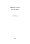
User
Manual
C2-20
ver 2,0
concens - ver 2.0
. - August 2010 - Check updates on www.concens.com or www.concens.eu
1
C2-20
User
Manual
C2-20
INTRODUCTION
C2-20 is a full H-bridge DC-motor
controller. It is designed to work with
con35 and con50 electrical in-line
actuators in applications where
some special functions are needed.
It is also possible to use this device
with actuators that gives pulses with
hall sensors. C2-20 has adjustable
acceleration and deceleration ramps,
which make the smooth starts and
stops possible .
Adjustable current limits in both
directions protects motor against
FEATURES
•
•
•
•
•
•
•
•
•
•
TECHNICAL DATA
overcurrent and it can also be used as
an endstop. This device has also two
adjustable speeds, whereas the 2nd is
used in the learning mode to count the
number of hall pulses in a full stroke of
the actuator. This enables an accurate
positioning of the actuator so it is
working as a servo.
Control input is a voltage. The stroke of
the actuator is controlled by sending a
DC voltage between 0-10,0 Volt to
the C2-20. Adjustments and settings:
Adjustments and parameter setting
like current limit value, ramp times,
speed-2 value and all other needed
parameters can be set with C2-PROG
interface unit, or USB cable with a
“dongle” connected to a PC or LAPTOP.
This enables the accurate copying of
settings and reliable operation of the
device in demanding environment. See
page 2 for more details.
Fast change of direction
Soft start-up, acceleration ramp
Settable current limit
Trip or continuous current limit
High efficiency
Dynamic braking
High momentary load capacity
Rail base fittable
Freewheel option
Two control modes
Supply voltage
9-35VDC
Actuator current continuous max 15A ( Ta<60°C )
Actuator current
max 20A (short time)
Current limit adj.
0.1-20A
Overheat limit
110°C
PWM frequency
2kHz
Hall input freq.
max 1khz
Input control logic:
“pos” ON=4-30V, OFF=0-1V or open
Control input impedances typ.
Motor and supply connectors:
Control connectors:
Dimensions
Dimensions in DIN-rail base
30kohm
2.5mm wires max
1mm wires max
42x72x25mm
45x80x45mm
CE-tested for industrial enviroment ( EMC )
Weight
75g
Operating temp ( Ta )
0-60°C
2
concens - ver 2.0
. - August 2010 - Check updates on www.concens.com or www.concens.eu
Recomended ripple lower than 20 %.
DC
First run the learning cycle and then do the
settings with serial interface unit “C2-PROG” or PC or LAPTOP
1/15 Speed - 35 - 100% <=> 35-100 ( 100 )
2/15 Learning speed - 35 - 100% <=> 35-100 ( 50 )
3/15 I-limit “out” 0,1 - 20,0A <=> 1-200 ( 20 )
4/15 I-limit “in” 0,1 - 20,0A <=> 1-200 ( 20 )
Notice! current limits are 1.5 times
higher during start ramp.
5/15 I-trip enable
6/15 I-trip delay 0 - 255ms <=> 0 - 255 ( 5 )
7/15 Load compensation 0 -255 <=> 0 - 255 ( 0 )
8/15 Pulse lost timeout 1 - 5s <=> 1 - 5 ( 2 )
9/15 Start value 0 - 50% <=> 0 - 50 ( 30 )
10/15 Hour/Start count reset 0 - 1, reset when set to 1
11/15 Brake area 0,0 - 20,0% <=> 0 - 200 (50)
12/15 Dead zone 0,0 - 10,0% <=> 0 - 100 (10)
13/15 Range scale in + 0,0 - 50,0% <=> 0 - 500 ( 7 )
14/15 Range scale out - 0,0 - 50,0% <=> 0 - 500 (70)
15/15 Start ramp 0,1 - 5s <=> 0 - 500 ( 100 )
C2-20
C2-20
WIRING AND SETTINGS FOR C
- Speed setting limits the maximum speed.
- Learning speed sets the learning cycle speed. ( pict. 2 )
- I-limits are individual for in and out directions
- I-trip enables the trip function, so that motor will be shut
down when the set I-lim is exceeded.
- I-trip
- Load compensation increases the torque at low speed.
Notice that over compensation will cause oscillation
and twiching of the motor.
- Pulse lost time-out stops motor after the set time without pulses.
- Brake area is proportional value of the full stroke.
In low speed application good value is near 1%, and in high
speed solution it can be near to 20% ( pict. 1 )
- Dead zone is steady area, suitable size of this zone depends
on the mechanical accuracy of the system, this value is also
a ratio of the full stroke (%) ( pict 1. )
- Start value is a voltage level for start (% of full),
this ensures that the motor gets an adequate voltage
to start properly, but notice that too high start level will
cause motor vibration (pict 1).
- Range scale adjustment is for scaling of the stroke, with this can
the scale be adjusted after learning. The in and out ends are
individually scaleable to get the suitable mechanical stroke for
set value from 0-5V ( pict. 3 )
- Hour/Start count reset makes possible to set the hour/start counter to zero
- Start ramp limits the acceleration speed when motor starts.
concens - ver 2.0
. - August 2010 - Check updates on www.concens.com or www.concens.eu
3
WIRING AND SETTINGS FOR C2-20 ver 2,0
PARAMETER SET
menu
select
save
+
TERMINALS:
PC
or
LAPTOP
-
+5,4V - voltage output, max 10mA
FAULT IN/OUT- pnp open collector max 100mA
can be connected to other C2-20 modules, thereby all modules connected
will stop if one module sends a FAULT signal. If wirelength is more than 1
meter, a 10kohm pull-up resistor connected to supply is recommended.
POS. SET - analog input 0-10V (0-5V if SW1 on 4 pole SW is OFF), Rin 30k
STOP/RESET - digital in. (>4V and max supplyvoltage) Rin 47k. Stops the
motor and resets any fault.
LEARNING - digital in. (>4V and max supplyvoltage) Rin 47k, starts “learning”.
POSITION OK - digital out 5 Volt through 1kohm when
wanted position is reached, and low during movement.
Note: if “Brake Zone” is very long, then POSITION OK signal can be difficult to reach, since the motor only gets very low power to reach within
the “dead zone”.
GND - signal gnd, same potential as terminal 4.
USB
GND
STOP/ RESET
POSITION IN 0-10V (0-5V)
LEARNING
9
+5,4 V
POSITION OK
8
FAULT IN/OUT
dongle
C2-USB
10 11 12 13 14
fault indication led
on
66
36
42
con35 cable
Black
Grey
1 Hall +
red
red
2 Hall A
yellow yellow
3 Hall B
green
green
4 Hall GND orange
blue
5 Actuator - black white/grey
6 Actuator + brown bwn/pur
off
72
1
2 3 4
DIPsw
Cables:
HEIGHT 25mm
con50 cable
Black
Grey
red
yellow
green
blue
blk/pur
bwn/or
red
yellow
green
blue
white/grey
bwn/pur
LED blinking signals
1
2 3
4
5
6
7
I-limit occurs = fast blinking
Overtemp = slow blinking
Pulse lost = short, mid, long, short mid long...
Over voltage = burst - pause etc.
+5.4V
+9 - 35V
+
picture 1 "positioning window"
GND (0V)
brake area
start ramp
dead zone
H
H
5
6
ACTUATOR
CONCENS 35/50
WITH HALL SENSOR.
M
start level
from old position
0V
in=0%
picture 2 "learning cycle"
10V
out=100%
4.
5.
2.
3.
setted
position
2 3 4
motor speed
1
to new position
picture 3 "range scaling"
range adj. in +20%
in=0%
in=20
range adj. out -20%
out=80%
out=100%
1.
6.
1.
1. start learning by giving an impulse to learn input (10)
2. motor starts to run “out” direction with learn speed
3. current limit stops the motor when mechanical end
is reached
4. motor starts to “in” direction and makes a full stroke.
During stroke the pulse counter measures the range.
5. motor reaches the mechanical end “in”, and current
limit stops the motor.
6. Device stores full range value and is ready for use
Specifications subject to change without prior notice. It is the responsibility
of the product user to determine the
suitability of concens as products for a
specific application.
4
2.
0V
10V (5V)
-20%
+20%
0V
10V (5V)
1. original learned range = mechanical full range
equals the signal range 0-10V
If range scale in = +20% and
range scale out = -20%.
now stroke of actuator is compressed to:
positioning set value 0V = 20% position
positioning set value 10V (5V) = 80% position
concens as
Øresundsvej 7
DK-6715 Esbjerg N
Denmark
Phone: +45 70 11 11 31
Fax: +45 76 10 50 10
Mail: [email protected]
Web: www.concens.com
concens - ver 2,0 - August 2010 - Check updates on www.concens.com or www.concens.eu
C2-20
C2-PROG