1
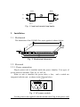
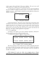
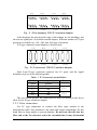
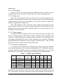
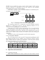
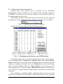
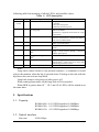
H10MO-480, H10MO-240, H10MO-120 Fiber Optic Modem User Manual Revision 1.0 2002/4 1. INTRODUCTION .......................................................................................................... 1 2. SYSTEM ARCHITECTURE ........................................................................................ 1 3. 4. 5. 2.1. BLOCK DIAGRAM ..................................................................................................... 1 2.2. FUNCTIONAL UNITS ................................................................................................. 2 2.3. PANEL ARRANGEMENT............................................................................................. 3 2.4. LOOP BACKS ............................................................................................................ 3 INSTALLATION ........................................................................................................... 4 3.1. MECHANICAL........................................................................................................... 4 3.2. ELECTRICAL ............................................................................................................ 4 3.2.1. Power connection............................................................................................... 4 3.2.2. E1 connection..................................................................................................... 5 3.2.3. Fiber connection ................................................................................................ 6 3.2.4. Grounding .......................................................................................................... 7 3.2.5. Order wire.......................................................................................................... 7 3.2.6. Alarm output ...................................................................................................... 7 3.2.7. Remote management .......................................................................................... 7 3.2.8. AUX data channels............................................................................................. 8 OPERATION AND MAINTENANCE......................................................................... 8 4.1. SWITCH-ON CHECKS................................................................................................. 8 4.2. SOFTWARE MONITOR AND CONTROL ...................................................................... 10 4.3. LED’S ................................................................................................................... 11 SPECIFICATIONS ...................................................................................................... 12 5.1. CAPACITY .............................................................................................................. 12 5.2. OPTICAL INTERFACE .............................................................................................. 12 5.3. E1 INTERFACE ........................................................................................................ 13 5.4. MANAGEMENT INTERFACE..................................................................................... 13 5.5. AUX DATA ............................................................................................................ 13 5.6. ALARM PORT ......................................................................................................... 13 5.7. POWER ................................................................................................................... 14 5.8. WORKING ENVIRONMENT ...................................................................................... 14 5.9. DIMENSION ............................................................................................................ 14 Note: Every effort is made to ensure that material printed in this manual is accurate until release. However we reserve the right to make improvements without prior notice. H10MO-480, H10MO-240, H10MO-120 Fiber Optic Modem User Manual 1. Introduction The H10MO-480 (-240, -120) fiber optic modem is designed to provide transmission of 16 (8,4) E1 channels over a fiber optic connection. Based on an internally developed ASIC, HMX3101, which integrates M12 and M23 multiplexers, E1 clock recovery units, digital PLLs, E1 cross connection, microcontroller interface, and other functional blocks in a single chip, the modem features compactness, light weight, low power consumption and high reliability. To ease the operation and maintenance effort, each H10MO-480 (-240、 -120) device has a built-in microcontroller unit, which allows remote supervision and control through a network management software running on a PC. For customers not equipped with the management software, a number of LEDs on the front panel are available for status and alarm indications. Local and remote loop back control can also be performed with panel dip switches. H10MO devices operate on 1.3µm lasers, with a typical transmission distance of 40 km over single mode optical fibers. For longer hops, 1.5µm laser sources may be selected. Apart from 16 (8, 4) E1 channels, the H10MO fiber optic modem also provides a RS232 and a RS485 asynchronous data channel, as well as an order wire telephone subsystem. Except power supply, all the functional blocks are integrated on a single PC board, which makes the modem compact and reliable. 220 V AC or -48 V DC power options are available by selecting an appropriate plug-in power unit. In the case of -48 V DC power supply, two plug-in units may be installed for redundancy. The device enclosure is a standard 19” wide 1U metal box, suitable for rack mounting, or as a desk top unit. 2. System Architecture 2.1. Block diagram The functional block diagram of H10MO-480 optical modem is given H10MO Fiber Optic Modem User Manual -1- below: HDB3x16 SV port RS232 RS485 E1 inerface uP unit E1x16 power in uP interface M13 MUX/DMUX power unit +5V E3 AUX data unit line unit O/E interface OW unit Fig. 1 Block diagram of H10MO-480 The functional block diagram for H10MO-240 and H10MO-120 systems are identical to that of H10MO-480, except the E1 channel capacity. 2.2. Functional Units The core of the H10MO modem is the M13 mux/dmux unit, which is realized with a single ASIC device, HMX3101. The device multiplexes 16 (8, 4) PDH E1 (2048kbps) tributary data streams into a single E3 (34368kbps) signal, and vice versa. E1 interface unit interfaces the HDB3 E1 signal to the HMX3101 ASIC, and performs impedance matching and line equalization functions. 75 Ω or 120Ω impedance can be selected. Built-in micro controller unit sets the operation mode of the HMX3101 ASIC, reads alarm status, calculates bit error rate, and communicates with the network management system for remote supervision. The functions of the order wire unit include telephone hand set interface, voice coding and decoding, signaling and ringing. AUX data unit provides RS232 and RS485 interfaces for two transparent, rate free asynchronous data channels. O/E interface unit transfers between electronic signal and optical signal for line transmission. Optical signal loss detection, clock and data recovery are also achieved in this unit. Line unit is used for clock translation, framing, AUX channel insertion, line coding, bit error detection functions. Power unit converts 220V AC or –48V DC supply into 5V internal power. -2- H10MO Fiber Optic Modem User Manual 2.3. Panel arrangement The front panel of H10MO-480 optical modem is as shown below: RLB DIP SWITCH 10-3 BER ALARM MASK DIP OW PHONE JACK CALL INDICATION SV INTERFACE RS232 LLB DIP SWITCH 10-6 BER E1LOS GROUP-A +5V POWER MAIN PROTECTION LOOP BACK REMOTE ALARM E3 LOS OF FRAME E1LOS GROUP-B -48V SWITCH E1LOS GROUP-C BELL OFF BUTTEN LOS OF OPTICAL SIGNAL E1LOS GROUP-D Fig. 2 Front panel As indicated, the 16 E1 ports provided by H10MO-480 are divided into 4 groups, labeled A, B, C, and D. Each group contains 4 E1 interface ports. An H10MO-240 modem provides only group A and B with 8 E1 ports, and an H10MO-120 modem provides only group A with 4 E1 ports. The rear panel of H10MO modem is shown below: Protection ground Output fiber connector power chamber Alarm out and bell-off SV RS485 port E1 interface -48 power in AUX RS232 port Input fiber connector AUX RS485 port Bus termination for SV RS485 Fig. 3 Rear panel 2.4. Loop backs The H10MO modems support panel dip switch control of loop backs to allow for installation and maintenance checks. Remote loop back (RLB) and local loop back (LLB) control results in loop backs as shown below: H10MO Fiber Optic Modem User Manual -3- LLB RLB E1 E1 local unit remote unit Fig. 4 local and remote loop backs 3. Installation 3.1. Mechanical The dimension of the H10MO fiber optic modem is shown below: 435mm 244mm 44.45mm 31.8mm 465mm 482mm Fig. 5 Mechanical dimension 3.2. Electrical 3.2.1. Power connection Plug-in power unit is installed inside the power chamber. Two types of power units are available, 220V ac, or –48V dc. When ac unit is installed, the power inlet, a fuse, and a switch are integrated with the unit , as shown in the diagram below. fuse switch N L E inlet Fig. 6 AC power module Use the power cord supplied with the modem unit. Plug in the power cord -4- H10MO Fiber Optic Modem User Manual to the ac power inlet at the back of the power chamber. Be sure to use a wall outlet with correct voltage and a secure earth connection. If –48V dc power is selected, 1 or 2 DC/DC converter cards are installed in the power chamber according to purchase options. A cover plate is fixed on the chamber by screws. –48V dc power connector is on the right side of the power chamber as shown below. PWR CHAMBER PWRIN release lever V GND Fig. 7 DC power connector Connect the modem to –48V power source using a pair of wires about 1mm in diameter to the power-in connector. Remove about 10mm of the protective insulator from the wire end. Prepare the wire end with solder. Push inward the yellow release lever on top of the connector with a screw driver, plug the prepared wire end well into the hole, then release the push. Note that the left hole is for –48 supply, and the right hole is for ground. 3.2.2. E1 connection According to the number of E1 ports and their impedance, different E1 interface adapters are used on different modem units. A 75Ωcoaxial E1 interface adapter is shown below: A-IN B-IN C-IN D-IN 1 2 3 4 1 2 3 4 1 2 3 4 1 2 3 4 1 2 3 4 1 2 3 4 1 2 3 4 1 2 3 4 A-OUT B-OUT C-OUT D-OUT Fig. 8 Coaxial 75Ω E1 interface adapter The outer conductors of the output jacks are earthed, while the input jacks are floating. H10MO-480 modems contain all the jacks, H10MO-240 modems have group A and group B jacks, while only group A jacks are available on H10MO-120 modems. 120Ω balanced E1 ports use either wire wrapping pins or D-type connectors for E1 signal connection. A wire wrapping adapter is shown below: H10MO Fiber Optic Modem User Manual -5- A-IN B-IN C-IN D-IN 1 2 3 4 1 2 3 4 1 2 3 4 1 2 3 4 1 2 3 4 A-OUT 1 2 3 4 1 2 3 4 1 2 3 4 B-OUT C-OUT D-OUT Fig. 9 Wire wrapping 120Ω E1 interface adapter In the diagram, the pins near the edge of the adapter are for shielding, and the rest are signal pins. As with the coaxial adapter, different number of E1 port groups are available for -120, -240, and -480 type of modems. A D-type connector based adapter is shown below: A-IN B-IN C-IN D-IN A-OUT B-OUT C-OUT D-OUT Fig. 10 D-connector 120Ω E1 interface adapter Each 9-pin D-type connector connects two E1 ports, and the signal definition is given in the following table: Table 1 E1 connector pin definition Pin No. Signal Port 1,shell ground 2,6 in E1-1 3,7 out 4,8 in E1-2 5,9 out The user should prepare the connectorized cables according to the above table for the D-type connector adapter. 3.2.3. Fiber connection Use FC type connectors to connect the fiber optic modem to the transmission cable. Pay attention to the input and output relationship. Do not bend fiber to sharp angles to prevent damage. Do not look directly into the fiber end or the Tx connector socket for extended time, it may be harmful -6- H10MO Fiber Optic Modem User Manual to the eyes. 3.2.4. Grounding Fasten a wire to the protection ground connector screw, which is on the rightmost side of the rear panel. Connect the wire to the shielding ground. 3.2.5. Order wire The order wire telephone jack is on the left side of the front panel. Any standard 2-wire telephone set with a RJ11 connector may be used. Note that the ringing current is not sent to the telephone set. Instead, a buzzer is inside the modem to signal the incoming call. The OW telephone works in hot line mode. When one end picks up, the other end rings. There is a visual incoming call indicator LED to the left of the phone jack in order to identify the ringing modem, in case more than one are installed in close proximity. 3.2.6. Alarm output An alarm and bell-off signal socket is at the right side of the rear panel. The left pin is alarm output, which floats when the modem works normally, and connects to shielding ground to indicate alarm conditions. The right pin is for terminating the alarm bell sound. It floats normally, but connects to shielding ground when Bell-off button on the front panel is pushed down. This is useful only if the system is used with a rack-top alarm unit. 3.2.7. Remote management For customers who purchased the management software package, H10MO fiber optical modems can be remotely managed by a PC. With each software package, a RS232 to RS485 converter is supplied. Plug the converter to a COM port on the PC, and make a RS485 cable according to the following table: Table 2: RS485 cable definition # PC 1 2 3 connector type DB-9-F DB-9-F DB-9-F DB-9-F Length (m) NA (e.g. 10) (e.g. 0.2) (e.g. 0.2) TxP pin 3 2 2 2 TxN pin 4 3 3 3 RxP pin 1 4 4 4 RxN shell pin 2 √ 5 √ 5 √ 5 √ Connectors are connected together in parallel by a 5-wire cable. Pin numbers for each connector listed in the same column are attached to the same wire. The number of entries (connectors) in the table depends on the number of H10MO Fiber Optic Modem User Manual -7- H10MO devices installed for remote control, and the length of cable sections between connectors is determined by the user, based on the positional relationship between the PC and the modems. In the Table 2 example, 3 pairs of H10MO modems are controlled by a PC, as depicted in the following figure. C P RS232/RS485 converter 1 2 3 H10MO H10MO H10MO PC local 1 remote H10MO 2 H10MO 3 H10MO Fig. 11 Remote control of H10MO modem pairs The connector labeled PC is connected to the RS232/RS485 converter attached to a COM port on the PC, and the connectors labeled 1,2,3 are connected to the SV RS485 ports on each modem. To the right of SV RS485 socket on each modem, there is a termination dip switch. If the modem is at the end of the RS485 cable, e.g. No.3 in Fig. 11, the switch dips should be pressed down, otherwise, they should be lift up. Do not confuse the SV RS485 socket with the AUX RS485 socket when making the connection. The RS232 socket on the front panel is used for local connection. 3.2.8. AUX data channels The AUX data ports are used to provide 2 transparent asynchronous serial data channels with line rate up to 100kbps. One port interface is RS232, and the other , RS485. Both use 9-pin D-type connectors on the rear panel, and the pin-signal relationship is given in the table below. Table 3: AUX data channel interface connector definition PIN No. RS232 RS485 2 Rx TxP 3 Tx TxN 4 RxP 5 GND RxN shell shield shield 4. Operation and maintenance 4.1. Switch-on checks When all the connections are down, switch on the unit. Observe all the -8- H10MO Fiber Optic Modem User Manual alarm LED’s for any possible installation errors. Check the output optical power using an optical power meter. The reading should be within specification. Measure the optical power at the receiver end. Make sure that the power level is between the maximum allowable input power and sensitivity given in the specification. It is preferred to leave a margin of few dB’s for stable operation. If all the alarm LED’s are correct (refer to section 4.3 for description of the alarm LED’s), try to contact the other end using the order wire telephone. Successful conversation means that the modem is working normally. If software management is required, each modem pair should be given a unique network address. In addition, the local unit should be set to a node address of 0, and the remote be set to 1. The address setting is down through SV RS232 port, and will be kept in non-volatile memory. If software management is not used, address setting is not required. Press down the local loop back (LLB) dip switch at the front panel, the yellow LB LED lights up. Measure any E1 channel using a bit error rate tester, no error should present. Cancel the LLB. If the remote end is already operational, press down the remote loop back (RLB) dip, measure any E1 channel, no error should be found. Cancel the RLB, and the modem pair should operate normally. Connect all the E1 signals to the appropriate E1 ports, check the operation of the services provided by these E1 channels. When all the service are setup correctly, and there are spare E1’s available, those unconnected E1’s will result in “loss of E1 signal” alarms, which will be indicated by appropriate LED’s, and the system alarm port will report this alarm condition. Since these are not real defects, they can be suppressed by setting an alarm mask by press down the alarm mask control dip switch on the front panel (ALM-MSK). Thus, the spare E1’s will not lit E1 LOS LED lights, nor there will be system alarm output. Only newly appeared defects affecting normal operation will then cause alarms. After alarm mask setting, if the dip switch is lifted up, all the unconnected E1’s will still cause their respective LOS LED’s to light up, so that the operator can observe which E1 ports are available, but system alarm output remains masked. The alarm mask is stored in non-volatile memory, and will remain valid even after power off. Note that the alarm mask cannot be unset. If operation condition changes, for example, a spare E1 is put into service, then one must re-apply the mask setting to reflect the change. Otherwise, the loss of that added E1 signal will not cause alarm. H10MO Fiber Optic Modem User Manual -9- 4.2. Software monitor and control H10MO fiber optic modems can be managed by the H7GMSW management software, running on a PC platform. See operation manual of H7GMSW for operation of the software package. Only the details specific to H10MO modems are given here. The H10MO modem is represented by the following icon in the graphical management window. When any alarm condition is present, the icon flashes. Fig. 12 Screen icon of H10MO modem Double click the icon brings out the following window. Status Setting box Response Control button Fig. 13 Management window for an H10MO modem Monitoring and control is performed through this window. In the window, there are status circles, setting boxes, response boxes, and control buttons. Status circle indicates a specific status, including alarm and current loop back setting, by showing a dot inside the circle. Setting box is used to select loop back of specific channel and type. Control button is for carrying out the selected loop back, or close the window. Response box indicates, by showing a cross in the box, response from the modem under control after a control button is pressed. For example, if a solid dot appears within the status circle at the cross section of row 2MD4 and LLB column, it means that the No.4 E1 in E1 group D -10- H10MO Fiber Optic Modem User Manual is set to local loop back. Note that RLB and LLB here refer to a specific port / line, not the location of a modem unit in a local or remote site, as depicted below: equipment line equipment line remote end loop back RLB local end loop back LLB Fig. 14 Loop back definition To set a specific port loop back, move the mouse cursor to the appropriate setting box, click to bring up a check sign, and click the “E1 loop back control” button. Any number of E1 loop backs can be set with a single control. To remove a loop back, click the setting box to remove the check sign, and click the “E1 loop back control” button again. The E3 local loop back is controlled by “E3 loop back control” button. Note that the E3 loop back can only be set at the local modem, but not to the remote, otherwise the loop back will block the data communication channel, and there will be no way to remove the loop back. Following monitoring and control can be performed on H10MO modems through the management software: Los of signal at any E1 port Alarm indication (AIS) at any E1 port Loop back status and types (LLB or RLB) of each E1 port ,control of loopbacks Los of incoming optical signal Bit error rate over 10 −3 (1E-3), or between 10 −3 and 10 −6 (1E-6) E3 loss of frame E3 AIS E3 loop back (34M LLB)status and control 5V power module failure (if protection is available) 4.3. LED’s There are reach LED’s on the front panel of the H10MO modem. The H10MO Fiber Optic Modem User Manual -11- following table lists meaning of all the LED’s and possible causes . Table 4: LED description LED +5V(A) +5V(B) E1LOS OLOS E3LOF RA 1E-3 1E-6 color Meaning when lit green +5V output OK Possible cause Off: power module failure / power module not installed +5V(A) the main power +5V(B) the protection power red E1 signal loss On: spare E1 /cable defect / up stream failure / 16 in 4 groups input circuit failure Off when E1 is applied: alarm mask set / input circuit failure red Los of optical signal On: remote switched off / broken fiber/ excessive connection loss / remote laser failure / local receive module failure red E3 loss of frame On: excessive transmission error / remote unit failure / local unit failure yellow Remote alarm On: remote OLOS / remote 1E-3 BER / remote E3LOF red Bit error rate greater than On: excessive connection loss / remote laser ageing / local receiver ageing / excessive 10 −3 incident optical power yellow Bit error rate greater than Same as above 10 −6 LB CALL yellow Loop back on On: LLB dip pressed down / remote RLB dip pressed down / some ports set to loop back mode through software control green Remote OW phone off-hook Note: Loop back control switch is not position sensitive, a command is issued only at the moment when the dip is pressed down. Turning on the unit with the dip down does not activate loop back. Loop back status is not preserved after power off. When setting alarm mask, all the loop back will be canceled. When BER is greater than 10−2 , 1E-3 and 1E-6 LED’s will be turned on at the same time. 5. Specifications 5.1. Capacity H10MO-480: 16 E1 PDH signals at 2.048Mbps H10MO-240: 8 E1 PDH signals at 2.048Mbps H10MO-120: 4 E1 PDH signals at 2.048Mbps 5.2. Optical interface Line rate: -12- 41241.6kbps H10MO Fiber Optic Modem User Manual Line code: Wavelength: Scrambled NRZ 1.3μm(typical) 1.5μm(optional) Optical source: LD Optical receiver: PIN-FET Connector: FC Optical budget: ≥22dB (typical) 29dB...35dB (optional) Maximum input power: -3dBm 5.3. E1 interface Bit rate: Line code: Impedance: 2048kbps±50ppm HDB3 75Ω (unbalanced) or 120Ω (balanced) 5.4. Management interface Main interface: RS485, 2400 bps, TABS protocol Data bits: 8, Stop bits: 1, Parity: odd 9 pin D type connector Note book interface: RS232, 2400 bps, TABS protocol Data bits: 8, Stop bits: 1, Parity: odd 9 pin D type connector 5.5. AUX data RS232: 3 line (Tx,Rx,GND) asynchronous 0-100 kbps,9 pin D type connector RS485 4-line (TxP,TxN,RxP,RxN) asynchronous 0-100 kbps,9 pin D type connector 5.6. Alarm port System alarm out: Bell off: Ground when alarm, float otherwise Ground when activated, float otherwise H10MO Fiber Optic Modem User Manual -13- 5.7. Power DC type: AC type: Power consumption: ±48V(-36V to -72V or 36V to 72V) 220V(165V~265V) ≤10W 5.8. Working environment Temperature: Humidity: 0 ~45°C ≤90% non condensing 5.9. Dimension Width: Height: Deep: -14- 435mm 45mm 244mm H10MO Fiber Optic Modem User Manual