1
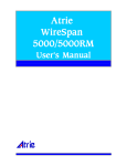
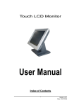
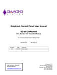
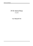
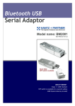
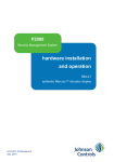
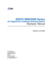
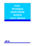
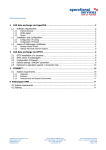
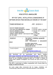
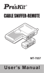
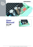
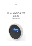
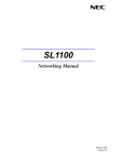
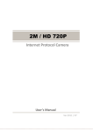
Atrie WireSpan 4000 IDSL MODEM User's Manual WireSpan 4000 IDSL User's Manual Version 1.3 TABLE OF CONTENT 1. Introduction............................................................................................3 2. Features and Specification................................................................3 3. Installation ......................................................................................4 3.1 WireSpsan 4000 IDSL wiring........................................................................................4 3.2 WireSpsan 4000 IDSL Stand-Alone Front Panel Operation................................6 4. Command Menu Tree of WireSpan 4000 IDSL ................7 5. Configure the WireSpan 4000 IDSL .................................................8 5.1 Show Setup.........................................................................................................................8 5.2 Show I/F Signal(remote device only).........................................................................8 5.3 Chang Setup.......................................................................................................................9 5.3.1 Data Rate.....................................................................................................................9 5.3.2 Control Signal..........................................................................................9 5.3.3 Timer.........................................................................................................................9 5.3.4 Clock Source....................................................................................................9 5.3.5 Error Seconds Threshold....................................................................................9 5.3.6 Remote Configuration.............................................................................................10 5.3.7 Follow Profile......................................... .................................................10 5.3.8 Set Unit Default........................................................................................10 5.3.9 Voice Control(Only changeable by Stand-Alone Unit)......................10 5.4 Reset Device......................................................................................................10 5.5 Save Setup.........................................................................................................10 6. Diagnostic of the WireSpan 4000 IDSL .........................................11 6.1 LL Test: Local Loopback Test.....................................................................................11 6.2 RL Test: Remote Loopback Test.................................................................................11 6.3 RAL Test: Remote Anolog Loopback Test..................................................................11 6.4 DL+511 Test: Digital Loopback with 511 Test Pattern...........................................12 6.5 LL+511 Test: Local Loopback with 511 Test Pattern..............................................12 6.6 RL+511 Test: Rocal Loopback with 511 Test Pattern.............................................12 6.7 RAL+511 Test: Remote Loopback with 511 Test Pattern.......................................12 6.8 DL Test: Digital Loopback .............................................................................................13 6.9 511 Test Pattern..................................................................................................................13 6.10 Test Time............................................................................................................................13 7. SetUp Copy Configuartion (Only for Rack Mount).....................13 1. Introduction The WireSpan 4000 IDSL uses 2B1Q line coding to allow reliable and cost-effective full-duplex transmission at speed up to 128 Kbps and Voice port over one pair of existing copper subscriber lines. It provides data and voice services simultaneously. Adaptive equalization and echo cancellation ensures consistent performance, even over poor quality lines. It has a comprehensive V.54 loop test function allowing easy optimal speed calibration and troubleshooting without the need for a cable tester. The stand-Alone unit is easy to use and configure through a menu-driven LCD control panel. The Rack unit is easy to use and configure through DIP switch and push button. The WireSpan 4000 IDSL satisfies the requirements of a variety of high-speed data communication applications. 2. Features and Specification WireSpan 4000 IDSL Stand-Alone Unit z Menu-driven 2 x 16 LCD control panel for easy configuration and diagnostics. z Configuration and set-up verification of remote unit. z Comprehensive error reporting with external alarm trigger. z Built-in 511 pattern generation/detection and V.54 remote digital loopback. z Data Rate: Synchronous : 4.8k, 9.6k, 19.2k, 38.4k, 48k, 56k, 64k, 72k, 112k, 128 kbps. Asynchronous : 4.8k, 9.6k, 19.2k, 38.4kbps z Line Operation: Full duplex over 2-wire subscriber line up to 5.5km (18 kft @ 0.4mm cable), complying to ANSI T1.601, ITU-T G.961 specification. z Transmission: Synchronous, 2B1Q line coding with adaptive echo-cancellation and equalization. z Transmit Level: 13.7 dBm z Line Impedance: 135 ohms balance z Voice and data service simultaneously. z Provide FXO interface at Central side and FXS interface at remote side.(Option) z Voice interface meet ITU-T G.712 transmission requirements z Wide choice of DTE port, V.24, V.35, G.703 and X.21 z Programmable flow control: CTS, RTS and Anti-Streaming delay time. WireSpan 4000 IDSL Rack Unit z Data Rate: Synchronous:4.8k,9.6k,19.2k,38.4k,56k,64k,72k,112k,128kbps. Asynchronous:4.8kbps,9.6kbps,19.2kbps,38.4kbps. z Line Operation:Full duplex over 2-wrie subscriber line up to 5.5km(26AWG cable) z Support the V.110 rate adaption. z Line Rate : 160 Kbps z Base on ISDN U-interface. z Fully Compliant with ANSI T1.601-1992 specification. z Transmit Level : 13.7 dBm. z Line Impedance : 135 Ohms. z Line Interface:RJ-45/Teminal Block. z Line interface circuitry protects against lightning and power surges. WireSpan 4000 IDSL User’s Manual 3 z DTE Interface:V.35,RS-232D/V.28,G.703. z Diagnostics Testing : LL, RL, DL, DTE Loopback, BERT build in 511. z Input Voltage:AC90~260 Volts/47~63Hz,or -36 to –72 Vdc Single or Daul power(option). z Power Consumption : 5W(Max.)/Per z 10 LEDs Indicators : SYN,TST,TD,RD,CD,RTS,CTS,DTR,DSR,PWR. z Rack Size :1. 16 port (16 pieces)per Rack with Power Module in 19’’ Rack Shelf./482mm(L)×8.3’’/210mm(W)×175mm(H) z Operating : 1.Temperature:0 to 45ºC (Operating); z 2.Relative Humidity : 0 to 80% non-condensing. z Clock Source Select : Internal, External, Loop. Management : Lacal Configuration, Remote Configuration., SNMP, Console(Option) 3. Installation 3.1 WireSpan 4000 IDSL wiring Once you unpacking the WireSpan 4000 IDSL unit, the following accessories are included. AC Power Cord Connection box RJ-11 Cable Voice Module 1 pcs(Stand-Alone Only) 1 pcs(Stand-Alone Only) 1 pcs 1 pcs (option for Stand-Alone) Follows the steps and figure3.1 to install the Stand-Alone unit. follows the steps and figure3.2 to install the Rack unit. The pin definition of the following each connector, Please refer to section 3 descriptions. Step 1: Install DTE cable to the external equipment properly. WireSpan 4000 IDSL provides V.35 , V.24 , and G.703 data ports. Step 2: Install RJ-11(Stand-Alone)/RJ-45(Rack-Unit) cable to the other end of WireSpan 4000 IDSL. Step 3 (Only for Stand-Alone) : Install Voice Module (option) from rear panel and push to the seat properly. Please unscrew the voice module cover firstly. Make sure the FXO module is installed in the Central Site (local carrier company or switches), the FXS is in the remote site (to the telephone set or PBX). Step 4: Make sure the power switch is turned OFF and install AC power cord (auto-range from AC 90V to 260V) with Stand-Alone or AC/DC power card(-36Vdc to –72Vdc) in Rack-Unit . Step 5: Turn ON power switch and enjoy it. 4 ON OF F AC DTE Port (V.35,V.24, G.703,X.21) DT E LIN E To AC Power 90 ~ 260 V To DTE To Other IDSL Figure 3.1- Wiring WireSpan 4000(V.35) Stand-Alone Unit CH15 CH14 CH13 CH12 CH11 CH13 CH15 CH10 CH11 CH0 87654321 ON 10 BASE T I II 1LA L1A 2LB L1B 3PA L2A 4PB L2B 5TXA 6TXB 7RXA 8RXB OFF III FG DC-48VGND CONSOLE CH0 CH11 CH12 CH13 CH14 CH15 AC POWER Figrue 3.2 WireSpan 4000 Rack Back pane CH 0~15 DB25 (Female) DTE Connecter.You can to use Standard DB25-DB25 or DB25-M34 Change-Cable(Only ATRIE defined) to connect V.24/V.35 Interface FG/SG F ground/Signal ground DC-48V GND - 48 Vdc input AC POWER 90~260 Vac input L1A/L1B(III) Line interface to Others WireSpan 4000 (Non-polarity) G703TxA/B Only for WireSpan 4000 Rack-Unit is G.703 Interface Co-direction unit . “Attention” The RJ45/Terminal Block is to be linked together. It’s suggest to use 8P/2C RJ45 cable to connect other WireSpan 4000 When use G.703 interface to connect other DCE Device. 10 BASE T SNMP Ethernet connecter CONSOLE Reserve function WireSpan 4000 IDSL User’s Manual 5 Dedicated V.35 Change-Cable Definition (Only WireSpan 4000 IDSL Rack System by used) 3.2 WireSpan 4000 IDSL Stand-Alone Front Panel Operation TD RD SYN TST ALM PWR IDSL Access Unit ENTER DTR DSR DCD RTS EXIT CTS 9 2 x 16 characters LCD Display the Command Menu of Modem Status, Alarm messages and Configuration. 9 Push buttons: ◄ ► Scroll through available options ENTER Choose current option EXIT Go back to previous menu 9 LED displays: PWR Lights when power is ON. SYN Sync indicators. Blinks until DSL pair is synchronized. TST Loop Test indicator ALM Error detect. RD Receive data indicator TD Transmit data indicator Voice Port Status indicator: ON/ Off-Hook, OFF/ On-Hook or No voice port, Flashing/Ring 6 LED displays: SYN TST TD RD CD RTS CTS DTR DSR PWR Sync nicators. Blinks until DSL pair issynchronized. Loop Test indicator Transmit data indicator Receive data indicator Data Carrier Detect Request To Send Clear To Send Data Terminal Ready Data Set Ready Lights when power is ON. 4. Command Menu Tree of WireSpan 4000 IDSL Local & Remote Configuration Password Control Enable , Disable Enter Password Data Rate Sync Mode, Async Mode Flow Control Signal CTS, DSR, DCD, Anti-Streaming Timer RTSÆCTS On Delay, DCD Off Delay, Anti-Streaming Clock Source Internal, External, Received Voice Control Select A/U Law, FXO/FXS control Reset Default Setting Save Changes(for local configure only ) Send Configure ( for remote configure only ) View Local & Remote Configuration Data Rate WireSpan 4000 IDSL User’s Manual 7 Port Type Clock Timer Test Time Flow Control Signal(for remote configure only) Diagnostics LL Test RL Test RAL Test LL + 511 Test RL + 511 Test RAL + 511 Test DL + 511 Test DL Test 511 Test Pattern Test Time Test Time = infinite Test Time = 5 min. to 255 min. 5. Configure the WireSpan 4000 IDSL The Modem has been configured at the factory with the following default settings. PARAMETERS DEFAULT Data rate 64 kbps CTS Always On DSR Always On DCD Always On Anti-Streaming Off RTS to CTS Delay 50 ms DCD Off Delay 0 ms Anti-Streaming timer 30 seconds Clock Source Internal Error Seconds Threshold 60 seconds Remote Configuration Enabled 5.1 Show Setup This screen can be viewed from the current Modem Setup with the following parameters. Data Rate, Port Type, Clock Source, Anti-Stream On/Off, Anti-Stream Time, Test Time, RTS Æ CTS Delay Time, DCD Off Delay Time, CTS/DSR/DCD On and Off status, Voice Port Status 5.2 Show I/F Signal (remote device only) If the remote modem are being configured, this command will show the existing interface control signal status, CTS, RTS, DCD, DSR and DTR. The ✶ indicate signal is ON. CTS ✶ RTS ✶ DCD ✶ DSR ✶ DTR ✶ OK 8 Or Rack-Unit CTS,RTS,DCD,DSR,DTR LEDs is ON 5.3 Change Setup 5.3.1 Data Rate Sync and Async data rate are provided : Synchronous : 4.8k, 9.6k, 19.2k, 38.4k, 48k, 56k, 64k, 72k, 112k, 128 kbps. Asynchronous : 4.8k, 9.6k, 19.2k, 38.4kbps 5.3.2 Control Signal a) CTS: Follow remote DCD, Follow local RTS and Always ON. b) DSR: Follow remote DTR, Follow local DTR and Always ON. c) DCD: Follow remote RTS, Always ON or Follow By Sync (Once the DSL line is synchronized, the DCD is turned ON automatically). d) Anti-Streaming: Switch ON, Switch OFF Anti-Streaming is a method of preventing domination by any one modem during half-duplex operation by forcing CTS off if RTS remains on over a given amount of time (Anti-Streaming Time). 5.3.3 Timer a) RTS Æ CTS ON Delay Time: from 0 to 255ms (increment by 5 ms) This feature provides a given delayed time to turn CTS on after RTS is ON. b) DCD OFF Delay Time: from 0 to 255ms (increment by 5 ms) DCD ON signal continues for a given period of time after the loss of line signal (DCD is OFF). c) Anti-Streaming Time: from 0 to 255 seconds (increment by 5 seconds) 5.3.4 Clock Source a) Internal: Central Site Modem select internal free-running clock as a master clock. b) External: Central Site Modem follow external DTE clock as a master clock. c) Received: Remote Site Modem extracted clock from received line signal. 5.3.5 Error Seconds Threshold The WireSpan 4000 IDSL samples the number of CRC error per 60, 300 and 900 seconds simultaneously, known as Error Seconds. Each of these Error Seconds has a minimum and maximum level. When the Error Seconds goes over the maximum threshold, the modem triggers the alarm. When the Error Seconds falls below the minimum level it will automatically cut-off the alarm. a) ES60s : Provide minimum (00) to maximum (060) error seconds setting per 60 seconds period. b) ES300s : Provide minimum (00) to maximum (300) error seconds setting per 300 seconds period. c) ES900s : Provide minimum (00) to maximum (300) error seconds setting per 900 seconds period. WireSpan 4000 IDSL User’s Manual 9 5.3.6 Remote Configuration In order to prevent unauthorized person to change configuration, WireSpan 4000 IDSL provides a facility to enable or disable configuration from remote modem. a) Unit Enable : Enable configuration to the remote modem b) Unit Disable : Disable configuration to the remote modem 5.3.7 Follow Profile This feature allows the current modem Setup to be a Data Port Profile. The LCD will display “Set Data Port as Profile”. 5.3.8 Set Unit Default This command setup the current modem with predefined default parameters. Total is 6 default parameters option. List below table: Default Number Clock Source Data rate 1. Internal 64K 2. Internal 128K 3. External 64K 4. External 128K 5. Received 64K 6. Received 128K *Control Signal is non-changed(Factory default value) 5.3.9 Voice Control (Only changeable by Stand-Alone Unit) The WireSpan 4000 IDSL provides FXO or FXS voice port on the modem card. If the voice port is installed and enabled, the data rate is restricted under 64 kbps data rate automatically. The FXO port is connected to the Central Office (CO or PSTN, Switches), the FXS is connected to the regular telephone set or private PBX/Key Telephone system. WireSpan 4000 IDSL detect FXO/FXS voice module automatically and can be enabled or disabled by CM unit. The voice is transmitted with 64 kbps PCM code, A or u-Law. a) FXO/FXS Enable/Disable : Enable or Disable voice module. b) A/u-Law : Configure voice with A-Law or u-Law 64 kbps PCM code. 5.4 Reset Device Select this command will reset the current Modem module. The Modem module re-start according to the pre-defined setting. 5.5 Save Setup After finished configuration, tthe following SAVE information. NOTE: All Change Setup have to be saved in order to save to non-volatile RAM. After reset or power off the modem, the Change setup parameters can be resumed. 10 6. Diagnostic of WireSpan 4000 IDSL The WireSpan 4000 IDSL has 8 sets of V.54 loop tests. It also has an internal 511 Bit Error Rate Test (BERT) pattern generator. These loop tests allow you to check the reliability of the installation, to calibrate for optimum performance or, in case of problems, to do troubleshooting. The different loop tests are described in the following table. To activate these functions, please follow the following Command Menu Tree. Local Device or Remote Device Æ Device Management Æ Diagnostic The test interval of each test is defined by Test Time at the following command. If the test need to be stopped immediately, press ► and ◄ key and then OK key to stop the test command. The following V.54 looptest with 511 test pattern will indicate the Error Bits (show ErrBits = …… )on the LCD display immediately. Press ► and ◄ key and then OK key to stop the test command. 6.1 LL Test : Local Loopback Test Test from the local DTE up to the line interface of the local unit. DTE TD RD Remote Modem Local Modem DTE Line Interface Digital Interface 6.2 RL Test : Remote Loopback Test Test from the local DTE up to the Digital interface of the Remote unit. The WireSpan 4000 IDSL Pair has to be in Sync mode. DTE TD RD Remote Modem Local Modem DTE Line Interface Digital Interface 6.3 RAL Test : Remote Analog Loopback Test Test from the local DTE up to the line interface of the Remote unit. The WireSpan 4000 IDSL Pair has to be in Sync mode. DTE TD RD Remote Modem Local Modem DTE Line Interface Digital Interface WireSpan 4000 IDSL User’s Manual 11 6.4 DL+511 Test : Digital Loopback with 511 Test Pattern Testing using 511 BERT pattern generated from the remote unit up to the digital interface of the local unit. The WireSpan 4000 IDSL Pair has to be in Sync mode DTE Remote Modem Local Modem DTE 511 Gen. Line Interface Digital Interface 6.5 LL+511 Test : Local Loopback with 511 Test Pattern Test using 511 BERT pattern generated from the local unit up to the line interface of the local unit. DTE Remote Modem Local Modem DTE 511 Gen. Line Interface Digital Interface 6.6 RL+511 Test : Remote Loopback with 511 Test Pattern Test using 511 BERT pattern generated from the local unit up to the digital interface of the remote unit.The WireSpan 4000 IDSL Pair has to be in Sync mode. DTE Remote Modem Local Modem DTE 511 Gen. Line Interface Digital Interface 6.7 RAL+511 Test : Remote Analog Loopback with 511 Test Pattern Test using 511 BERT pattern generated from the local unit up to the digital interface of the remote unit. The WireSpan 4000 IDSL Pair has to be in Sync mode. DTE Local Modem Remote Modem DTE 511 Gen. Line Interface Digital Interface 12 6.8 DL Test : Digital Loopback Testing using 511 BERT pattern generated from the remote unit up to the digital interface of the local unit. The WireSpan 4000 IDSL Pair has to be in Sync mode DTE Remote Modem Local Modem DTE Line Interface Digital Interface 6.9 511 Test Pattern The WireSpan 4000 IDSL generates a 511 test pattern between both local and remote sides to verify the data transmission are working well. To perform this feature, both sides have to enter “511 Test Pattern” mode. Press ◄ and ► key on the local front panel under this mode to send an error bit to remote modem. Press one key to generate one error bit. TP_511 running ErrBits = 0 Press ◄ and ► key on the local Modem. 6.10 TP_511 running ErrBits = 2 Generate error bits on the remote Modem. Test Time a) Time = infinite : Setup test time infinite until manual stop. b) Time = 005 min to 255 min : Setup test time duration from 5 minutes up to 255 minutes. (increment by 5 minutes) 7. Setup Copy Configuration(Only for Rack Mount) In order to provide a faster method for setting up several modems. You can use copy configuration menu and choose one of Rack mount to copy setup to another rack mount. This function is effective when ROM version on Rack Mount is the same. WireSpan 4000 IDSL User’s Manual 13