1
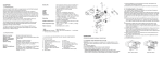
B
int A
yright
© Cop
Cop
ent.
t. ©
nsen
cons
n
writte
n co
out
r with
anne
er w
in an
ed
or us
any
ed in
party
or us
third
party
d to
any
third
lose
disc
d
ed,
oduc
lose
disc
pr
be re
ed,
duc
t no
t
repro
mus
t be
and
t AB
s (g)
poin
Mas
e
Aim
Scal
1,6 μm
ess Ra
date
ughn .
ies
Rev.
ce ro 1302
appl
Surfa. to ISO
ing
2
llow
acc
no.
e fo
dii 0,
ECM
ed th
llet ra
at
Fi
st
e
ent.
rwis
no. aterial
n.
rsion
atm 68-m.
g
othe
ke
ve
in
tre
M
ss
w
,
bro
ce
PDM
Dra
O 27
Unle
ges
0
surfa . to IS
rp ed
fter
cc
Sha
ns a
es a
hod
ensio leranc
. met
to
Dim
Proj
eral
Gen
EPT
vel
ner
1:1
d by
n
atio
Aim
t
poin
start
th
ts is
p
en
mbly
asse
cont
C
CON
le
omin
Den
Desig
d its
t an
ase
Rele
E
oved
Appr
0
Date
x
9xxx
0
Date
by
A4r2
wing
follo
the
ated
ise st
ent.
herw
on
atm
-m.
en.
versi
ss ot
ce tre O 2768
s brok
PDM
Unle
0
edge ter surfa c. to IS
p
Shar sions af
es ac
en
ranc
Dim al tole
er
Gen
ase
Rele
CON
ion
minat
t st
poin
Aim
Deno
mbly
sse
art a
T
CEP
l
leve
ing
Draw
te
da
Rev.
no.
bild
pro-
t
Shee
1/ 1 n
io
Revis
0
A4r2
Aimpoint AB
Jägershillgatan 15
SE- 213 75 Malmö, Sweden
Phone +46 (0)40 671 50 20
Fax +46 (0)40 21 92 38
e-mail: [email protected]
www.aimpoint.com
Aimpoint Inc.
14103 Mariah Court
Chantilly, VA 20151-2113, USA
Phone +1 703-263-9795
Fax +1 703-263-9463
e-mail: [email protected]
www.aimpoint.com
men
e
sio
Revi
1:1
This
doc
umen
xx
09xx
Dat
rove
App
e
Dat
e
Scal
docu
r
t
1/ 1 n
1,
ess Ra
ughn .
ce ro 1302
Surfa to ISO
acc. dii 0,2
no.
ra
ECM
Fillet
This
E
hod
igne
Des
s
Shee
ild
ro-b
Mas
6 μm
ie
appl
.7
1654
s (g)
Note
.7
1654
ty of
oper
e pr
point
Aim
ty of
per
e pro
is th
ents
cont
,
. met
Proj
its
t and
ced
, dis
close
t be
t no
d to
ial
er
Mat
du
repro
in
t no
mus
nd
AB a
sed
or u
arty
ird p
Check alignment of mount to barrel
Check mount stability
e
Not
th
any
4.2 Impossible to zero
Adjustment screw is at its limit: Impact point is moving: una
any
rized
utho
man
ner
4.1 Red dot does not appear
Discharged battery: Replace battery
Battery installed incorrectly: Remove and reinstall battery with (+) toward cap
Battery is not making good contact: Clean contact surfaces and reinstall battery.
Defective rotary switch: Notify gunsmith or local Aimpoint Dealer.
ny
to a
ou
with
una
y un
utho
auth
riz
orize
dm
ann
ed m
Cop
writte
t
ithou
t. ©
nsen
n co
TROUBLE SHOOTING PROCEDURES
“Patrol Rifle Optic”
impo
08 A
s 20
t AB
AB
– To clear away debris (sand, grass etc): blow away the dirt.
– To clean lenses: mist up the lenses and dry them with a clean and soft piece of cloth.
CHAPTER IV
Aimpoint PRO
e sta
ng els
thi
If no
CAUTION: The lenses should never be cleaned with fingers – use a lens paper/cloth. If no lens paper/cloth available:
tte
t wri
d) Insert adjustment tool (coin, screwdriver, knife) or empty cartridge casing
in adjustment screw slot and turn as follows:
• To move the point of impact to the right, turn windage adjustment screw counterclockwise.
• To move the point of impact to the left, turn windage adjustment screw clockwise.
• To move the point of impact up, turn elevation adjustment screw counterclockwise.
• To move the point of impact down, turn elevation adjustment screw clockwise.
e) Confirm zeroing by firing at least three shots at a zeroing target.
Check impact points on zeroing target to confirm accuracy and repeat
above procedure if required.
f) After initial firing, ensure that the mount and sight are secure.
g) Turn rotary switch to OFF position (counterclockwise).
h) Close front and rear lens covers.
i) Replace adjustment screw caps
User’s manual
for
-m
2768
m
to ISO
to
in m
acc.
2000
l sizes
ance
00 to 4000
mina
toler
r no
to 10 00
ted,
2
m fo
400
20
in m
0 to
00
1,2
Limits 30 to 12 0 10
40
0,8
6 to
0
0,5
3 to 30 12
to
0,3
0,5
6
0,2
0,1
sure 3
0,1
.mea
Nom
ance
Toler
else
oint
imp
08 A
s 20
yright
NOTE: Each click of the adjustment screw corresponds to a 10 mm
movement of the point of impact at 80 meters, (3 mm at 25 meters,
13 mm at 100 meters and 25 mm at 200 meters or 1/4” at 50 yds, 1/2” at
100 yds and 1” at 200yds).
-m
2768
m
to ISO
to
in m
acc.
2000
l sizes
nce
00 to 4000
lera
mina
r no
d, to
to 10 00
2
m fo
400
20
state
in m
0 to
00
1,2
Limits 30 to 12 0 10
40
0,8
If
6 to
0
0,5
3 to 30 12
to
0,3
0,5
6
0,2
0,1
sure 3
0,1
.mea
Nom
ance
Toler
ing
noth
poin
The elevation adjustment screw is located on top of the sight, while the
windage screw is located on the right side of the sight (pos. 4 and 5).
a) Open front and rear lens covers.
b) Turn the rotary switch clockwise until the red dot has sufficient intensity to
contrast against the target.
c) Remove the windage and elevation adjustment caps.
CHAPTER V
OPERATION UNDER EXTREME CONDITIONS
MAINTENANCE
a) Extreme heat (moist or dry): No special procedures required.
a) This reflex sight does not require any particular maintenance when used
b) Extreme cold: Extreme cold might shorten battery life.
under normal conditions.
c) Salt air: No special procedures required.
b) Under severe weather conditions please refer to chapter III.
d) Sea spray, water, mud and snow: Ensure that battery cap and both c) Keep lens covers closed whenever the sight is not in use.
adjustment screw caps are tight before exposing the sight to sea spray,
d) Long term storage: Remove battery from sight. Allow lens surfaces to dry
mud, snow or before immersing the sight in water. Hand tighten only.
completely (if wet) before closing the lens covers.
-m
2768To clean lenses refer to caution in CHAPTER III.
Keep lens covers closed when sight is not being used. Clean lenses
e)
O
to IS
mm
.
c
to
in
zes
000
e ac
with lens paper/cloth and wipe the sight dry as soon as possible after e stated, tolerammncfor nomin40a0l sito 1020000to0 2 40020
to
ls
in
0
0
e
s
0
2
,2
it
g
1
1
10
Lim
thin
30 to 400
exposure to water, sea spray, mud or snow.
0,8
If no
6 to
0
3 to 30 12 ,3 0,5
0
0,5 to 6
0,2
e) Dust storms and sand storms: Keep lens caps closed when sighteais
3
0,1
sure not
0,1
.m
Nom
e
ranc
being used.
Tole
f) High altitudes: No special procedures required.
Aim
CAUTION: To prevent damage to your sight, do not continue to adjust
windage and elevation mechanisms if you encounter resistance.
CHAPTER III
008
2.2.1 Zeroing
Aimpoint sights are delivered in a centered position. Normally this means
that only small adjustments are necessary, providing that the sight base is
properly aligned with the rail.
ts 2
yrigh
2.2 OPERATING PROCEDURES
© Copyright 2014 . Contents property of Aimpoint. All rights reserved. [13648-1]
1.1 PRESENTATION
The Patrol Rifle Optic (PRO) is a rugged precision electronic red dot sight
developed for civilian, military, and law enforcement applications.
Aimpoint sights are designed for the ”both eyes open” method of sighting,
which greatly enhances situational awareness and target acquisition speed.
Thanks to the parallax-free design, the dot follows the movement of the
user’s eye while remaining fixed on the target. This eliminates any need for
centering the dot in the sight tube. The sight is designed for unlimited eyerelief, allowing the sight to operate at any distance from the user’s eye. The
PRO is compatible with 1st, 2nd, and 3rd generation night vision devices
(NVD).
If you have further questions, please contact your gunsmith or local
Aimpoint Dealer.
1.2 SPECIFICATION
Material – housing: Material – lens covers: Surface finish: Optical magnification: Eye relief: Optical coating: Dot size: Switch, dot brightness: Battery: Battery life: Length (incl. lens covers): Width: Height: Weight (sight only): Weight (with integrated
mount): Adjustment: Max temperature range: Water resistance: Extruded, high strength aluminum, anodized
Thermoplastic elastomer, black, non-glare
Hard Anodized, Dark Graphite Grey, matte
1X
Unlimited, no centering required
Anti Reflex coating, all surfaces
Multi-layer coating for reflection of dot
Band Pass coating for NVD compatibility
2 MOA*
10 positions: 4 NVD**, 6 daylight of which 1 Extra Bright
One 3 Volt Lithium battery type
2L76 or DL1/3N
3 years on setting 7 out of 10,
at room temperature
130 mm (5.1”)
55 mm (2.2”)
55 mm (2.2”)
220 grams (7.8 oz)
330 grams (11.6 oz) including mount and
spacer
Range ±2 m at 100 meters, in windage and
elevation 1 click = 10 mm at 80 meters =
13 mm at 100 meters = 1/2” at 100 yards.
-45 ºC to +71 ºC (-50 ºF to +160 ºF)
Submersible to 45 m (150 ft) water depth
* MOA: Minute Of Angle 1MOA = 30 mm at 100 meters = 1” at 100 yards
** NVD: Night Vision Device
CHAPTER II
1.3 LOCATION AND DESCRIPTION OF MAJOR COMPONENTS AND
FUNCTIONS
1. Battery Cap
2. Battery (DL1/3N or similar)
3. Cover for adjustment screw
4. Adjustment Screw (elevation)
5. Adjustment Screw (windage)
6. Lens Cover, rear
7. Lens Cover, front
8. Removable Spacer
2.1 OPERATION UNDER NORMAL CONDITIONS
9. QRP2 Mount
10.Torque knob
11.Mounting Screw
12.Ring Mount
13.Rotary Switch
14.Strap
15.Mounting Screw short
16.Allen Wrench for screws # 15
Assembly and preparation for use
WARNING: Ensure the weapon is cleared, unloaded, and the safety
selector is in the ”safe” position before attempting to install, remove or
perform maintenance on the sight.
Installing Battery
a) Remove battery cap by turning it counterclockwise.
b) Insert battery with positive (+) end toward cap.
If nothing else stated, tolerance acc. to ISO 2768-m
This document and its contents is the property of Aimpoint AB and must not be reproduced, disclosed to any third party or used in any unauthorized manner without written consent. © Copyrights 2008 Aimpoint AB
CHAPTER I
Before installing battery cap, inspect that the o-ring is present and not
damaged. Failure to do so could result in water leakage into the battery
compartment.
Limits in mm for nominal sizes in mm
Nom.measure
Tolerance
0,5 to 3 to 6 to 30 to 120 to 400 to 1000 to 2000 to
3
6
30 120 400 1000 2000
4000
0,1 0,1 0,2 0,3 0,5
0,8
1,2
2
c) Install battery cap by turning clockwise until snug. Hand tighten only.
Using tools could damage equipment.
d) Verify that the red dot is present by turning the rotary switch clockwise.
3
14
7
Mounting Procedure
a) Select a groove on the rail that will give you a correct position for the
sight. Ensure that the groove is undamaged and clear of dirt and sand.
b) Loosen the torque knob (10) by turning it counterclockwise.
c) Install the mount and sight on the rail (fig. 2). Make sure that the mount is
correctly positioned and that the recoil stop is in the selected groove.
d) Push the mount forward (fig. 3). The recoil stop shall be in contact with
the front edge of the groove.
e) Tighten the torque knob (fig. 4) clockwise until it snaps twice.
This ensures that the mount is secured.
4
13
1
16
12
5
6
14
2
NOTE: Grasp the checkered portion of the knob only to prevent pinching of fingers when the shaft opens and snaps shut.
3
8
9
10
Material
11
f) Test fire the weapon with the sight mounted. Retighten the torque knob
(10) after a few rounds, if necessary.
g) Perform complete zeroing procedure according to 2.2.1.
15
Note
,
Proj. method
E
Designer
Date
Approved by
Date
ROl
ROl
120514
120514
Mass (g)
Unless otherwise stated the following applies
Sharp edges broken.
Dimensions after surface treatment.
General tolerances acc. to ISO 2768-m.
Release level
RELEASED
Denomination
Surface roughness Ra 1,6 μm
acc. to ISO 1302.
Fillet radii 0,2
PDM version
0
Patrol Rifle Optics
ECM no.
960
Scale
Rev. date
140415
1605.9
1:1
Sheet
1/ 1
Drawing no.
Revision
12841
4
A3r2