1
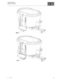
Manufacturers of Agricultural Machinery Hi-Spec Vertical Feeder Operators Manual 2011 Models: V10, V12, V14, V16 T14, T16, T20, T24 rev – vf103 Hi-Spec Engineering Ltd. Station Rd, Bagenalstown, Co. Carlow Tel: +353 (0) 59 -9721929 / 9721992 Fax: +353 (0) 59 -9721980 Website: www.hispec.net E-mail: [email protected] Vertical Feeder Operators Manual __________________________________________________________________________________ 2 rev – vf103 Vertical Feeder Operators Manual __________________________________________________________________________________ Introduction Congratulations on Purchasing a Hi-Spec Vertical Feeder. Please Read the Following Manual Before Using Machine. The way you care for and maintain this machine will decide its future performance. This manual has been carefully written to help you maintain the condition of your machine. Read this manual carefully to learn how to operate and service your machine correctly. Failure to do so could result in personal injury or machine damage. Hi-Spec Vertical Feeders have been designed and manufactured in compliance with the following directives and standards; Machinery Directive 2006/42/EEC. Harmonised standards; EN ISO 12100-1:2003, Safety of machinery Part 1: Basic terminology, methodology EN ISO 12100-2:2003, Safety of machinery Part 2: Technical principles EN ISO 4254-1:2005, Agricultural machinery -- Safety -- Part 1: General requirements EN ISO 14121-1:2007, Safety of Machinery – Principle of Risk Assessment This manual should be kept within the vicinity of the machine at all times and should be considered a permanent part of your machine. It should remain with the machine should you decide to sell it. Warranty is provided as a part of Hi-Spec Engineering’s support program for customers who operate and maintain this machine and equipment as described in this manual. This warranty provides you the assurance that Hi-Spec Engineering will back its machines should defects appear within the warranty period. If the machine is abused, or modified to change its performance beyond the original factory specifications, the warranty will become void and improvements may be denied. All information, illustrations and specifications in this manual are based on the latest product information available at the time of publication. It is the policy of Hi-Spec Engineering to improve its products and designs whenever it is practical and possible to do so. We reserve the right to make changes or improvements at any time without incurring any obligation to make such changes on products sold previously Thank You for Choosing Hi-Spec Engineering rev – vf103 3 Vertical Feeder Operators Manual __________________________________________________________________________________ Contents Introduction ....................................................................................................... 3 Contents ............................................................................................................ 4 Designated Use of Machine............................................................................... 6 Technical Specifications and Dimensions .......................................................... 7 Safety ................................................................................................................. 8 Recognise Safety Information ................................................................. 8 General Safety ......................................................................................... 9 Safety Checklist ....................................................................................... 9 Description of Safety Warnings and Instructions.................................. 11 PTO Shaft Safety .................................................................................... 12 Getting Started ................................................................................................ 13 Tractor Requirements ........................................................................... 13 Connecting Feeder to Tractor ............................................................... 14 Fitting PTO Shaft.................................................................................... 15 Road Transportation........................................................................................ 16 Operating Instructions ..................................................................................... 17 General Instructions .............................................................................. 19 Ladder Operation .................................................................................. 21 Counter Knife Operation ....................................................................... 22 Hydraulic Counter Knives ...................................................................... 23 Manual Counter Knives ......................................................................... 24 Loading Instructions ........................................................................................ 25 Feedout Instructions........................................................................................ 26 Vertical Feeder Equipped with One Door with Teaser and Manually Adjusted Chute Height. ......................................................... 26 Vertical Feeder Equipped with Two Feedout Doors with Teasers and Manually Adjusted Chute Height. .................................................. 28 Vertical Feeder Equipped with One Feedout Door with Teaser and Hydraulic Chute. .................................................................................... 30 Vertical Feeder Equipped with Two Feedout Doors with Teasers and Hydraulic Chutes. ........................................................................... 32 Vertical Feeder equipped with Cross Conveyor .................................... 34 4 rev – vf103 Vertical Feeder Operators Manual __________________________________________________________________________________ Vertical Feeder equipped with Cross Conveyor and Elevator............... 36 Vertical Feeder equipped with VHD Cross Conveyor ............................ 38 Vertical Feeder equipped with Straw Blower ....................................... 40 Vertical Feeder Equipped with One Feedout Door with Teaser and Elevator ................................................................................................. 42 Vertical Feeder Equipped with Two Feedout Doors with Teasers, One Elevator and One Chute................................................................. 45 DINACOM 2 Hand Control Unit ....................................................................... 46 Troubleshooting for DINACOM2 Hand Control Unit ............................. 48 Dinacom2 Hand Control Unit Basic Layout ........................................... 51 Position of EV Driver Unit ...................................................................... 51 Maintenance.................................................................................................... 52 Correct Maintenance and Inspection Procedures ................................ 52 Recommended Maintenance ................................................................ 53 Gearbox Maintenance ........................................................................... 54 Elevator Maintenance ........................................................................... 55 Greasing Points on Feeder .................................................................... 56 Troubleshooting .............................................................................................. 58 How to Adjust the Pressure Sequence Valves ...................................... 59 Electrical Faults...................................................................................... 59 Vertical Auger Feeder Hydraulic & Electrical Control box Details ................... 60 Sales and Service ............................................................................................. 61 Warranty.......................................................................................................... 62 Conditions of Sale ............................................................................................ 63 Registration Forms .......................................................................................... 66 Registration Forms .......................................................................................... 68 Declaration of Conformity ............................................................................... 70 rev – vf103 5 Vertical Feeder Operators Manual __________________________________________________________________________________ Designated Use of Machine The Hi-Spec Vertical Feeder is exclusively designed to mix and dispense feed in a controlled environment, e.g. level stable ground such as a cattle shed, using low power requirements and low maintenance costs. Ensure the machine is level to get the best results while mixing. Hi-Spec Engineering will not be held responsible for any loss or damage resulting from machine applications other than those specified above. Any other use the machine may be put to is entirely at the owners/operators risk. The Designated use of a Vertical Feeder includes that the operating, maintenance and repair instructions given by the manufacturer will be strictly fulfilled. Designated use means operating the Vertical Feeder is exclusively for persons familiar with the machine and fully aware of the associated risks involved in operating it. By any alteration of safety equipment, the Declaration of Conformity, as well as the CE sign on machine loses it validity 6 rev – vf103 Vertical Feeder Operators Manual __________________________________________________________________________________ Technical Specifications and Dimensions Model Single Auger Capacity m3 V10 10 V12 12 V14 14 V16 16 Twin Auger m3 T14 14 T16 16 T20 20 T24 24 rev – vf103 Height (H) Width (W) Length (L) Body Height (A) Body Length (B) Track Width (T) Feedout Height (F) Unladen Weight mm (ft) mm (ft) mm mm mm mm mm kg 2910 (9’7”) 3060 (10’) 2910 (9’7”) 3110 (10’2”) 2860 (9’5”) 2860 (9’5”) 3270 (10’9”) 3270 (10’9”) 5110 1600 3500 2190 800 4700 355/50-22.5 5160 1750 3600 2190 800 5000 355/50-22.5 5550 1600 3900 2540 800 5900 355/50-22.5 5600 1800 4000 2540 800 6400 355/50-22.5 mm (ft) mm (ft) mm mm mm mm mm kg 2700 (8’9”) 2975 (9’9”) 2820 (9’3”) 3020 (9’11”) 2465 (8’1”) 2465 (8’1”) 2860 (9’5”) 2860 (9’5”) 6520 1750 5070 1940 800 6000 6570 1800 5210 1940 800 6500 7332 1600 5850 2400 800 7260 7532 1800 6050 2400 800 7660 Wheel Size 235X75R17.5 235X75R17.5 235X75R17.5 235X75R17.5 7 Vertical Feeder Operators Manual __________________________________________________________________________________ Safety The Hi-Spec Vertical feeder has been designed with many safety features built in to its design but ultimately, safe operation and maintenance is the responsibility of the operator. Recognise Safety Information This is a safety alert symbol. When you see this symbol on your machine or in this manual, be alert to the potential for personal injury Follow the recommended guidelines for safe operating practice: Understand signal words: - On machine safety signs, signal words give the level of the hazard Danger Indicates an imminently hazardous situation which, if not avoided, will result in death or serious injury Warning Indicates a potentially more hazardous situation which, if not avoided, could result in death or serious injury Caution Indicates a potentially hazardous situation which, if not avoided, may result in minor or moderate injury You will find these signs located near specific hazards on your machinery Please pay attention to these signs for your own safety Safety signs should be maintained and replaced when necessary. They can often become dirty, torn or unreadable due to dirt and wear and tear If you need a replacement sign or have lost your user manual, please contact your Hi-Spec authorised dealer or Hi-Spec Engineering directly and we would be happy to issue you with a replacement 8 rev – vf103 Vertical Feeder Operators Manual __________________________________________________________________________________ General Safety Keep a first-aid kit and a fire extinguisher close by at all times, if possible, on your tractor with this operator instruction manual. Have an emergency plan. Keep all emergency numbers close by; write them into your manual. Inspect your machine carefully each time before use; this will only take a minute. Always climb the ladder and check inside the machine before starting or filling it, to make certain it is empty. Stop machine when leaving unattended. Children should never be in the area when your Feeder is in operation. Using a Vertical Feeder is a one-man operation therefore there should be no other person(s) in the vicinity of the machine while in use. Remember that the first step to avoiding danger is to recognise the hazards. Safety Checklist Always disconnect all power sources before carrying out any adjustment or maintenance. Always check inside the machine to make sure it is empty. Always check around the machine making sure everything is in order; this will only take a minute. Study this manual. Provide training to new users. Like all farm machinery, any machine is potentially dangerous when under the control of untrained personnel. Exercise extreme care when loading feed and additive into the machine. Always ensure guards and other safety devices are kept in good working order. Replace if necessary. Keep clear of all moving parts. Always connect the shear bolt end of the PTO shaft to the tractor. Always use shear bolts recommended to you by Hi-Spec Engineering. Always keep all hydraulic hoses and electric cables clear from PTO shaft. Always apply the handbrake before unhitching and park the machine in a level area. rev – vf103 9 Vertical Feeder Operators Manual __________________________________________________________________________________ Always use ladder for mixing inspection point. Do not climb up the side of the machine. Remember to fold up ladder after each inspection. Always take extra precautions when using the machine on hilly or sloping ground. 10 X Never permit young persons or spectators to operate PTO driven equipment or stand anywhere close by when the machine is in operation. X Never permit untrained personnel to operate the machine without reading this manual and or receiving training. X Never operate the machine without having all guards in place; they are there for your safety and protection against serious injury and death. X Never remove guards while there is still power going into the machine, all power must be off! X Never enter the machine while in operation. X Never wear loose clothes when operating machinery, if standing too close, your clothing can pull you into the machine. X Never operate the machine if you think there could be large stones or foreign objects inside, they could cause serious damage to your machine. X Never leave the machine running when unattended. X If the machine should become blocked with a stone or foreign object, X Do not attempt to free the object while the tractor is running. rev – vf103 Vertical Feeder Operators Manual __________________________________________________________________________________ Description of Safety Warnings and Instructions The following is a list of safety signs and warning labels on the Hi-Spec Vertical Feeder. Look carefully and make sure you know where on the machine they are positioned and what they mean. It is important you are fully aware of the areas of risk on your machine. Keep a safe distance from the revolving Rotor while feeder is in operation. General danger sign. There is a danger of rotating parts and foreign objects. Keep clear of machine while working. This safety sign is to remind the operator to disengage the PTO before turning Do not stand between the machine and the tractor while the PTO is in operation. Keep clear of machine while working. rev – vf103 11 Vertical Feeder Operators Manual __________________________________________________________________________________ PTO Shaft Safety The PTO shaft is a vital link in driving the machine. It is also a very dangerous piece of equipment, therefore it is important to follow the manufacturer’s guidelines on maintenance and repair. These guidelines are fixed to the PTO when new. They should be removed, read carefully and then stored with this instruction manual for future reference. If the guidelines are missing from the PTO Shaft please contact your Hi-Spec dealer for another copy. The irregular shape and connection joints of a turning shaft can cause serious injury. The rotational force of the shaft is the main hazard. Do not wear loose fitting clothing or articles such as jewellery that might get caught in a turning PTO. The rotation of the PTO is 540 rpm when mixing. Accidents can happen very fast therefore keep a safe distance from the shaft when it is in use. PTO Shafts account for most of tractor related fatalities. Make sure the shaft is guarded. Replace the guards when they are Damaged or missing. Never use the machine with Damaged or missing guards In an emergency situation, take the PTO Out of gear, stop the engine and set the brake. 12 rev – vf103 Vertical Feeder Operators Manual __________________________________________________________________________________ Getting Started Tractor Requirements Horsepower The horsepower needed to power a Vertical Feeder depends on the size of the Feeder and more so the main use of the Feeder. Hydraulic Requirements A minimum of two double acting spool valves are required to operate a standard Vertical Feeder. The hydraulic hoses are colour coded for your convenience and are as follows. Door Operation Green – Door Open Blue – Door Close Door Operation c/w Hyd. Counter Knifes Green – Counter knife out and Door open (if linked) Blue – Door close and Counter knife in (if linked) When using Solenoid Block and Handset Red – Pressure Green – Return More details on hydraulic operations are outlined further in “Operating Instructions”. rev – vf103 13 Vertical Feeder Operators Manual __________________________________________________________________________________ Connecting Feeder to Tractor Adjustment of Drawbar Use a pickup hitch or a short drawbar. Have the machine parked on a level area. Adjust the height of the bolt on hitch and/or drawbar to ensure the machine is level when attached to the tractor. The following diagram shows the different height options available. * Please note: Drawbar Adjustment Not Available on Twin Auger Models 14 rev – vf103 Vertical Feeder Operators Manual __________________________________________________________________________________ Fitting PTO Shaft Turn the tractor to full lock to either the left or right to get the shortest point of the PTO shaft. Slide the PTO apart and fit the half with the shear bolt to the tractor and the other end to the machine. Lift the two parts of the PTO shaft up so that they are level with each other. Mark 150 mm (6″) back from each other as shown in the diagram below. Cut off the excess profile. rev – vf103 15 Vertical Feeder Operators Manual __________________________________________________________________________________ Road Transportation Before bringing your machine onto a public road, it is important to check thoroughly that the machine is following all of the appropriate guidelines. Ensure brakes are connected and working correctly Ensure lights are connected and working correctly Ensure PTO is disengaged and electronic readout is switched off Observe local maximum road speeds for this type of machine Hi-Spec Engineering strongly recommend extreme care to be taken by the operator when travelling on rough roads with a loaded Machine as shock loads will damage the weighbars. Owners and/or operators do so at their own risk. The operator must ensure that any other regulations regarding road use are adhered to. Extreme care must be taken when negotiating acute bends with high speed tractors. 16 rev – vf103 Vertical Feeder Operators Manual __________________________________________________________________________________ Emergency Breakaway Handbrake The emergency breakaway handbrake should be connected to the tractor every time the diet feeder is been used. It should be done using the wire rope provided. The wire rope should be attached to a solid part of the tractor like the top link pin and not to a panel on the tractor. The wire rope should be tight enough so it will work effectively if the diet feeder became detached from the tractor but loose enough that the handbrake is not been applied during normal operation. Handbrake in the off position Handbrake in the on position rev – vf103 17 Vertical Feeder Operators Manual __________________________________________________________________________________ Disengaging the Emergency breakaway handbrake It is disengaged by following the steps below: Make sure the clip in front of the ratchet is facing forward or turned away from the gearbox on the feeder. If the clip is turned towards the gearbox the ratchet mechanism will not release. Push the handle towards the feeder so the ratchet becomes tight against the teeth that hold it in place. Pull the handle away from the feeder so the ratchet will disconnect itself from the teeth. Push the handle back to it original off position. WARNING: It is important to check that the handbrake be fully released when the tanker is in use. If the brake is left half applied it will cause damage to the brakes on the diet feeder. 18 rev – vf103 Vertical Feeder Operators Manual __________________________________________________________________________________ Operating Instructions General Instructions Before using your Vertical Feeder always walk around it making sure everything in order, this only takes a minute. Inspect the mixing chamber, making sure it is empty of any foreign material. Remember to put the ladder back into the transport position once you have finished with it. See Ladder Instructions for further details. Inspect the gearbox oil reservoir for oil. When the level is between the indicated guides, there is sufficient oil in the gearbox, see Fig.18 for details. Make sure the on/off valve on the gearbox is in the open position; see Fig. 15 of gearbox maintenance for details. Make sure the machine is on a level surface. Fill to max level indicator and let oil filter thru system. (Please note this may take some time) Ensure that the feedout doors are closed fully and the counter knives are at the correct setting using the stoppers provided. See counter knife settings for further details. When you are satisfied everything is as it should be connect the PTO to the tractor. Secure the PTO guard at both ends using the safety chains provided. Ensure the shear bolt end is always towards the tractor. Fig: -18 rev – vf103 19 Vertical Feeder Operators Manual __________________________________________________________________________________ Connect all Hydraulic pipes to the tractor, inc. the brake pipe. Connect the lights plug (seven pin) to the power supply on the tractor. Connect the weigher plug (single pin) to the 12 volt power supply on the tractor. If the Vertical Feeder comes complete with a control box connect the weigher plug (single pin) and the operation plug (three pin) to the control box provided, see Fig. 12. Connect the power cable from the control box to the 12 volt power supply in the tractor cab. When the machine is not in use the control box or handset must be unplugged from the tractor power supply. The Vertical Feeder hydraulics use electrical power when in operation and if left plugged in while the tractor and Vertical Feeder are not in operation it may drain your tractor battery. Adjust the weigher control to the required setting; see your weigher operator manual for details. Do not attempt to adjust your weigher system without referring to the operator manual, which has been supplied to you with your machine. On Vertical Feeders equipped with a two speed gearbox the high speed should be used for normal operation. If however the operating tractor has not adequate power then the low speed should be selected. Tractors with more than 70 HP should have no difficult operating in the high speed. When filling the mixing chamber, ensure the Vertical Feeder is reasonably level. For Vertical Feeders equipped with manually adjusted chute height the height of the chute should be set before loading of the Vertical Feeder. To adjust the height of the chute for the first time remove the chain from the door using the joining link provided. Open the feedout door to the maximum. Set the required height of the chute using the chain and joining link by connecting it to the door. The feedout door can now be closed again and the chute should return to its transport position. You are now ready to engage the PTO and increase its speed to 540 rpm for chopping and mixing. 20 rev – vf103 Vertical Feeder Operators Manual __________________________________________________________________________________ Ladder Operation The ladder at the rear of the Feeder is provided to assist the operator to view the load while it is mixing and to assist the operator as to when the mixing is complete. When not in use the ladder should always be folded into the transport position to avoid unnecessary damage. No person should use the ladder while the Feeder is being loaded. Ladder Transport Position Ladder Work Position rev – vf103 21 Vertical Feeder Operators Manual __________________________________________________________________________________ Counter Knife Operation The counter knives on your Vertical Feeder are operated in one of three of the following ways, manually, hydraulically or hydraulic sequence. If no chopping is required only mixing the counter knifes should be retracted fully and the setting handles or pins should be in position 6. For manual operation use the pin provided to set the desired position of your counter knives. It is only possible to set this position with the vertical feeder empty. For hydraulic operation use the pin provided to set the maximum depth the counter knives can protrude into the body of your vertical feeder. For hydraulic sequence of the counter knives on your vertical feeder the counter knives are operated in sequence with the operation of the feedout doors. The sequence is as follows:- Counter knives retract fully from inside the body before the feedout door begins to open and subsequently the feedout door closes fully before the counter knives protrudes into the body. It is necessary to hold the hydraulic lever in the on position for a few seconds after the door is closed in order to set the counter knives in the pre set position. For chopping of silage bales the best results are usually obtained with the counter knives retracted fully, position 6. Occasionally better results can be achieved by using positions 4 or 5. For chopping of hay or straw bales without silage bales positions 2 or 3 usually work best. For mixing of concentrates the counter knives should be retracted fully. Because of the unique design of the Hi-Spec auger the following conditions obtain the best results when using the Vertical Feeder. 22 • All of the material in the Vertical Feeder should be moving. • If the material is stopping or the tractor is coming under pressure the counter knives are in too far and should be withdrawn. • If the material is moving at the same speed as the auger then the counter knives should be let in one position. rev – vf103 Vertical Feeder Operators Manual __________________________________________________________________________________ Hydraulic Counter Knives Counter Knife Fully Out Counter Knife Fully In rev – vf103 23 Vertical Feeder Operators Manual __________________________________________________________________________________ Manual Counter Knives Counter Knife Fully Out Counter Knife Fully In 24 rev – vf103 Vertical Feeder Operators Manual __________________________________________________________________________________ Loading Instructions With the Vertical Feeder running load the ingredients in the following order. Straw Hay Bale silage Pit silage Maze Concentrates Minerals In order to obtain maximum chopping and mixing it is recommended to fill the machine to at least 50% of its volume capacity. When the loading of ingredients is finished inspect the load for quality of chopping and or mixing before discharging the feed mix. When loading is finished and you are satisfied with the quality of the chopping and mixing disengage the PTO and proceed to the feeding area. rev – vf103 25 Vertical Feeder Operators Manual __________________________________________________________________________________ Feedout Instructions Vertical Feeder Equipped with One Door with Teaser and Manually Adjusted Chute Height. 1. Position the tractor and Vertical Feeder at the start of the feedout area in a straight line an appropriate distance away from stock, Fig. 6 2. The required height of the chute should have been set. See “General Instructions” for more details. 3. Using tractor spool-valve 1 open the feedout door to the desired height. The chute should also rise to the pre set height, see Fig 9. For most applications we recommend opening the feedout door to the maximum height to obtain an even feedout. 4. Set up the tractor in the desired forward gear to advance for discharge. 5. Engage the PTO and increase its speed to 540 rpm. 6. The rate of feedout is controlled by the ground speed of the tractor and where applicable the opening height of the feedout door. 7. When the load has been discharged, close the feedout doors and return the chute to its lower transport position, see Fig. 6. In summary the sequence is as follows: Select feedout side. Open feedout door. Set tractor gear. Engage PTO. 26 rev – vf103 Vertical Feeder Operators Manual __________________________________________________________________________________ rev – vf103 27 Vertical Feeder Operators Manual __________________________________________________________________________________ Vertical Feeder Equipped with Two Feedout Doors with Teasers and Manually Adjusted Chute Height. 1. Position the tractor and Vertical Feeder at the start of the feedout area in a straight line an appropriate distance away from stock, Fig. 6 2. The required height of the chute should have been set. See “General Instructions” for more details. 3. Using the Handset open the required feedout door to the desired height. The chute should also rise to the pre set height, see Fig 9. For most applications we recommend opening the feedout door to the maximum height to obtain an even feedout. 4. To feedout from a second feedout door use tractor spool-valve 2 and open the second feedout door to the desired height. 5. Set up the tractor in the desired forward gear to advance for discharge. 6. Engage the PTO and increase its speed to 540 rpm. 7. The rate of feedout is controlled by the ground speed of the tractor and where applicable the opening height of the feedout door. 8. When the load has been discharged, close the feedout doors and return the chutes to their lower transport positions, see Fig. 6. In summary the sequence is as follows: Select feedout side. Open feedout door. Select second feedout side. Open feedout door. Set tractor gear. Engage PTO. 28 rev – vf103 Vertical Feeder Operators Manual __________________________________________________________________________________ rev – vf103 29 Vertical Feeder Operators Manual __________________________________________________________________________________ Vertical Feeder Equipped with One Feedout Door with Teaser and Hydraulic Chute. 1. Position the tractor and Vertical Feeder at the start of the feedout area in a straight line an appropriate distance away from stock, Fig. 6. 2. If your Vertical Feeder is equipped with only one feedout door and hydraulic chute there will be a control box fitted. Use switch to change operation between Door and Chute. 3. Using tractor spool-valve 1, adjust the chute to the desired height, see Fig. 7. 4. Using tractor spool valve 2, open the feedout door to the desired height. The counter knives will retract fully first, Fig. 8. When the feed mix has a high percentage of forage we recommend opening the feedout door to the maximum height to obtain an even feedout, see Fig. 9. When the feed mix has a high percentage of concentrates then opening the door about half way should be adequate. 5. Set up the tractor in the desired forward gear to advance for discharge. 6. Engage the PTO and increase its speed to 540 rpm. 7. The rate of feedout is controlled by the ground speed of the tractor and where applicable the opening height of the feedout door. 8. When the load has been discharged, close the feedout door and return the chute to its lower transport positions, see Fig. 6. 9. On tractors with a two speed PTO the 1,000 RPM PTO speed can be used to empty the Vertical Feeder when there is 1,000 kg of feed remaining in the Vertical Feeder. This will speed up the emptying procedure. In summary the sequence is as follows: Select feedout side. Adjust chute height. Open feedout door. Select second feedout side. Adjust chute height. Open feedout door. Set tractor gear. Engage PTO. 30 rev – vf103 Vertical Feeder Operators Manual __________________________________________________________________________________ rev – vf103 31 Vertical Feeder Operators Manual __________________________________________________________________________________ Vertical Feeder Equipped with Two Feedout Doors with Teasers and Hydraulic Chutes. 1. Position the tractor and Vertical Feeder at the start of the feedout area in a straight line an appropriate distance away from stock, Fig. 6. 2. Using the Dinacom2 Hand Control Unit, Fig. 20, (For Details of Button Functions on Dinacom2 Hand Control Unit see page 44), select the side from which you wish to feedout the mix from. 3. Using Dinacom2 Hand Control Unit, Fig. 20, adjust the chute to the desired height, see Fig. 7. 4. Using Dinacom2 Hand Control Unit, Fig. 20, open the feedout door to the desired height. The counter knives will retract fully first, Fig. 8. When the feed mix has a high percentage of forage we recommend opening the feedout door to the maximum height to obtain an even feedout, see Fig. 9. When the feed mix has a high percentage of concentrates then opening the door about half way should be adequate. 5. Set up the tractor in the desired forward gear to advance for discharge. 6. Engage the PTO and increase its speed to 540 rpm. 7. The rate of feedout is controlled by the ground speed of the tractor and where applicable the opening height of the feedout door. 8. When the load has been discharged, close the feedout doors and return the chutes to their lower transport positions, see Fig. 6. 9. On tractors with a two speed PTO the 1,000 RPM PTO speed can be used to empty the Vertical Feeder when there is 1,000 kgs of feed remaining in the Vertical Feeder. This will speed up the emptying procedure. In summary the sequence is as follows: Select feedout side. Adjust chute height. Open feedout door. Select second feedout side. Adjust chute height. Open feedout door. Set tractor gear. Engage PTO. 32 rev – vf103 Vertical Feeder Operators Manual __________________________________________________________________________________ rev – vf103 33 Vertical Feeder Operators Manual __________________________________________________________________________________ Vertical Feeder equipped with Cross Conveyor 1. Position the tractor and Vertical Feeder at the start of the feedout area in a straight line an appropriate distance away from stock. 2. Using the Dinacom2 Hand Control Unit, Fig. 20, (For Details of Button Functions on Dinacom2 Hand Control Unit see page 44), select the side from which you wish to feedout the mix from (fig. 34). 3. Using Dinacom2 Hand Control Unit, adjust the conveyor to the required position and set the conveyor to the required speed. 4. Using the Dinacom2 Hand Control Unit open the feedout door to the desired height (fig. 35). When the feed mix has a high percentage of forage we recommend opening the feedout door to the maximum height to obtain an even feedout, see Fig. 9. When the feed mix has a high percentage of concentrates then opening the door about half way should be adequate. 5. Set up the tractor in the desired forward gear to advance for discharge. 6. Engage the PTO and increase its speed to 540 rpm. 7. The rate of feedout is controlled by the ground speed of the tractor and where applicable the opening height of the feedout door. 8. When the load has been discharged, close the feedout door. 9. On tractors with a two speed PTO the 1000 RPM PTO speed can be used to empty the Vertical Feeder when there is 1000 kgs of feed remaining in the Vertical Feeder. This will speed up the emptying procedure. In summary the sequence is as follows: Select feedout side. Adjust conveyor. Set conveyor speed Open feedout door. Set tractor gear. Engage PTO. 34 rev – vf103 Vertical Feeder Operators Manual __________________________________________________________________________________ rev – vf103 35 Vertical Feeder Operators Manual __________________________________________________________________________________ Vertical Feeder equipped with Cross Conveyor and Elevator 1. Position the tractor and Vertical Feeder at the start of the feedout area in a straight line an appropriate distance away from stock. 2. Using the Dinacom2 Hand Control Unit, Fig. 20, (For Details of Button Functions on Dinacom2 Hand Control Unit see page 44), select the side from which you wish to feedout the mix from (fig. 30). (If choosing to feed out from side without elevator, leave elevator in the upright position and turn off) 3. Using Dinacom2 Hand Control Unit, adjust the conveyor to the required position and set the conveyor to the required speed. 4. Set elevator to required height (fig. 32). 5. Using Dinacom2 Hand Control Unit, open the feedout door to the desired height (fig. 33). When the feed mix has a high percentage of forage we recommend opening the feedout door to the maximum height to obtain an even feedout, see Fig. 9. When the feed mix has a high percentage of concentrates then opening the door about half way should be adequate. 6. Set up the tractor in the desired forward gear to advance for discharge. 7. Engage the PTO and increase its speed to 540 rpm. 8. The rate of feedout is controlled by the ground speed of the tractor and where applicable the opening height of the feedout door. 9. When the load has been discharged, close the feedout door. 10. On tractors with a two speed PTO the 1000 RPM PTO speed can be used to empty the Vertical Feeder when there is 1000 kgs of feed remaining in the Vertical Feeder. This will speed up the emptying procedure. In summary the sequence is as follows: Select feedout side. Adjust conveyor. Set conveyor speed. Adjust elevator. Open feedout door. Set tractor gear. Engage PTO. 36 rev – vf103 Vertical Feeder Operators Manual __________________________________________________________________________________ rev – vf103 37 Vertical Feeder Operators Manual __________________________________________________________________________________ Vertical Feeder equipped with VHD Cross Conveyor 1. Position the tractor and Vertical Feeder at the start of the feedout area in a straight line an appropriate distance away from stock. 2. Using the Dinacom2 Hand Control Unit, Fig. 20, (For Details of Button Functions on Dinacom2 Hand Control Unit see page 44), select the side from which you wish to feedout the mix from. Press the 3. button for the direction and position required (fig. 51). Engage the tractor spool to ensure a soft start for the belt Note: Do not engage the tractor spool before pressing on the electrical controller button. This will cause the belt to start too quickly and the drive sprockets to slip. 4. When feeding out, the speed of the belt should be fast enough to prevent any build up of meal at the door. The belt speed is set by adjusting the flow control knob on the side of the hydraulic box (fig. 52). 5. Using Dinacom2 Hand Control Unit, open the feedout door to the desired height. When the feed mix has a high percentage of forage we recommend opening the feedout door to the maximum height to obtain an even feedout. When the feed mix has a high percentage of concentrates then opening the door about half way should be adequate. 6. Set up the tractor in the desired forward gear to advance for discharge. 7. Engage the PTO and increase its speed to 540 rpm. 8. The rate of feedout is controlled by the ground speed of the tractor and where applicable the opening height of the feedout door. 9. When the load has been discharged, close the feedout door. 10. On tractors with a two speed PTO the 1000 RPM PTO speed can be used to empty the Vertical Feeder when there is 1000 kgs of feed remaining in the Vertical Feeder. This will speed up the emptying procedure. In summary the sequence is as follows: Select feedout side. Adjust conveyor. Engage Tractor Spool. Set conveyor speed. Open feedout door. Set tractor gear. Engage PTO. 38 rev – vf103 Vertical Feeder Operators Manual __________________________________________________________________________________ Conveyor care • To prevent problems with the belt drive and sprocket wear, the belt must be washed thoroughly once a month to reduce build-up of meal. This can be done by raising the conveyor on one side and hosing the belt as it turns. • Grease the conveyor slide regularly. • It is normal for the belt to sag; the belt must never be tensioned to remove all sag. • The centre pivot points and the lifting arms use igus bearings and do not require grease. rev – vf103 39 Vertical Feeder Operators Manual __________________________________________________________________________________ Vertical Feeder equipped with Straw Blower 1. Position the tractor and Vertical Feeder at the start of the feedout area in a straight line an appropriate distance away from stock. 2. Using the Dinacom2 Hand Control Unit, Fig. 20, (For Details of Button Functions on Dinacom2 Hand Control Unit see page 44), extend the chute flap up/down (fig. 41). 3. Adjust the angle of the blower chute left/right to the required position (fig. 42). 4. Once the required chopping length has been achieved. 5. Using Dinacom2 Hand Control Unit, open the feedout door to the desired height. When the mix has a high percentage of forage we recommend opening the feedout door to the maximum height to obtain an even feedout. 6. Set up the tractor in the desired forward gear to advance for discharge. 7. Engage the PTO and increase its speed to 540 rpm. 8. The rate of feedout is controlled by the ground speed of the tractor and where applicable the opening height of the feedout door. 9. When the load has been discharged, close the feedout door and return the chutes to their lower transport positions 10. On tractors with a two speed PTO the 1000 RPM PTO speed can be used to empty the Vertical Feeder when there is 600 kgs of straw remaining in the Vertical Feeder. This will speed up the emptying procedure. In summary the sequence is as follows: Adjust position of chute flap. Adjust angle of chute. Open feedout door. Set tractor gear. Engage PTO. 40 rev – vf103 Vertical Feeder Operators Manual __________________________________________________________________________________ rev – vf103 41 Vertical Feeder Operators Manual __________________________________________________________________________________ Vertical Feeder Equipped with One Feedout Door with Teaser and Elevator 1. Before entering the feedout area set the switch on the control box to Elevator transport to work position, ELEV. UP/SLIDE, see Fig. 12. 2. If your Vertical Feeder is equipped with only one feedout door and elevator there will be a control box fitted. Use switch to change function between Door and Elevator. 3. Using tractor spool-valve 1 to move the elevator from the transport position to the work position, see Fig. 1 and Fig. 2 on page 25. 4. Position the tractor and Vertical Feeder at the start of the feedout area in a straight line an appropriate distance away from stock. 5. Using tractor spool-valve 1 again to set the elevator at the required height, see Fig. 3. 6. Using tractor spool-valve 2 open the feedout door to the desired height. If the Vertical Feeder is equipped with hydraulic operated counter knives then the counter knives will retract fully first, see Fig. 4. Then the feedout door opens, see Fig. 5. 7. Set the switch on the control box to elevator feedout position to operate the elevator motor, ELEV. FEEDOUT, see Fig. 12. This will set tractor spool-valve 1 to drive the elevator chains for feedout. 8. Set up the tractor in the desired forward gear to advance forward for discharge. 9. Using tractor spool-valve 1 drive the elevator in the correct direction. The speed of the elevator can be adjusted from the side of the feeder using the flow control valve, see Fig.17. 10. Engage the PTO and increase its speed to 540 rpm. 11. The rate of feedout is controlled by the forward speed of the tractor, the speed of the elevator and where applicable the opening height of the feedout door. 12. When the load has been discharged, close the feedout doors and return the elevator to the transport position, Fig. 1. 42 rev – vf103 Vertical Feeder Operators Manual __________________________________________________________________________________ rev – vf103 43 Vertical Feeder Operators Manual __________________________________________________________________________________ In summary the sequence is as follows: Set elevator to work position. Set elevator height. Open feedout door. Set control box to elevator feedout. Set tractor gear. Start elevator. Engage PTO. Proceed forward feeding out. Disengage PTO. Close feedout door. Stop elevator Return elevator to transport position. ! Take care as you move the elevator from work to transport position and vice versa as it can cause injury to onlookers. 44 rev – vf103 Vertical Feeder Operators Manual __________________________________________________________________________________ Vertical Feeder Equipped with Two Feedout Doors with Teasers, One Elevator and One Chute Using the Dinacom2 Hand Control Unit, Fig. 20, select the side from which you wish to feedout the mix from, i.e. elevator side or chute side, LEFT SIDE or RIGHT SIDE. As standard the elevator will be fitted on the right side and the chute on the left side. To feedout using the elevator refer to elevator instructions. To feedout using the chute refer to chute instructions. rev – vf103 45 Vertical Feeder Operators Manual __________________________________________________________________________________ DINACOM 2 Hand Control Unit 12 Button Functions DOOR OPEN 2 1 1DOOR CLOSE 2- 4 3- 4- DISCHARGE ROLLER FOR FEED OUT DISCHARGE ROLLER REVERSE ELEVATOR DOWN 3 5ELEVATOR UP 6CONVEYOR FEED 7- 11 7 8 14 13 5 6 10 8- 9- 101112- 9 REVERSE CONVEYOR FEED CONVEYOR LEFT OR DOOR CLOSE CONVEYOR RIGHT OR DOOR OPEN POWER EMERGENCY BUTTON 13- BATTERY INDICATOR 14- COMMUNICATION ERROR INDICATOR ** Please note: Button Groups are for individual doors, depending on number of doors fitted. See table for more details. 46 rev – vf103 Vertical Feeder Operators Manual __________________________________________________________________________________ For feeders fitted with a single door Left door Right door Group 2 Group 3 For Feeders fitted with multiple doors Front Left door Front Right door Back Right door Back Left door Group 2 Group 3 Group 4 Group 1 For feeders fitted with a cross conveyor, its functions will be controlled by button group 4 Warning Lights Emergency Function In case of problem or emergency press the button. When you press the emergency button ALL MOVEMENTS ARE STOPPED IMMEDIATELY. When the emergency button is pressed, the red indicators are ON. To restart the system it is necessary to disconnect the power supply cable for a number of seconds and reconnect it. Alarms COMMUNICATION ERROR RED Light Is turned on when there are problems on the communication between the DinaCom2 Hand Control Unit and EV Driver Unit. (Example – damaged cable) BATTERY VOLTAGE GREEN Light Is turned ON when the system is turned ON and the voltage of the battery is no more than 9Vdc. When the LED is OFF, the battery voltage is under 9Vdc and it is necessary to change or recharge it. rev – vf103 47 Vertical Feeder Operators Manual __________________________________________________________________________________ Troubleshooting for DINACOM2 Hand Control Unit If the DInaCom2 Hand Control Unit is unresponsive and Emergency Lights are On. (For position of EV Driver unit see page 49) 1. CHECK THE FUSE. If the fuse is blown or missing, the red light is turned ON. If the fuse is ok and you have a Communication Error Light 2. CHECK THE CABLE CONNECTION IN THE CONTROL UNIT 48 rev – vf103 Vertical Feeder Operators Manual __________________________________________________________________________________ If a Function is not Working Properly by Pressing a Button. 1. CHECK THE LIGHT ON THE OUTPUT CABLE. 2. CHECK THE LIGHT ON THE EV DRIVER BOARD. When a function is working, its red light on the EV Driver board is turned ON. 3. CHECK THE POWER SUPPLY ON THE EV BOARD. If the power supply is working, there are 2 red lights turned ON. rev – vf103 49 Vertical Feeder Operators Manual __________________________________________________________________________________ 4. CHECK THE FUSE. If the fuse is blown or missing, the red light is turned ON. CHECK THE EMERGENCY CONDITION. When the system is in the EMERGENCY CONDITION its red light is turned ON and the power supply red lights are turned OFF. 50 rev – vf103 Vertical Feeder Operators Manual __________________________________________________________________________________ Dinacom2 Hand Control Unit Basic Layout Position of EV Driver Unit rev – vf103 51 Vertical Feeder Operators Manual __________________________________________________________________________________ Maintenance In order to maintain your Vertical Feeder in peak working order it is necessary to carry out routine maintenance. The following will give you details of the procedures and frequency required. Correct Maintenance and Inspection Procedures Learn how to service your machine correctly. Follow the correct maintenance and inspection procedures shown in this manual. Inspect the machine daily before starting. Walk around the machine checking general appearance. Check for loose or missing parts. Always disengage the PTO and stop the tractor engine before greasing and making any adjustments. Never operate the machine without safety guards in position. Caution During operation, some parts of the hydraulic system can become hot; allow the machine to cool down before beginning inspection or maintenance procedures. If there is a problem with your machine, repair it before operating or contact your authorised dealer or Hi-Spec Engineering. Maintenance Safety Extreme caution must be taken when performing maintenance or repairs to the Hi-Spec Vertical diet feeder. The machine must be disconnected from all power sources (ie. tractor) before any maintenance or repair work is carried out. It is the responsibility of the operator to ensure that a safe system of work is in place before any maintenance or repair procedures. The mixing chamber is a particular hazard. It contains a large number of knives for cutting fibres in the diet mix. The cutting knives are bolted to the mixing auger and are positioned horizontally. The floor of the mixing chamber is extremely slippy. Before performing any work within the mixing chamber the operator must cover the cutting surface of all knives and ensure they have a good base to provide a solid footing. 52 rev – vf103 Vertical Feeder Operators Manual __________________________________________________________________________________ Recommended Maintenance The following is a maintenance list recommended for your machine by Hi-Spec Engineering to ensure your Feeder is kept in peak condition. After the First Use and then after 25 hours: Check all nuts for tightness. Check tyre pressure. Check tightness of road wheel nuts. Recommended tyre pressures are as follows. Wheel size Pressure 40x14.5-19 5.0 Bar 30x11.5-14.5x 6.0 Bar 235/75 R17.5 twin 7.0 Bar 385/55 R19.5 5.5 Bar Every 50 hours: Check oil reservoir container for gearbox. Grease door slides. Check Auger Knives. Every 100 hours: Grease points… Grease points on hydraulic elevator. Grease points on hydraulic elevator ram. Grease points on the hydraulic door ram. Grease points on PTO shaft, also pull apart and grease sliding tube. Check tyre pressures and road wheel nuts. Check tightness of gearbox mounting nuts and auger mounting nuts. Check elevator chains for slackness and adjust if necessary. Yearly maintenance: Check the hydraulic pipes for any frays or fractures and replace if necessary. Check the wheel bearings for any slackness and adjust if required. Remove the hubcap and fill with grease. Ensure the weighbar bolts are tightened to the proper torque. M24 x 130 Bolts 400 Nm M30 x 200 Bolts 40 Nm Note: The large bolt (M30) should never be over tightened as this will cause the weighing system to read inaccurately. rev – vf103 53 Vertical Feeder Operators Manual __________________________________________________________________________________ Gearbox Maintenance Routine Maintenance After the first 25 hours, check that the fixing bolts are properly tightened and that everything is correctly aligned. Every 200 hours, the oil level should be checked and lubricant added if required. Changing the Oil Lubrication The first oil change should be carried out after a minimum of 50 or a maximum of 100 working hours. At the first oil change, we recommend that the gear case be washed out with diesel to flush out any microscopic debris. The breather and magnetic drain pugs should be cleaned at every oil change. Other oil changes should be made every 2500 working hours and at least once a year. If in doubt contact Hi-Spec Engineering or your Hi-Spec Dealer. Under the feeder you will find an on/off valve on the gearbox, (Fig.15). Before operating your machine, ensure the valve is open (Fig.15). This valve is to assist you in changing gearbox oil and also in the event of the oil bottle becoming damaged it can be turned off to prevent further leakage (Fig.16). 54 rev – vf103 Vertical Feeder Operators Manual __________________________________________________________________________________ Elevator Maintenance Adjustment of chain and slat elevator Chain and slat type elevators need adjustment if the chains become excessively loose due to normal wear. Adjustment is achieved by tightening or loosening the adjusters that are locked on the side of the elevator. 1. Slacken the bolts fixing the adjustment plates to the elevator body. 2. Release the lock nuts (1) and using the adjuster nuts (2), tighten the chains equally. 3. Adjust a small amount at a time, ¼ turn adjustment each time is recommended. 4. Adjust so that the chain is firm but still a small amount of slackness to pull the chain by hand. 5. Replacement chains should be fitted when excess wear has occurred to insure the smooth running of your machine. Caution Do not over tighten chains. Breakage of chains may occur if over tightened. Fig: - 19 Greasing and Maintenance Points on Elevator Arm Slide bar Hydraulic rams Bearing Motor Hydraulic hoses rev – vf103 55 Vertical Feeder Operators Manual __________________________________________________________________________________ Greasing Points on Feeder No. Machine Part 1. Counter Knife Rams 2. Door Rams 3. Door Slides 4. Chute Rams 5. PTO Shafts 6. Elevator 7. Elevator Arm 8. Elevator Ram This symbol is found on each greasing point on the machine. Maintenance Points on Feeder No. Machine Part 1. Tyre Pressures 2. Road Wheel Nuts 3. Auger Knives 4. Auger Gearbox 5. Two Speed Gearbox 6. Oil Reservoir 7. Weighbar Bolts 8. Hydraulic Pipes 56 rev – vf103 Vertical Feeder Operators Manual __________________________________________________________________________________ Greasing and Maintenance Points on Feeder 2 3 14 5 13 4 1 5 15 11 2 3 12 5 10 9 6 rev – vf103 8 57 Vertical Feeder Operators Manual __________________________________________________________________________________ Troubleshooting Feed out elevator hydraulics * Read the sequence valve instructions listed at on page 58 before attempting to make any adjustments. ** To identify each sequence valve please see the diagram on page 59. 1. Problem: Elevator will move to the door position but will not drop to the feedout position. 2. 3. Solution: Reduce the pressure setting in pressure sequence valve no. 1. Problem: Elevator begins to drop before it reaches the door. Solution: Increase the pressure setting in the pressure sequence valve no. 1. Problem: Elevator folds up at the door but will not return to the transport position. 4. Solution: Reduce the pressure setting in the pressure sequence valve no. 2 Problem: Elevator begins to return to the transport position before it has folded up fully. 5. Solution: Increase the pressure setting in the pressure sequence valve no. 2. Problem: Counter knives go out but door does not open or is very slow to open. 6. 58 Solution: Reduce pressure setting in valve 3. Problem: Door closes but counter knives will not go into body. Solution: Reduce pressure setting in valve 4. rev – vf103 Vertical Feeder Operators Manual __________________________________________________________________________________ How to Adjust the Pressure Sequence Valves 1. Remove the cap using a no. 17 spanner. 2. Release the lock nut using a no. 17 spanner. 3. To reduce the pressure setting use a no. 6 hex key and turn the adjuster anti-clockwise (an eighth to a quarter of a turn is usually adequate). 4. To increase the pressure setting, turn the adjuster clockwise (an eighth to a quarter of a turn is usually adequate). 5. Re-tighten the lock nut. 6. Replace the cap. Electrical Faults 1. Faults: - *Left hand door doesn’t open. - *Left hand hydraulic chute doesn’t work. - Elevator motor doesn’t work. Possible Causes: - No electrical power reaching solenoids. - Solenoids faulty. Check: - Power supply from tractor. - Fuse in the control box. - Cable connections within the 3 pin plug. - Electrical cables for damage. - Cable connections at solenoid. * Applies to a Vertical Auger Feeder fitted with twin discharge doors only. rev – vf103 59 Vertical Feeder Operators Manual __________________________________________________________________________________ Vertical Auger Feeder Hydraulic & Electrical Control box Details B A 4 3 21 Type 1 C Index: A: Solenoid diverter valve for feedout chutes. B: Solenoid diverter valve for feedout doors. C: Solenoid diverter valve for elevator D: Solenoid valve block E: EV Driver box 1,2,3,4: Sequence valves – see below: 1: 2: Elevator into work position | Elevator down Elevator up | Elevator into the transport position 3: Counter knives out | Door/s open 4: Doors closed | Counter knives in E 2 1 D 60 Type 2 rev – vf103 Vertical Feeder Operators Manual __________________________________________________________________________________ Sales and Service Ireland Head office Hi-Spec Engineering Ltd., Station Rd, Bagenalstown, Co. Carlow, Ireland Tel: - +353 59 9721929 Fax: - +353 59 9721980 Email: - [email protected] or [email protected] After Sales Service Contact: - Brian McArdle, Hi-Spec Engineering Ltd. Tel: - +353 87 2562963 Email: - [email protected] Machine Servicing Contact: - Michael Brennan, Hi-Spec Engineering Ltd. Tel: - +353 87 2403312 Spare Parts Store Contact: Mike Nolan or Terence Byrne, Hi-Spec Engineering Ltd. Tel: - +353 59 9721929 Fax: - +353 59 9721980 Email: - [email protected] U.K. After Sales service: Wales, Midlands & South West England Contact: - George Reed, Hi-Spec Engineering Ltd. Tel: - +44 7802 652139 Email: [email protected] East & South East England Contact: - John Molton, Hi-Spec Engineering Ltd. Tel: - +44 7825 330887 Email: - [email protected] Northern England & Scotland Contact: - Paul McUrick, Hi-Spec Engineering Ltd. Tel: - +44 7810 040100 Email: - [email protected] For spare parts Contact: - Your local Hi-Spec dealer. If you require a contact name and number you can telephone head office and we would be glad to assist you. rev – vf103 61 Vertical Feeder Operators Manual __________________________________________________________________________________ Warranty The following is a list of warranty terms. Warranty claims will be disallowed if they do not fall into the categories shown here. Warranty Terms 1 Year Warranty on Drive System, Bearings and Elevator Chain. 2 Years Warranty on Weighing System NO Warranty on the following: PTO Shafts Hydraulic fittings Hydraulic hoses ς Electrical connections between machine and tractor NO Warranty allowed for breakdowns due to: Misuse of the machine, e.g. overloading by the operator Lack of maintenance, e.g. failure to carry out regular oiling and greasing of components and bearings where appropriate 62 rev – vf103 Vertical Feeder Operators Manual __________________________________________________________________________________ Conditions of Sale General In these conditions the word “Company” means Hi-Spec Engineering Limited. The word “dealer” means a customer of Hi-Spec Engineering Ltd. Purchasing machines from them for resale at recommended retail prices and the word “first user” means the first person to whom the dealer sells any goods for actual use. The company’s employees may negotiate orders and issue quotations but an order is only binding on a company when it has acknowledged the order in writing on the company’s official acknowledgement forms. Such acknowledgement and confirmation will only be given subject to these conditions of sale. The acceptance of delivery of the goods either at the dealer’s premises or those of the first user if delivered direct to the first user shall bind the dealer and the dealer shall only sell to the first user on conditions which incorporate the company’s warranty. If he fails to sell the dealer shall have no claim whatsoever against the company except insofar as the company will honour the warranty to the dealer and through him to the first user. The term goods where used means such articles as are invoiced by the company whether manufactured, imported, distributed or otherwise sold by them. Delivery Should the company be prevented from delivering any goods owing to any lockout, strike, weather conditions, or other exceptional causes occurring either at their own premises, or elsewhere, then delivery shall be postponed until a reasonable time after the occurrence has seized to cause delay, unless the parties shall mutually serge to the cancellation of the contract in respect of such goods. Cancellation of Orders The only ground for acceptance of a cancellation of an order shall be the non acceptance of these terms and conditions by the dealer and then only if Within seven days of receiving notification of the terms and conditions the dealer notifies the company in writing of its non-acceptance. The dealer pays the company any losses suffered included any carriage charges if these have been incurred. Delays While every effort has been made to adhere to delivery dates or times quoted by the company, such dates or times given though given in good faith are mere estimates only. The company accepts no responsibility for delay in delivery or for the consequences of such delay however caused nor shall the dealer be entitled to reject goods thereof by reason. rev – vf103 63 Vertical Feeder Operators Manual __________________________________________________________________________________ Design No responsibility is accepted for any deviation from drawings or from illustrations in catalogues, price lists, brochures or advertising material for discrepancies in weight, rated outputs. Performance from those mentioned here in which shall be treated as illustrative and approximate only. Price Any fluctuation in prices arising after the contract but before dispatch shall entail adjustment in the contract price and the price to be paid shall be fixed at the date of dispatch. Damage, Shortage or Loss The company do not accept any responsibility for any damage, shortage or loss in transit when goods are dispatched to instructions and where the transit is affected through a third party and not by the Company itself. Conditions of Resale The dealer shall only re-sell any of the company’s products with the full and unaltered warranty that is issued with every machine invoiced by the company. If the dealer either through negligence or for any other cause fails to get the agreement of the first user to accept this warranty the dealer shall have no other recourse against the company except that contained in these conditions of sale. The dealer expressly agrees that in accepting delivery he has no recourse in law against the company nor will he join the company as third or other party in any action which results against him from the resale of the company’s products. Warranty The Company warrants its products through the dealer and through the dealer to the first user. The dealer shall only re-sell the company’s machines with the benefit of the company’s warrants. The said warranty is as follows: The company warrants, subject as hereinafter provided, that all new goods supplied by it shall be free from defects in material and workmanship, its liability under such warranty being limited to making good at a factory to be nominated by it, such parts or parts (which shall be within twelve calendar months from the date which the product was delivered new to the retail purchaser) be returned to the company or its authorised representative which the company is satisfied on its examination of the part or parts to have been defective in material or workmanship provided that. All replaced parts shall become the property of the company. 64 rev – vf103 Vertical Feeder Operators Manual __________________________________________________________________________________ The foregoing warranty does not extend to any product which shall have been repaired, altered, neglected or used in any way so as, in the judgement of the company (whose decision is final) may have adversely affected its stability or reliability, nor does this warranty apply to proprietary articles, accessories or parts not manufactured by the company but where any such warranty is given by the manufacturers of such articles, accessories or parts any benefits under such warranty will be passed on by the company. The company will not be responsible for damage or loss caused by incorrect machine settings, ground speed or operation of the machine in unsuitable conditions and the company’s decision as to the suitability of the condition shall be final. Fair wear and tear is excluded from any claim and no responsibility whatsoever is accepted for damage, which in the company’s Opinion is caused by hazards of soil, stones of foreign objects. The warranty is transferable to a second or subsequent owner (within the warranty period) subject to the company being notified in writing of this change of ownership. Complaints referring to faulty or incomplete deliveries or to obvious faults must be notified to the dealer in writing within fourteen days after receipt of goods. In the absence of such notification delivery shall be considered as having been accepted as in good order and condition. The company does not give any warranty in respect of its goods except therefore going Warranty which is given expressly in lieu of and excludes all other warranties and conditions expressed or implied whether under common law, Statue or otherwise and every form of liability for loss or damage direct or consequential or for any accidents resulting from defective material faulty workmanship or otherwise, is expressly excluded. Liability In no circumstances whatsoever shall the Company’s liability (in contract, tort or otherwise) to a buyer under, out of or in connection with this contract or the goods supplied exceed the invoice price of the particular goods in regard to which component is made. Title of the Goods The title in the goods shall not pass to the customer until the customer shall have discharged all sums due by the customer to the company at the date of the final handing over of the possessions of goods Interest If the customer shall fail to pay any sum due in foot of this transaction within fourteen days after the same shall become due, the customer shall pay interest thereon calculated from the due date of payment at the annual rate equal to 4% over the prime rate charged from time to time by the associated banks on secured loans to individual customers. rev – vf103 65 Vertical Feeder Operators Manual __________________________________________________________________________________ Registration Forms Hi-Spec Engineering Ltd. Station Rd., Bagenalstown, Co. Carlow, Ireland Tel: - 059 9721929 Fax: - 059 9721980 Please complete the following forms in full. The first is a warranty registration form; this form is issued in accordance with our conditions of sale and with particular reference to the condition governing warranty. We cannot process a claim unless all particulars are supplied. The second is an acceptance form, which the purchaser is asked to sign to acknowledge he/she has received a copy of the Operator manual and full training for the machine purchased. Please do not sign if you have not received both of these. Warranty Registration Date of Purchase: ____________________ Purchaser’s Name: ____________________ Signature: ____________________ Address: ____________________________________________ Phone: ____________________ Dealer’s Name: ____________________ Signature: ____________________ Address: ____________________________________________ Phone: ____________________ Machine Type: Vertical Feeder _______ Machine Model: ____________________ Serial Number: ____________________ Training & Operator Manual Registration Please sign the following declaration to state that on the day you (the purchaser) purchased a HiSpec Vertical Feeder you received an operator manual and training instructions. I the purchaser have received my Hi-Spec Vertical Feeder Operator Manual and training from the below dealer. Purchaser: Signature: Date: Dealer: Signature: Date: This copy is to be kept in your manual for your reference. 66 rev – vf103 Vertical Feeder Operators Manual __________________________________________________________________________________ rev – vf103 67 Vertical Feeder Operators Manual __________________________________________________________________________________ Registration Forms Hi-Spec Engineering Ltd. Station Rd., Bagenalstown, Co. Carlow, Ireland Tel: - 059 9721929 Fax: - 059 9721980 Please complete the following forms in full. The first is a warranty registration form; this form is issued in accordance with our conditions of sale and with particular reference to the condition governing warranty. We cannot process a claim unless all particulars are supplied. The second is an acceptance form, which the purchaser is asked to sign to acknowledge he/she has received a copy of the Operator manual and full training for the machine purchased. Please do not sign if you have not received both of these. Warranty Registration Date of Purchase: ____________________ Purchaser’s Name: ____________________ Signature: ____________________ Address: ____________________________________________ Phone: ____________________ Dealer’s Name: ____________________ Signature: ____________________ Address: ____________________________________________ Phone: ____________________ Machine Type: Vertical Feeder _______ Machine Model: ____________________ Serial Number: ____________________ Training & Operator Manual Registration Please sign the following declaration to state that on the day you (the purchaser) purchased a HiSpec Vertical Feeder you received an operator manual and training instructions. I the purchaser have received my Hi-Spec Vertical Feeder Operator Manual and training from the below dealer. Purchaser: Signature: Date: Dealer: Signature: Date: This copy is to be posted to Hi-Spec Engineering or given to your dealer 68 rev – vf103 Vertical Feeder Operators Manual __________________________________________________________________________________ rev – vf103 69 Vertical Feeder Operators Manual __________________________________________________________________________________ Declaration of Conformity EC Machinery Directive 2006/42/EC We hereby certify that the machinery stipulated below complies with all relevant provisions of the EC Machinery Directive and the National Laws and Regulations adopting this Directive. Modifications to the machine without prior approval from the undersigned will render this declaration null and void. Machine Description and Function: Vertical Feeder designed to mix and dispense feed Make: Hi-Spec Model: V10, V12, V14, V16, T14, T16, T20, T24 Serial Number: Manufacturer: Hi-Spec Engineering Ltd. Address: Station Rd, Bagenalstown, Co. Carlow, Ireland Technical file compiled by: Derek Whelan, Myshall, Co. Carlow Harmonised standards applied: EN ISO 12100-1:2003, Safety of machinery Part 1: Basic terminology, methodology EN ISO 12100-2:2003, Safety of machinery Part 2: Technical principles EN ISO 4254-1:2005, Agricultural machinery -- Safety -- Part 1: General requirements EN ISO 14121-1:2007, Safety of Machinery – Principle of Risk Assessment Signed: __________________________________ Date: 6th April 2010 Name: Mike Nolan Position: Managing Director Being the responsible person appointed by the manufacturer. Hi-Spec Engineering reserve the right to make changes and improvements at any time without incurring any obligation to make such changes on products previously sold. 70 rev – vf103 Vertical Feeder Operators Manual __________________________________________________________________________________ rev – vf103 71 Vertical Feeder Operators Manual __________________________________________________________________________________ Auger Knife Replacement List 72 rev – vf103 Vertical Feeder Operators Manual __________________________________________________________________________________ Augers (After June 2007) Model : VTF10 / 12 / 14 / 16 / T20 / T24 1 2 2 2 2 3 4 Part No. Description VF/0025 Complete auger (please state machine model & year) Auger cap 1 2 VF/0009 Small auger knife 3 VF/0068 Auger knife 1 4 VF/0069 Auger knife 2 5 VF/0070 Auger knife 3 rev – vf103 73 Vertical Feeder Operators Manual __________________________________________________________________________________ Augers VTF T14 / T16 2 2 1 2 2 2 2 Part No. Description VF/0025 Complete auger (please state machine model & year) Auger cap 1 2 74 VF/0009 Knife rev – vf103 Vertical Feeder Operators Manual __________________________________________________________________________________ Notes rev – vf103 75