1
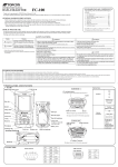
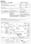
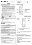
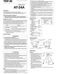
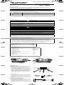
AT-G4(E).fm Page 1 Tuesday, May 2, 2006 8:49 PM
INSTRUCTION MANUAL
AUTO LEVEL
AT-G4
AT-G6
Foreword
Thank you for purchasing the TOPCON GREEN LABEL Auto Level AT-G Series.
For the best performance of the instruments, please read these instructions
carefully and keep them in a convenient location for future reference.
General Handling Precautions
• Before starting work or operation, be sure to check that the instrument
is functioning correctly with normal performance.
Display for safe use
In order to encourage the safe use of products and prevent any danger to the
operator and others or damage to properties, important warnings are put on the
products and inserted in the instruction manuals.
We suggest that everyone understand the meaning of the following displays and
icons before reading the “Safety Cautions” and text.
Display
Meaning
WARNING
Ignoring or disregard of this display may lead to death or
serious injury.
CAUTION
Ignoring or disregard of this display may lead to personal
injury or physical damage to the instrument.
1) Injury refers to hurt, burn, electric shock, etc.
2) Physical damage refers to extensive damage to buildings or equipment
and furniture.
Safety Cautions
WARNING
• Cause eye injury or blindness.
Do not look at the sun through a telescope.
It is suggested to pay care specially at the time the position of the sun is
low such in the morning or evening, or at the time the sunlight is coming
directly to the objective lens of the instrument, cut off the sunlight by your
hand or use an umbrella in such case.
• Do not use the staff in conditions of thunder and lightening.
As this is an electric conductor, thunderbolt can cause serious injury or
death.
• Keep the staff away from electric facilities such as a high voltage
wire or substation.
As this is an electric conductor, there is danger of electric shock.
CAUTION
Risk of injury by overturn the carrying case.
Do not stand or sit on the carrying cases.
Please note that the tips of tripod can be hazardous, be aware of this
when setting up or carrying the tripod.
Risk of injury by falling down the instrument or case.
Do not use a carrying case with a damaged which belts, grips or latches.
A plumb bob can cause an injury to a person if used incorrectly.
Ensure that you mount the Tribrach correctly, failing to do so may result in
injury if the tribrach were to fall over.
It could be dangerous if the instrument falls over, please check that you
fix the instrument to the tripod correctly.
Risk of injury by falling down a tripod and an instrument.
Always check that the screws of tripod are tightened.
User
1) This product is for professional use only!
The user is required to be a qualified surveyor or have a good knowledge of surveying,
in order to understand the user and safety instructions, before operating, inspecting or
adjusting.
2) Wear the required protectors (safety shoes, helmet, etc.) when operating.
Exceptions from Responsibility
1) The user of this product is expected to follow all operating instructions and make
periodic checks of the product’s performance.
2) The manufacturer, or its representatives, assumes no responsibility for results of a
faulty or intentional usage or misuse including any direct, indirect, consequential
damage, and loss of profits.
3) The manufacturer, or its representatives, assumes no responsibility for consequential
damage, and loss of profits by any disaster, (an earthquake, storms, floods etc.).
A fire, accident, or an act of a third party and/or a usage any other usual conditions.
4) The manufacturer, or its representatives, assumes no responsibility for any damage,
and loss of profits due to a change of data, loss of data, an interruption of business etc.,
caused by using the product or an unusable product.
5) The manufacturer, or its representatives, assumes no responsibility for any damage,
and loss of profits caused by usage except for explained in the user manual.
6) The manufacturer, or its representatives, assumes no responsibility for damage caused
by wrong movement, or action due to connecting with other products.
Standard set component
Model AT-G4 or AT-G6 ............................ 1each
Plastic carrying case ................................ 1each
Lens cap .................................................. 1each
Plumb bob set........................................... 1each
Hexagonal wrench.................................... 1each
Silicon cloth .............................................. 1each
Vinyl cover ................................................ 1each
Instruction manual .................................... 1each
Specifications
Telescope
Overall length ............................................. 192mm(AT-G4)
193mm(AT-G6)
Image ......................................................... Erect
Effective diameter lens ............................... 30mm
Magnification .............................................. 26X(AT-G4)
24X(AT-G6)
Field of view ............................................... 1°30'
Resolving power ......................................... 3.5"(AT-G4)
4"(AT-G6)
Minimum focus ........................................... 0.5m
Horizontal circle
Diameter ..................................................... 117mm
Minimum reading ........................................ 1°
Automatic compensation mechanism
Range .............................................. ±15'
Measuring accuracy
1 km double run .................................. ±2.0mm
Circular level
Sensitivity ................................................... 8'/2mm
Other
Protection against water and dust .............. IPX7
(Based on the standard IEC60529)
Weight
Instrument .................................................. 1.6kg
Plastic carrying case .................................. 1.3kg
Nomenclature
Sighting collimator
Focusing knob
Eyepiece
Circular level viewing prism
Objective lens
Circular level
Horizontal knob
Base plate
Horizontal circle
Leveling screw
Operating
Setting
1 First position the tripod leg and then
2
3
4
5
spread the other two so as to make
the tripod head almost level.
Firmly position the tripod legs on the
ground, then tighten the screws.
Place the instrument on the tripod
head, then screw the tripod screw
into the instrument bottom for securing it to the tripod.
Use a plumb bob to match the instrument center with the measuring point
when a horizontal scale is used.
Use the three leveling screws to center the circular level. When a dome
head tripod is used loosen the tripod
screw a little, slide the instrument,
center the bubble, looking at the
level, then the tripod screw to secure
the instrument.
Tripod head
Leveling
screw
Tripod
screw
Fixing
screw
Leg
Adjuster
Plumb bob
Measuring point
Collimating
Circular level
1 Direct the telescope to bright object
and turn the eyepiece ring so that the
reticle in the telescope is clearly seen.
2 Turn the instrument manually and
align the target through the sighting
collimator.
3 Focus the target with the focusing
knob.
4 Turn the horizontal knob to match the
reticle with the target.
Measuring (Height)
• In order to measure the difference in height
between point A and point B.
1 Set up the instrument almost in the
middle of the points.
2 Provide a leveling rod at point A and
B, one each, collimate them and read
the horizontal line of the reticle.
3 Suppose the reading at point A is a
and that at point B id b, and the difference in height between the two points
will be: a - b
Target
Collimator
AT-G4(E).fm Page 2 Tuesday, May 2, 2006 8:49 PM
Note:
Be sure that the leveling rods are almost vertical.
It is recommended to position the level almost in the center of points A and B to
avoid influence by the axis of vision on the measuring even if it varies a little in
terms of being horizontal.
Measuring (Horizontal angle)
The horizontal circle has a clockwise graduation from 0° to 359° (0 to 399g)
numeric indications every 10 degrees (10g).
1 Attach the plumb bob string to the plumb bob hook and adjust the string length.
2 Loosen the tripod screw a little, and move the instrument according to the apex
to match the plumb bob end with the measuring point.
3 Re-tighten the tripod screw.
4 Use the leveling screws to center the circular level.
5 Sight target A and turn the horizontal circle to bring the scale to “zero”.
Sight target B, and then the reading 30° (33g) will be a horizontal angle
between points A and B.
Leveling (for 4 points)
1 Set up the instrument almost in the center of the 4 points.
2 Match the bottom of a rod with pile A marked line (a).
3 Sight the rod and mark (e) on the rod that coincides with the horizontal line of
the reticle.
4 Place the rod at B and move it vertically to sight the marked line (e).
5 Mark (b) in ink on pile B according to the rod bottom.
6 Mark piles C and D in the above manner.
Horizontal line
Checking and adjusting
Operation of the automatic compensating mechanism
1 Adjust the three leveling screw to center the circular level.
2 Sight the target, then strike the tripod slightly by hand.
3 The reticle may swing, but it will soon return to its position. This provides that
the mechanism is functioning
Checking and adjustment of the circular level
Checking
1 Operate the three leveling screws to center the circular level.
Turn the instrument 180°.
No adjustment is necessary if the bubble lines in the center circle. If not, take the following
measures for adjusting.
No adjustment is
necessary if the bubble
lines in the center circle.
Center circle
Turn the
instrument180°.
Adjusting
1 Use the hexagonal wrench to turn
the three circular level adjusting
screws to center the bubble by a half
that it is out-of-level.
2 Turn the three leveling screws to
bring the bubble to the center.
Check the instrument again by turning 180°, and adjustment is satisfactory if the bubble remains at the
center. If not, repeat the adjusting
procedure
Adjusting screws
Hexagona
l wrench
Leveling screw
Collimation of the instrument
Rear View
Checking
Front View
1 Place leveling rods A and B about 30
2
3
4
5
6
7
to 40 meters away from each other,
and set up the instrument with a tripod
almost in the middle between the
rods.
Use the leveling screws to center the
circular level.
Sight the rods for A and B reading.
(a1, b1)
Move the instrument to a position 2 to
3meters (7 to 8 feet) away from point
A.
Center the bubble again.
Sight the rods for reading again. (a2,
b2)
No adjustment should be necessary if the difference between to pairs of readings is equal: b1-a1=b2-a2.
If not, make the following adjustment.
Hexagonal wrench
Adjusting
1 Calculate b2'=a2+(b1-a1) and apply
to the rod farther away.Use adjusting
pin to turn the reticle adjusting screw
for collimating b'.
2 Follow “Checking” again, and confirm
that the adjustment is satisfactory.
Cover
TOPCON POSITIONING SYSTEMS, INC.
7400 National Drive, Livermore, CA 94551, U.S.A.
Phone: 925-245-8300 Fax: 925-245-8599 www.topcon.com
TOPCON CALIFORNIA
3380 Industrial Blvd, Suite 105, West Sacramento, CA 95691, U.S.A.
Phone: 916-374-8575 Fax: 916-374-8329
TOPCON SOUTH ASIA PTE. LTD.
Blk 192 Pandan Loop, #07-01 Pantech Industrial Complex, Singapore 128381
Phone: 62780222 Fax: 62733540 www.topcon.com.sg
TOPCON AUSTRALIA PTY. LTD.
Unit 18, 4 Avenue of Americas Newington NSW 2127, Australia
Phone: 02-8748-8777 Fax: 02-9647-2926 www.topcon.com.au
TOPCON INSTRUMENTS (THAILAND) CO., LTD.
TOPCON EUROPE POSITIONING B.V.
Essebaan 11, 2908 LJ Capelle a/d IJssel, The Netherlands.
Phone: 010-458-5077 Fax: 010-284-4949 www.topconeurope.com
IRELAND OFFICE
77/162 Sinn Sathorn Tower, 37th Fl.,
Krungdhonburi Rd., Klongtonsai, Klongsarn, Bangkok 10600 Thailand.
Phone: 02-440-1152~7 Fax: 02-440-1158
TOPCON INSTRUMENTS (MALAYSIA) SDN. BHD.
Unit 69 Western Parkway Business Center
Lower Ballymount Road, Dublin 12, Lreland
Phone: 01460-0021 Fax: 01460-0129
TOPCON DEUTSCHLAND G.m.b.H.
Giesserallee 31, 47877 Willich, GERMANY
Phone: 02154-885-100 Fax: 02154-885-111 [email protected]
www.topcon.de
TOPCON S.A.R.L.
89, Rue de Paris, 92585 Clichy, Cedex, France.
Phone: 33-1-41069490 Fax: 33-1-47390251 [email protected]
TOPCON ESPA„A S.A.
Excella Business Park Block C, Ground & 1st Floor, Jalan Ampang Putra,
Taman Ampang Hilir, 55100 Kuala Lumpur, MALAYSIA
Phone: 03-42701068 Fax: 03-42704508
TOPCON KOREA CORPORATION
2F Yooseoung Bldg., 1595-3, Seocho-Dong, Seocho-gu, Seoul, 137-876, Korea.
Phone: 82-2-2055-0321 Fax: 82-2-2055-0319 www.topcon.co.kr
TOPCON OPTICAL (H.K.) LIMITED
2-4/F Meeco Industrial Bldg., No. 53-55 Au Pui Wan Street, Fo Tan Road,
Shatin, N.T., Hong Kong
Phone: 2690-1328 Fax: 2690-2221 www.topcon.com.hk
Frederic Mompou 5, ED. Euro 3, 08960, Sant Just Desvern, Barcelona, Spain. TOPCON CORPORATION
Phone: 93-473-4057 Fax: 93-473-3932 www.topconesp.com
Building A No.9, Kangding Street
TOPCON SCANDINAVIA A. B.
BEIJING OFFICE
Beijing Economic Technological Development Area, Beijing, China 100176
Phone: 10-6780-2799 Fax: 10-6780-2790
Neongatan 2 S-43151 Mšlndal, SWEDEN
Phone: 031-7109200 Fax: 031-7109249
TOPCON CORPORATION BEIRUT OFFICE
TOPCON (GREAT BRITAIN)LTD.
Topcon House Kennet Side, Bone Lane, Newbury, Berkshire RG14 5PX U.K.
Phone: 44-1635-551120 Fax: 44-1635-551170
[email protected] [email protected]
P. O. BOX 70-1002 Antelias, BEIRUT-LEBANON.
Phone: 961-4-523525/961-4-523526 Fax: 961-4-521119
TOPCON CORPORATION DUBAI OFFICE
C/O Atlas Medical FZCO., P. O. Box 54304, C-25, Dubai Airport Free Zone,UAE
TOPCON CORPORATION
75-1 Hasunuma-cho, Itabashi-ku, Tokyo 174-8580, Japan
Phone: 3-3558-2520 Fax: 3-3960-4214 www.topcon.co.jp
1A
31745 90010