1
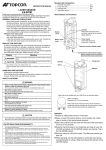
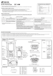
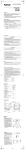
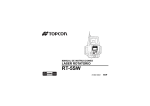
RL-100 1S
ENT
ESC
MENU
Y
INSTRUCTION MANUAL
ROTATING LASER
RL-100 1S
31486 90030
FCC WARNING
Changes or modifications not expressly approved by the manufacturer for compliance could void the user’s
authority to operate the equipment.
In order to comply with FCC radio-frequency radiation exposure guidelines for an uncontrolled exposure, this
device and its antenna must not be co-located or operating in conjunction with any other antenna or transmitter.
The term “IC:” before the radio certification number only signifies that Industry Canada technical specifications
were met.
“Operation of this device is subject to the following two conditions: (1) this device may not cause interference,
and (2) this device must accept any interference, including interference that may cause undesired operation of
the device.”
“The installer of this radio equipment must ensure that the antenna is located or pointed such that it does not
emit RF field in excess of Health Canada limits for the general population; consult Safety Code 6, obtainable
from Health Canada’s website www.hc-sc.gc.ca/rpb”.
Declaration of Conformity
Model Number:
Trade Name:
Responsible party:
Address:
Telephone number:
RL-100 1S
TOPCON CORPORATION
TOPCON POSITIONING SYSTEMS,Inc.
7400 National Drive, Livermore, CA 94550, U.S.A.
925-245-8300
This device complies with Part 15 of the FCC Rules. Operation is subject to the following two conditions:
(1) This device may not cause harmful interference, and (2) this device must accept any interference
received, including interference that may cause undesired operation.
Foreword
Thank you for purchasing the Topcon RL-100 1S Rotating Laser.
It is one the world’s most advanced and accurate grade-setting lasers. To quickly and effectively use
the RL-100 1S, please read these brief instructions carefully, and keep them in a convenient location
for future reference.
Handling Precautions
Guarding the instrument against shock
When transporting the instrument, provide some protection to minimize risk of shock. Heavy
shocks may affect beam accuracy.
Sudden changes of temperature
A sudden change in temperature may cause water condensation on the glass used for the laser
emission part.
In such a case, let the instrument stand for a while to allow it to adjust to the temperature prior to
actual use.
Caution:
Use of adjustment controls or performance procedures other than those specified herein may
results in hazardous radiation exposure.
1
Safety Information
In order to encourage the safe use of products and prevent any danger to the operator and others or
damage to properties, important warnings are put on the products and inserted in the instruction
manuals.
We suggest that everyone understand the meaning of the following displays and icons before
reading the “Safety Cautions” and text.
Display
Meaning
WARNING
Ignoring or disregard of this display may lead to death or serious injury.
CAUTION
Ignoring or disregard of this display may lead to personal injury or physical damage
to the instrument.
• Injury refers to hurt, burn, electric shock, etc.
• Physical damage refers to extensive damage to buildings or equipment and furniture.
The user of this product is expected to follow all operating instructions and make periodic checks
of the product’s performance. The manufacturer or its representatives assume no responsibility
for results of the use of this product including any direct, indirect, consequential damage, and loss
of profits.
2
Safety Cautions
WARNING
There is a risk of fire, electric shock or physical harm if you attempt to disassemble or repair the instrument
yourself.
This is only to be carried out by TOPCON or an authorized dealer, only!
Laser beams can be dangerous, and can cause eye injury if used incorrectly .
Never attempt to repair the instrument yourself.
Laser beams can be dangerous. They can cause eye injury.
Do not stare into beam or view directly with optical instruments.
High temperature may cause fire.
Do not cover the charger while it is charging.
Risk of fire or electric shock.
Do not use damaged power cable, plug and socket.
Risk of fire or electric shock.
Do not use a wet battery or charger.
Cause eye injury or blindness.
Do not look at the sun through a telescope.
May ignite explosively.
Never use an instrument near flammable gas, liquid matter, and do not use in a coal mine.
Battery can cause explosion or injury.
Do not dispose in fire or heat.
Risk of fire or electric shock.
Do not use any power voltage except the one given on manufacturers instructions.
Battery can cause outbreak of fire.
Do not use any other type of charger other than the one specified.
The short circuit of a battery can cause a fire.
Do not short circuit battery when storing it.
3
CAUTION
Use of controls or adjustment or performance of procedures other than those specified herein may result in
hazardous radiation exposure.
Do not connect or disconnect equipment with wet hands, you are at risk of electric shocks if you do!
Risk of injury by overturn the carrying case.
Do not stand or sit on the carrying cases.
Please note that the tips of tripod can be hazardous, be aware of this when setting up or carrying the tripod.
Risk of injury by falling down the instrument or case.
Do not use a carrying case with a damaged which belts, grips or latches.
Do not allow skin or clothing to come into contact with acid from the batteries, if this does occur then wash off
with copious amounts of water and seek medical advice.
It could be dangerous if the instrument falls over, please check that you fix the instrument to the tripod
correctly.
Risk of injury by falling down a tripod and an instrument.
Always check that the screws of tripod are tightened.
Let the laser beam reach the aimed object or the target without anybody else in the laser beam path. When
operating in an open area, avoid radiating laser beam at eye level. It is quite possible for the beam to enter into
one's eyes, and it is possible to lose visual sight temporarily, and lose one's caution and awareness of other
dangers - avoid glaring beam.
Please note that the tips of tripod can be hazardous, be aware of this when setting up or carrying the tripod.
Risk of injury by overturn the carrying case.
Do not stand or sit on the carrying cases.
4
EXCEPTIONS FROM RESPONSIBILITY
1) The user of this product is expected to follow all operating instructions and make periodic checks of the product’s
performance.
2) The manufacturer, or its representatives, assumes no responsibility for results of a faulty or intentional usage or
misuse including any direct, indirect, consequential damage, and loss of profits.
3) The manufacturer, or its representatives, assumes no responsibility for consequential damage, and loss of profits by
any disaster, (an earthquake, storms, floods etc.).
A fire, accident, or an act of a third party and/or a usage any other usual conditions.
4) The manufacturer, or its representatives, assumes no responsibility for any damage, and loss of profits due to a
change of data, loss of data, an interruption of business etc., caused by using the product or an unusable product.
5) The manufacturer, or its representatives, assumes no responsibility for any damage, and loss of profits caused by
usage except for explained in the user manual.
6) The manufacturer, or its representatives, assumes no responsibility for damage caused by wrong movement, or
action due to connecting with other products.
5
Laser Safety
Safety Information
This laser complies with all applicable portions of title 21 of the Code of Federal Regulations, Dept. of Health,
Education, and Welfare: Food and Drug Administration: Center for Devices: Bureau of Radiological Health.
Do not stare into the laser beam or view directly with optical instruments.
Do not disassemble the instrument or attempt to perform any internal servicing.
Repair and servicing of this laser are to be performed by TOPCON or its authorized dealer.
Caution : Use of adjustment controls or performance procedures other than those specified herein may result
in hazardous radiation exposure.
Visible laser
Laser output: 2.5mW
CLASS IIIa LASER PRODUCT
VISIBLE LASER BEAM
Beam Aperture
LASER RADIATION
AVOID DIRECT EYE EXPOSURE
WAVE LENGTH 685nm
5mW MAXIMUM OUTPUT
CLASS a LASER PRODUCT
6
Contents
Foreword .......................................................................................................................... 1
Handling Precautions................................................................................................. 1
Safety Information...................................................................................................... 2
Safety Cautions ........................................................................................................ 3
Laser Safety............................................................................................................... 6
Contents .................................................................................................................... 7
Standard System Components.................................................................................. 9
Nomenclature................................................................................................................. 10
Sample Display........................................................................................................ 12
Key Functions .......................................................................................................... 13
RL-100 1S LED Display ........................................................................................... 13
Basic Operation.............................................................................................................. 14
Preparation and Functions ............................................................................................. 15
Power Source .......................................................................................................... 15
Setting Up Instrument .............................................................................................. 15
Battery Status Display ............................................................................................. 16
Setting Grade........................................................................................................... 17
Aligning Direction of Grade...................................................................................... 18
How to Enter Grade ................................................................................................. 19
Menu .............................................................................................................................. 20
How to Set the Menu ............................................................................................... 20
Switching Masking Mode ......................................................................................... 22
Maintaining Power Sources ........................................................................................... 28
How to Change Batteries on the Instrument............................................................ 28
7
Check and Adjusting ...................................................................................................... 29
Horizontal Calibration .............................................................................................. 29
Horizontal Rotation Cone Error................................................................................ 33
Grade Setting Error.................................................................................................. 34
Storage Precautions....................................................................................................... 36
Standard/Optional Accessories...................................................................................... 40
Specifications ................................................................................................................. 45
Error Display .................................................................................................................. 47
FCC WARNING ............................................................................................................. 49
IC WARNING ................................................................................................................. 50
8
Standard System Components
1)
2)
3)
4)
5)
6)
7)
8)
Instrument ...............................................................1pc.
Level sensor LS-80B ...............................................1pc.
Level sensor holder model 6 ...................................1pc.
Carrying case ..........................................................1pc.
D size Manganese battery.....................................4pcs.
AA Manganese battery (To confirm operation)*.....2pcs.
Instruction manual ..................................................1vol.
Battery holder DB-67 ...............................................1pc.
• Please make sure that all of above items are in the box when you unpack.
* Batteries included in the package are to confirm the initial operation.
Please replace the batteries provided with new batteries as soon as possible.
9
Nomenclature
Rotary head/Laser emitting window
Beam aperture
Display
Handle
RL-100 1S
ENT
ESC
MENU
Y
Control panel
Battery holder DB-67
10
Battery compartment lock
Control panel
MENU key
Escape key
Y key
Enter key
RL-100 1S
ESC
ENT
Automatic leveling indicator
MENU
Y
Power switch
Arrow keys
11
Sample Display
Normal display
Y axis grade
(Blinks digit by digit
during leveling)
Transmission and
reception display
(On remote controller only)
Transmitting
Leveling indicator
(Blinks during leveling)
Rotation speed (rpm)
Battery remaining
Rotating laser display:
RL
Remote controller display: RC
Complete
Incomplete
Menu screen display
See “Menu” on page 20.
12
Key Functions
Enter key
End Operation of Data Input and Sends data to the instrument.
Escape key
Cancels input or escape to previous status.
Y key
Sets Y axis grade.
Menu and arrow keys
Selects menu items.
Inputs the grade of Y axis.
Sets the masking direction.
Power switch
On/Off of the RL-100 1S.
RL-100 1S LED Display
There is an LED that signals automatic alignment of the control panel screen of the main
instrument.
Flashing : Auto-leveling or grade setting is in process.
The rotary head is not rotating.
ON solid : Auto-leveling grade setting is complete.
The rotary head is active and emits the laser beam.
You can stop the auto-levelling function. Refer to “Menu” on page 20 to stop the
function.
13
Basic Operation
1
Set the instrument on a tripod or smooth surface
and turn on the power.
When using the remote controller, turn on the power for
the instrument, and then the power for the remote
controller.
Normal precision mode
High precision
mode
Level sensor
Higher than datum position
(Buzzer sound: High frequent
beep sound)
Move the sensor downward.
Set Y axis grade.
4
Check the rotating beam elevation using the level
sensor.
Turn on the level sensor. Check the operation
surface by using the level sensor. If high-precision
detection is desired, select that setting on the
level sensor.
Datum position
(Buzzer sound: Continuous
beep sound)
Lower than datum position
(Buzzer sound: Low frequent
beep sound)
Move the sensor upward.
14
2
3
(For more information about level sensor refer to
“Standard/Optional Accessories” section.)
Preparation and Functions
Power Source
Connect the battery according to the battery type purchased.
For charging and battery replacement instructions, see the “Maintaining Power sources” section.
Setting Up Instrument
Set the instrument on a tripod or smooth
surface.
The instrument must be within horizontal ±5
degrees of true level for auto-leveling to
operate.
RL-100 2S
ENT
ESC
MENU
X/Y
±5°
15
Battery Status Display
Remaining battery level is displayed at the lower bar in the display area.
Battery is sufficient.
Battery is sufficient.
Battery is sufficient.
The power is low, but laser is still usable. (Indication
continues until batteries are dead.)
Battery remaining display
Rotating laser display:
RL
Remote controller display: RC
RL-100 BATTERY Low
Dead batteries of RL-100 1S. Recharge the battery or
replace the dry batteries with new ones.
If an AC/DC converter is connected to the
main instrument when the main
instrument is displaying “RL-100
BATTERY LOW”, the remaining battery
level display will not change.
Once the power is turned off, the battery
remaining display will reset.
For handling batteries, see the “Maintaining Power Sources” on page 28.
16
Setting Grade
Grade can be set in Y axis, as shown below.
Grade can be set in the range indicated below.
Y: –5% to +25%
Grade axes and axis symbols are as shown in the diagram below.
+25%
Y axis
Plus
Minus
–5%
17
Aligning Direction of Grade
When using the laser with a percent of grade entered, the laser
must be properly aligned so the slope of the laser beam is
parallel to the desired direction of grade.
The sighting collimator on top of the instrument is calibrated to
the grade axis of the laser beam. Follow the steps below to align
the laser to the desired direction of grade:
18
1
2
Establish a target line parallel to desired direction of grade.
3
Rough align the instrument to the direction of grade. Make
sure it is properly oriented for the grade to be entered,
positive or negative. (See page 17)
4
5
Place a rod or other target down range on the target line.
RL-100
ESC
ENT
MENU
X/Y
Set up the laser over this line (drop a plumb bob from the
tripod mounting screw).
While sighting through
the collimator, adjust the
instrument until the sight
is aligned with the target.
(See the figures on the
right.)
Target
Plus direction
Minus direction
Single axis
Grade range:
Y: –5% to +25%
How to Enter Grade
1
2
3
4
5
Press the Y key to begin grade input.
The axis symbol will flash and it will go into grade entry
status.
Select positive or negative grade by pressing arrow
keys (Up or Down).
Y axis
Move the cursor by pressing the arrow keys (Right or
Left).
Increase or decrease the number by pressing the arrow keys (Up or Down).
Press the [ENT] key to finish input.
When setting up using the remote controller
Confirm the [OK].
If the [NG] mark is displayed, press the [ENT] key.
When holding down the [Y] key while the Y symbol is flashing, the flashing axis will reset
to 00.000%.
19
Menu
How to Set the Menu
As indicated by arrows in the figure, there are 6 setting categories in the menu and selection and
changes of the settings are performed using the arrow keys and [ENT] key.
1
2
3
4
5
Press the menu key to display the menu screen. As
you can see, the mask setting is framed with the
curser.
Changing Masking Mode
Changing rotary head speed
Move the curser to the item you would like to set up
using the arrow keys and press the [ENT] key. The
selected item will start flashing.
Select the setting details using the arrow keys.
Press the [ENT] key to lock the setting.
When setting up using the remote controller, make
sure that “OK” is displayed on the transmission and
reception display. If “NG” is displayed, press the
[ENT] key once again.
In the same manner, select and change the next
setting.
Alarm Signal (COM)
Safety Lock System
(Height Alert)
Sensitivity Level (LEVEL)
20
The menu allows setting of the following functions.
1) Changing Masking Mode 2) Changing rotary head speed
3) Sensitivity Level (LEVEL) 4) Safety Lock System (Height Alert)
5) Alarm Signal (COM)
1) Changing Masking Mode
Sets up masking (laser beam shut off) and change shut off directions.
Masking (Laser beam shutter) setting
Depending on the status of the location where the instruments are used, laser beam emission to
unnecessary direction can be shut off.
1
Press menu key to display the menu
screen.
The mask setting will be displayed on the
right in the upper side of the screen.
2
Use the arrow keys to position on the
Mask display and press the [ENT] key.
3
Select the direction you desire to mask
using the arrow keys.
Each press repeats mask activating/
releasing.
4
The state when masking is not activated
(Laser beams are emitted to all directions.)
When desired masking is displayed, press the [ENT] key to finish.
Confirm the [OK] mark on the display.
21
When setting up using the remote
controller
After completing 1 through 4 of the above
setting procedures, check that the transmission
and reception display is showing “OK”.
If the [NG] mark is displayed, press [ENT]
again. (“OK” and “NG” will be displayed only on
the remote controller screen.)
Displays the masking direction
Displays the direction that
laser beam is emitted.
The status in which the X+ direction is masked.
(Laser beam is shut off in the X+ direction.)
Switching Masking Mode
Mode 1
As seen
from above
Mode 2
As seen
from above
X axis
Y axis
You can select either Mode 1 or Mode 2 for the masking mode (split-masking direction).
The relationship between the arrow keys and masking directions are shown in the above figure.
22
Masking Mode Setting
1
2
3
Follow steps 1-2 for the masking setting.
Each press of [Y] key toggles Mask Mode 1 and Mask Mode 2.
Press the [ENT] key to lock the entry. When setting up with the remote controller, make sure
that “OK” is displayed on the transmission and reception display. If “NG” is displayed, press the
[ENT] key once again.
Sample display
Mode 1
Mode 2
2) How to change the rotary head speed (300, 600, 900 R.P.M.)
The rotary head speed can be set to 300, 600 or 900
R.P.M.
Press the menu key to display the menu screen. Use
the arrow keys to select the rotary head speed and
press the [ENT] key. When the head speed starts
flashing, select the desired speed using the arrow
keys and press the [ENT] key.
Rotation speed
23
3) Sensitivity Level (LEVEL)
The sensitivity level allows the user to select the vibration level that is permitted during
automatic alignment or grade setting. Set a sensitivity level to suit the location where the
instrument is used such as places that undergo many vibrations, and also in consideration of
the operational precision.
Two sensitivity levels can be set: large and small vibrations.
Manual setting will stop the automatic alignment function.
Large vibration
Small vibration
Manual
Do not use the manual setting for sensitivity level except in special
circumstances. If the manual setting is selected, the automatic alignment function
will not operate, so the grading setting precision will not be assured at all. The
manual setting will also deactivate the setting for Y-grade.
24
4) Safety Lock System (Height Alert)
In case the [ALERT] setting is ON. Safety Lock System will active. (This will be active around
10 minutes after turning on the power.)
Should the installed status of the instrument suddenly change when automatic alignment is
functioning and laser beam is being emitted, through, for example, unnecessary contact by the
user, the automatic alignment function will automatically stop to protect operational precision.
In such a case, the rotary head will act as below:
When [6) Warning transmission] is activated: it will rotate slowly
When [6) Warning transmission] in not activated: the rotation will stop
Active
Inactive
Error : Blinks alternately
How to reactivate
Turning off the power for the instrument, and then turning it back on will activate the automatic
alignment function.
25
5) Alarm Signal (COM)
When used with the Topcon laser sensor, the RL-100 1S can communicate alarm signals
directly to the sensor. This helps enable the user to be completely aware of potential
problems before they can become serious.
Active
Inactive
26
Concerning initial operation in a low temperature
When the instrument and remote controller is used in a temperature below -10°C, a warm up
operation of approximately 4 minutes is necessary for the LCD after the power is turned on.
During the warm up operation, no operation is possible except turning the power switch on/off.
The instrument will perform automatic alignment; however, when the automatic alignment has
been completed, the instrument will go into a standby state until the warm up operation is
completed (the rotary head is in a resting state).
After the warm up operation is completed, the instrument and remote controller will function
normally.
Warm up screen
Approximately
4 minutes later
During the warm up operation, the instrument will continue the operation even if the
power of the remote controller is turned off. (The instrument will not go into a
standby state.)
When the power is turned off after the warm up operation is completed, the
instrument will begin warm up operation again when the power is back on.
27
Maintaining Power Sources
How to Change Batteries on the Instrument
Dry battery
How to replace dry batteries
1
Remove the battery cover by turning the battery
cover knob to “OPEN”.
2
Remove the old batteries and replace with new
batteries (four D batteries) matching [+] and [-] as
shown in the figure.
3
Replace the battery cover and turn the knob to
“LOCK”.
Replace all 4 batteries with new ones.
Do not mix old batteries and new ones.
28
Check and Adjusting
Horizontal Calibration
(1) Checking Calibration
1 Steadily set up a tripod approximately 50m from a
staff member or wall and adjust so that the head
of the tripod is horizontal.
Mount the instrument on the tripod in the
direction shown in the right figure (Y-axis facing
the wall).
2 While pressing the [Y] key, turn on the power
switch.
3 The flashing axis is the selected one.
Select the axis to check using the arrow keys
(right and left) and press the [ENT] key to lock.
50m (164feet)
Level sensor
Staff or Wall
Turn on the power while pressing the [Y] key.
X Y
W X
Select the axis using the arrow keys (right and left)
and press the [ENT] key.
29
(Example: Y axis)
4 Select Y axis by pressing the right arrow key.
Press the [ENT] key to lock.
5 “POSITION 1” display will flash and the instrument
will begin automatic alignment. After the automatic
alignment is completed, the “POSITION 1” light will
turn on, then, the rotary head rotates and emits
laser beam. (Y-).
6 Turn on the power for the level sensor, and press
the detective precision switch to select the high
detection mode.
7 Check the position of the laser beam (Y-) on the
wall.
Move the sensor up or down until the LCD indicator
identifies the center of the laser beam.
8 After fixing the beam, press the [ENT] key.
The display will change to flashing “POSITION 2”.
30
POSITION 1
Check the laser beam on the wall.
Fix the laser sensor in the position where
the LCD indicator identifies the center of
the laser beam.
Press the [ENT] key after check.
POSITION 2
9 Loosen the tripod and rotate the instrument 180°
and retighten to fix. The Y+ side of the instrument
should be facing the wall. After the automatic
alignment is completed, the display will change to
[S][T], then, the rotary head rotates and emits
laser beam.
10 Following step 7, mark the laser beam position for
(Y+).
If the two lasers being marked are misaligned for
less than 5mm, adjustment is not necessary. Turn
off the power for the instrument. If adjustment is
required, move on to (2) How to adjust.
(2) How to adjust
After completing the checking in step 10, go on to
the adjustment specified below.
1 Using the arrow keys (up and down), adjust the
(Y+) laser beam to the center of (Y+) and (Y-).
2 Press the [ENT] key when the laser beam is
correctly positioned in the center.
Check the misalignment of laser
beam of (Y+) and (Y-) on the wall.
If one of the 3 center indicators is lit,
calibration is normal.
Misalignment of (Y-) and (Y+) laser
beam within 5mm is considered
normal.
Turn off the power to complete the checking.
When rotating the instrument
180º, ensure that the height of the
instrument is aligned.
S
T
By using the up and down arrow keys of the remote
controller, adjust the (Y+) laser beam to the center of
the (Y-) and (Y+).
center
Y+ rotating laser beam
31
3 “CALCULATING” will flash indicating that the
calibration value is being calculated by the
instrument. Do not touch the instrument until “END”
is displayed to signify operation completed. (If you
touch the instrument, you will need to recalibrate.)
4 When “END” is displayed, press the [ENT] key.
The screen will return to the axis selection screen.
If you wish to continue with checking the X axis, go
back to step 3 for calibration check.
5 When you have completed the adjustment, turn off
the power.
After adjustment is completed, go through the
checking procedure to check if the adjustment was
done accurately.
After positioning the laser beam, press the [ENT] key.
CALCULATING
END
After calibration value is fixed, press the [ENT] key.
X Y
W X
The screen goes back to the axis selection screen.
If the correction value calculated exceeds the allowable range, the RL-100 1S will
display error code [CALIBRATION OVER ERR]. Check the procedure again and
perform any inspections and adjustments.
32
Horizontal Rotation Cone Error
Perform the following check after completing “Horizontal Calibration” on the previous
page.
Minimum about 50 m/164 ft
Cone error
Wall
A
Datum position
Wall
B
Wall
A
Wall
B
1 Set up the laser centered between two walls approximately 50 m (164 ft) apart. Orient the
instrument so one axis, either X or Y, is facing the walls. Grade should be set to 0.00% in both
axes.
2 Locate and mark the position of the rotating laser beam on both walls using the level sensor.
3 Turn off the instrument and move the instrument closer to wall A (1 m to 2 m /3 ft to 6 ft).
Do not change the axis orientation of the instrument. Turn the instrument on.
4 Again locate and mark the position of the rotating laser beam on both walls using the level
sensor.
5 Measure the distance between the first and second marks on each wall.
6 If the difference between each set of marks is less than ±5 mm (±7/32 of an inch), no error
exists.
If the difference between [wall A]-side and [wall B]-side exceeds ±5 mm (±7/32 of an
inch), contact your dealer or Topcon.
33
Grade Setting Error
Perform the following check only after completing “Horizontal Calibration” and
“Horizontal Rotation Cone Error”.
(1) Checking
1 Setup the Y+ side facing the staff as shown in the figure.
Level
sensor
Staff
Nail 1
Nail 2
Securely position Nail 1 and Nail 2 exactly 30m apart.
2 Turn on power for the instrument and verify the staff height of Nail 1 and Nail 2 at grade setting
of 0% with laser sensor and record.
At this time the staff height for Nail 1 and Nail 2 should recorded as h1 and h2 (mm). Check the
laser sensor is set at high precision.
34
3 Set Y axis grade to 1.00%.
Align read the elevation of the laser beam in millimeters at Nail 1 and Nail 2.
Designate these elevations as “h3” at Nail 1, and “h4” at Nail 2.
Nail 1
Nail 2
4 Using the elevation readings for h1, h2, h3 and h4, complete the equation below.
If the calculated result is the range of 0.990% - 1.010%, the instrument is normal.
If the calculated result for either axis is out of the range, contact your dealer or Topcon.
Repeat the procedure aligning the “X” axis on the line created by Nail 1 and Nail 2.
35
Storage Precautions
(1) Always clean the instrument after use.
1) If the instrument got wet with rain, wipe it well before storing in the storage case.
2) Wipe away stain or dirt with soft cloth after dusting.
(2) Clean storage case using cloth moistened with neutral detergent or water. Do not use ether,
benzene, thinner or other solvents.
(3) Store with the batteries removed, when operation is halted for more than a month.
36
Rechargeable battery
Installing
1 Insert Ni-MH BT-67Q battery pack into the DB-67C battery holder.
2 Insert the battery pack into the instrument and turn the battery cover knob to “LOCK”.
Charging
1 Plug the AC/DC converter AD-11 into the DB-67C
battery holder.
2 Plug the converter power cord into the appropriate
AC outlet.
3 When charging is complete (after approximately
seven hours), unplug the converter from the
AC/DC
connector on the DB-67C battery holder.
converter AD-11
4 Unplug the converter power cord from the AC
receptacle.
DB-67C
LED
37
The LED of DB-67C will indicate charging status:
Red ON
: Charging.
Green ON
: Charging completed.
Green flashing : Ni-MH BT-67Q battery pack is not installed correctly.
Red flashing : Ni-MH BT-67Q battery pack protection feature is working automatically.
RL-100 1S can be used in this state.
The instrument has a protection feature which works when nickel hydride batteries are
overcharged or when the batteries are under a high or low temperature (+70°C or higher, or 0°C or
lower) state. In such a case, charging will stop automatically to protect nickel hydride batteries.
Recharging should be performed in a room temperature ranging from +10°C to +40°C.
Always use the AC/DC converter provided with the product.
1) The Ni-MH BT-67Q rechargeable battery can be charged while using the laser.
2) The Ni-MH BT-67Q rechargeable battery can be charged when the battery holder is
removed from the instrument. This allows the option of alternately using two battery
packs to always maintain a fully charged pack.
3) The Ni-MH BT-67Q rechargeable battery can be removed from the DB-67C battery
holder and four “D” cell alkaline batteries can be installed.
4)The DB-67 dry cell battery holder cannot be used to charge the BT-67Q Ni-MH battery
pack. Use the DB-67C charging battery holder instead.
BT-67Q
DB-67C
38
1) For longer battery life, conform to the suggested charging time to the extent possible.
2) The battery source will discharge when stored and should be checked before using
with instrument.
3) Be sure to charge stored battery source every 3 or 6 months and store in a place at
30 °C or below.
If you allow the battery to become completely discharged, it will have an effect on
future charging.
39
Standard/Optional Accessories
Level sensor holder model 6
154
153
152
151
150
149
Clamp knob
148
147
146
H O L D E R -6
131
9
138
137
136
135
134
133
132
131
Level sensor
40
Level sensor
holder model 6
Level Sensor LS-80A / 80B
Power switch
Display
Detective
precision switch
Two leveling precision
options are available, normal
precision and high precision.
By pressing this switch, the
precision options are
switched alternately. Confirm
the precision choice by the
indicator. (Normal precision
is set when turning on the
power switch.)
Display
(Only LS-80A)
Index
Beam receiving
window
Buzzer speaker
Buzzer sound
switch
(Quiet/Loud/OFF)
Auto-cut off function
The power will be turned off automatically if no laser beam is detected within
approximately 30 minutes. (To turn the sensor on again, press the power switch.)
41
Display
High precision mode
Normal precision mode
Higher than datum position
RL-100 1S Height Alert warning*1
When the Alert Signal function [COM] is active
on the RL-100 1S, the sensor will signal if the
laser has been disturbed so the height of the
instrument can be checked.
The buzzer will sound for about five seconds
and the height alert warning symbol will flash
until the sensor detects normal beam rotation
from the laser. To obtain normal beam rotation,
the RL-100 1S must be turned off then back on.
Then check that beam height has not changed.
RL-100 1S battery warning*2
When the Alert Signal function [COM] is active
on the RL-100 1S, the sensor will signal if the
battery of the RL-100 1S is low. The laser low
battery warning symbol will flash on the level
sensor display. No audio signal is generated for
this warning.
Move the sensor down, The arrow will become shorter
as the datum position is approached.
Audio signal: High- pitch, frequent beep.
Datum position
(Audio signal: Continuous beep sound)
Lower than datum position
Move the sensor up. The arrow will become shorter as
the datum position is approached.
Audio signal: Low- pitch, frequent beep.
Battery remaining display
Indicates the battery remaining of level sensor
as follows.
Battery is sufficient.
The power is low, but laser is still usable.
Dead battery. Replace the 9v alkaline battery.
The warning signal *1 and *2 will function only if RL-100 1S Alert Signal function [COM]
is active.
Alarm detection at the level sensor can be canceled by turning off the level sensor
switch while pressing the buzzer sound switch. When the switch is turned back on
again, alarm detection functions as usual.
42
Detective
range
Mode
Display
HIGH
NORMAL
Replacing Battery
[1]
±1 mm/±.0032 ft
±2 mm/±.0064 ft
(2 mm/.0064 ft width) (4 mm/.013 ft width)
[2]
±5 mm/±.016 ft
(10 mm/.032 ft width)
±10 mm/±.033 ft
(20 mm/.066 ft width)
1 Keep pushing the battery lid in [1] direction,
and then try to slide the lid in [2] direction to
lift.
2 Remove the batteries from the battery box
and insert new batteries (two AA dry
batteries).
3 Press the lid down and click to close.
±15 mm/±.005 ft
(30 mm/.010 ft width)
More than ±15 mm/.05 ft
Laser sensor has been moved above or
below the laser beam.
Move sensor in direction of arrow to
receive laser.
43
Scope Model 4
The optional scope replaces the sighting collimator (see page 18) on top of the instrument and
provides greater accuracy in aligning the laser to the direction of grade. The scope can be
swiveled and locked in place so its aimed toward any of the four beam axes. Using the scope,
follow the steps on page 18 to align the instrument.
44
Specifications
RL-100 1S
Accuracy (reproducibility)
Auto-leveling range
Measuring range (Diameter)
Rotation speeds
Light source
Power supply
:
:
:
:
:
:
±10"
±5°
Approx. 2 – 800 m (6 - 2624.7 ft) with level sensor
300/600/900 rpm (Changeable)
L.D (Visible laser)
4D-CELL dry batteries (DC6V)
Ni-MH battery pack BT-67Q (It can be charged while using it.)
Continuous operating time
Alkaline manganese dry battery
: Approx. 85 hours
Ni-MH battery pack BT-67Q
: Approx. 80 hours
Tripod screw
: Flat and dome head type, 5"/8X11threads
Waterproof property/dust resistance : JIS protection grade IP66
Water proof construction
: IP66 (Based on the standard IEC60529)
Operating temperature
: –20 °C to +50 °C (–4 °F to +122 °F)
Dimensions
: 174 (L) × 218 (W) × 253 (H) mm [6.9 (L) × 8.6 (W) × 10.0 (H) in]
Weight
: 3.4kg (7.5lbs) (Dry battery type: Including dry batteries)
45
LS-80A (Back side display area)
LS-80B
Detective range
Detective range
: 50 mm (2.0 in)
High precision
: ±1 mm (±0.04 in)
Normal precision : ±2 mm (±0.08 in)
Detective beam indication
High precision
: ±1 mm (±0.04 in)
Normal precision : ±2 mm (±0.08 in)
Detective beam indication
: Liquid crystal and buzzer
: Liquid crystal and buzzer
Power source
: Two AA dry batteries
Power source
: Two AA dry batteries
Power voltage
: 3VDC
Power voltage
: 3VDC
Continuous operating time
Alkaline manganese dry battery
Continuous operating time
Alkaline manganese dry battery
: Approx. 120 hours
: Approx. 120 hours
The time for auto-cut off
The time for auto-cut off
: Approx. 30 min.
: Approx. 30 min.
Waterproof property/dust resistance
Waterproof property/dust resistance
: JIS protection grade IP66
: JIS protection grade IP66
Operating temperature
Operating temperature
: –20 °C to +50 °C (–4 °F to +122 °F)
: –20 °C to +50 °C (–4 °F to +122 °F)
Dimensions
: 146 (l) × 76 (w) × 26 (h) mm
Dimensions
Weight
: 0.19 kg (0.42 lbs)
: (including a dry battery)
: 146 (l) × 76 (w) × 26 (h) mm
: (5.7 (l) × 3.0 (w) × 1.0 (h) in)
: (5.7 (l) × 3.0 (w) × 1.0 (h) in)
46
: 50 mm (2.0 in)
Detective precision
Detective precision
Weight
: 0.19 kg (0.42 lbs)
: (including a dry battery)
Error Display
Error Code
RL-100 BATTERY LOW
CALIBRATION OVER
ERR
E-05
E-60’s
Description
Countermeasure
Batteries of the instrument are
dead.
Replace the batteries of the instrument.
Safety lock system is activated.
Turn the power for the instrument off, and then turn it
back on to activate automatic alignment function.
The instrument is set up
exceeding the alignment range.
Reposition the instrument to fit into the alignment
range in the direction specified.
Checking mode identified as
being exceeding calibration
range.
Turn the power for the instrument; turn it back on and
start over from the beginning.
The rotary head is not rotating
Turn the power for the instrument off, and then turn it
back on.
Encoder system error for the
instrument
Turn the power for the instrument off, and then turn it
back on.
47
Error Code
E-80’s
E-99
LCD backlight is
flashing
Description
Countermeasure
Alignment is not completed
Turn the power for the instrument off, and then turn it
back on.
Internal memory error for the
instrument
Turn the power for the instrument off, and then turn it
back on.
Cannot be displayed
Turn the power for the instrument off, and then turn it
back on.
If errors still persist after attempting to clear them, contact Topcon or your dealer.
48
FCC WARNING
This device complies with Part 15 of the FCC Rules. Operation is subject to the following two
conditions: (1) this device may not cause harmful interference,
and (2) this device must accept any interference received, including interference that may cause
undesired operation.
CHANGES OR MODIFICATIONS NOT EXPRESSLY APPROVED BY THE MANUFACTURER
FOR COMPLIANCE COULD VOID THE USER’S AUTHORITY TO OPERATE THE EQUIPMENT
CAUTION: This device and its antenna(s) must not be co-located or operating in conjunction with
any other antenna or transmitter. End user cannot modify this transmitter device. Any
unauthorized modification made on the device could avoid the user's authority to
operate this device.
The following sentence has to be displayed on the outside of the device in which the transmitter
module is installed:
“Contains FCC ID: PH3XE972
49
IC WARNING
The term “IC:” before the radio certification number only signifies that Industry Canada technical
specifications were met.
“Operation is subject to the following two conditions:
(1) this device may not cause interference, and
(2) this device must accept any interference, including interference that may cause undesired
operation of the device.”
“The installer of this radio equipment must ensure that the antenna is located or pointed such that
it does not emit RF field in excess of Health Canada limits for the general population; consult
Safety Code 6, obtainable from Health Canada’s website www.hc-sc.gc.ca/rpb”
The following sentence has to be displayed on the outside of the device in which the transmitter
module is installed:
“Contains IC: 3070C-XE972
“This device has been designed to operate with the antennas listed below, and having a maximum
gain of 0.61 dB. Antennas not included in this list or having a gain greater than 0.61 dB are strictly
prohibited for use with this device. The required antenna impedance is 50 ohms.”
“To reduce potential radio interference to other users, the antenna type and its gain should be so
chosen that the equivalent isotropically radiated power (e.i.r.p.) is not more than that permitted for
successful communication.”
50
7400 National Drive, Livermore, CA 94550, U.S.A.
Phone: 925-245-8300 Fax: 925-245-8599 www.topcon.com
3380 Industrial Blvd, Suite 105, West Sacramento, CA 95691, U.S.A.
Phone: 916-374-8575 Fax: 916-374-8329
Essebaan 11, 2908 LJ Capelle a/d IJssel, The Netherlands.
Phone: 010-458-5077 Fax: 010-284-4941 www.topconeurope.com
Unit 69 Western Parkway Business Center
Lower Ballymount Road, Dublin 12, Lreland
Phone: 01460-0021 Fax: 01460-0129
Giesserallee 31, 47877 Willich, GERMANY
Phone: 02154-885-100 Fax: 02154-885-111 [email protected]
www.topcon.de
89, Rue de Paris, 92585 Clichy, Cedex, France.
Phone: 33-1-41069490 Fax: 33-1-47390251 [email protected]
Neongatan 2 S-43151 Mölndal, SWEDEN
Phone: 031-7109200 Fax: 031-7109249
Topcon House Kennet Side, Bone Lane, Newbury, Berkshire RG14 5PX U.K.
Phone: 44-1635-551120 Fax: 44-1635-551170
[email protected] [email protected]
Blk 192 Pandan Loop, #07-01 Pantech Industrial Complex, Singapore 128381
Phone: 65-62780222 Fax: 65-62733540 www.topcon.com.sg
77/162 Sinn Sathorn Tower, 37th Fl.,
Krungdhonburi Rd., Klongtonsai, Klongsarn, Bangkok 10600 Thailand.
Phone: 66-2-4401152~7 Fax: 66-2-4401158
Excella Business Park Block C, Ground & 1st Floor, Jalan Ampang Putra,
Taman Ampang Hilir, 55100 Kuala Lumpur, MALAYSIA
Phone: 60-3-42701192 Fax: 60-3-42704508
2F Yooseoung Bldg., 1595-3, Seocho-Dong, Seocho-gu, Seoul, 137-876, Korea.
Phone: 82-2-2055-0321 Fax: 82-2-2055-0319 www.topcon.co.kr
Block No.9, Kangding Street
Beijing Economic Technological Development Area, Beijing, China 100176
Phone: 86-10-6780-2799 Fax: 86-10-6780-2790
P. O Box293705, Office C-25(row C-2), Dubai Airport Free Zone, Dubai, UAE
Phone: 971-4-2995900 Fax: 971-4-2995901
75-1 Hasunuma-cho, Itabashi-ku, Tokyo 174-8580, Japan
www.topcon.co.jp
5E