1
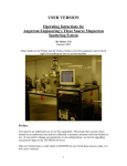
Gatan 682 Precision Etching and Coating System (PECS) Simplified coating instructions The PECS has the ability to sputter coat material on to a surface. This brief guide will cover using argon ions to sputter coat a thin film on to a sample. Information about etching and more detailed sputtering information can be found in the user manual. 0. Start the use log on the PC. SETUP AND PURGING THE GUNS: Before the PECS can be used, it must be properly setup. 1. Open the valve on the wall (Located in the left back corner) to start the argon flow (see Figure 1). One of the tools has a small leak and the tank will be depleted quickly if not closed after each use. Figure 1. Argon valve in closed position 2. The default configuration of the tool is… A) To have both targets extracted (copper rods visible) Right Target Left Target Figure 2a. Left and right target both in default “extracted” position B) The sample holder is in the “IN” position, and the rotation cable disconnected Sample Holder Rotation Cable Figure 2b. Sample holder is “IN” Rotational Cable is disconnected C) The LCD display will show the fore line pressure of less than 3 Torr and the molecular diffusion pump MDR should read 100%. Figure 2c. Foreline is less than 3 Torr, MDP RPM is 100% D) The analog gauge on the right will be around 10 -6 Torr. Confirm that this is how the tool is set. Figure 2d. Cathode Gauge in default position 3. Purge the guns. There are two toggle switches that say “left gun” and “right gun” (see Figure 3a). that when enabled have an indicator light. Note that either the sputtering guns can be enabled or the etch gun, but not both. Purge for 10 minutes. Figure 3a. Turn on “left gun” and “right gun” toggle switches Figure 3b. Set timer for 10 minutes and push start to purge the guns Lights show guns are enabled Figure 3c. Lights will indicate if guns are enabled OPTIMIZING THE GUNS ION CURRENT: VERIFY WITH STAFF (GENERALLY THIS STEP CAN BE SKIPPED IF THE ION CURRENT HAS BEEN OPTIMIZED RECENTLY) 4. Adjust the timer to 5 minutes (5:00) and adjust the beam energy (8kv is a good starting value). Holding the “stop” button for about 5 seconds resets the timer. Figure 4a. Beam Energy Enable gas flow with the toggle switches. Pressing the start button engages the high voltage and starts the timer counting down. The guns will heat slightly over about 4 minutes, allow the ion currents to stabilize before continuing. Enable gas flow with the toggle switches Adjust the flow for each gun individually Figure 4b. Observe the ion current for each gun individually Figure 4c. Slightly adjust the flow rate (1/8 turn) and observe the ion current. Each gun is adjusted independently, although the total pressure will affect both guns. When the gun is working, the light on the outside of the gun will illuminate. The current is more stable in this region Figure 4d. As the flow is adjusted the ion current will peak quickly and start to fall. The current will rise with rising pressure, saturate, and then fall slightly. The current is more stable in the pressure region greater than the maximum value. Maximum ion current happens at pressures less than 2x10 -5 torr. Turn off the high voltage by pressing the stop button. INSERTING AND SPUTTERING THE SAMPLE: After the PECS has been setup and purged 5. On the left side of the chamber is a large knob (50 mm diameter) and also a black toggle switch on the top of the chamber. The large knob is a shield that can cover the sample and is also a current meter for the etch gun. Shielding the sample allows adjustment of the sputter guns without contaminating the sample. The toggle switch opens a pneumatically driven shutter for the view port and also turns on a sample illumination light. The toggle switch on the top right opens and closes the shutter only. THE SHIELD MUST BE OPEN WHEN SPUTTERING YOUR SAMPLE Figure 5. Shield knob 6. On the front panel in the air lock control section, move the air lock toggle to the “out” position. This is driven pneumatically by the argon and takes about 5 seconds. Figure 6. Close-up of Airlock Control 7. Briefly press the “vent” button. The venting pressure may be enough to make the holder jump out of the guide, be prepared to catch it. Figure 7a. Holder in normal “IN” position Figure 7b. Holder in “Out” Position 8. Remove the holder and place in the cradle. The holder has 4 holes which a SEM stub can be placed. The center hole works better for a single sample on a 12.5mm diameter stub (1⁄2 inch) and the outer holes can fit several 12.5mm stubs at the same time. Figure 8. Holder in the Cradle 9. Insert the holder completely into the guide and then press and hold “vac” button. The fore line pressure gauge will briefly spike and then return to normal in about 10 seconds. Once the fore line pressure has returned to less than 3 Torr, move the toggle switch in the airlock control to “IN” and guide the holder to the inward position noting that the guide pin needs to be seated properly. Press “vac” button and wait for Foreline pressure to return to < 3 Torr Figure 9a. Close-up of Airlock Control Figure 9b. Align the guide pin so it seats properly 10. Insert target and move the thickness monitor into place. There are two targets mounted on each stick. Insert copper rod and then rotate knob to select desired target, there is a text label on the knob. The targets on the left rod are Au/Pd, and the second target is platinum. The right rod has carbon and chromium. Note if using Cr alert the lab staff to aide in additional setup. Figure 10a. The Au/Pd Target is inserted Thickness monitor is attached via BNC cable Figure 10b. Thickness monitor is connected and set to “Sensor” 11. Prepare the thickness monitor. Rotate the thickness sensor/ shield knob to sensor. Attach BNC cable to external thickness monitor and turn it on. The display will show “fail”, this is normal. Press stop button to clear. Select film parameters on thickness monitor. Film 1 has been set to Au/Pd, impedance 23.50 density 14.81 ;film 2 Pt impedance 36.04 density 21.40; film 3 Carbon with impedance 40.14, density 3.52; and film 4 Cr Impedance 28.95, 7.20. Tooling factor of 180 for all four films. Select “Film Parameters” to specify which target is being used Press stop to clear Figure 11. Thickness Monitor after turning it on 12. Configure rock and rotate. Rotate spins the sample in the plane of the holder, rock moves it perpendicular to that plane. Rock is useful for rough samples to enable coating the sides. These can both be used to create a more even coating. A rotation rate 20 RPM is a good start and the toggle should be on. Viewing the sample through the view port can see how these are used. Figure 12. Rock/Rotate control 13. Start sputtering. Set timer for total deposition time, enable gas flow, enable high voltage by pressing start. The thickness monitor should indicate approximate thickness and should get larger with time. For a current of 200 uA from each gun, typical sputtering rates for Au/Pd is 1.1 A/s, C is 0.1 A/s, Pt is 0.7 A/s. SHUTDOWN AND SAMPLE REMOVAL: 14. When desired thickness is reached, Turn off high voltage by pushing stop on the timer. Turn off gas flow toggle switches. Stop rotation if enabled. Extract target, rotate knob with target and copper rod then pull. 15. Remove sample. Take off rotation cable Set airlock control position toggle to “out” Press“vent” Remove sample Insert holder into tube Press “vac” When fore line pressure is stable move toggle to “in”. 16. Turn off argon valve at wall. 17. Stop the log PC timer.