1
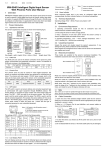
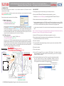
TL2730S
soloFace Standalone Access Controller for 2,730 ID cards
Dimensions: 97mm x 57mm x 23.5mm
1. INTRODUCTION
The TL2730S proximity access controller
control and time recording
is a cost effective solution for 2,728 users for access
2. QUICK START
Present an authorized card to the TL2730S, the red LED and relay will turn on as set by TMR0,
TMR1 and TMR2 with a beep sound. On the other hand, if an unauthorized card is presented to
the TL2730S, the red LED and the relay will have no action but with a long beep sound.
In this mode, only a single controller is installed outside the premises. An Electric strike can
be connected. A bypass switch is installed inside the premises, pressing it will release the
strike. While connecting the TL2730S’s RS232 port to the computer and running the Time
Logger software (Windows), the program will stamp the clocked date, time and card ID into
the computer database and show up the associated picture with the specific ID on the
computer screen for attendance reports. (See section 5 for wiring)
Goto 2.6 if use the Time Logger for granting authorization, keeping card information and reporting
(See section 3.5 and 4.2 in Time Logger’s User Manual for details).
2.5 Record the authorized ID card number and the associated personnel. This is for removing
the authorized card number in case of card losing.
In this mode, one TL2730S is installed outside the premises for entrance. Another TL2730S is
installed inside the premises for exit. An electric strike and a bypass switch are connected to
the OUT reader (for exit) inside the premises. Pressing the bypass switch or presenting the
authorized cards will release the strike. Clocked data will be sent from both the IN and OUT
reader to Time Logger’s database if connection is good.
Master Reader Set up
*** Setup the jumper blocks according to section 3
*** Setup the MASTER & ACTION card from the master reader
*** Use the ACTION CARD to authorize the ID cards
Mode of operation in Setup/ Reader
in Time Logger = OUT
An input contacts is provided, if it is shorted, the unit will respond the same as an authorized card
read.
2.4 Use the ACTION card to authorize the ID cards (see appendix A - section 3).
B. OUT Mode -Dual reader
use a TL2730S for Entrance + another TL2730S for Exit
+ PC based TIME LOGGER (with PC ON)
Bypass
switch
2.2 Set up your MASTER and ACTION card according to appendix A - section 1.
2.3 Remove all authorized key card (see appendix A - section 4).
A. IN Mode - Single reader
use TL2730S for entrance +
PC based TIME LOGGER (with PC ON)
For audit trail and attendance reports
Outside for Entrance
Slave Reader (TL2730S) Set up
*** Jumper setup for slave
2.6 Power off the reader
2.7 Connect the RS232 cable (straight through) from the computer to the terminal block of RS232
port. (See Terminal Layout)
2.8 Power on the reader
2.9 Turn on the computer.
2.10 Insert the Time Logger CD into your computer's CD-ROM drive. The Installer will start by
itself automatically. If the Installer doesn't start automatically, you can run the setup.exe
program to install the software.
2.11 The detailed installation manual for the Time Logger will be automatically installed
into your computer when you install the application software. Follow the
installation instruction to finish the installation and follow the Installation Manual of
Time Logger from Start for details of Time Logger’s Setup.
m
A)
NORMAL OPEN
COMMON
NORMAL CLOSE
PIN1
PIN2
PIN3
PIN4
PIN5
PIN6
PIN7
PIN8
Installation Manual of
Time Logger from Start
PIN1
PIN2
PIN3
PIN4
PIN5
PIN6
PIN7
PIN8
( TO
PO
WE
R-
9-
12
V6
00
Power
Electric
strike
www.avea.cc
Remember to remove the CLRM jumper after setting up the MASTER and ACTION card.
There are three modes of operation, in Setup / Reader :
Inside for Exit
RELAY TERM IN A L
( T O ELE C TRIC S T R IK E )
soloFace
2.1 Configuring the jumper blocks according to your needs (see section 3).
A 9 to 12V DC supply is required to power the reader, which has a current consumption of less than
300mA ( 600mA for dual reader ).
Wiring Illustration
RFID Access Controller with PC Based
Time Logger for audit trail & Attendance Reports
RS232 PORT
( TO COMPU T ER )
see section 5 for D B 9 w i ri ng
Wir i n g fr om MA STER t o S LAVE:
Master PIN3 t o Sl a ve PIN3
Master PIN6 t o Sl a ve PIN6
Master PIN7 t o Sl a ve PIN5
Master PIN8 t o Sl a ve PIN4
C. CLOCK Mode - Single reader, all logged records will be stamped as clock entries.
Time Logger
Time Logger
soloFace Standalone Access Controller for 2,730 ID cards
Dimensions: 97mm x 57mm x 23.5mm
Time Logger Quick Start
5. Insert the ID card CD
ROM to the computer to
ADD Cards and Edit Card
Information
6. Uploading the
authorization table to
the reader
1. Setup the password
for LOGIN first
9mm
12 mm
4. Define the workgroup
3. Setup the RFID reader
57 mm
Present the ID cards to
the reader, if the com
port set up correctly,
the record will be
shown on the screen
S LAV E
5. TERMINAL LAYOUT
( B YPAS S SWITC H) G N D
OPEN SW
N O R M AL O P E N
(R EL AY) C OM MON
NORMA L CLO SE
(PO WER SUPPLY, G N D
9 - 1 2 V 3 00 mA) D C IN
GND - D B9 PIN 5 t o PIN3
3. JUMPER SETTING
There is a 5-position jumper block for configuring the operation of the unit.
TMR2
OFF
OFF
OFF
OFF
ON
ON
ON
ON
TMR1
OFF
OFF
ON
ON
OFF
OFF
ON
ON
D ATA FROM P C - DB9 PIN 3 to PI N 4
D ATA TO PC - DB 9 PI N 2 t o PI N 5
FUNCTION
To select the relay on time with authorization granted.
R S2 3 2 P OR T
(TO C OMP UTE R )
ON: to reverse the operation of the relay.
ON: to clear the MASTER and ACTION card memory.
TMR0
OFF
ON
OFF
ON
OFF
ON
OFF
ON
FUNCTION
Relay on for 1 second on authorization granted.
Relay on for 2 seconds on authorization granted.
Relay on for 5 seconds on authorization granted.
Relay on for 10 seconds on authorization granted.
Relay on for 20 seconds on authorization granted.
Relay on for 50 seconds on authorization granted.
Relay on for 100 seconds on authorization granted.
Relay state is toggled on each authorization granted.
* ON : Jumper shorted, OFF : Jumper opened
*** Jumper setting for
slave reader
S LAV E
JUMPER POSITION
TMR2
TMR1
TMR0
RVSE
CLRM
soloFace
4. DIMENSIONS
97mm
2. Login the Time Logger
to start SETUP
RFID Access Controller with PC Based
Time Logger for audit trail & Attendance Reports
2 3 .5 m m
TL2730S
Power supply
negative terminal
Power supply
positive terminal
PIN1
PIN2
PIN3
PIN4
PIN5
PIN6
PIN7
PIN8
www.avea.cc