1
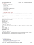
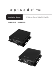
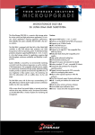
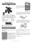
SC-88 Disk Box USER’S MANUAL Copyright © 2007 Sans Digital. Copyright and Trademarks The information of the products in this manual is subject to change without priornotice and does not represent a commitment on the part of the vendor, who assumes no liability or responsibility for any errors that may appear in this manual. Sans Digital is the trademarks of Sans Digital All brands and trademarks are the properties of their respective owners.This manual contains materials protected under International Copyright Conventions.All rights reserved. No part of this manual may be reproduced in any form or by any means, electronic or mechanical, including photocopying, without the written permission of the manufacturer and the author. All inquiries should be addressed to Sans Digital Table of Contents Chapter 1. Introduction...................................................... 1.1 Overview ....................................................................... 1.2 Features ......................................................................... 1.3 Specifications ................................................................ 1.4 System Outlook.............................................................. 1.5 HDD Compatibility......................................................... 1.6 Signal LEDs...................................................................... 1.7 About SCSI ..................................................................... Chapter 2. Installation ....................................................... 2.1 Installing SC88................................................................. Chapter 3. Mechanic Setting ............................................ 3.1 Setting DIP Switches ...................................................... 3.2 Adding SC88s ................................................................ 3.3 Replacing HDDs ............................................................ Chapter 4. Troubleshooting................................................ 1 1 1 2 2 3 3 4 5 5 12 12 13 14 15 S C 8 8 U S E R ’ S 1 Chapter M A N U A L 1.1 Overview SC88 can connect 4 IDE hard drives in Master/Slave mode at most. The Disk Box can also support a hard drive larger than 400GB through the 48-bit LBA (Logic Block Addressing) technology. And by SCSI daisy chain, up to 7 sets of SC88 can be connected to expand the whole system’s storage capacity 1.2 Features For enhancing the performance of hard drives and the stability of data transfer, the controller board of SC88 can be set in Spanning or JBOD Normal mode. Spanning means to let 2 or more hard drives become a big one while JBOD to maintain the capacity of each hard drive. The chip also has a SCSI ID,which owns 4 LUNs (Logical Unit No.). Accordingly, the number of hard drives appearing on the PC can be 1 (Spanning mode) or 4 (JBOD mode). _ High capacity of data storage reaches 4 IDE hard drives. _ BigDrives Technology supports 500GB and above drive capacity. _ Fully supports Ultra160 LVD SCSI features. _ On-board Flash ROM is easy for firmware update. 1 S C 8 8 U S E R ’ S M A N U A L 1.3 Specifications ¾ ¾ ¾ ¾ ¾ ¾ ¾ ¾ ¾ ¾ ¾ Host Interface Ultra160 LVD SCSI up to 160MB/sec transfer rate External SCSI port for daisy chain up to 7 boxes Selectable SCSI ID from 0 to 15 One SCSI ID to configure hard drives in Spanning or JBOD HDD Type Supports ATA 133/100/66/33 hard drive HDD Expansion Supports 500GB HDD with BigDrives Technology Maximum capacity of 14TB by connecting 7 units, 28 PCs 500GB hard drives Two independent channels of IDE bus,Four internal IDE connector. Management On-board Flash ROM for firmware update Spanning or JBOD mode selected by DIP switch Environment 0°C~50°C (32°F~122°F) for operation -20°C~70°C (-4°F~158°F) for storage Safety FCC, CE Power Power supply of 160W AC input voltage: 47~63Hz ,100~127V/3A; 200~240V/1.5A 1.4 System Outlook * Model: SC88TA does not have an LCD panel 2 S C 8 8 U S E R ’ S M A N U A L 1.5 HDD Compatibility SC88 supports any DMA 133/100/66/33 hard drives produced by the following world famous manufacturers. ¾ HITACHI ¾ Maxtor ¾ Seagate ¾ Western Digital 1.6 Signal LEDs There are 8 LEDs in 4 groups on the front panel of SC88 Each group of 2 LEDs shows the status of a hard drive. The red/green LED shows two different conditions. When it is green, the hard drive is normal, but when red, abnormal or not installed. Another yellow LED shows that the hard drive is busy. 3 S C 8 8 U S E R ’ S M A N U A L 1.7 About SCSI Please be aware of the following issues before using SCSI devices. (1). SCSI ID: Each device attached to the SCSI host adapter must be assigned a unique SCSI ID, which distinctively identifies a SCSI device for its data transfer and processing. While connecting more than one SCSI devices, it’s not necessary to use sequential SCSI ID numbers as long as the host adapter and each device have different numbers. For Ultra2 Wide SCSI interface, the selectable SCSI ID is from 0 to 15. But 7 is usually reserved for the SCSI adapter. (2). Terminator: SCSI is featured with high scalability. In order to ensure reliable ata transmission on the SCSI bus, a terminator should be installed at the end of the bus. No matter how many SCSI devices are attached to the bus, the last device must be installed with a terminator 4 S C 8 8 U S E R ’ S M A N U A L Chapter 2 2.1 Installing SC88 Be sure that all devices are not plugged in before completing the installation. 1. Open the front case and back case by removing the screws with a screwdriver as shown below. Figure 2.1 5 S C 8 8 U S E R ’ S M A N U A L 2. Pull the front case out and downward Figure 2.2 3. Pull the HDD Kit out the mount kit. 6 S C 8 8 U S E R ’ S M A N U A L Figure 2.3 4. Set the IDE hard drives as Master or Slave according to their location.Insert the HDD jumper to cable select and DC power cable and IDE cable on the HDD. Figure 2.4 5. Position the HDD into the tray and secure the HDD using the HDD screws provided. Figure 2.5 7 S C 8 8 U S E R ’ S M A N U A L 6. Put the HDD into the case and go on(4)~(5) Figure 2.6 7. Connect the IDE hard drives and the IDE ports on the controller board with an IDE cable. Connect the far end of the cableto the IDE ports, and the two near ends to the hard drives. Be aware of the direction of foolproof design. NOTICE If the hard drive have been set as Master or Slave, the two connectors can be inserted into either hard drive on the same channel. Yet , you need to connect according to primary or secondary IDE ports on Figure 2.7. Only thus can LED correspond to the place where the hard drives are and become lighted. 8 S C 8 8 U S E R ’ S M A N U A L Figure 2.7 9 S C 8 8 U S E R ’ S M A N U A L 8. Connect the cables of power and the 4 hard drives respectively. Set SCSI ID on the SCSI ID push-wheel switch. 9. Connect any one of the SCSI ports on the back of SC88 to the external SCSI port on the host with the given SCSI cable. If there is no vacant SCSI port on the host, please insert a SCSI adapter on the motherboard first. 10 S C 8 8 U S E R ’ S M A N U A L 10. Plug a terminator into another SCSI port on the back of SC88. Use SCSI Cable to connect two or more SC88, and install the terminator at the last SC88. 11. Close the lock of the front case and plug in the Disk Box, and examine if the LEDs on the front panel are the normal. 11 S C 8 8 U S E R ’ S M A N U A L Chapter 3 3.1 Setting DIP Switches This chapter is about the relevant mechanic setting of SC88. On the back of SC88 there is only one 4-pin DIP switch. By the switch the operating mode of all hard drives can be set. The defaults of all the 4 pins are OFF. OFF (Defaults are all OFF) ON Pin# Mode JBOD Normal 1 2 Transfer Rate 3 4 Pin1 Pin 2 Pin 3 Pin4 160MB/sec OFF OFF OFF ON 80MB/sec OFF OFF OFF OFF 40MB/sec OFF OFF ON OFF 160MB/sec OFF ON OFF ON 80MB/sec OFF ON OFF OFF 40MB/sec OFF ON ON OFF (1). Pin 2: Spanning Mode vs. JBOD Mode The default is Spanning Mode. It combines 2 or more hard drives into a big one. The enlarged capacity is convenient for data storage. (2). Pin 3: SCSI Host Transfer Rate at 80MB/sec vs. 40MB/sec The default is 80MB/sec. But if the SCSI adapter is not so capable, or the signals become unstable after connecting several SC88s, you are recommended to lower the speed to 40MB/sec. (3). Pin 4: SCSI Host Transfer Rate at 160MB/sec 12 S C 8 8 U S E R ’ S M A N U A L The default is OFF. But if pin 4 is adjusted to ON, the highest transfer rate will reach 160MB/sec. 3.2 Adding SC88s Please notice the following issues when you install two or more SC88s. (1). Power off the whole system: Please power off the host and all operating SC88s first. It is better to remove the power cords in order not to turn on the system by touching the button mistakenly during installation. (2). Connecting & Terminating: Repeat the procedures described in Chapter 2, and use cables to connect SC88s . The terminator can be reserved on the original SC88 or plugged to another one. (3). Setting SCSI ID & configuration mode: Be sure that each device has a unique ID number. No matter how many SC88s are installed and connected, the SCSI ID set on every push-wheel switch cannot be repeated. The selectable number for SC88 is from 0 to 15. But don’t select 7, that is preset for the host adapter. (4). After installation and setting, please power on the whole system and inspect the LED signals. 13 S C 8 8 U S E R ’ S M A N U A L Figure 3.3 Replacing HDDs Please take the following steps to replace the hard drives if it is necessary. (1). Power off the whole system, including the host and the installed SC88s, and remove the power cords. (2). Open the hand screw of the front case, pull the HDD kit out the tray. (3). Remove the power cable and IDE cable on the HDD. (4). Remove the screws on the back of the HDD kit to take the hard drive. (5). Replace with new hard drives and recover the machine system. 14 S C 8 8 U S E R ’ S M A N U A L Chapter 4 Troubleshooting If the installed SC88 does not function normally, please check the following items. Items Descrpition Please check if the power cord, (1). LEDs do not light under normal IDE cable and signal line are loose. circumstances If you have installed a hard drive, but the red LED lights, please do the following three things. 1. Re-plug the IDE cables and the status signal lines, which are 3-pin (2). Red LED lights after HDD is color installed cables connecting to CN6 (see Figure 3.1). 2. Replace the hard drive if the red LED still lights. 3. Contact the Technical Support if the problem still exists. That means there is a bad sector in the HDD. Please get a good HDD. (3). Green LED turns into red per 10 seconds after HDD is installed Check the BIOS screen while booting up the system. See if it displays LUN=3. (4). System does not show all HDDs in normal mode 15 S C 8 8 U S E R ’ S M A N U A L (5). HDD is not recognized in the If you cannot see the hard drives system installed on SC88 in OS, please take the following steps. Take Windows 2000 for example. 1. Right click “My Computer” and enter “Manage”. 2. Choose “Disk Management” under “Storage”, and a given hard drive ID will appear on the right lower corner of the window. 3. If the newly installed hard drive has no ID, please do “New Partition” and then “Format” it. 4. If the newly installed hard drive doesn’t appear on the screen, it may be improperly installed or damaged. Please try again. 16